EP1764586A2 - Dispositif d'interruption du contrôle de circulation des chauffe-eau muraux à allumage au gaz - Google Patents
Dispositif d'interruption du contrôle de circulation des chauffe-eau muraux à allumage au gaz Download PDFInfo
- Publication number
- EP1764586A2 EP1764586A2 EP06012503A EP06012503A EP1764586A2 EP 1764586 A2 EP1764586 A2 EP 1764586A2 EP 06012503 A EP06012503 A EP 06012503A EP 06012503 A EP06012503 A EP 06012503A EP 1764586 A2 EP1764586 A2 EP 1764586A2
- Authority
- EP
- European Patent Office
- Prior art keywords
- flow
- float
- control device
- casing
- fluid
- Prior art date
- Legal status (The legal status is an assumption and is not a legal conclusion. Google has not performed a legal analysis and makes no representation as to the accuracy of the status listed.)
- Granted
Links
Images
Classifications
-
- G—PHYSICS
- G01—MEASURING; TESTING
- G01F—MEASURING VOLUME, VOLUME FLOW, MASS FLOW OR LIQUID LEVEL; METERING BY VOLUME
- G01F1/00—Measuring the volume flow or mass flow of fluid or fluent solid material wherein the fluid passes through a meter in a continuous flow
- G01F1/05—Measuring the volume flow or mass flow of fluid or fluent solid material wherein the fluid passes through a meter in a continuous flow by using mechanical effects
- G01F1/20—Measuring the volume flow or mass flow of fluid or fluent solid material wherein the fluid passes through a meter in a continuous flow by using mechanical effects by detection of dynamic effects of the flow
- G01F1/22—Measuring the volume flow or mass flow of fluid or fluent solid material wherein the fluid passes through a meter in a continuous flow by using mechanical effects by detection of dynamic effects of the flow by variable-area meters, e.g. rotameters
- G01F1/24—Measuring the volume flow or mass flow of fluid or fluent solid material wherein the fluid passes through a meter in a continuous flow by using mechanical effects by detection of dynamic effects of the flow by variable-area meters, e.g. rotameters with magnetic or electric coupling to the indicating device
-
- H—ELECTRICITY
- H01—ELECTRIC ELEMENTS
- H01H—ELECTRIC SWITCHES; RELAYS; SELECTORS; EMERGENCY PROTECTIVE DEVICES
- H01H36/00—Switches actuated by change of magnetic field or of electric field, e.g. by change of relative position of magnet and switch, by shielding
- H01H36/02—Switches actuated by change of magnetic field or of electric field, e.g. by change of relative position of magnet and switch, by shielding actuated by movement of a float carrying a magnet
Definitions
- This invention refers to a magnetically actuated flow-control switch device of vertical float-type, for operating wall-mounted gas-fired boilers, according to the preamble of claim 1.
- the invention relates to a flow-control device of the aforementioned type, for controlling the ignition of gas-fired boilers for domestic use, designed to indifferently supply both hot water for a heating system and hot water for domestic use.
- a magnetically actuated flow-control switch device of float-type comprises a tubular body of plastic material or other suitable non magnetically conductive material, defining a longitudinal duct between an inlet pipe fitting and an outlet pipe fitting for the fluid, within which a flow sensing spool comprising a float and a permanent magnet slides; the float is entrained by the flowing fluid to operate a reed-type magnetic switch, providing control signals to control for example the ignition of a gas burner as soon as a light flow of water, caused for example by turning on a tap, or necessary for starting up a circulation pump of the fluid in a heating system, is flowing along the same flow-control device.
- a flow -control device of the aforesaid type is described for example in GB-A-2.243.953 .
- the flow control device comprises a tubular body, of plastic material, provided with fastening flanges at the fluid inlet and outlet sides, and an internal float appropriately shaped to define a peripheral path for the fluid; the float comprises a permanent magnet for operating a reed switch embedded into the tubular body at the moulding time.
- US-A-6.339.959 and US-A-6.898.984 in turn illustrate flow-control devices comprising a tubular body within which a hollow magnetic float slides; the float is provided with a permanent magnet having an axial hole for the passage of the fluid and comprises a cylindrical outer surface which extends along the entire length, or between annular flanges at the two ends.
- the limited length of the magnet necessary to avoid making the float excessively heavy, without jeopardising its sensitivity, has a negative effect on the operative range of the magnet for actuation of the reed switch.
- the simple cylindrical or flanged shape of the float it is not possible to sufficiently reduce and/or modify the operative threshold of the flow control device, without endangering its operative reliability.
- the main object of the invention is to provide a float-type flow-control device of the aforementioned type, which is structurally simple and of limited dimensions, while nevertheless maintaining a high degree of sensitivity and operative reliability in controlling a gas-fired boiler.
- a further object of the invention is to provide a float-type flow-control device, whereby it is possible, at the designing, to adapt and/or modify its operative threshold while maintaining the general features and the overall dimensions of the device unchanged.
- a still further object is to provide a float-type flow control device having a high degree of magnetic sensitivity, within a wide operative range of a reed switch, and to replace and/or change the position of the aforesaid reed switch also with the device already assembled in a working line.
- a float-type flow-control switch device comprising: a hollow casing of plastic material, defining a longitudinal duct having an inner surface axially extending between an inlet and an outlet for a fluid; a magnetic float sliding within said duct under the entraining action of the fluid, to generate a magnetic field for operation of a reed switch, characterised in that the float has an elongated body having a longitudinal flow hole for the fluid, axially extending between its fore and rear ends; and
- said body of the float comprises a fore cylindrical portion, and a rear conical portion defining, together with the inner surface of the longitudinal duct, an annularly shaped thrust chamber movable with the float.
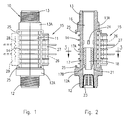
- the flow-control switch device As it can be seen from figures 1, 2 and 3, the flow-control switch device, indicated as a whole by reference 10, comprises a hollow casing 11 of plastic material, moulded in one piece with an inlet threaded pipe fitting 12 and an outlet threaded pipe fitting 13, for the inlet and outlet of a fluid, as shown.
- the casing 11 of the flow-control device is obtained in a single moulding together with the two threaded pipe fittings 12 and 13, by means of plastic material capable of withstanding thermal and mechanical stresses, and hydrolysis, in particular using plastic material suitable for liquid foodstuffs.
- the casing 11 of the flow-control device has a polygonal cross sectional shape, for example hexagonal, provided with a plurality of cross stiffening ribs 14, to make the casing 11 of the device highly resistant to the stresses caused by the water hammering that may occur in a hydraulic circuit when the fluid is suddenly shut off; the polygonal shape of the casing 11 and the stiffening ribs 14, also provide the possibility of removably positioning a reed switch 15 outwardly the same casing, as explained further on.
- the casing 11 of the flow-control switch device comprises a longitudinal duct 16 having an inner cylindrical surface which extends from the inlet threaded pipe fitting 12 to the outlet pipe fitting 13 for the inlet and outlet of the fluid.
- a movable magnetic element 17 for operating the reed switch 15 is slidably arranged inside the duct 16 to be vertically moved by the fluid thrust and its own weight in the duct 16.
- the movable magnetic element 17, also referred to as "float”, is designed to be entrained by the stream of the fluid which flows through the duct 16; it has an elongated body comprising a fore cylindrical portion 17A, and a rear portion 17B having substantially a conical shape, with the taper facing towards the inlet threaded pipe fitting 12.
- the float 17 has an elongated body provided with an axial hole 18 for the passage of the fluid, and external guiding and centering ribs 19 which extend in a longitudinal direction to the cylindrical portion 17A of the float body; in this way, between the outer surface of the float 17 and the inner surface of the longitudinal duct 16 a narrow annular hollow space 20 is created, which allows the passage of a film of fluid, which together with the guiding ribs 19 makes it possible to reduce the internal friction forces, thereby increasing the sensitivity of the flow-control device.
- the float 17 is obtained by moulding from magnetic plastic material, for example a polymeric material comprising a ferrite filler, or a filler of suitable magnetic material in powder form.
- the magnetic float 17 is permanently magnetised axially along its entire length; in this way it is possible to obtain a magnetic float of reduced dimensions, which is extremely light in weight and therefore highly sensitive to the flow of the fluid, having at the same time a magnetic field strong enough to operate the reed switch 15.
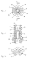
- the body of the float 17 at its rear end is provided with a conical portion 17B which, together with the inner cylindrical surface of the longitudinal duct 16, defines an annular chamber 21 movable with the float itself under the entraining action of the fluid, as shown in the detail of figure 4.
- the diameter of the inner hole of the float 17 can range from 4 to 8 mm, while the angle of the conical part, can range from 10° to 45°.
- figure 5 shows the possibility of making longitudinal slots 22 on the outer surface of the float body 17 to improve the circulation of the fluid film along the annular space 20, and change the operative thresholds of the flow-control device.
- Reference number 23 in figure 2 has been used to indicate a cup-shaped filter in correspondence with the inlet pipe fitting 12; the filter 23 is made in one piece by moulding from plastic material which, in addition to retaining any impurities that may be present in the fluid, constitutes a bottom stop member for the float 17; otherwise, the upper stop member consists of several ribs or protrusions 24 inside the duct 16, as shown in figures 2 and 4.
- the reed switch 15 is removably fitted and/or differently positionable outside the casing 11 of the flow-control device.
- the reed switch 15 comprises a bulb 26 containing the electric contacts that can be magnetically operated by the float 17; the bulb 26 is housed in a plastic container 27, which can be arranged by simply sliding it within the tabs 25;
Landscapes
- Physics & Mathematics (AREA)
- Fluid Mechanics (AREA)
- General Physics & Mathematics (AREA)
- Feeding And Controlling Fuel (AREA)
- Measuring Volume Flow (AREA)
- Switches Operated By Changes In Physical Conditions (AREA)
- Details Of Valves (AREA)
- Temperature-Responsive Valves (AREA)
Applications Claiming Priority (1)
| Application Number | Priority Date | Filing Date | Title |
|---|---|---|---|
| IT001701A ITMI20051701A1 (it) | 2005-09-15 | 2005-09-15 | Flussostato per caldaie a gas di tipo murali |
Publications (3)
| Publication Number | Publication Date |
|---|---|
| EP1764586A2 true EP1764586A2 (fr) | 2007-03-21 |
| EP1764586A3 EP1764586A3 (fr) | 2007-04-11 |
| EP1764586B1 EP1764586B1 (fr) | 2008-04-23 |
Family
ID=37113771
Family Applications (1)
| Application Number | Title | Priority Date | Filing Date |
|---|---|---|---|
| EP06012503A Not-in-force EP1764586B1 (fr) | 2005-09-15 | 2006-06-19 | Dispositif d'interruption du contrôle de circulation des chauffe-eau muraux à allumage au gaz |
Country Status (4)
| Country | Link |
|---|---|
| EP (1) | EP1764586B1 (fr) |
| AT (1) | ATE393378T1 (fr) |
| DE (1) | DE602006000987T2 (fr) |
| IT (1) | ITMI20051701A1 (fr) |
Cited By (4)
| Publication number | Priority date | Publication date | Assignee | Title |
|---|---|---|---|---|
| WO2011100959A1 (fr) * | 2010-02-17 | 2011-08-25 | Meister Strömungstechnik GmbH | Dispositif de surveillance d'un débit volumique et procédé de surveillance d'un débit volumique |
| DE102017111366A1 (de) | 2017-05-24 | 2018-11-29 | Endress+Hauser Conducta Gmbh+Co. Kg | Schwebekörper-Durchflussmessgerät |
| CN111029210A (zh) * | 2019-12-10 | 2020-04-17 | 安庆中船柴油机有限公司 | 一种多功能船用燃油液位开关 |
| CN111397673A (zh) * | 2020-04-15 | 2020-07-10 | 江苏鑫亚达仪表制造有限公司 | 一种反应灵敏的新型流量计 |
Families Citing this family (1)
| Publication number | Priority date | Publication date | Assignee | Title |
|---|---|---|---|---|
| CN107871641B (zh) * | 2016-09-22 | 2020-06-19 | 东莞市东坑合利美电子电器有限公司 | 排水装置的微动结构的组成 |
Citations (2)
| Publication number | Priority date | Publication date | Assignee | Title |
|---|---|---|---|---|
| US6339959B1 (en) * | 2000-05-10 | 2002-01-22 | N.M.F. Ltd. | Magnetic float type flowmeter |
| US6898984B2 (en) * | 2002-08-16 | 2005-05-31 | Levitronix Llc | Measuring apparatus to determine the flow of a fluid |
-
2005
- 2005-09-15 IT IT001701A patent/ITMI20051701A1/it unknown
-
2006
- 2006-06-19 DE DE602006000987T patent/DE602006000987T2/de active Active
- 2006-06-19 AT AT06012503T patent/ATE393378T1/de not_active IP Right Cessation
- 2006-06-19 EP EP06012503A patent/EP1764586B1/fr not_active Not-in-force
Patent Citations (2)
| Publication number | Priority date | Publication date | Assignee | Title |
|---|---|---|---|---|
| US6339959B1 (en) * | 2000-05-10 | 2002-01-22 | N.M.F. Ltd. | Magnetic float type flowmeter |
| US6898984B2 (en) * | 2002-08-16 | 2005-05-31 | Levitronix Llc | Measuring apparatus to determine the flow of a fluid |
Cited By (4)
| Publication number | Priority date | Publication date | Assignee | Title |
|---|---|---|---|---|
| WO2011100959A1 (fr) * | 2010-02-17 | 2011-08-25 | Meister Strömungstechnik GmbH | Dispositif de surveillance d'un débit volumique et procédé de surveillance d'un débit volumique |
| DE102017111366A1 (de) | 2017-05-24 | 2018-11-29 | Endress+Hauser Conducta Gmbh+Co. Kg | Schwebekörper-Durchflussmessgerät |
| CN111029210A (zh) * | 2019-12-10 | 2020-04-17 | 安庆中船柴油机有限公司 | 一种多功能船用燃油液位开关 |
| CN111397673A (zh) * | 2020-04-15 | 2020-07-10 | 江苏鑫亚达仪表制造有限公司 | 一种反应灵敏的新型流量计 |
Also Published As
| Publication number | Publication date |
|---|---|
| DE602006000987D1 (de) | 2008-06-05 |
| EP1764586B1 (fr) | 2008-04-23 |
| DE602006000987T2 (de) | 2009-05-28 |
| EP1764586A3 (fr) | 2007-04-11 |
| ITMI20051701A1 (it) | 2007-03-16 |
| ATE393378T1 (de) | 2008-05-15 |
Similar Documents
| Publication | Publication Date | Title |
|---|---|---|
| EP1764586B1 (fr) | Dispositif d'interruption du contrôle de circulation des chauffe-eau muraux à allumage au gaz | |
| US9593782B2 (en) | Fluid regulator with field convertible slam-shut device | |
| SE468721B (sv) | Ventilanordning foer att generera kortvariga tryckluftpulser exempelvis foer renblaasning av paasformiga filterelement | |
| EP2902682A1 (fr) | Soupape pilotée à piston flottant | |
| US20070095402A1 (en) | Pressure reducer | |
| US10533307B2 (en) | Fluid governing system | |
| CN100462565C (zh) | 自动泵 | |
| EP3973192A1 (fr) | Dispositif de commande de pompe | |
| JP7108518B2 (ja) | 負圧湿式予作動スプリンクラー設備における流量制御弁 | |
| GB2594320A (en) | Small water heater | |
| US5516077A (en) | Relief valve with integral drain line coupling | |
| JP2010031920A (ja) | 弁類の作動状態検出装置 | |
| WO2011001163A2 (fr) | Dispositif sphérique de vidange de radiateur | |
| JP6194403B2 (ja) | 電動弁 | |
| KR950008580Y1 (ko) | 가스보일러용 유수감지 장치 | |
| EP3693671B1 (fr) | Système de remplissage doté d'un dispositif d'actionnement thermique | |
| EP1460393B1 (fr) | Débitmètre avec capteur magnétique | |
| US20230417337A1 (en) | Deaerator with integrated shut-off valve | |
| GB2407859A (en) | Condensing boiler assembly with pressure sensor | |
| CN107806724B (zh) | 水系统保护装置、控制方法、水系统及空调器 | |
| KR100681339B1 (ko) | 연탄보일러 | |
| KR20170088801A (ko) | 자화기능을 갖는 체크밸브 | |
| JPH0740796Y2 (ja) | バルブ付スチームトラップ | |
| RU2065670C1 (ru) | Электроводонагреватель | |
| KR20110130280A (ko) | 플로우 스위치 |
Legal Events
| Date | Code | Title | Description |
|---|---|---|---|
| PUAI | Public reference made under article 153(3) epc to a published international application that has entered the european phase |
Free format text: ORIGINAL CODE: 0009012 |
|
| PUAL | Search report despatched |
Free format text: ORIGINAL CODE: 0009013 |
|
| AK | Designated contracting states |
Kind code of ref document: A2 Designated state(s): AT BE BG CH CY CZ DE DK EE ES FI FR GB GR HU IE IS IT LI LT LU LV MC NL PL PT RO SE SI SK TR |
|
| AX | Request for extension of the european patent |
Extension state: AL BA HR MK YU |
|
| AK | Designated contracting states |
Kind code of ref document: A3 Designated state(s): AT BE BG CH CY CZ DE DK EE ES FI FR GB GR HU IE IS IT LI LT LU LV MC NL PL PT RO SE SI SK TR |
|
| AX | Request for extension of the european patent |
Extension state: AL BA HR MK YU |
|
| 17P | Request for examination filed |
Effective date: 20070924 |
|
| 17Q | First examination report despatched |
Effective date: 20071024 |
|
| GRAP | Despatch of communication of intention to grant a patent |
Free format text: ORIGINAL CODE: EPIDOSNIGR1 |
|
| AKX | Designation fees paid |
Designated state(s): AT BE BG CH CY CZ DE DK EE ES FI FR GB GR HU IE IS IT LI LT LU LV MC NL PL PT RO SE SI SK TR |
|
| GRAS | Grant fee paid |
Free format text: ORIGINAL CODE: EPIDOSNIGR3 |
|
| GRAA | (expected) grant |
Free format text: ORIGINAL CODE: 0009210 |
|
| AK | Designated contracting states |
Kind code of ref document: B1 Designated state(s): AT BE BG CH CY CZ DE DK EE ES FI FR GB GR HU IE IS IT LI LT LU LV MC NL PL PT RO SE SI SK TR |
|
| REG | Reference to a national code |
Ref country code: GB Ref legal event code: FG4D |
|
| REG | Reference to a national code |
Ref country code: CH Ref legal event code: EP |
|
| REF | Corresponds to: |
Ref document number: 602006000987 Country of ref document: DE Date of ref document: 20080605 Kind code of ref document: P |
|
| REG | Reference to a national code |
Ref country code: IE Ref legal event code: FG4D Free format text: LANGUAGE OF EP DOCUMENT: FRENCH |
|
| PG25 | Lapsed in a contracting state [announced via postgrant information from national office to epo] |
Ref country code: SI Free format text: LAPSE BECAUSE OF FAILURE TO SUBMIT A TRANSLATION OF THE DESCRIPTION OR TO PAY THE FEE WITHIN THE PRESCRIBED TIME-LIMIT Effective date: 20080423 |
|
| NLV1 | Nl: lapsed or annulled due to failure to fulfill the requirements of art. 29p and 29m of the patents act | ||
| PG25 | Lapsed in a contracting state [announced via postgrant information from national office to epo] |
Ref country code: FI Free format text: LAPSE BECAUSE OF FAILURE TO SUBMIT A TRANSLATION OF THE DESCRIPTION OR TO PAY THE FEE WITHIN THE PRESCRIBED TIME-LIMIT Effective date: 20080423 Ref country code: NL Free format text: LAPSE BECAUSE OF FAILURE TO SUBMIT A TRANSLATION OF THE DESCRIPTION OR TO PAY THE FEE WITHIN THE PRESCRIBED TIME-LIMIT Effective date: 20080423 Ref country code: PT Free format text: LAPSE BECAUSE OF FAILURE TO SUBMIT A TRANSLATION OF THE DESCRIPTION OR TO PAY THE FEE WITHIN THE PRESCRIBED TIME-LIMIT Effective date: 20080923 Ref country code: BG Free format text: LAPSE BECAUSE OF FAILURE TO SUBMIT A TRANSLATION OF THE DESCRIPTION OR TO PAY THE FEE WITHIN THE PRESCRIBED TIME-LIMIT Effective date: 20080723 Ref country code: ES Free format text: LAPSE BECAUSE OF FAILURE TO SUBMIT A TRANSLATION OF THE DESCRIPTION OR TO PAY THE FEE WITHIN THE PRESCRIBED TIME-LIMIT Effective date: 20080803 |
|
| PG25 | Lapsed in a contracting state [announced via postgrant information from national office to epo] |
Ref country code: LV Free format text: LAPSE BECAUSE OF FAILURE TO SUBMIT A TRANSLATION OF THE DESCRIPTION OR TO PAY THE FEE WITHIN THE PRESCRIBED TIME-LIMIT Effective date: 20080423 Ref country code: PL Free format text: LAPSE BECAUSE OF FAILURE TO SUBMIT A TRANSLATION OF THE DESCRIPTION OR TO PAY THE FEE WITHIN THE PRESCRIBED TIME-LIMIT Effective date: 20080423 Ref country code: AT Free format text: LAPSE BECAUSE OF FAILURE TO SUBMIT A TRANSLATION OF THE DESCRIPTION OR TO PAY THE FEE WITHIN THE PRESCRIBED TIME-LIMIT Effective date: 20080423 |
|
| PG25 | Lapsed in a contracting state [announced via postgrant information from national office to epo] |
Ref country code: IS Free format text: LAPSE BECAUSE OF FAILURE TO SUBMIT A TRANSLATION OF THE DESCRIPTION OR TO PAY THE FEE WITHIN THE PRESCRIBED TIME-LIMIT Effective date: 20080823 |
|
| PG25 | Lapsed in a contracting state [announced via postgrant information from national office to epo] |
Ref country code: CZ Free format text: LAPSE BECAUSE OF FAILURE TO SUBMIT A TRANSLATION OF THE DESCRIPTION OR TO PAY THE FEE WITHIN THE PRESCRIBED TIME-LIMIT Effective date: 20080423 Ref country code: MC Free format text: LAPSE BECAUSE OF NON-PAYMENT OF DUE FEES Effective date: 20080630 Ref country code: DK Free format text: LAPSE BECAUSE OF FAILURE TO SUBMIT A TRANSLATION OF THE DESCRIPTION OR TO PAY THE FEE WITHIN THE PRESCRIBED TIME-LIMIT Effective date: 20080423 Ref country code: SE Free format text: LAPSE BECAUSE OF FAILURE TO SUBMIT A TRANSLATION OF THE DESCRIPTION OR TO PAY THE FEE WITHIN THE PRESCRIBED TIME-LIMIT Effective date: 20080723 Ref country code: LT Free format text: LAPSE BECAUSE OF FAILURE TO SUBMIT A TRANSLATION OF THE DESCRIPTION OR TO PAY THE FEE WITHIN THE PRESCRIBED TIME-LIMIT Effective date: 20080423 |
|
| EN | Fr: translation not filed | ||
| PG25 | Lapsed in a contracting state [announced via postgrant information from national office to epo] |
Ref country code: SK Free format text: LAPSE BECAUSE OF FAILURE TO SUBMIT A TRANSLATION OF THE DESCRIPTION OR TO PAY THE FEE WITHIN THE PRESCRIBED TIME-LIMIT Effective date: 20080423 Ref country code: RO Free format text: LAPSE BECAUSE OF FAILURE TO SUBMIT A TRANSLATION OF THE DESCRIPTION OR TO PAY THE FEE WITHIN THE PRESCRIBED TIME-LIMIT Effective date: 20080423 Ref country code: BE Free format text: LAPSE BECAUSE OF FAILURE TO SUBMIT A TRANSLATION OF THE DESCRIPTION OR TO PAY THE FEE WITHIN THE PRESCRIBED TIME-LIMIT Effective date: 20080423 |
|
| PLBE | No opposition filed within time limit |
Free format text: ORIGINAL CODE: 0009261 |
|
| STAA | Information on the status of an ep patent application or granted ep patent |
Free format text: STATUS: NO OPPOSITION FILED WITHIN TIME LIMIT |
|
| 26N | No opposition filed |
Effective date: 20090126 |
|
| REG | Reference to a national code |
Ref country code: IE Ref legal event code: MM4A |
|
| PG25 | Lapsed in a contracting state [announced via postgrant information from national office to epo] |
Ref country code: IE Free format text: LAPSE BECAUSE OF NON-PAYMENT OF DUE FEES Effective date: 20080619 Ref country code: FR Free format text: LAPSE BECAUSE OF FAILURE TO SUBMIT A TRANSLATION OF THE DESCRIPTION OR TO PAY THE FEE WITHIN THE PRESCRIBED TIME-LIMIT Effective date: 20090227 Ref country code: EE Free format text: LAPSE BECAUSE OF FAILURE TO SUBMIT A TRANSLATION OF THE DESCRIPTION OR TO PAY THE FEE WITHIN THE PRESCRIBED TIME-LIMIT Effective date: 20080423 |
|
| PG25 | Lapsed in a contracting state [announced via postgrant information from national office to epo] |
Ref country code: LU Free format text: LAPSE BECAUSE OF NON-PAYMENT OF DUE FEES Effective date: 20080619 Ref country code: HU Free format text: LAPSE BECAUSE OF FAILURE TO SUBMIT A TRANSLATION OF THE DESCRIPTION OR TO PAY THE FEE WITHIN THE PRESCRIBED TIME-LIMIT Effective date: 20081024 Ref country code: CY Free format text: LAPSE BECAUSE OF FAILURE TO SUBMIT A TRANSLATION OF THE DESCRIPTION OR TO PAY THE FEE WITHIN THE PRESCRIBED TIME-LIMIT Effective date: 20080423 |
|
| PG25 | Lapsed in a contracting state [announced via postgrant information from national office to epo] |
Ref country code: TR Free format text: LAPSE BECAUSE OF FAILURE TO SUBMIT A TRANSLATION OF THE DESCRIPTION OR TO PAY THE FEE WITHIN THE PRESCRIBED TIME-LIMIT Effective date: 20080423 |
|
| PG25 | Lapsed in a contracting state [announced via postgrant information from national office to epo] |
Ref country code: GR Free format text: LAPSE BECAUSE OF FAILURE TO SUBMIT A TRANSLATION OF THE DESCRIPTION OR TO PAY THE FEE WITHIN THE PRESCRIBED TIME-LIMIT Effective date: 20080724 |
|
| REG | Reference to a national code |
Ref country code: CH Ref legal event code: PL |
|
| GBPC | Gb: european patent ceased through non-payment of renewal fee |
Effective date: 20100619 |
|
| PG25 | Lapsed in a contracting state [announced via postgrant information from national office to epo] |
Ref country code: CH Free format text: LAPSE BECAUSE OF NON-PAYMENT OF DUE FEES Effective date: 20080630 Ref country code: LI Free format text: LAPSE BECAUSE OF NON-PAYMENT OF DUE FEES Effective date: 20080630 |
|
| PG25 | Lapsed in a contracting state [announced via postgrant information from national office to epo] |
Ref country code: LI Free format text: LAPSE BECAUSE OF NON-PAYMENT OF DUE FEES Effective date: 20100630 Ref country code: CH Free format text: LAPSE BECAUSE OF NON-PAYMENT OF DUE FEES Effective date: 20100630 |
|
| PG25 | Lapsed in a contracting state [announced via postgrant information from national office to epo] |
Ref country code: GB Free format text: LAPSE BECAUSE OF NON-PAYMENT OF DUE FEES Effective date: 20100619 |
|
| PGFP | Annual fee paid to national office [announced via postgrant information from national office to epo] |
Ref country code: DE Payment date: 20120620 Year of fee payment: 7 |
|
| PGFP | Annual fee paid to national office [announced via postgrant information from national office to epo] |
Ref country code: IT Payment date: 20120629 Year of fee payment: 7 |
|
| REG | Reference to a national code |
Ref country code: DE Ref legal event code: R082 Ref document number: 602006000987 Country of ref document: DE Representative=s name: MAIWALD PATENTANWALTS GMBH, DE |
|
| REG | Reference to a national code |
Ref country code: DE Ref legal event code: R119 Ref document number: 602006000987 Country of ref document: DE Effective date: 20140101 |
|
| PG25 | Lapsed in a contracting state [announced via postgrant information from national office to epo] |
Ref country code: DE Free format text: LAPSE BECAUSE OF NON-PAYMENT OF DUE FEES Effective date: 20140101 |
|
| PG25 | Lapsed in a contracting state [announced via postgrant information from national office to epo] |
Ref country code: IT Free format text: LAPSE BECAUSE OF NON-PAYMENT OF DUE FEES Effective date: 20130619 |