EP1764586A2 - Flow-control switch device for gas-fired wall boilers - Google Patents
Flow-control switch device for gas-fired wall boilers Download PDFInfo
- Publication number
- EP1764586A2 EP1764586A2 EP06012503A EP06012503A EP1764586A2 EP 1764586 A2 EP1764586 A2 EP 1764586A2 EP 06012503 A EP06012503 A EP 06012503A EP 06012503 A EP06012503 A EP 06012503A EP 1764586 A2 EP1764586 A2 EP 1764586A2
- Authority
- EP
- European Patent Office
- Prior art keywords
- flow
- float
- control device
- casing
- fluid
- Prior art date
- Legal status (The legal status is an assumption and is not a legal conclusion. Google has not performed a legal analysis and makes no representation as to the accuracy of the status listed.)
- Granted
Links
Images
Classifications
-
- G—PHYSICS
- G01—MEASURING; TESTING
- G01F—MEASURING VOLUME, VOLUME FLOW, MASS FLOW OR LIQUID LEVEL; METERING BY VOLUME
- G01F1/00—Measuring the volume flow or mass flow of fluid or fluent solid material wherein the fluid passes through a meter in a continuous flow
- G01F1/05—Measuring the volume flow or mass flow of fluid or fluent solid material wherein the fluid passes through a meter in a continuous flow by using mechanical effects
- G01F1/20—Measuring the volume flow or mass flow of fluid or fluent solid material wherein the fluid passes through a meter in a continuous flow by using mechanical effects by detection of dynamic effects of the flow
- G01F1/22—Measuring the volume flow or mass flow of fluid or fluent solid material wherein the fluid passes through a meter in a continuous flow by using mechanical effects by detection of dynamic effects of the flow by variable-area meters, e.g. rotameters
- G01F1/24—Measuring the volume flow or mass flow of fluid or fluent solid material wherein the fluid passes through a meter in a continuous flow by using mechanical effects by detection of dynamic effects of the flow by variable-area meters, e.g. rotameters with magnetic or electric coupling to the indicating device
-
- H—ELECTRICITY
- H01—ELECTRIC ELEMENTS
- H01H—ELECTRIC SWITCHES; RELAYS; SELECTORS; EMERGENCY PROTECTIVE DEVICES
- H01H36/00—Switches actuated by change of magnetic field or of electric field, e.g. by change of relative position of magnet and switch, by shielding
- H01H36/02—Switches actuated by change of magnetic field or of electric field, e.g. by change of relative position of magnet and switch, by shielding actuated by movement of a float carrying a magnet
Definitions
- This invention refers to a magnetically actuated flow-control switch device of vertical float-type, for operating wall-mounted gas-fired boilers, according to the preamble of claim 1.
- the invention relates to a flow-control device of the aforementioned type, for controlling the ignition of gas-fired boilers for domestic use, designed to indifferently supply both hot water for a heating system and hot water for domestic use.
- a magnetically actuated flow-control switch device of float-type comprises a tubular body of plastic material or other suitable non magnetically conductive material, defining a longitudinal duct between an inlet pipe fitting and an outlet pipe fitting for the fluid, within which a flow sensing spool comprising a float and a permanent magnet slides; the float is entrained by the flowing fluid to operate a reed-type magnetic switch, providing control signals to control for example the ignition of a gas burner as soon as a light flow of water, caused for example by turning on a tap, or necessary for starting up a circulation pump of the fluid in a heating system, is flowing along the same flow-control device.
- a flow -control device of the aforesaid type is described for example in GB-A-2.243.953 .
- the flow control device comprises a tubular body, of plastic material, provided with fastening flanges at the fluid inlet and outlet sides, and an internal float appropriately shaped to define a peripheral path for the fluid; the float comprises a permanent magnet for operating a reed switch embedded into the tubular body at the moulding time.
- US-A-6.339.959 and US-A-6.898.984 in turn illustrate flow-control devices comprising a tubular body within which a hollow magnetic float slides; the float is provided with a permanent magnet having an axial hole for the passage of the fluid and comprises a cylindrical outer surface which extends along the entire length, or between annular flanges at the two ends.
- the limited length of the magnet necessary to avoid making the float excessively heavy, without jeopardising its sensitivity, has a negative effect on the operative range of the magnet for actuation of the reed switch.
- the simple cylindrical or flanged shape of the float it is not possible to sufficiently reduce and/or modify the operative threshold of the flow control device, without endangering its operative reliability.
- the main object of the invention is to provide a float-type flow-control device of the aforementioned type, which is structurally simple and of limited dimensions, while nevertheless maintaining a high degree of sensitivity and operative reliability in controlling a gas-fired boiler.
- a further object of the invention is to provide a float-type flow-control device, whereby it is possible, at the designing, to adapt and/or modify its operative threshold while maintaining the general features and the overall dimensions of the device unchanged.
- a still further object is to provide a float-type flow control device having a high degree of magnetic sensitivity, within a wide operative range of a reed switch, and to replace and/or change the position of the aforesaid reed switch also with the device already assembled in a working line.
- a float-type flow-control switch device comprising: a hollow casing of plastic material, defining a longitudinal duct having an inner surface axially extending between an inlet and an outlet for a fluid; a magnetic float sliding within said duct under the entraining action of the fluid, to generate a magnetic field for operation of a reed switch, characterised in that the float has an elongated body having a longitudinal flow hole for the fluid, axially extending between its fore and rear ends; and
- said body of the float comprises a fore cylindrical portion, and a rear conical portion defining, together with the inner surface of the longitudinal duct, an annularly shaped thrust chamber movable with the float.
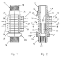
- the flow-control switch device As it can be seen from figures 1, 2 and 3, the flow-control switch device, indicated as a whole by reference 10, comprises a hollow casing 11 of plastic material, moulded in one piece with an inlet threaded pipe fitting 12 and an outlet threaded pipe fitting 13, for the inlet and outlet of a fluid, as shown.
- the casing 11 of the flow-control device is obtained in a single moulding together with the two threaded pipe fittings 12 and 13, by means of plastic material capable of withstanding thermal and mechanical stresses, and hydrolysis, in particular using plastic material suitable for liquid foodstuffs.
- the casing 11 of the flow-control device has a polygonal cross sectional shape, for example hexagonal, provided with a plurality of cross stiffening ribs 14, to make the casing 11 of the device highly resistant to the stresses caused by the water hammering that may occur in a hydraulic circuit when the fluid is suddenly shut off; the polygonal shape of the casing 11 and the stiffening ribs 14, also provide the possibility of removably positioning a reed switch 15 outwardly the same casing, as explained further on.
- the casing 11 of the flow-control switch device comprises a longitudinal duct 16 having an inner cylindrical surface which extends from the inlet threaded pipe fitting 12 to the outlet pipe fitting 13 for the inlet and outlet of the fluid.
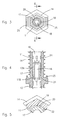
- a movable magnetic element 17 for operating the reed switch 15 is slidably arranged inside the duct 16 to be vertically moved by the fluid thrust and its own weight in the duct 16.
- the movable magnetic element 17, also referred to as "float”, is designed to be entrained by the stream of the fluid which flows through the duct 16; it has an elongated body comprising a fore cylindrical portion 17A, and a rear portion 17B having substantially a conical shape, with the taper facing towards the inlet threaded pipe fitting 12.
- the float 17 has an elongated body provided with an axial hole 18 for the passage of the fluid, and external guiding and centering ribs 19 which extend in a longitudinal direction to the cylindrical portion 17A of the float body; in this way, between the outer surface of the float 17 and the inner surface of the longitudinal duct 16 a narrow annular hollow space 20 is created, which allows the passage of a film of fluid, which together with the guiding ribs 19 makes it possible to reduce the internal friction forces, thereby increasing the sensitivity of the flow-control device.
- the float 17 is obtained by moulding from magnetic plastic material, for example a polymeric material comprising a ferrite filler, or a filler of suitable magnetic material in powder form.
- the magnetic float 17 is permanently magnetised axially along its entire length; in this way it is possible to obtain a magnetic float of reduced dimensions, which is extremely light in weight and therefore highly sensitive to the flow of the fluid, having at the same time a magnetic field strong enough to operate the reed switch 15.
- the body of the float 17 at its rear end is provided with a conical portion 17B which, together with the inner cylindrical surface of the longitudinal duct 16, defines an annular chamber 21 movable with the float itself under the entraining action of the fluid, as shown in the detail of figure 4.
- the diameter of the inner hole of the float 17 can range from 4 to 8 mm, while the angle of the conical part, can range from 10° to 45°.
- figure 5 shows the possibility of making longitudinal slots 22 on the outer surface of the float body 17 to improve the circulation of the fluid film along the annular space 20, and change the operative thresholds of the flow-control device.
- Reference number 23 in figure 2 has been used to indicate a cup-shaped filter in correspondence with the inlet pipe fitting 12; the filter 23 is made in one piece by moulding from plastic material which, in addition to retaining any impurities that may be present in the fluid, constitutes a bottom stop member for the float 17; otherwise, the upper stop member consists of several ribs or protrusions 24 inside the duct 16, as shown in figures 2 and 4.
- the reed switch 15 is removably fitted and/or differently positionable outside the casing 11 of the flow-control device.
- the reed switch 15 comprises a bulb 26 containing the electric contacts that can be magnetically operated by the float 17; the bulb 26 is housed in a plastic container 27, which can be arranged by simply sliding it within the tabs 25;
Abstract
Description
- This invention refers to a magnetically actuated flow-control switch device of vertical float-type, for operating wall-mounted gas-fired boilers, according to the preamble of claim 1. In particular the invention relates to a flow-control device of the aforementioned type, for controlling the ignition of gas-fired boilers for domestic use, designed to indifferently supply both hot water for a heating system and hot water for domestic use.
- In the case of gas-fired wall boilers, each time hot water is required it is necessary to rapidly control the ignition of the burner, as soon as a minimum volume of water begins to flow, after exceeding an operative threshold established by specific regulations or on the basis of requests by the manufacturers.
- Usually, a magnetically actuated flow-control switch device of float-type comprises a tubular body of plastic material or other suitable non magnetically conductive material, defining a longitudinal duct between an inlet pipe fitting and an outlet pipe fitting for the fluid, within which a flow sensing spool comprising a float and a permanent magnet slides; the float is entrained by the flowing fluid to operate a reed-type magnetic switch, providing control signals to control for example the ignition of a gas burner as soon as a light flow of water, caused for example by turning on a tap, or necessary for starting up a circulation pump of the fluid in a heating system, is flowing along the same flow-control device.
- In flow-control device of the aforementioned kind, there are some-times different requirements in contrast with one another, which must be fulfilled without forfeiting the operative reliability and the possibility of an easy installation of the flow-control device in extremely limited spaces.
- A flow -control device of the aforesaid type is described for example in
GB-A-2.243.953 - Other solutions consist of a body made in several parts, comprising threaded or flanged metal pipe fittings at the fluid inlet and outlet ends, as for example shown in
DE-A-3941981 . -
US-A-6.339.959 andUS-A-6.898.984 in turn illustrate flow-control devices comprising a tubular body within which a hollow magnetic float slides; the float is provided with a permanent magnet having an axial hole for the passage of the fluid and comprises a cylindrical outer surface which extends along the entire length, or between annular flanges at the two ends. - Solutions of this kind prove to be unsuitable for a flow-control device designed to be used on small gas-fired wall boilers; in fact, in addition to being structurally complex and consequently more expensive, due to the particular configuration of the tubular body and the float, it is not possible to reduce the overall dimensions of the entire flow-control device, without jeopardising its operative sensitivity and reliability.
- In particular, the limited length of the magnet, necessary to avoid making the float excessively heavy, without jeopardising its sensitivity, has a negative effect on the operative range of the magnet for actuation of the reed switch. Moreover, because of the simple cylindrical or flanged shape of the float, it is not possible to sufficiently reduce and/or modify the operative threshold of the flow control device, without endangering its operative reliability.
- The overall dimensions still remain excessive and unsuitable or somewhat impracticable for flow control devices designed to be fitted into narrow spaces or in wall-mounted boilers of small dimensions.
- The main object of the invention is to provide a float-type flow-control device of the aforementioned type, which is structurally simple and of limited dimensions, while nevertheless maintaining a high degree of sensitivity and operative reliability in controlling a gas-fired boiler.
- A further object of the invention is to provide a float-type flow-control device, whereby it is possible, at the designing, to adapt and/or modify its operative threshold while maintaining the general features and the overall dimensions of the device unchanged.
- A still further object is to provide a float-type flow control device having a high degree of magnetic sensitivity, within a wide operative range of a reed switch, and to replace and/or change the position of the aforesaid reed switch also with the device already assembled in a working line.
- The above can be achieved by means of a flow-control switch device according to claim 1.
- In particular, according to the invention a float-type flow-control switch device has been provided, comprising: a hollow casing of plastic material, defining a longitudinal duct having an inner surface axially extending between an inlet and an outlet for a fluid; a magnetic float sliding within said duct under the entraining action of the fluid, to generate a magnetic field for operation of a reed switch, characterised in that the float has an elongated body having a longitudinal flow hole for the fluid, axially extending between its fore and rear ends; and
- in that said body of the float comprises a fore cylindrical portion, and a rear conical portion defining, together with the inner surface of the longitudinal duct, an annularly shaped thrust chamber movable with the float.
- These and further objects and features of the flow-control switch device according to the invention, will be more clearly evident from the following description of a preferential embodiment, and the accompanying drawings, in which:
- Fig. 1 shows a side view of the flow-control device;
- Fig. 2 shows a longitudinal cross-sectional view of figure 1;
- Fig. 3 shows a cross-sectional view along the line 3-3 of figure 2, with the reed switch removed;
- Fig. 4 shows a detail of figure 2, designed to illustrate the operative principle;
- Fig. 5 shows an enlarged detail of figure 3, relating to a different embodiment of the float.
- As it can be seen from figures 1, 2 and 3, the flow-control switch device, indicated as a whole by
reference 10, comprises ahollow casing 11 of plastic material, moulded in one piece with an inlet threaded pipe fitting 12 and an outlet threaded pipe fitting 13, for the inlet and outlet of a fluid, as shown. - The
casing 11 of the flow-control device is obtained in a single moulding together with the two threadedpipe fittings - The
casing 11 of the flow-control device has a polygonal cross sectional shape, for example hexagonal, provided with a plurality ofcross stiffening ribs 14, to make thecasing 11 of the device highly resistant to the stresses caused by the water hammering that may occur in a hydraulic circuit when the fluid is suddenly shut off; the polygonal shape of thecasing 11 and thestiffening ribs 14, also provide the possibility of removably positioning areed switch 15 outwardly the same casing, as explained further on. - The
casing 11 of the flow-control switch device comprises alongitudinal duct 16 having an inner cylindrical surface which extends from the inlet threaded pipe fitting 12 to the outlet pipe fitting 13 for the inlet and outlet of the fluid. - A movable
magnetic element 17 for operating thereed switch 15 is slidably arranged inside theduct 16 to be vertically moved by the fluid thrust and its own weight in theduct 16. - The movable
magnetic element 17, also referred to as "float", is designed to be entrained by the stream of the fluid which flows through theduct 16; it has an elongated body comprising a forecylindrical portion 17A, and arear portion 17B having substantially a conical shape, with the taper facing towards the inlet threaded pipe fitting 12. - The
float 17 has an elongated body provided with anaxial hole 18 for the passage of the fluid, and external guiding and centeringribs 19 which extend in a longitudinal direction to thecylindrical portion 17A of the float body; in this way, between the outer surface of thefloat 17 and the inner surface of the longitudinal duct 16 a narrow annularhollow space 20 is created, which allows the passage of a film of fluid, which together with the guidingribs 19 makes it possible to reduce the internal friction forces, thereby increasing the sensitivity of the flow-control device. - The
float 17 is obtained by moulding from magnetic plastic material, for example a polymeric material comprising a ferrite filler, or a filler of suitable magnetic material in powder form. - The
magnetic float 17 is permanently magnetised axially along its entire length; in this way it is possible to obtain a magnetic float of reduced dimensions, which is extremely light in weight and therefore highly sensitive to the flow of the fluid, having at the same time a magnetic field strong enough to operate thereed switch 15. - As mentioned previously, the body of the
float 17 at its rear end is provided with aconical portion 17B which, together with the inner cylindrical surface of thelongitudinal duct 16, defines anannular chamber 21 movable with the float itself under the entraining action of the fluid, as shown in the detail of figure 4. - By appropriately choosing, during the designing, the inner diameter of the
hole 18 in the float, and the angle of the conical surface of theportion 17B in respect to the longitudinal axis of the cylindrical body of the float, it is possible to vary the minimum flow rate, or the operative threshold of the flow-control device, both at the beginning and the stop of the circulation of the fluid, and therefore the operative threshold of thereed switch 15. - Purely by way of information, for flow-control switch devices intended for use in small wall-mounted boilers, the diameter of the inner hole of the
float 17 can range from 4 to 8 mm, while the angle of the conical part, can range from 10° to 45°. - From tests carried out, it has been observed that by appropriately choosing the angle of the conical part and of the inner diameter of the
hole 18 in the float, it is possible to obtain minimum operative thresholds for flow rates of about 1,5 to 1,7 litres at the beginning of flow circulation, and of about 2,3 to 2,5 litres during the shut-off, while maintaining a high and constant degree of reliability and operation of the flow-control device. - The detail of figure 5 shows the possibility of making
longitudinal slots 22 on the outer surface of thefloat body 17 to improve the circulation of the fluid film along theannular space 20, and change the operative thresholds of the flow-control device. -
Reference number 23 in figure 2 has been used to indicate a cup-shaped filter in correspondence with theinlet pipe fitting 12; thefilter 23 is made in one piece by moulding from plastic material which, in addition to retaining any impurities that may be present in the fluid, constitutes a bottom stop member for thefloat 17; otherwise, the upper stop member consists of several ribs orprotrusions 24 inside theduct 16, as shown in figures 2 and 4. - In conformity with a further feature of the flow-control switch device according to this invention, the
reed switch 15 is removably fitted and/or differently positionable outside thecasing 11 of the flow-control device. - In particular, as shown in figures 1 and 2, two confronting, and transversally directed, "L"-
shaped tabs 25 are obtained by moulding on one or two opposite faces of thepolygonal casing 11. In turn, thereed switch 15 comprises abulb 26 containing the electric contacts that can be magnetically operated by thefloat 17; thebulb 26 is housed in aplastic container 27, which can be arranged by simply sliding it within thetabs 25; this solution permits an easy assembling and/or replacement of thereed switch 15, in the event of failure or malfunctioning, both before and after the application of the device, without having to interfere with any part of the hydraulic system, the boiler or the equipment on which it has been assembled, thereby facilitating repairs; this solution also makes it possible to easily adapt the choice of the reed switch to different technical requirements of the electronics controlling the equipment. - Whenever heating of the flow meter is required, in place of or in combination with a
reed switch 15 on one side of the flow-control device, it is possible to fit aheating element 28, in acasing 29 with a slide coupling, using theother tabs 25, as shown at the left-hand side of fig. 1. - From what has been described and shown in the accompanying drawings, it will be clear that a magnetic float-type flow-control switch device has been provided, characterised by extreme structural simplicity and a high operative degree and reliability; it is understood however that what has been described and shown in the accompanying drawings has been given purely by way of example in order to illustrate the innovative features of the flow-control device according to the invention. Therefore, other modifications or variations may be made without thereby deviating from the claims, by providing for example both the threaded
pipe fittings hexagonal portions
Claims (15)
- A float-type flow-control switch device comprising:a hollow casing (11) of plastic material, defining a longitudinal duct (16) having an inner surface axially extending between inlet and outlet apertures (12, 13) for a fluid;a magnetic float (17) sliding within said duct (16) under the entraining action of the fluid, to generate a magnetic field for operating a reed switch (26), characterised in that the float (17) has an elongated body having a longitudinal flow hole (18) for the fluid axially extending between fore and rear ends; and in that the body of the float (17) comprises a fore cylindrical portion (17A), and a rear conical portion (17B), the latter defining together with the internal surface of the longitudinal duct (16) an annular by shaped thrust chamber (21) movable with the float.
- The flow-control device according to claim 1, characterised in that the float body (17) is moulded from magnetic plastic material.
- The flow-control device according to claim 1, characterised in that the outer surface of the rear conical portion (17B) of the float (17) defines, with respect to a longitudinal axis of the float (17), an angle ranging from 10° to 45°.
- The flow-control device according to claim 1, characterised in that the diameter of the flow hole (18) of the float (17) is ranging from 4 to 8 mm.
- The flow-control device according to claim 1, characterised by comprising threaded pipe fittings (12, 13) moulded in one piece with the casing (11) of the flow-control device (10), at the fluid inlet and outlet ends.
- The flow-control device according to claim 5, characterised in that each threaded pipe fitting (12, 13) comprises a hexagonal shaped portion (12A, 13A) for engaging with a tightening wrench.
- The flow-control device according to claim 5, characterised in that the fluid inlet and outlet pipe fittings (12, 13) are shaped to engage with different tightening wrenches.
- The flow-control device according to claim 1, characterised in that the outer surface of the float (17) is provided with longitudinal guiding ribs (19).
- The flow-control device according to claim 1, characterised in that the outer surface of the float is provided with longitudinal slots (22).
- The flow-control device according to claim 1, characterised in that the casing (11) of the device (10) is provided with a plurality of stiffening ribs (14).
- The flow-control device according to claim 1, characterised in that the casing (11) of the device (10) has a polygonal shape.
- The flow-control device according to claim 1, characterized in that the reed switch (26) comprises a bulb for electric contacts, inside an housing (27), the casing (11) of the flow-control device (10) being provided, on at least one side, with facing tabs (25) to engage the housing (27) of the reed switch (26).
- The flow-control device according to claim 1, characterised by comprising a cup-shaped filter (23), at the inlet threaded pipe fitting (12), defining a bottom stop member for the float (17).
- The flow-control device according to claim 13, characterised by comprising an upper stop member for the float (17) provide by protrusions (24) inside the longitudinal duct (16).
- The flow-control device according to claim 1, characterised by comprising a removable reed switch (26) on a side, and a removable heating element (28) on another side of the casing (11) of the flow control switch device (10).
Applications Claiming Priority (1)
| Application Number | Priority Date | Filing Date | Title |
|---|---|---|---|
| IT001701A ITMI20051701A1 (en) | 2005-09-15 | 2005-09-15 | FLUSH SWITCH FOR GAS BOILERS OF MURAL TYPE |
Publications (3)
| Publication Number | Publication Date |
|---|---|
| EP1764586A2 true EP1764586A2 (en) | 2007-03-21 |
| EP1764586A3 EP1764586A3 (en) | 2007-04-11 |
| EP1764586B1 EP1764586B1 (en) | 2008-04-23 |
Family
ID=37113771
Family Applications (1)
| Application Number | Title | Priority Date | Filing Date |
|---|---|---|---|
| EP06012503A Not-in-force EP1764586B1 (en) | 2005-09-15 | 2006-06-19 | Flow-control switch device for gas-fired wall boilers |
Country Status (4)
| Country | Link |
|---|---|
| EP (1) | EP1764586B1 (en) |
| AT (1) | ATE393378T1 (en) |
| DE (1) | DE602006000987T2 (en) |
| IT (1) | ITMI20051701A1 (en) |
Cited By (4)
| Publication number | Priority date | Publication date | Assignee | Title |
|---|---|---|---|---|
| WO2011100959A1 (en) * | 2010-02-17 | 2011-08-25 | Meister Strömungstechnik GmbH | Device for monitoring a volumetric flow rate and method for monitoring a volumetric flow rate |
| DE102017111366A1 (en) | 2017-05-24 | 2018-11-29 | Endress+Hauser Conducta Gmbh+Co. Kg | Variable Area Flowmeter |
| CN111029210A (en) * | 2019-12-10 | 2020-04-17 | 安庆中船柴油机有限公司 | Multifunctional marine fuel liquid level switch |
| CN111397673A (en) * | 2020-04-15 | 2020-07-10 | 江苏鑫亚达仪表制造有限公司 | Novel flowmeter sensitive in reaction |
Families Citing this family (1)
| Publication number | Priority date | Publication date | Assignee | Title |
|---|---|---|---|---|
| CN107871641B (en) * | 2016-09-22 | 2020-06-19 | 东莞市东坑合利美电子电器有限公司 | Composition of micro-motion structure of drainage device |
Citations (2)
| Publication number | Priority date | Publication date | Assignee | Title |
|---|---|---|---|---|
| US6339959B1 (en) * | 2000-05-10 | 2002-01-22 | N.M.F. Ltd. | Magnetic float type flowmeter |
| US6898984B2 (en) * | 2002-08-16 | 2005-05-31 | Levitronix Llc | Measuring apparatus to determine the flow of a fluid |
-
2005
- 2005-09-15 IT IT001701A patent/ITMI20051701A1/en unknown
-
2006
- 2006-06-19 AT AT06012503T patent/ATE393378T1/en not_active IP Right Cessation
- 2006-06-19 EP EP06012503A patent/EP1764586B1/en not_active Not-in-force
- 2006-06-19 DE DE602006000987T patent/DE602006000987T2/en active Active
Patent Citations (2)
| Publication number | Priority date | Publication date | Assignee | Title |
|---|---|---|---|---|
| US6339959B1 (en) * | 2000-05-10 | 2002-01-22 | N.M.F. Ltd. | Magnetic float type flowmeter |
| US6898984B2 (en) * | 2002-08-16 | 2005-05-31 | Levitronix Llc | Measuring apparatus to determine the flow of a fluid |
Cited By (4)
| Publication number | Priority date | Publication date | Assignee | Title |
|---|---|---|---|---|
| WO2011100959A1 (en) * | 2010-02-17 | 2011-08-25 | Meister Strömungstechnik GmbH | Device for monitoring a volumetric flow rate and method for monitoring a volumetric flow rate |
| DE102017111366A1 (en) | 2017-05-24 | 2018-11-29 | Endress+Hauser Conducta Gmbh+Co. Kg | Variable Area Flowmeter |
| CN111029210A (en) * | 2019-12-10 | 2020-04-17 | 安庆中船柴油机有限公司 | Multifunctional marine fuel liquid level switch |
| CN111397673A (en) * | 2020-04-15 | 2020-07-10 | 江苏鑫亚达仪表制造有限公司 | Novel flowmeter sensitive in reaction |
Also Published As
| Publication number | Publication date |
|---|---|
| ITMI20051701A1 (en) | 2007-03-16 |
| DE602006000987D1 (en) | 2008-06-05 |
| DE602006000987T2 (en) | 2009-05-28 |
| EP1764586A3 (en) | 2007-04-11 |
| EP1764586B1 (en) | 2008-04-23 |
| ATE393378T1 (en) | 2008-05-15 |
Similar Documents
| Publication | Publication Date | Title |
|---|---|---|
| EP1764586B1 (en) | Flow-control switch device for gas-fired wall boilers | |
| US9593782B2 (en) | Fluid regulator with field convertible slam-shut device | |
| SE468721B (en) | VALVE DEVICE FOR GENERATING SHORT-TERM PRESSURE PULSES EXAMPLE FOR BLEASING BASIC FILTER ELEMENTS | |
| EP2902682B1 (en) | Pilot-operated valve with floating piston | |
| US20070095402A1 (en) | Pressure reducer | |
| US10533307B2 (en) | Fluid governing system | |
| US5169291A (en) | Water heater with shut-off valve | |
| CN100462565C (en) | Automatic pump | |
| EP3973192A1 (en) | A pump controller | |
| JP7108518B2 (en) | Flow control valve in negative pressure wet pre-activation sprinkler system | |
| GB2594320A (en) | Small water heater | |
| US5516077A (en) | Relief valve with integral drain line coupling | |
| JP6194403B2 (en) | Motorized valve | |
| KR950008580Y1 (en) | Flow sensor for gas boiler | |
| EP3693671B1 (en) | Filling system with thermal actuating device | |
| EP1460393B1 (en) | A flow detector with magnetic sensor | |
| US20230417337A1 (en) | Deaerator with integrated shut-off valve | |
| GB2407859A (en) | Condensing boiler assembly with pressure sensor | |
| CN107806724B (en) | Water system protection device, control method, water system and air conditioner | |
| KR100681339B1 (en) | A briquet boiler | |
| KR20170088801A (en) | check valve having magnetization function | |
| JPH0740796Y2 (en) | Steam trap with valve | |
| RU2065670C1 (en) | Electric water heater | |
| KR20110130280A (en) | Flow switch | |
| SE501977C2 (en) | Valve arrangement for controlling pressure medium powder for cleaning filter element - has valve housing forming partly main valve chamber connected to pressure medium source and partly control valve chamber connected to pressure medium source |
Legal Events
| Date | Code | Title | Description |
|---|---|---|---|
| PUAI | Public reference made under article 153(3) epc to a published international application that has entered the european phase |
Free format text: ORIGINAL CODE: 0009012 |
|
| PUAL | Search report despatched |
Free format text: ORIGINAL CODE: 0009013 |
|
| AK | Designated contracting states |
Kind code of ref document: A2 Designated state(s): AT BE BG CH CY CZ DE DK EE ES FI FR GB GR HU IE IS IT LI LT LU LV MC NL PL PT RO SE SI SK TR |
|
| AX | Request for extension of the european patent |
Extension state: AL BA HR MK YU |
|
| AK | Designated contracting states |
Kind code of ref document: A3 Designated state(s): AT BE BG CH CY CZ DE DK EE ES FI FR GB GR HU IE IS IT LI LT LU LV MC NL PL PT RO SE SI SK TR |
|
| AX | Request for extension of the european patent |
Extension state: AL BA HR MK YU |
|
| 17P | Request for examination filed |
Effective date: 20070924 |
|
| 17Q | First examination report despatched |
Effective date: 20071024 |
|
| GRAP | Despatch of communication of intention to grant a patent |
Free format text: ORIGINAL CODE: EPIDOSNIGR1 |
|
| AKX | Designation fees paid |
Designated state(s): AT BE BG CH CY CZ DE DK EE ES FI FR GB GR HU IE IS IT LI LT LU LV MC NL PL PT RO SE SI SK TR |
|
| GRAS | Grant fee paid |
Free format text: ORIGINAL CODE: EPIDOSNIGR3 |
|
| GRAA | (expected) grant |
Free format text: ORIGINAL CODE: 0009210 |
|
| AK | Designated contracting states |
Kind code of ref document: B1 Designated state(s): AT BE BG CH CY CZ DE DK EE ES FI FR GB GR HU IE IS IT LI LT LU LV MC NL PL PT RO SE SI SK TR |
|
| REG | Reference to a national code |
Ref country code: GB Ref legal event code: FG4D |
|
| REG | Reference to a national code |
Ref country code: CH Ref legal event code: EP |
|
| REF | Corresponds to: |
Ref document number: 602006000987 Country of ref document: DE Date of ref document: 20080605 Kind code of ref document: P |
|
| REG | Reference to a national code |
Ref country code: IE Ref legal event code: FG4D Free format text: LANGUAGE OF EP DOCUMENT: FRENCH |
|
| PG25 | Lapsed in a contracting state [announced via postgrant information from national office to epo] |
Ref country code: SI Free format text: LAPSE BECAUSE OF FAILURE TO SUBMIT A TRANSLATION OF THE DESCRIPTION OR TO PAY THE FEE WITHIN THE PRESCRIBED TIME-LIMIT Effective date: 20080423 |
|
| NLV1 | Nl: lapsed or annulled due to failure to fulfill the requirements of art. 29p and 29m of the patents act | ||
| PG25 | Lapsed in a contracting state [announced via postgrant information from national office to epo] |
Ref country code: FI Free format text: LAPSE BECAUSE OF FAILURE TO SUBMIT A TRANSLATION OF THE DESCRIPTION OR TO PAY THE FEE WITHIN THE PRESCRIBED TIME-LIMIT Effective date: 20080423 Ref country code: NL Free format text: LAPSE BECAUSE OF FAILURE TO SUBMIT A TRANSLATION OF THE DESCRIPTION OR TO PAY THE FEE WITHIN THE PRESCRIBED TIME-LIMIT Effective date: 20080423 Ref country code: PT Free format text: LAPSE BECAUSE OF FAILURE TO SUBMIT A TRANSLATION OF THE DESCRIPTION OR TO PAY THE FEE WITHIN THE PRESCRIBED TIME-LIMIT Effective date: 20080923 Ref country code: BG Free format text: LAPSE BECAUSE OF FAILURE TO SUBMIT A TRANSLATION OF THE DESCRIPTION OR TO PAY THE FEE WITHIN THE PRESCRIBED TIME-LIMIT Effective date: 20080723 Ref country code: ES Free format text: LAPSE BECAUSE OF FAILURE TO SUBMIT A TRANSLATION OF THE DESCRIPTION OR TO PAY THE FEE WITHIN THE PRESCRIBED TIME-LIMIT Effective date: 20080803 |
|
| PG25 | Lapsed in a contracting state [announced via postgrant information from national office to epo] |
Ref country code: LV Free format text: LAPSE BECAUSE OF FAILURE TO SUBMIT A TRANSLATION OF THE DESCRIPTION OR TO PAY THE FEE WITHIN THE PRESCRIBED TIME-LIMIT Effective date: 20080423 Ref country code: PL Free format text: LAPSE BECAUSE OF FAILURE TO SUBMIT A TRANSLATION OF THE DESCRIPTION OR TO PAY THE FEE WITHIN THE PRESCRIBED TIME-LIMIT Effective date: 20080423 Ref country code: AT Free format text: LAPSE BECAUSE OF FAILURE TO SUBMIT A TRANSLATION OF THE DESCRIPTION OR TO PAY THE FEE WITHIN THE PRESCRIBED TIME-LIMIT Effective date: 20080423 |
|
| PG25 | Lapsed in a contracting state [announced via postgrant information from national office to epo] |
Ref country code: IS Free format text: LAPSE BECAUSE OF FAILURE TO SUBMIT A TRANSLATION OF THE DESCRIPTION OR TO PAY THE FEE WITHIN THE PRESCRIBED TIME-LIMIT Effective date: 20080823 |
|
| PG25 | Lapsed in a contracting state [announced via postgrant information from national office to epo] |
Ref country code: CZ Free format text: LAPSE BECAUSE OF FAILURE TO SUBMIT A TRANSLATION OF THE DESCRIPTION OR TO PAY THE FEE WITHIN THE PRESCRIBED TIME-LIMIT Effective date: 20080423 Ref country code: MC Free format text: LAPSE BECAUSE OF NON-PAYMENT OF DUE FEES Effective date: 20080630 Ref country code: DK Free format text: LAPSE BECAUSE OF FAILURE TO SUBMIT A TRANSLATION OF THE DESCRIPTION OR TO PAY THE FEE WITHIN THE PRESCRIBED TIME-LIMIT Effective date: 20080423 Ref country code: SE Free format text: LAPSE BECAUSE OF FAILURE TO SUBMIT A TRANSLATION OF THE DESCRIPTION OR TO PAY THE FEE WITHIN THE PRESCRIBED TIME-LIMIT Effective date: 20080723 Ref country code: LT Free format text: LAPSE BECAUSE OF FAILURE TO SUBMIT A TRANSLATION OF THE DESCRIPTION OR TO PAY THE FEE WITHIN THE PRESCRIBED TIME-LIMIT Effective date: 20080423 |
|
| EN | Fr: translation not filed | ||
| PG25 | Lapsed in a contracting state [announced via postgrant information from national office to epo] |
Ref country code: SK Free format text: LAPSE BECAUSE OF FAILURE TO SUBMIT A TRANSLATION OF THE DESCRIPTION OR TO PAY THE FEE WITHIN THE PRESCRIBED TIME-LIMIT Effective date: 20080423 Ref country code: RO Free format text: LAPSE BECAUSE OF FAILURE TO SUBMIT A TRANSLATION OF THE DESCRIPTION OR TO PAY THE FEE WITHIN THE PRESCRIBED TIME-LIMIT Effective date: 20080423 Ref country code: BE Free format text: LAPSE BECAUSE OF FAILURE TO SUBMIT A TRANSLATION OF THE DESCRIPTION OR TO PAY THE FEE WITHIN THE PRESCRIBED TIME-LIMIT Effective date: 20080423 |
|
| PLBE | No opposition filed within time limit |
Free format text: ORIGINAL CODE: 0009261 |
|
| STAA | Information on the status of an ep patent application or granted ep patent |
Free format text: STATUS: NO OPPOSITION FILED WITHIN TIME LIMIT |
|
| 26N | No opposition filed |
Effective date: 20090126 |
|
| REG | Reference to a national code |
Ref country code: IE Ref legal event code: MM4A |
|
| PG25 | Lapsed in a contracting state [announced via postgrant information from national office to epo] |
Ref country code: IE Free format text: LAPSE BECAUSE OF NON-PAYMENT OF DUE FEES Effective date: 20080619 Ref country code: FR Free format text: LAPSE BECAUSE OF FAILURE TO SUBMIT A TRANSLATION OF THE DESCRIPTION OR TO PAY THE FEE WITHIN THE PRESCRIBED TIME-LIMIT Effective date: 20090227 Ref country code: EE Free format text: LAPSE BECAUSE OF FAILURE TO SUBMIT A TRANSLATION OF THE DESCRIPTION OR TO PAY THE FEE WITHIN THE PRESCRIBED TIME-LIMIT Effective date: 20080423 |
|
| PG25 | Lapsed in a contracting state [announced via postgrant information from national office to epo] |
Ref country code: LU Free format text: LAPSE BECAUSE OF NON-PAYMENT OF DUE FEES Effective date: 20080619 Ref country code: HU Free format text: LAPSE BECAUSE OF FAILURE TO SUBMIT A TRANSLATION OF THE DESCRIPTION OR TO PAY THE FEE WITHIN THE PRESCRIBED TIME-LIMIT Effective date: 20081024 Ref country code: CY Free format text: LAPSE BECAUSE OF FAILURE TO SUBMIT A TRANSLATION OF THE DESCRIPTION OR TO PAY THE FEE WITHIN THE PRESCRIBED TIME-LIMIT Effective date: 20080423 |
|
| PG25 | Lapsed in a contracting state [announced via postgrant information from national office to epo] |
Ref country code: TR Free format text: LAPSE BECAUSE OF FAILURE TO SUBMIT A TRANSLATION OF THE DESCRIPTION OR TO PAY THE FEE WITHIN THE PRESCRIBED TIME-LIMIT Effective date: 20080423 |
|
| PG25 | Lapsed in a contracting state [announced via postgrant information from national office to epo] |
Ref country code: GR Free format text: LAPSE BECAUSE OF FAILURE TO SUBMIT A TRANSLATION OF THE DESCRIPTION OR TO PAY THE FEE WITHIN THE PRESCRIBED TIME-LIMIT Effective date: 20080724 |
|
| REG | Reference to a national code |
Ref country code: CH Ref legal event code: PL |
|
| GBPC | Gb: european patent ceased through non-payment of renewal fee |
Effective date: 20100619 |
|
| PG25 | Lapsed in a contracting state [announced via postgrant information from national office to epo] |
Ref country code: CH Free format text: LAPSE BECAUSE OF NON-PAYMENT OF DUE FEES Effective date: 20080630 Ref country code: LI Free format text: LAPSE BECAUSE OF NON-PAYMENT OF DUE FEES Effective date: 20080630 |
|
| PG25 | Lapsed in a contracting state [announced via postgrant information from national office to epo] |
Ref country code: LI Free format text: LAPSE BECAUSE OF NON-PAYMENT OF DUE FEES Effective date: 20100630 Ref country code: CH Free format text: LAPSE BECAUSE OF NON-PAYMENT OF DUE FEES Effective date: 20100630 |
|
| PG25 | Lapsed in a contracting state [announced via postgrant information from national office to epo] |
Ref country code: GB Free format text: LAPSE BECAUSE OF NON-PAYMENT OF DUE FEES Effective date: 20100619 |
|
| PGFP | Annual fee paid to national office [announced via postgrant information from national office to epo] |
Ref country code: DE Payment date: 20120620 Year of fee payment: 7 |
|
| PGFP | Annual fee paid to national office [announced via postgrant information from national office to epo] |
Ref country code: IT Payment date: 20120629 Year of fee payment: 7 |
|
| REG | Reference to a national code |
Ref country code: DE Ref legal event code: R082 Ref document number: 602006000987 Country of ref document: DE Representative=s name: MAIWALD PATENTANWALTS GMBH, DE |
|
| REG | Reference to a national code |
Ref country code: DE Ref legal event code: R119 Ref document number: 602006000987 Country of ref document: DE Effective date: 20140101 |
|
| PG25 | Lapsed in a contracting state [announced via postgrant information from national office to epo] |
Ref country code: DE Free format text: LAPSE BECAUSE OF NON-PAYMENT OF DUE FEES Effective date: 20140101 |
|
| PG25 | Lapsed in a contracting state [announced via postgrant information from national office to epo] |
Ref country code: IT Free format text: LAPSE BECAUSE OF NON-PAYMENT OF DUE FEES Effective date: 20130619 |