EP1764569B1 - Accumulateur avec un élément sécheur-filtre pour un condenseur - Google Patents
Accumulateur avec un élément sécheur-filtre pour un condenseur Download PDFInfo
- Publication number
- EP1764569B1 EP1764569B1 EP05020305.8A EP05020305A EP1764569B1 EP 1764569 B1 EP1764569 B1 EP 1764569B1 EP 05020305 A EP05020305 A EP 05020305A EP 1764569 B1 EP1764569 B1 EP 1764569B1
- Authority
- EP
- European Patent Office
- Prior art keywords
- dryer
- filter unit
- receiver tank
- refrigerant
- region
- Prior art date
- Legal status (The legal status is an assumption and is not a legal conclusion. Google has not performed a legal analysis and makes no representation as to the accuracy of the status listed.)
- Expired - Fee Related
Links
Images


Classifications
-
- F—MECHANICAL ENGINEERING; LIGHTING; HEATING; WEAPONS; BLASTING
- F25—REFRIGERATION OR COOLING; COMBINED HEATING AND REFRIGERATION SYSTEMS; HEAT PUMP SYSTEMS; MANUFACTURE OR STORAGE OF ICE; LIQUEFACTION SOLIDIFICATION OF GASES
- F25B—REFRIGERATION MACHINES, PLANTS OR SYSTEMS; COMBINED HEATING AND REFRIGERATION SYSTEMS; HEAT PUMP SYSTEMS
- F25B43/00—Arrangements for separating or purifying gases or liquids; Arrangements for vaporising the residuum of liquid refrigerant, e.g. by heat
- F25B43/003—Filters
-
- F—MECHANICAL ENGINEERING; LIGHTING; HEATING; WEAPONS; BLASTING
- F25—REFRIGERATION OR COOLING; COMBINED HEATING AND REFRIGERATION SYSTEMS; HEAT PUMP SYSTEMS; MANUFACTURE OR STORAGE OF ICE; LIQUEFACTION SOLIDIFICATION OF GASES
- F25B—REFRIGERATION MACHINES, PLANTS OR SYSTEMS; COMBINED HEATING AND REFRIGERATION SYSTEMS; HEAT PUMP SYSTEMS
- F25B2339/00—Details of evaporators; Details of condensers
- F25B2339/04—Details of condensers
- F25B2339/044—Condensers with an integrated receiver
- F25B2339/0441—Condensers with an integrated receiver containing a drier or a filter
-
- F—MECHANICAL ENGINEERING; LIGHTING; HEATING; WEAPONS; BLASTING
- F25—REFRIGERATION OR COOLING; COMBINED HEATING AND REFRIGERATION SYSTEMS; HEAT PUMP SYSTEMS; MANUFACTURE OR STORAGE OF ICE; LIQUEFACTION SOLIDIFICATION OF GASES
- F25B—REFRIGERATION MACHINES, PLANTS OR SYSTEMS; COMBINED HEATING AND REFRIGERATION SYSTEMS; HEAT PUMP SYSTEMS
- F25B39/00—Evaporators; Condensers
- F25B39/04—Condensers
Definitions
- the invention relates to a collector with dryer / filter unit for a heat exchanger, in particular a capacitor, as used for example for the air conditioning of a motor vehicle.
- EP-A-1 533 580 is a refrigerant condenser known, but does not have a dryer / filter unit.
- a refrigerant condenser with a tube / fin block and manifolds wherein one of the manifolds is formed in two parts and consists of a pipe end receiving the bottom part and a cover part.
- a collector Parallel to the manifold, a collector is arranged, wherein between the manifold and collector, a gap is provided.
- two overflow openings are provided in the lower region, so that they are in fluid communication with each other.
- a dividing wall is arranged in the collecting pipe between the two overflow openings.
- a dryer / filter unit which is open over its circumference is used, which is fastened in a groove of the collector by means of a holding means, such as a circumferential holding rib.
- the collector is down and up closed by a lid.
- the collector is designed as a one-piece tube.
- the dryer / filter unit Due to contamination in the refrigerant circuit due to undesired partial conversion of the oil as a result of thermal and / or mechanical stresses and / or graphite, the dryer / filter unit can clog, especially in the lower forced flow area, so that the power decreases. If the contamination is not collected in the granulate bed in the Trvckner- / filter unit, it may come to accumulation of contamination on the expansion valve, whereby its function is impaired, in particular by the deterioration of the moving parts thereof as a result of ablagemden pollution. Such an air conditioning system leaves nothing to be desired, especially with regard to the durability of the power.
- a collector is provided with at least one dryer / filter unit arranged in the collector, in particular for a condenser, wherein the collector has at least two overflow openings through which a refrigerant can flow in or out, and the dryer / filter unit has at least one free entrance surface through which the inflowing refrigerant can enter the dryer / filter unit, and at least a free exit surface, through which the refrigerant from the tracker / filter unit can flow, wherein between the free entrance surface and the free exit surface at least one element for preventing the refrigerant is arranged on an outside flow around the dryer / filter unit in the collector.
- the dryer / filter unit is formed closed over at least a portion so that a distance between the free entrance surface and the free exit surface is greater than a distance between the two overflow openings, wherein particularly preferably the closed formed portion at least in the region of the height of the overflow is arranged, through which the refrigerant in the collector and / or can flow out.
- the term "height” here does not necessarily refer exclusively to a vertical direction but also encompasses other orientations, in particular horizontal orientations, so that a lateral flow around the closed area takes place.
- the closed area can be flowed around with appropriate configuration also downwards, although a flow upwards should be the rule.
- the closed-formed area of the dryer / filter unit is preferably directly adjacent to the element for preventing the refrigerant at one Flow around the dryer / filter booklet arranged.
- This element can be formed by a sealing lip or by a retaining rib and prevents at least partially an outside flow around the dryer / filter unit.
- the free entrance surface is greater than or at least equal to the free exit area of the dryer / filter unit. This ensures a large entrance surface and thus a large-area filter surface.
- the free entrance area is at least twice as large as the free exit area.
- the height of the closed design of the dryer / filter unit in the region of the height of the refrigerant introducing the overflow opening is preferably at least 20 mm.
- the closed area of the dryer / filter booklet is preferably formed by a wall formed on the truckner / filter unit.
- the wall is particularly preferably formed as a hollow cylinder.
- the wall of the dryer / filter unit in conjunction with the inner circumferential surface of the collector form an annular gap, in particular preferably with a constant gap width.
- annular gap inflowing refrigerant is distributed over the entire circumference and also conveyed in the longitudinal direction, wherein due to the fluidically suitable design only a minimal pressure loss occurs.
- the free entrance surface is arranged spatially above the free exit surface of the dryer / filter unit, so that liquid refrigerant is retained.
- At the closed formed portion of the dryer / filter unit at least one element is preferably provided, which centers the dryer / filter unit in the collector. Distributed over the circumference are preferably provided at least three corresponding elements, wherein over the length of the dryer / filter unit also several, in particular two such centering arrangements of corresponding elements are provided, in particular in closed areas.
- the elements are preferably formed by ribs extending in the longitudinal direction of the dryer / filter unit. These can be rounded off for easier insertion and removal of the dryer / filter unit.
- a second closed area is preferably formed above the free entrance surface, through which the refrigerant flows into the dryer / filter unit. This preferably has the same height as the first closed area.
- Granules are preferably provided in the dryer / filter unit, but another suitable filter material, such as, for example, a fabric, may also be provided.
- Such a collector with dryer / filter unit is preferably used in a heat exchanger, in particular a condenser, which serves the air conditioning of a motor vehicle.
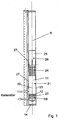
- a capacitor 1 the basic structure - unless otherwise expressly described below - that of in Fig. 3 illustrated, the first embodiment of DE 103 38 527 A1 corresponds, in particular with regard to the configuration of the fluid connection between the manifold and a collector, in which a dryer / filter unit is arranged, and the fixation of the dryer / filter unit is arranged in a refrigerant circuit (not shown), in which as refrigerant R134a is circulated.
- the condenser 1 has a tube / rib block 2, which is formed by flat tubes 3 and corrugated ribs 4 arranged between them.
- the ends of the flat tubes 3 open into a respective manifold 5, wherein in Fig. 3 only the right manifold is shown.
- two overflow openings 8, 9 are provided for a fluid connection of manifold 5 and collector 6, wherein for the reversal of the refrigerant flow, a partition wall 10 in the manifold 5 between the two overflow openings 8 and 9 is arranged.
- a dryer / filter unit 11 is inserted, which by means of a circumferential retaining rib 12 which engages in a groove 13 in the collector 6 is attached.
- the collector 6 is closed at the top and bottom with lids 14.
- the dryer / filter unit 11 is formed in the region above the holding rib 12 over its entire circumference and part of its length closed with a wall 20 which is attached to the grid.
- the wall 20 is also referred to below as the first closed region 21.
- a sealing lip 22 is provided which in sealing engagement with the inner circumferential surface of the collector. 6 is.
- the space between the retaining rib 12 and the sealing lip 22 may be used for storing liquid refrigerant which accumulates at the bottom due to gravity.
- retaining rib and sealing lip are arranged reversed around, the wall extending to the sealing lip. This arrangement ensures that no refrigerant, bypassing a substantial part of the dryer / filter unit 11, takes the shorter path from the overflow opening 8 to the overflow opening 9.
- the outer diameter of the wall 20 is smaller than the inner diameter of the collector 6, so that between the wall 20 and the inner circumferential surface of the collector 6 remains an annular gap 23, flows through soft refrigerant flowing through the overflow 8, over the entire circumference of the annular gap 23 distributed and flows upwards.
- the corresponding area through which the refrigerant flows after flowing through the overflow opening 8 and before entering the dryer / filter unit 11 is also referred to below as the inflow and distribution area of the collector 6.
- the wall 20 covers an area of the dryer / filter unit 11, which corresponds to between a quarter and a third of the total cylindrical area of the dryer / filter unit 11.
- an open area 24 follows, also referred to below as the entry area of the dryer / filter unit 11, which has approximately the same length as the wall 20.
- a second closed area 26 which is surrounded by a further, second wall 25 over its circumference, is again provided, which has approximately the same length as the first closed area 21.
- support ribs 27 are formed over the circumference of the walls 20 and 25, which provide for the centering of the dryer / filter unit 11 in the collector 6 and thus for a constant annular gap 23.
- the support ribs 27 are rounded, so that a simple insertion of the TrocKner- / filter unit 11 is possible, wherein the support ribs 27 are each arranged in the vicinity of the free area 24, ie they are shifted in their longitudinal direction up or down.
- the three levels, in which the retaining rib 12 and the support ribs 27 are provided, are distributed relatively uniformly over the entire length of the drying / filter unit 11.
- a further open area 28, hereinafter also referred to as the outlet area of the dryer / filter unit 11, is provided, which in the present case is approximately half as long as the entry area.
- a collecting and outflow area of the collector 6 is arranged around the inlet area and below it.
- the refrigerant is distributed in the annular gap 23 and flows upward until the wall 20 ends.
- it can penetrate over the first, open region 24, namely the entry surface, into the dryer / fitter unit 11 over a large area and, while flowing through the granules arranged therein, down to the second, open region 28, ie to the exit surface and into the collecting and outflow region of the collector 6, from where it passes through the second, lower overflow 9 again in the manifold 5, but in the arranged below the partition wall 12, passes.
Claims (11)
- Collecteur comprenant au moins un ensemble filtre déshydrateur disposé dans le collecteur (6), en particulier pour un condenseur (1), où le collecteur (6) présente au moins deux ouvertures de trop-plein (8, 9) par lesquelles un fluide frigorigène peut entrer ou sortir, et l'ensemble filtre déshydrateur présente au moins une surface d'entrée libre (24), par laquelle le fluide frigorigène entrant peut parvenir dans l'ensemble filtre déshydrateur (11), et présente au moins une surface de sortie libre (28) par laquelle le fluide frigorigène peut sortir de l'ensemble filtre déshydrateur (11), où au moins un élément (12) est disposé entre la surface d'entrée libre (24) et la surface de sortie libre (28), ledit élément servant à empêcher le fluide frigorigène de s'écouler extérieurement autour de l'ensemble filtre déshydrateur (11) placé dans le collecteur (6), où l'ensemble filtre déshydrateur (11) est configuré en étant fermé sur au moins une zone partielle, de sorte qu'un espacement entre la surface d'entrée libre (24) et la surface de sortie libre (28) est plus grand qu'un espacement compris entre les deux ouvertures de trop-plein (8, 9), caractérisé en ce que la zone de l'ensemble filtre déshydrateur (11), configurée en étant fermée, est disposée en étant directement voisine de l'élément (12) servant à empêcher le fluide frigorigène de s'écouler autour de l'ensemble filtre déshydrateur (11), en ce que l'élément (12) servant à empêcher le fluide frigorigène de s'écouler autour de l'ensemble filtre déshydrateur (11) est formé par une nervure circulaire (12) ou par une lèvre d'étanchéité, et en ce que la surface d'entrée libre (24) est plus grande que la surface de sortie libre (28) de l'ensemble filtre déshydrateur (11).
- Collecteur comprenant un ensemble filtre déshydrateur selon la revendication 1, caractérisé en ce que la zone partielle de l'ensemble filtre déshydrateur, configurée en étant fermée, est disposée au moins dans la zone située à hauteur de l'ouverture de trop-plein (8), ouverture par laquelle le fluide frigorigène peut entrer dans le collecteur (6).
- Collecteur comprenant un ensemble filtre déshydrateur selon la revendication 1 ou 2, caractérisé en ce que la zone partielle de l'ensemble filtre déshydrateur, configurée en étant fermée, est disposée au moins dans la zone située à hauteur de l'ouverture de trop-plein (9), ouverture par laquelle le fluide frigorigène peut sortir du collecteur (6).
- Collecteur comprenant un ensemble filtre déshydrateur selon l'une quelconque des revendications précédentes, caractérisé en ce que la zone de l'ensemble filtre déshydrateur (11), configurée en étant fermée, est formée par une paroi (20) qui est configurée sur l'ensemble filtre déshydrateur (11).
- Collecteur comprenant un ensemble filtre déshydrateur selon la revendication 4, caractérisé en ce que la paroi (20) de l'ensemble filtre déshydrateur (11) forme, en association avec la surface latérale intérieure du collecteur (6), une fente annulaire (23).
- Collecteur comprenant un filtre déshydrateur selon l'une quelconque des revendications précédentes, caractérisé en ce que la surface d'entrée libre (24) est disposée, physiquement, au-dessus de la surface de sortie libre (28) de l'ensemble filtre déshydrateur (11).
- Collecteur comprenant un ensemble filtre déshydrateur selon l'une quelconque des revendications précédentes, caractérisé en ce qu'il est prévu, au niveau de la zone partielle de l'ensemble filtre déshydrateur (11), configurée en étant fermée, au moins un élément qui centre l'ensemble filtre déshydrateur (11) dans le collecteur (6).
- Collecteur comprenant un ensemble filtre déshydrateur selon la revendication 7, caractérisé en ce que l'élément est formé par au moins trois nervures (27) réparties sur la circonférence et s'étendant dans le sens de la longueur de l'ensemble filtre déshydrateur (11).
- Collecteur comprenant un ensemble filtre déshydrateur selon l'une quelconque des revendications précédentes, caractérisé en ce qu'une deuxième zone fermée (26) est configurée au-dessus de la surface d'entrée libre (24).
- Collecteur comprenant un ensemble filtre déshydrateur selon l'une quelconque des revendications précédentes, caractérisé en ce qu'il est prévu un granulat dans l'ensemble filtre déshydrateur (11).
- Echangeur de chaleur, en particulier condenseur, présentant au moins un tube collecteur (5) et un collecteur (6) relié au tube collecteur (5) par au moins deux ouvertures de trop-plein (8, 9), collecteur dans lequel est disposé un ensemble filtre déshydrateur (11), caractérisé en ce que l'échangeur de chaleur (1) présente au moins un collecteur (6) comprenant un ensemble filtre déshydrateur (11) selon l'une quelconque des revendications précédentes.
Priority Applications (1)
| Application Number | Priority Date | Filing Date | Title |
|---|---|---|---|
| EP05020305.8A EP1764569B1 (fr) | 2005-09-16 | 2005-09-16 | Accumulateur avec un élément sécheur-filtre pour un condenseur |
Applications Claiming Priority (1)
| Application Number | Priority Date | Filing Date | Title |
|---|---|---|---|
| EP05020305.8A EP1764569B1 (fr) | 2005-09-16 | 2005-09-16 | Accumulateur avec un élément sécheur-filtre pour un condenseur |
Publications (2)
| Publication Number | Publication Date |
|---|---|
| EP1764569A1 EP1764569A1 (fr) | 2007-03-21 |
| EP1764569B1 true EP1764569B1 (fr) | 2013-11-27 |
Family
ID=35262142
Family Applications (1)
| Application Number | Title | Priority Date | Filing Date |
|---|---|---|---|
| EP05020305.8A Expired - Fee Related EP1764569B1 (fr) | 2005-09-16 | 2005-09-16 | Accumulateur avec un élément sécheur-filtre pour un condenseur |
Country Status (1)
| Country | Link |
|---|---|
| EP (1) | EP1764569B1 (fr) |
Families Citing this family (2)
| Publication number | Priority date | Publication date | Assignee | Title |
|---|---|---|---|---|
| CN201852383U (zh) | 2010-11-17 | 2011-06-01 | 浙江三花汽车控制系统有限公司 | 一种热交换器及其贮液器 |
| EP3112778B1 (fr) * | 2015-06-29 | 2018-01-17 | MAHLE International GmbH | Condensateur |
Family Cites Families (4)
| Publication number | Priority date | Publication date | Assignee | Title |
|---|---|---|---|---|
| FR2770896B1 (fr) * | 1997-11-10 | 2000-01-28 | Valeo Thermique Moteur Sa | Condenseur de climatisation muni d'un reservoir de fluide a cartouche interchangeable |
| DE10234889A1 (de) * | 2002-07-31 | 2004-02-19 | Behr Gmbh & Co. | Trockner für Kältemittelkondensator |
| DE10353939A1 (de) * | 2003-11-18 | 2005-06-16 | Modine Manufacturing Co., Racine | Kondensator und Herstellungsverfahren |
| US6981389B2 (en) * | 2003-12-12 | 2006-01-03 | Calsonickansei North America, Inc. | Receiver and service cartridge for a condenser system |
-
2005
- 2005-09-16 EP EP05020305.8A patent/EP1764569B1/fr not_active Expired - Fee Related
Also Published As
| Publication number | Publication date |
|---|---|
| EP1764569A1 (fr) | 2007-03-21 |
Similar Documents
| Publication | Publication Date | Title |
|---|---|---|
| EP0669506B1 (fr) | Condenseur pour une installation de climatisation d'un véhicule | |
| EP1724536B1 (fr) | Echangeur de chaleur avec partie accumulatrice | |
| EP2129978B1 (fr) | Condenseur destiné à une climatisation, notamment à une climatisation de véhicule | |
| DE69814235T2 (de) | Verflüssiger mit mehrstufiger Trennung der Gas- und Flüssigkeitsphasen | |
| DE102009023951B3 (de) | Filtereinrichtung zur Flüssigkeitsfiltrierung | |
| EP2378225B1 (fr) | Condensateur pour une climatisation, notamment d'un véhicule automobile | |
| EP1147930B1 (fr) | Condenseur pour la climatisation de véhicule automobile | |
| DE69818488T2 (de) | Sammelbehälter | |
| DE10329297A1 (de) | Kondensatoraggregat mit leicht veränderbarer Volumetrie | |
| DE3117543A1 (de) | "waermetauscher, insbesondere fuer einen kuehlkreislauf eines kraftfahrzeugmotors" | |
| DE19609687C5 (de) | Wandkühlgerät für einen Schaltsschrank mit einem Lüfter und einem Lamellen-Wärmetauscher | |
| DE10009864A1 (de) | Kühlvorrichtung | |
| DE60006776T2 (de) | Verflüssiger mit integriertem Sammler-Trockner | |
| WO2004025195A1 (fr) | Collecteur pour agent refrigerant, echangeur de chaleur, circuit ferme d'agent refrigerant et procede de production d'un collecteur | |
| DE10353160A1 (de) | Wärmetauscher und Sammelbehälter-Trockner-Baugruppe für Wärmetauscher | |
| EP1764569B1 (fr) | Accumulateur avec un élément sécheur-filtre pour un condenseur | |
| EP1623167A1 (fr) | Dispositif pour condenser un agent de refroidissement | |
| DE102004059680B4 (de) | Bauanordnung für Einrichtungen zum Austausch von Wärme | |
| DE102005024158C5 (de) | Trockner für ein Kühlmedium in einem Kühlmedienkreislauf, insbesondere für eine Klimaanlage eines Fahrzeugs | |
| EP1434023B1 (fr) | Sécheur à froid | |
| EP1906114A1 (fr) | Echangeur de chaleur, en particulier condenseur | |
| EP1562010A2 (fr) | Echangeur de chaleur | |
| DE102004055004A1 (de) | Sammelbehälter für einen Wärmetauscher und Wärmetauscher | |
| WO2012098261A2 (fr) | Module condenseur de fluide frigorigène | |
| EP4036510A1 (fr) | Dispositif de refroidissement et de séchage de l'air |
Legal Events
| Date | Code | Title | Description |
|---|---|---|---|
| PUAI | Public reference made under article 153(3) epc to a published international application that has entered the european phase |
Free format text: ORIGINAL CODE: 0009012 |
|
| AK | Designated contracting states |
Kind code of ref document: A1 Designated state(s): AT BE BG CH CY CZ DE DK EE ES FI FR GB GR HU IE IS IT LI LT LU LV MC NL PL PT RO SE SI SK TR |
|
| AX | Request for extension of the european patent |
Extension state: AL BA HR MK YU |
|
| 17P | Request for examination filed |
Effective date: 20070918 |
|
| 17Q | First examination report despatched |
Effective date: 20071018 |
|
| AKX | Designation fees paid |
Designated state(s): DE FR IT |
|
| APBK | Appeal reference recorded |
Free format text: ORIGINAL CODE: EPIDOSNREFNE |
|
| APBN | Date of receipt of notice of appeal recorded |
Free format text: ORIGINAL CODE: EPIDOSNNOA2E |
|
| APBR | Date of receipt of statement of grounds of appeal recorded |
Free format text: ORIGINAL CODE: EPIDOSNNOA3E |
|
| APAF | Appeal reference modified |
Free format text: ORIGINAL CODE: EPIDOSCREFNE |
|
| APBT | Appeal procedure closed |
Free format text: ORIGINAL CODE: EPIDOSNNOA9E |
|
| GRAP | Despatch of communication of intention to grant a patent |
Free format text: ORIGINAL CODE: EPIDOSNIGR1 |
|
| INTG | Intention to grant announced |
Effective date: 20130612 |
|
| GRAS | Grant fee paid |
Free format text: ORIGINAL CODE: EPIDOSNIGR3 |
|
| GRAA | (expected) grant |
Free format text: ORIGINAL CODE: 0009210 |
|
| AK | Designated contracting states |
Kind code of ref document: B1 Designated state(s): DE FR IT |
|
| REG | Reference to a national code |
Ref country code: DE Ref legal event code: R081 Ref document number: 502005014092 Country of ref document: DE Owner name: MAHLE INTERNATIONAL GMBH, DE Free format text: FORMER OWNERS: BEHR GMBH & CO. KG, 70469 STUTTGART, DE; BEHR FRANCE HAMBACH S.A.R.L., HAMBACH, FR |
|
| REG | Reference to a national code |
Ref country code: DE Ref legal event code: R096 Ref document number: 502005014092 Country of ref document: DE Effective date: 20140123 |
|
| REG | Reference to a national code |
Ref country code: DE Ref legal event code: R097 Ref document number: 502005014092 Country of ref document: DE |
|
| PLBE | No opposition filed within time limit |
Free format text: ORIGINAL CODE: 0009261 |
|
| STAA | Information on the status of an ep patent application or granted ep patent |
Free format text: STATUS: NO OPPOSITION FILED WITHIN TIME LIMIT |
|
| 26N | No opposition filed |
Effective date: 20140828 |
|
| REG | Reference to a national code |
Ref country code: DE Ref legal event code: R097 Ref document number: 502005014092 Country of ref document: DE Effective date: 20140828 |
|
| REG | Reference to a national code |
Ref country code: DE Ref legal event code: R082 Ref document number: 502005014092 Country of ref document: DE Representative=s name: GRAUEL, ANDREAS, DIPL.-PHYS. DR. RER. NAT., DE Ref country code: DE Ref legal event code: R081 Ref document number: 502005014092 Country of ref document: DE Owner name: MAHLE INTERNATIONAL GMBH, DE Free format text: FORMER OWNERS: BEHR GMBH & CO. KG, 70469 STUTTGART, DE; BEHR FRANCE HAMBACH S.A.R.L., HAMBACH, FR |
|
| PG25 | Lapsed in a contracting state [announced via postgrant information from national office to epo] |
Ref country code: IT Free format text: LAPSE BECAUSE OF FAILURE TO SUBMIT A TRANSLATION OF THE DESCRIPTION OR TO PAY THE FEE WITHIN THE PRESCRIBED TIME-LIMIT Effective date: 20131127 |
|
| REG | Reference to a national code |
Ref country code: FR Ref legal event code: PLFP Year of fee payment: 12 |
|
| REG | Reference to a national code |
Ref country code: FR Ref legal event code: PLFP Year of fee payment: 13 |
|
| REG | Reference to a national code |
Ref country code: FR Ref legal event code: PLFP Year of fee payment: 14 |
|
| PGFP | Annual fee paid to national office [announced via postgrant information from national office to epo] |
Ref country code: FR Payment date: 20180924 Year of fee payment: 14 |
|
| PGFP | Annual fee paid to national office [announced via postgrant information from national office to epo] |
Ref country code: DE Payment date: 20181001 Year of fee payment: 14 |
|
| REG | Reference to a national code |
Ref country code: DE Ref legal event code: R119 Ref document number: 502005014092 Country of ref document: DE |
|
| PG25 | Lapsed in a contracting state [announced via postgrant information from national office to epo] |
Ref country code: DE Free format text: LAPSE BECAUSE OF NON-PAYMENT OF DUE FEES Effective date: 20200401 |
|
| PG25 | Lapsed in a contracting state [announced via postgrant information from national office to epo] |
Ref country code: FR Free format text: LAPSE BECAUSE OF NON-PAYMENT OF DUE FEES Effective date: 20190930 |