EP1764333A2 - Method and device for spooling a yarn and wound body thus achieved - Google Patents
Method and device for spooling a yarn and wound body thus achieved Download PDFInfo
- Publication number
- EP1764333A2 EP1764333A2 EP06120412A EP06120412A EP1764333A2 EP 1764333 A2 EP1764333 A2 EP 1764333A2 EP 06120412 A EP06120412 A EP 06120412A EP 06120412 A EP06120412 A EP 06120412A EP 1764333 A2 EP1764333 A2 EP 1764333A2
- Authority
- EP
- European Patent Office
- Prior art keywords
- yarn
- spirals
- layers
- forming
- spooling
- Prior art date
- Legal status (The legal status is an assumption and is not a legal conclusion. Google has not performed a legal analysis and makes no representation as to the accuracy of the status listed.)
- Granted
Links
Images


Classifications
-
- B—PERFORMING OPERATIONS; TRANSPORTING
- B65—CONVEYING; PACKING; STORING; HANDLING THIN OR FILAMENTARY MATERIAL
- B65H—HANDLING THIN OR FILAMENTARY MATERIAL, e.g. SHEETS, WEBS, CABLES
- B65H51/00—Forwarding filamentary material
- B65H51/20—Devices for temporarily storing filamentary material during forwarding, e.g. for buffer storage
- B65H51/22—Reels or cages, e.g. cylindrical, with storing and forwarding surfaces provided by rollers or bars
-
- B—PERFORMING OPERATIONS; TRANSPORTING
- B65—CONVEYING; PACKING; STORING; HANDLING THIN OR FILAMENTARY MATERIAL
- B65H—HANDLING THIN OR FILAMENTARY MATERIAL, e.g. SHEETS, WEBS, CABLES
- B65H54/00—Winding, coiling, or depositing filamentary material
- B65H54/76—Depositing materials in cans or receptacles
- B65H54/80—Apparatus in which the depositing device or the receptacle is rotated
-
- B—PERFORMING OPERATIONS; TRANSPORTING
- B65—CONVEYING; PACKING; STORING; HANDLING THIN OR FILAMENTARY MATERIAL
- B65H—HANDLING THIN OR FILAMENTARY MATERIAL, e.g. SHEETS, WEBS, CABLES
- B65H54/00—Winding, coiling, or depositing filamentary material
- B65H54/76—Depositing materials in cans or receptacles
- B65H54/84—Arrangements for compacting materials in receptacles
-
- B—PERFORMING OPERATIONS; TRANSPORTING
- B65—CONVEYING; PACKING; STORING; HANDLING THIN OR FILAMENTARY MATERIAL
- B65H—HANDLING THIN OR FILAMENTARY MATERIAL, e.g. SHEETS, WEBS, CABLES
- B65H55/00—Wound packages of filamentary material
-
- B—PERFORMING OPERATIONS; TRANSPORTING
- B65—CONVEYING; PACKING; STORING; HANDLING THIN OR FILAMENTARY MATERIAL
- B65H—HANDLING THIN OR FILAMENTARY MATERIAL, e.g. SHEETS, WEBS, CABLES
- B65H63/00—Warning or safety devices, e.g. automatic fault detectors, stop-motions ; Quality control of the package
- B65H63/06—Warning or safety devices, e.g. automatic fault detectors, stop-motions ; Quality control of the package responsive to presence of irregularities in running material, e.g. for severing the material at irregularities ; Control of the correct working of the yarn cleaner
-
- B—PERFORMING OPERATIONS; TRANSPORTING
- B65—CONVEYING; PACKING; STORING; HANDLING THIN OR FILAMENTARY MATERIAL
- B65H—HANDLING THIN OR FILAMENTARY MATERIAL, e.g. SHEETS, WEBS, CABLES
- B65H2701/00—Handled material; Storage means
- B65H2701/30—Handled filamentary material
- B65H2701/31—Textiles threads or artificial strands of filaments
Definitions
- the present invention concerns a method and device for spooling yarns, and the wound body thus achieved.
- the cycle to produce yarns in the classical system for cotton, wool and cut fiber in general provides, after the spinning step, the spooling step.
- the yarn contained in a series of cops arriving from the spinning machine is wound, generally onto a spool shaped like a truncated cone or cylindrical, so as to form a pack, commonly called a reel, with predetermined size and weight.
- the yarn wound onto the reel is the method almost universally used to obtain a semi-worked product which can be used more rationally in the subsequent processes, such as doubling, warping, weaving or other, for storing, transporting and selling the yarn.
- the machine that achieves these packs is generally called a spooler, the pack obtained is the reel and the relative operation is spooling.
- the yarn contained in the various cops is knotted one after the other.
- the yarn is subjected to the action of a slub-catcher which, located upstream of the system for winding the yarn, identifies possible defects present in the yarn, cuts the yarn in the defective part and eliminates the segment thus cut.
- the support, or spool is drawn in rotation due to friction by a winding cylinder, on which it rests with a certain pressure.
- the winding cylinder can have, engraved on its surface, helical traversing grooves, on which the yarn slides. The latter is thus wound on the supporting spool in spirals, which gradually cross according to the helixes present on the winding cylinder.
- the formation of the reel with crossed spirals, distributed along the winding zone by using grooved cylinders, has a limit due to the difficulty of controlling the yarn at the points where the travel is inverted and when critical diameters are reached with the formation of overlappings due precisely to the fixed traversing frequency connected to the geometry of the grooved cylindrical.
- the winding cylinder has no groove and the yarn is displaced longitudinally from one end to the other of the spool by means of the action of a thread-guide member independent of the drawing roller, or traversing device, which with an alternate movement crosses the spirals on the spool.
- the yarn is deposited in successive circumferential layers on the spool, thus forming a pack with crossed spirals which gradually assumes a truncated cone or cylindrical shape according to the type of support (spool) used, the shape and disposition of the helixes present on the winding cylinder or the type of alternate longitudinal movement performed by the thread guide member.
- the yarn is also cleaned by means of the slub-catcher which, since it has to cut the yarn in order to eliminate the defect, requires that the reel is stopped and a leading segment of the yarn, wound in the reel, is recovered: this is called the "reel head”. It is necessary to insert the reel head inside a knotting device where it will be joined to a leading segment of the yarn wound on the spool, called the “spool head”, so as to re-establish continuity of the yarn.
- Spooling is then re-started when the join has been made.
- this step we have an acceleration of the reel being formed, with possible slipping and damage to the yarn, entailing an increase of the sizes of the reel and consequently of the weight.
- a first limit is to production.
- the current level of performance of known spoolers, applied for working wool, cotton, synthetic and artificial fibers, and mixes, does not substantially exceed the following parameters:
- the compactness and uniformity of winding are decisive in subsequent steps, such as for example in dyeing, due to the resistance that the yarn opposes to the passage of the dyebath; in fact, the inner layer of the traditional reel generally has a more intense and darker color, and affects hundreds of meters of yarn, while the outer part, which is sequential to the inner part and represents the part with the sample dye, consists of thousands of meters of yarn; or in twisting, in order to improve the working performance thereof and the quality of the twisted yarn obtained; or again in sales, in order to optimize packing, transport and storage.
- the quantity of yarn and the weight of the pack are therefore limited by the variables previously described and by the level of tension which arises on the yarn during the unwinding step, according to the use for which it is intended.
- this packing condition of the spirals mainly entails:
- the purpose of the invention is to perfect a method and achieve a device able to overcome the above limits and disadvantages, obtaining the following advantages:
- Another purpose of the present invention is to obtain a disposition of the spirals which will ensure maximum freedom of movement of the spirals, in both a radial and axial direction, and which will allow to adopt a simplified and cheaper cycle of retraction, volume-giving or dyeing.
- the Applicant has devised, tested and embodied the present invention to overcome the shortcomings of the state of the art and to obtain these and other purposes and advantages.
- the spooling method according to the present invention comprises at least a first unwinding step in which the yarn is unwound from a support member, such as for example a spool, a reel or other, and a second spooling step, in which the yarn is disposed in layers according to a desired order.
- the yarn in the second spooling step is disposed inside a containing means in overlapping layers, each of which consists of a plurality of contiguous spirals of yarn distributed substantially according to the variable geometry of the containing means.
- the spooling device comprises at least a feed unit which unwinds the yarn from the support member, and a forming unit, comprising the containing means and deposition means, configured to distribute the yarn in contiguous spirals according to the geometry of the containing means.
- a so-called wound body is defined as a spooling element, the layers of which are deposited axially one above the other, and not circumferentially around a physical support as happens in the state of the art; said layers have an identical configuration and are without substantial variations in the diameter, or equivalent diameter if the containing means has a non-circular section.
- the solution according to the present invention thus allows to discharge the unwinding tension, due to the speed of unwinding of the yarn from the feed spool or reel, using calender means disposed upstream of the distribution means, and/or on the distribution means itself, with the advantage that it is possible to wind and deposit a yarn that has not been subject to any stress during packing.
- the wound body thus achieved can thus exploit completely the available volumes in the feed creels of the textile machines, for example, weaving machines, knitting machines, retouching machines and dyeing machines, and more generally all processes done downstream of the spooling, with considerable improvements in the performance and relative processing costs.
- Another advantage is that the yarn is always and continuously between the outside and the inside of the wound body due to the effect of the deposition in spirals, so that during the dyeing step the differences in color are eliminated, due to the passage of the dyebath, which occur between the outer and inner layers of traditional reels.
- the characteristic deposition in spirals of the yarn allows to ensure the maximum freedom of movement of the spirals themselves, in both a radial and an axial direction, and to adopt a simplified and cheaper cycle to retract, give volume to or dye the yarn, without needing to form hanks and the subsequent unwinding thereof.
- the dyeing cycle is effected starting directly from the wound body obtained, with qualitative results equal to those of the traditional cycle using hanks.
- the continuous spirals of yarn are disposed around a first axis of rotation "Y" longitudinal and median with respect to said containing means, and substantially misaligned with respect to a second axis "x" on which the spirals are formed.
- the misalignment of the two axes X and Y allows to deposit the yarn with a substantially hypo-cyclical trajectory which defines, central to the wound body, a cylindrical space that can be used for the subsequent handling of the wound body.
- the containing means has a square or rectangular cross section, and consequently has an alternate rectilinear movement with respect to the device that distributes the spirals, or two alternate rectilinear movements orthogonal to each other, and on a plane orthogonal to the plane on which the axis X lies, there will be a deposition of the yarn with a trajectory substantially of the cycloid type, obtaining wound bodies of a cubiform or parallelepiped shape.
- an accumulation step is provided, in which, by means of super-feed/reserve means, an accumulation store of yarn is created to allow the substantially continuous deposition of yarn in the containing means, even during possible steps to replace the spool and/or to detect and eliminate defects in the yarn.
- the segment of defective yarn comprised between the spool and the inlet to the super-feed/reserve means, is stopped; the defective yarn is removed, with the yarn being cut in correspondence with the defect and simultaneously the heads of the yarn being captured directly by the super-feed/reserve means; and the heads of the yarn are knotted.
- the super-feed/reserve means therefore allow not to stop the unwinding of the yarn from the support member as the cylindrical container is changed when the wound body is completed. In fact, during this step feed is stopped to the unit that forms the wound body, but yarn continues to be taken up from the support member in order to form an accumulation of yarn on a drum of the super-feed/reserve unit; this accumulation will later be disposed of when the formation is restarted of the new wound body.
- downstream of the second spooling step at least a step of pressing and tying is provided, in which the overlapping layers consisting of contiguous spirals of yarn are pressed, discharged from the containing means and tied together for packing.
- the pressing operation effected according to the present invention does not interfere on the tension of the yarn and does not weaken its mechanical characteristics.
- the pressing performed allows to increase the density of the wound body, with the advantage that during the forming step the number of layers can be increased for a height of the wound body much greater than that of the desired final height.
- This advantage is particularly important in subsequent steps: packing, transport and logistics in general: in the dyeing step the dyeing apparatus can be loaded with a greater quantity of yarn, as in the feed devices in the subsequent working steps, the knitting machines, warping machines, weaving machines etc.
- the speed at which the yarn is deposited can also be increased, for example said speed can be about 2,000 m/min.
- the present invention therefore overcomes the current limits of spooling speed, due to the tension necessary for winding the yarn onto the reel and the alternate movement of the yarn during the traversing step, thus also reducing production times and costs.
- a spooling device 10 is installed in a spooling machine 11.
- the spooling device 10 substantially comprises a feed unit 12 which picks up the yarn 17 from a spinning spool 13, from one or more reels 15, or from one or more so-called wound bodies 16, the latter for example obtained previously with the method and device 10 according to the present invention, a super-feed/reserve unit 26 which forms a store for feeding yarn 17, a forming unit 32 in which the wound body 16 is formed, and a doffing, pressing and tying device 51 which picks up the wound body 16 formed in the forming unit 32 and prepares it for packing and subsequent working steps.
- the feed unit 12 comprises, in a substantially known manner, a plurality of devices, respectively to control and limit the ballon 19, a tensioner device 20, a thread feeler 21, a knotter 22, a slub-catcher and metering device 23, and possibly a paraffining device 25 and/or thread-gripper.
- the super-feed/reserve unit 26 comprises an accumulation drum 27, upstream and downstream of which there are two groups of calenders, respectively a pick-up calender 29 and an unwinding calender 30, and a deflection calender 31 which introduces the yarn into the forming unit 32.
- the super-feed/reserve unit 26 allows to accumulate a determinate quantity of yarn 17 in the accumulation drum 27, so as to define a store of yarn 17 upstream of the forming unit 32.
- This store allows to feed the forming unit 32 substantially continuously, even when slub-catching operations are carried out, or operations to replace the spinning spool 13, or other operations which normally require the temporary stoppage of the spooling machine 11, thus considerably increasing the performance of the spooling machine 11.
- an alarm signal is emitted and the movement of the pick-up calenders 29 and the accumulation drum 27 is stopped, while the unwinding calenders 30 continue to feed the yarn 17 to the forming unit 32.
- the pick-up calenders 29 normally detect the length of the yarn 17 that has passed through from the moment of the signal to the stoppage of the yarn 17, and invert the direction of rotation in order to remove from the accumulation drum 27 the correct quantity of yarn 17, in which the defect is contained, said length having been memorized during the stoppage.
- two thread-catcher mouths rotate, respectively spool head 24 and reel head 28, intercepting the yarn 17 that is stationary in a position suitable for pick-up.
- the yarn 17 is cut in a known manner by the slub-catcher device 23 in correspondence with the defective segment, which segment is sucked up and removed by the mouth that catches the reel head 28 before being joined with the spool head.
- the knotting device 22 makes the knot and the pick-up calenders 29 restart their normal rotation, increasing the speed in order to reconstitute the store of yarn 17 in the accumulation drum 27.
- the unwinding calenders 30 have fed the forming unit 32 substantially continuously.
- the forming unit 32 comprises two feed calenders 33, a thread-guide channel 36 rotating around a second substantially vertical axis "X", and having a substantially S-shaped development, a distributor plate 37 associated with the thread-guide channel 36 by means of a connection pin 35, and from whose lower periphery the thread-guide channel 36 faces, and a collector plate 39 substantially facing below the distributor plate 37, and rotating around a first vertical axis "Y", in this case misaligned with respect to the second vertical axis "X". If the containing means does not have a circular section, the collector plate 39 will have an alternate rectilinear movement and/or with two directions orthogonal to each other, on a horizontal plane, as explained hereafter.
- the collector plate 39 can be disposed in contact, or with a gap of less than the diameter of the yarn 17 being worked, with respect to the distributor plate 37, so as to exert a slight pressure on the yarn 17 also during the deposition of the first spiral and the formation of the first layer of spirals.
- the thread-guide channel 36 comprises an initial segment coaxial with the second vertical axis "X", a final segment in correspondence with the point where the yarn 17 is distributed, and an inclined intermediate segment which connects the initial segment and the final segment.
- the entity of the orthogonal projection of the intermediate segment on the plane of the distributor plate 37 represents the radius of rotation of the point of distribution of the yarn 17 on the collector plate 39, and also the radius of each spiral of the wound body 16 being formed.
- the spirals made can have a diameter either greater than or smaller than the radius of the collector plate 39.
- the simultaneous rotation of the structure of the distributor plate 37 and the collector plate 39 advantageously in opposite directions, according to the direction of torsion of the yarn 17, and the radius of rotation of the point of distribution, determine the formation of successive layers of spirals of yarn 17, defining a wound body 16 having a substantially cylindrical central hole 42.
- wound body 16 can have sizes, weight and density much greater than those of known reels 15.
- the wound body 16 has the spirals distanced from each other by a pitch equal to about 0.25 mm, that is, the same as the diameter of the yarn 17, whereas due to the effect of the slight pressure exerted by the collector plate 39 on the yarn 17 during the distribution step, the diameter of the yarn 17 is reduced, thus allowing to have a number of layers 117 of spirals 116 such as to determine a specific density greater by more than 70+80% with respect to a reel of the same size obtained with the state of the art.
- the distributor plate 37 advantageously has a lower surface with a mirror finish, so as not to interfere on the yarn 17 deposited, it is provided on the upper part with two calenders 40 to distribute and reduce the tension of the yarn 17, disposed in correspondence with the point of distribution of the yarn 17, and is motorized by means of a drive unit 41 kinematically connected to the thread-guide channel 36.
- both the thread-guide channel 36 and the drive unit 41 are contained inside a protective casing 34.
- the distribution calenders 40 receive motion from corresponding conical rollers 65 which roll on a conical circular track 66 associated at the upper part with the distributor plate 37.
- the conical rollers 65 are coaxial and solid with the calenders 40, so that a revolution of the calenders 40 corresponds with every revolution of the rollers 65.
- the conical rollers 65 tend to move radially due to the centrifugal force, they overcome the resistance of respective return springs 67, opening the gap between the two calenders 40, and thus allow the yarn 17 to exit due to the centrifugal force.
- the distributor plate 37 is associated in co-planar manner with a fixed plate 38, also advantageously having the surface in contact with the yarn 17 mirror finished, and having sizes corresponding to those of the collector plate 39.
- the collector plate 39 advantageously has a high-friction upper surface, for example felted, in order to retain the yarn 17 during the deposition step, and is associated at the lower part with a pneumatic piston 43 which allows it to be selectively moved along the first axis "Y" according to the number of layers of spirals 117 of the wound body 16.
- connection between the pneumatic piston 43 and the collector plate 39 is made advantageously by means of a connection plate 45, provided with an attachment system that allows the simultaneous rotation or translation of the collector plate 39 around the first axis "Y", together with the pneumatic piston 43.
- the collector plate 39 and the pneumatic piston 43 are selectively made to rotate by a relative drive unit 49.
- the collector plate 39 will have the same section as the container 46, it will act with a slight pressure on the yarn 17, exerted by the piston 43 during the collection step, and will have a rectilinear movement such that the spirals of yarn 116 will be deposited with the same pitch or distance from each other, the layer of spirals 117 thus being formed by the alternate movement of the system container 46-collector plate 39.
- the collector plate 39 will have to have a rotation around its first axis "Y" of several revs per minute.
- the descending movement along the first axis "Y" of the collector plate 39 occurs inside a container 46 having inner surfaces able to allow the yarn 17 to slide during the formation of the wound body 16.
- the container 46 rests on a rotary plate 47, coaxial with the collector plate 39 and able to be made to rotate by the same drive unit 49, so as to have substantially the same speed of rotation as the collector plate 39.
- a conveyor belt 50 is provided, advantageously provided with a supporting plate for the cylindrical container 46, and able to selectively move the cylindrical container 46 at least between an inactive position upstream of the forming unit 32, a position for forming the wound body 16 in correspondence with the forming unit 32, and a position for picking up the wound body 16 downstream of the forming unit 32.
- the doffing, pressing and tying device 51 substantially comprises a pressure plate 52, above, moved axially by a first pressure piston 53, and a supporting plate 55, below, on which the cylindrical container 46 slides when the wound body 16 is completely formed.
- the supporting plate 55 is moved axially against the pressure plate 52 by a second pressure piston 56.
- the wound body 16 is picked up, in fact, by means of gripping, in this case vertically, effected by the supporting plate 55 and the pressure plate 52, and the subsequent lifting of the two, when compression is terminated, as far as outside the cylindrical container 46.
- the doffing, pressing and tying device 51 also comprises an upper containing plate 57, disposed to cover the container 46 and substantially co-planar with the pressure plate 52, when the latter is in an inactive position, and a tying device 59 disposed above the upper containing plate 57, and able to position a plurality of tying elements 60 on the wound body 16 so as to temporarily consolidate the layers 117 of spirals of yarn 17 that form it.
- a first discharge belt 61 is provided, disposed substantially at the height of the upper containing plate 57 and able to discharge the tied wound body 16, and a second discharge belt 62, disposed below the cylindrical container 46 and able to transport the latter, once freed of the wound body 16, to the inactive position where it waits to be transported by the conveyor belt 50 to the position for forming the wound body 16.
- the device 10 also comprises a command and control unit 69 of the programmable type and able to manage and coordinate the movements and drives of the various components of the feed unit 12, the super-feed/reserve unit 26, the forming unit 32, and the doffing, pressing and tying device 51, according to desired parameters pre-set and/or pre-settable on each occasion.
- the spooling device 10 functions as follows, in the case of a container 46 with a cylindrical section.
- the collector plate 39 is inside the cylindrical container 46, which in turn rests on the rotary plate 47.
- the collector plate 39 is taken by the pneumatic piston 43 into contact with the lower surface of the distributor plate 37.
- the distributor plate 37 is made to rotate at high speed by the drive unit 41, while the collector plate 39, the cylindrical container 46 and the rotary plate 47 on which the cylindrical container 46 rests are made to rotate at low speed by the drive unit 49.
- the distributor plate 37 and the collector plate 39 rotate in reciprocally opposite directions, according to the direction of torsion of the yarn 17.
- the distributor plate 37 and the collector plate 39 rotate in the same direction.
- the yarn 17 is made to exit from the distributor plate 37 due to the effect of the rotation of the distribution calenders 40, thus starting to deposit in almost circular spirals 116 on the collector plate 39.
- the felted surface of the collector plate 39 retains the first layer of spirals 117 of yarn 17, with respect to the distributor plate 37.
- the subsequent layers will be formed in cooperation between the pressure action of the pneumatic piston 43 and the retaining action that the yarn 17 of the underlying layer exerts on the yarn that is deposited.
- the collector plate 39 is displaced downwards by the piston 43, in any case exerting a desired pressure on the spirals, in order to confer compactness on the wound body 16.
- the pressure exerted by the collector plate 39 on the layers of spirals being formed can be adjusted, so as to render the operation to form the spirals 116 and the layers 117 sure and accurate.
- the pressure also cooperates to determine the final density, defining the number of layers 117 of spirals 116 of which the wound body 16 consists.
- the container 46 will have first a rectilinear horizontal movement along the axis "Y", the spirals 116 will be formed by the rotation of the distributor plate 37 around the axis x and will be deposited on the collector plate 39 which, acting inside the container 46, will also have a rectilinear movement.
- the relation between the speed of rotation of the distributor plate 37 and the speed of translation of the container 46 and the collector plate 39 will determine the pitch of the spirals.
- the container 46 with the wound body 16 formed is taken to its pick-up position, so that the wound body 16 is pressed between the pressure plate 52 and the supporting plate 55, removed from the cylindrical container 46 and then tied by the tying device 59.
- an expeller member thrusts the wound body 16 onto the first discharge belt 61, to send it to subsequent steps, while the cylindrical container 46 is returned to its inactive position by the second discharge belt 62, in order to leave space for a new container 46 with a new wound body 16 which has formed in the meantime.
- the device is configured so as to distribute simultaneously, and substantially in the same way as described above, two yarns in layers 117 of spirals.
- the yarns are deposited in spirals, each separately for an arc of 180° so as not to have reciprocal interference when unwinding, for example during double torsion twisting.
- the separate distribution of the yarns occurs with spirals having a diameter "d" smaller than the semi-diameter "D/2" of the container 46 in which the pack is collected. This allows to form an empty central space 42 of circular shape with characteristics of size suitable to allow to feed the pack to the spindle of the double-torsion twister.
- the device shown in fig. 9 comprises two distribution devices 32a and 32b disposed substantially specular to each other, and substantially identical to the device 32 shown in figs. 2-4; components that are equal or equivalent to those already shown with reference to the previous drawings are given the same reference number, followed by the letter “a” for the device on the left in the drawing, and by the letter “b” for the device on the right, and therefore they will not be described further.
- Each distribution device 32a and 32b is fed with its own yarn, which both distribute the relative yarn on the same collector plate 39 located inside a container 46 in this case cylindrical.
- the cylindrical container 46 will be equipped with an alternate movement of rotation of 180° around the axis Y; in this way, each distribution unit 32a and 32b will deposit on the collector plate 39 layers of spirals 117 obtaining a pack in which the two distinct yarns are available for the subsequent passage in a double-torsion twister in a substantially doubled condition, without any reciprocal interference in the unwinding step.
- the yarn 17 that forms the wound body 16 can be wound inside a cylindrical container 46 provided with a shaft having a diameter a little smaller than the diameter of the central hole 42.
- a pre-loaded helical spring can be provided, or other member able to thrust the collector plate axially upwards during the steps of forming the wound body 16.
- the pre-loaded spring is gradually compressed as the cylindrical container 46 fills with the layers of spirals of yarn 17.
- the spooling device 10 is modular and can be used with other similar spooling devices 10 in the same spooling machine 11.
- an automatic device is provided downstream of the first discharge belt 61, in the zone where the wound bodies 16 are discharged, as an alternative to the pressing and tying step, in order to associate a disk 71 (fig. 8), as a cover, with the cylindrical container which contains the wound body 16, so as to keep the spirals and the yarn 17 controlled and protected during the handling operations.
- a disk 71 (fig. 8), as a cover, with the cylindrical container which contains the wound body 16
- the distribution of the spirals of yarn 17 can be effected according to a plurality of different geometries.
- fig. 7a we have the collector plate 39 with an alternate rectilinear motion with respect to the distributor plate 37, thus forming a wound body 16 of a substantially rectilinear shape
- figs. 7a and 7b we have the collector plate 39 having a quadrangular rectilinear motion with respect to the distributor plate 37, thus forming a wound body 16 with a substantially cubiform shape.
- the containers on which the spirals and layers are deposited in order to obtain the wound body 16 in the alternative solutions shown in figs. 7a-7c must be of the appropriate geometry and size, and also the pressing and tying must follow the most suitable methods for the new forms of wound body 16.
- the cylindrical container 46 has on an outer surface a plurality of through holes 70.
- the collector plate 36 and the possible protective disk 71 are also provided with said through holes 70, so as to allow, in subsequent steps, an easier circulation of the steam or dyebath.
Landscapes
- Engineering & Computer Science (AREA)
- Textile Engineering (AREA)
- Quality & Reliability (AREA)
- Yarns And Mechanical Finishing Of Yarns Or Ropes (AREA)
- Treatment Of Fiber Materials (AREA)
Abstract
Description
- The present invention concerns a method and device for spooling yarns, and the wound body thus achieved.
- The cycle to produce yarns in the classical system for cotton, wool and cut fiber in general provides, after the spinning step, the spooling step.
- During this operation, the yarn contained in a series of cops arriving from the spinning machine is wound, generally onto a spool shaped like a truncated cone or cylindrical, so as to form a pack, commonly called a reel, with predetermined size and weight.
- The yarn wound onto the reel is the method almost universally used to obtain a semi-worked product which can be used more rationally in the subsequent processes, such as doubling, warping, weaving or other, for storing, transporting and selling the yarn.
- The machine that achieves these packs is generally called a spooler, the pack obtained is the reel and the relative operation is spooling.
- During the spooling step the yarn contained in the various cops is knotted one after the other. At the same time, the yarn is subjected to the action of a slub-catcher which, located upstream of the system for winding the yarn, identifies possible defects present in the yarn, cuts the yarn in the defective part and eliminates the segment thus cut. The support, or spool, is drawn in rotation due to friction by a winding cylinder, on which it rests with a certain pressure.
- The winding cylinder can have, engraved on its surface, helical traversing grooves, on which the yarn slides. The latter is thus wound on the supporting spool in spirals, which gradually cross according to the helixes present on the winding cylinder.
- The formation of the reel with crossed spirals, distributed along the winding zone by using grooved cylinders, has a limit due to the difficulty of controlling the yarn at the points where the travel is inverted and when critical diameters are reached with the formation of overlappings due precisely to the fixed traversing frequency connected to the geometry of the grooved cylindrical.
- According to other solutions, the winding cylinder has no groove and the yarn is displaced longitudinally from one end to the other of the spool by means of the action of a thread-guide member independent of the drawing roller, or traversing device, which with an alternate movement crosses the spirals on the spool.
- To prevent the formation of overlappings in correspondence with the critical diameters in the formation of the reel, it is possible to vary the travel of the traversing device, so that the deposition of the yarn on the edges of the reel during the inversion of the traversing device is distributed on a segment of suitable amplitude. By doing this it is possible to limit the tendency of the yarn to be concentrated on the edges, and hence also reduce its density.
- In both ways, the yarn is deposited in successive circumferential layers on the spool, thus forming a pack with crossed spirals which gradually assumes a truncated cone or cylindrical shape according to the type of support (spool) used, the shape and disposition of the helixes present on the winding cylinder or the type of alternate longitudinal movement performed by the thread guide member.
- During the spooling operation, as we said, the yarn is also cleaned by means of the slub-catcher which, since it has to cut the yarn in order to eliminate the defect, requires that the reel is stopped and a leading segment of the yarn, wound in the reel, is recovered: this is called the "reel head". It is necessary to insert the reel head inside a knotting device where it will be joined to a leading segment of the yarn wound on the spool, called the "spool head", so as to re-establish continuity of the yarn.
- Spooling is then re-started when the join has been made. In this step however we have an acceleration of the reel being formed, with possible slipping and damage to the yarn, entailing an increase of the sizes of the reel and consequently of the weight.
- However, the spooling operation on spools, intended as an intermediate or final method to pack the yarn, has intrinsic limits which are not easily overcome, not even by applying the most advanced construction technologies known today.
- A first limit is to production. The current level of performance of known spoolers, applied for working wool, cotton, synthetic and artificial fibers, and mixes, does not substantially exceed the following parameters:
- working speed variable between about 1000 and about 1500 m/min;
- maximum diameter of the reel variable between about 250 and about 300 mm;
- winding density variable between about 0.30 and about 0.45 g/cm';
- tension of yarn during spooling variable between about 15 and about 30 g;
- weight of the reel variable between about 2.5 and about 3.0 kg;
- length of spool (range) variable between about 170 and about 250 mm (max 300 mm);
- winding travel variable between about 152 and about 200 mm; and
- taper variable between about 0° and about 9°15'.
- Moreover, in the subsequent steps, when the yarn is unwound "à la défilée", considerable difficulties occur, mainly due to the circumferential disposition of the layers of yarn on the spool, since the tension on the yarn suffers continual disturbances as the spiral unwinding on the edges of the reel is inverted; it also suffers a variation due to the progressive reduction in the diameter of the reel with a correlated limitation of the unwinding speed.
- Moreover, the compactness and uniformity of winding are decisive in subsequent steps, such as for example in dyeing, due to the resistance that the yarn opposes to the passage of the dyebath; in fact, the inner layer of the traditional reel generally has a more intense and darker color, and affects hundreds of meters of yarn, while the outer part, which is sequential to the inner part and represents the part with the sample dye, consists of thousands of meters of yarn; or in twisting, in order to improve the working performance thereof and the quality of the twisted yarn obtained; or again in sales, in order to optimize packing, transport and storage.
- To increase the density of the yarn in the formed reel there is a tendency to increase the spooling tension beyond determinate limits. This increase in the tension, however, has a negative effect on the resistance of the yarn, causing breakages in correspondence with the weak points of the yarn. Normally, the resistance of the yarn decreases by more than 10% due to the effect of the spooling step.
- The quantity of yarn and the weight of the pack are therefore limited by the variables previously described and by the level of tension which arises on the yarn during the unwinding step, according to the use for which it is intended.
- At present, in order to overcome the limits in forming the reel as indicated above, the producers of spooling machines are moving towards alternative methods in which, by exploiting the possibility offered by variable-speed motorization and by electronics, the traversing speed and the speed of collection of the reel are made dependent on each other.
- However, these alternative methods have the same limits of reel density, yarn tension during the forming of the reel, variation in the tension of the yarn as it unwinds and as the reel diameter varies, dyeing differences between the inside and outside of the reel, different taper for each use of yarn, packaging, movement and logistics in general.
- Another limitation of the formation of the reel with traditional methods, that is, with crossed spirals and wound with a certain tension on a support, or spool, is that the yarn has no possibility of movement in either a radial or axial direction.
- More generally, this packing condition of the spirals mainly entails:
- limited quality as regards dyeing, with the need to adopt a dyeing cycle in hanks, which is very expensive, for all those yarns which have a high quality requirement with regards dyeing, that is, uniformity of dyeing, roundness and volume of the yarn; and
- impossibility of giving volume to yarns for knitwear of the "High Bulk" type directly on the reel, in this case too with the need to adopt a dyeing cycle in hanks, with the relative high economic cost.
- The purpose of the invention is to perfect a method and achieve a device able to overcome the above limits and disadvantages, obtaining the following advantages:
- increase speed and performance of production;
- increase the content of yarn for each reel;
- vary the specific density of the reel according to needs;
- increase the speed and quality of unwinding the yarn maintaining the same tension from beginning to end of the reel;
- improve workability of the yarn in the subsequent steps;
- improve dyeing of the reel, eliminating lack of uniformity of color between inside and outside;
- increase in the dye-house the load of yarn for every dyeing cycle, and hence reduce dyeing costs;
- improve handling of the reel, protecting the yarn contained thereon; and
- increase the specific weight of the packages, hence reducing the costs of storage and transport.
- Another purpose of the present invention is to obtain a disposition of the spirals which will ensure maximum freedom of movement of the spirals, in both a radial and axial direction, and which will allow to adopt a simplified and cheaper cycle of retraction, volume-giving or dyeing.
- The Applicant has devised, tested and embodied the present invention to overcome the shortcomings of the state of the art and to obtain these and other purposes and advantages.
- The present invention is set forth and characterized in the independent claims, while the dependent claims describe other innovative characteristics of the invention.
- In accordance with the above purpose, the spooling method according to the present invention comprises at least a first unwinding step in which the yarn is unwound from a support member, such as for example a spool, a reel or other, and a second spooling step, in which the yarn is disposed in layers according to a desired order.
- According to a characteristic feature of the present invention, in the second spooling step the yarn is disposed inside a containing means in overlapping layers, each of which consists of a plurality of contiguous spirals of yarn distributed substantially according to the variable geometry of the containing means.
- The spooling device according to the present invention comprises at least a feed unit which unwinds the yarn from the support member, and a forming unit, comprising the containing means and deposition means, configured to distribute the yarn in contiguous spirals according to the geometry of the containing means.
- With the method and device according to the present invention, in this way, a so-called wound body is defined as a spooling element, the layers of which are deposited axially one above the other, and not circumferentially around a physical support as happens in the state of the art; said layers have an identical configuration and are without substantial variations in the diameter, or equivalent diameter if the containing means has a non-circular section.
- The limits in size of reels currently produced are thus substantially overcome, both with regard to the diameter and also with regard to the height, and hence with regard to the weight.
- Overcoming these limits advantageously leads to an increase in the density of the yarn which, given the same size, is much greater with respect to the state of the art, since the pitch at which the spirals are deposited, and the distance between two adjacent layers is substantially equal to the diameter of the yarn.
- Moreover, during the geometric distribution of the yarn, no tension is exerted on the yarn, since the yarn is deposited in spirals and not wound around a central support.
- The solution according to the present invention thus allows to discharge the unwinding tension, due to the speed of unwinding of the yarn from the feed spool or reel, using calender means disposed upstream of the distribution means, and/or on the distribution means itself, with the advantage that it is possible to wind and deposit a yarn that has not been subject to any stress during packing.
- Above all, thanks to the characteristic disposition in layers of spirals of the yarn, the latter is always in the best conditions for unwinding without interference with other layers of yarn, as happens with known reels with crossed winding. In this way, it is thus possible to achieve a wound body that is substantially cylindrical, cubiform or parallelepiped, that is, according to the shape of the containing means and hence according to the movement of the latter with respect to the distribution device. This distribution movement can be respectively circular, alternate rectilinear or a combination of the two movements, circular and rectilinear. The wound body thus achieved can thus exploit completely the available volumes in the feed creels of the textile machines, for example, weaving machines, knitting machines, retouching machines and dyeing machines, and more generally all processes done downstream of the spooling, with considerable improvements in the performance and relative processing costs.
- Another advantage is that the yarn is always and continuously between the outside and the inside of the wound body due to the effect of the deposition in spirals, so that during the dyeing step the differences in color are eliminated, due to the passage of the dyebath, which occur between the outer and inner layers of traditional reels.
- Moreover, the characteristic deposition in spirals of the yarn, obtained with the method and device according to the present invention, allows to ensure the maximum freedom of movement of the spirals themselves, in both a radial and an axial direction, and to adopt a simplified and cheaper cycle to retract, give volume to or dye the yarn, without needing to form hanks and the subsequent unwinding thereof. This is possible because with the present invention the dyeing cycle is effected starting directly from the wound body obtained, with qualitative results equal to those of the traditional cycle using hanks.
- According to a preferential form of embodiment of the present invention, the continuous spirals of yarn are disposed around a first axis of rotation "Y" longitudinal and median with respect to said containing means, and substantially misaligned with respect to a second axis "x" on which the spirals are formed.
- The misalignment of the two axes X and Y allows to deposit the yarn with a substantially hypo-cyclical trajectory which defines, central to the wound body, a cylindrical space that can be used for the subsequent handling of the wound body.
- If the containing means has a square or rectangular cross section, and consequently has an alternate rectilinear movement with respect to the device that distributes the spirals, or two alternate rectilinear movements orthogonal to each other, and on a plane orthogonal to the plane on which the axis X lies, there will be a deposition of the yarn with a trajectory substantially of the cycloid type, obtaining wound bodies of a cubiform or parallelepiped shape.
- According to another preferential form of embodiment, between the first unwinding step and the second spooling step at least an accumulation step is provided, in which, by means of super-feed/reserve means, an accumulation store of yarn is created to allow the substantially continuous deposition of yarn in the containing means, even during possible steps to replace the spool and/or to detect and eliminate defects in the yarn.
- To be more exact, during the steps to detect defects, the segment of defective yarn, comprised between the spool and the inlet to the super-feed/reserve means, is stopped; the defective yarn is removed, with the yarn being cut in correspondence with the defect and simultaneously the heads of the yarn being captured directly by the super-feed/reserve means; and the heads of the yarn are knotted. These steps are performed with the yarn stationary.
- According to the present invention, all these operations are performed while the super-feed/reserve means continue to feed the distribution means.
- The super-feed/reserve means therefore allow not to stop the unwinding of the yarn from the support member as the cylindrical container is changed when the wound body is completed. In fact, during this step feed is stopped to the unit that forms the wound body, but yarn continues to be taken up from the support member in order to form an accumulation of yarn on a drum of the super-feed/reserve unit; this accumulation will later be disposed of when the formation is restarted of the new wound body.
- It is therefore obvious that the working performance of the entire spooling device according to the invention is improved, since the duration of the knotting cycle is reduced, and above all errors in the search for the head of the reel yarn are avoided. In traditional spooling this operation has an efficiency of about 80% on the first attempt and it is the greatest cause of the so-called "red lights" which signal the spooling head has stopped after the second or third unsuccessful attempt at knotting.
- With the present invention, working substantially continuously, the shortcomings of perturbations of the spirals and the quality of the yarn are prevented, which are normally due to stopping and restarting of the reel, especially in correspondence with larger diameters.
- According to another form of embodiment of the present invention, downstream of the second spooling step at least a step of pressing and tying is provided, in which the overlapping layers consisting of contiguous spirals of yarn are pressed, discharged from the containing means and tied together for packing.
- The pressing operation effected according to the present invention does not interfere on the tension of the yarn and does not weaken its mechanical characteristics.
- The pressing performed, on the contrary, allows to increase the density of the wound body, with the advantage that during the forming step the number of layers can be increased for a height of the wound body much greater than that of the desired final height.
- This advantage is particularly important in subsequent steps: packing, transport and logistics in general: in the dyeing step the dyeing apparatus can be loaded with a greater quantity of yarn, as in the feed devices in the subsequent working steps, the knitting machines, warping machines, weaving machines etc.
- With the device and method according to the present invention the speed at which the yarn is deposited can also be increased, for example said speed can be about 2,000 m/min.
- The present invention therefore overcomes the current limits of spooling speed, due to the tension necessary for winding the yarn onto the reel and the alternate movement of the yarn during the traversing step, thus also reducing production times and costs.
- These and other characteristics of the present invention will become apparent from the following description of a preferential form of embodiment, given as a non-restrictive example with reference to the attached drawings wherein:
- fig. 1 shows schematically a lay-out of a spooling machine provided with a spooling device according to the present invention;
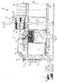
- fig. 2 shows schematically a side view of the spooling machine in fig. 1;
- fig. 3 shows on an enlarged scale the spooling device in fig. 1, in a first operating condition;
- fig. 4 shows on an enlarged scale the spooling device in fig. 1, in a second operating condition;
- fig. 5 shows a view from below of an enlarged detail of the spooling device in fig. 1;
- figs. 6a-6b show three-dimensional respective part views of two possible wound bodies pressed and tied, made using the spooling device according to the present invention;
- figs. 7a-7b-7c show a plane view of some variants of wound bodies made using the spooling device in fig. 1 having containing means with a non-circular section;
- fig. 8 shows a variant of a container of the spooling device in fig. 1 suitable for steaming and dyeing;
- fig. 9 shows a variant of the spooling device according to the present invention.
- With reference to the attached drawings, a spooling
device 10 according to the present invention is installed in a spoolingmachine 11. - To be more exact, the spooling
device 10 substantially comprises afeed unit 12 which picks up theyarn 17 from a spinningspool 13, from one ormore reels 15, or from one or more so-calledwound bodies 16, the latter for example obtained previously with the method anddevice 10 according to the present invention, a super-feed/reserve unit 26 which forms a store for feedingyarn 17, a formingunit 32 in which thewound body 16 is formed, and a doffing, pressing and tyingdevice 51 which picks up thewound body 16 formed in the formingunit 32 and prepares it for packing and subsequent working steps. - The
feed unit 12 comprises, in a substantially known manner, a plurality of devices, respectively to control and limit theballon 19, atensioner device 20, athread feeler 21, aknotter 22, a slub-catcher andmetering device 23, and possibly aparaffining device 25 and/or thread-gripper. The super-feed/reserve unit 26 comprises anaccumulation drum 27, upstream and downstream of which there are two groups of calenders, respectively a pick-upcalender 29 and an unwindingcalender 30, and adeflection calender 31 which introduces the yarn into the formingunit 32. - The super-feed/
reserve unit 26 allows to accumulate a determinate quantity ofyarn 17 in theaccumulation drum 27, so as to define a store ofyarn 17 upstream of the formingunit 32. - This store allows to feed the forming
unit 32 substantially continuously, even when slub-catching operations are carried out, or operations to replace the spinningspool 13, or other operations which normally require the temporary stoppage of the spoolingmachine 11, thus considerably increasing the performance of the spoolingmachine 11. - Hereafter we shall describe, simply as a non-restrictive example, some steps in the functioning of the super-feed/
reserve unit 26, in the case where the slub-catcher device 23 identifies a defect in theyarn 17. - Once a defect is detected, an alarm signal is emitted and the movement of the pick-up
calenders 29 and theaccumulation drum 27 is stopped, while the unwinding calenders 30 continue to feed theyarn 17 to the formingunit 32. - The pick-up
calenders 29 normally detect the length of theyarn 17 that has passed through from the moment of the signal to the stoppage of theyarn 17, and invert the direction of rotation in order to remove from theaccumulation drum 27 the correct quantity ofyarn 17, in which the defect is contained, said length having been memorized during the stoppage. At the same time, two thread-catcher mouths rotate, respectivelyspool head 24 andreel head 28, intercepting theyarn 17 that is stationary in a position suitable for pick-up. - Subsequently, the
yarn 17 is cut in a known manner by the slub-catcher device 23 in correspondence with the defective segment, which segment is sucked up and removed by the mouth that catches thereel head 28 before being joined with the spool head. - At this point the
knotting device 22 makes the knot and the pick-upcalenders 29 restart their normal rotation, increasing the speed in order to reconstitute the store ofyarn 17 in theaccumulation drum 27. - During all these operations, the unwinding calenders 30 have fed the forming
unit 32 substantially continuously. - The forming
unit 32 comprises two feed calenders 33, a thread-guide channel 36 rotating around a second substantially vertical axis "X", and having a substantially S-shaped development, adistributor plate 37 associated with the thread-guide channel 36 by means of aconnection pin 35, and from whose lower periphery the thread-guide channel 36 faces, and acollector plate 39 substantially facing below thedistributor plate 37, and rotating around a first vertical axis "Y", in this case misaligned with respect to the second vertical axis "X". If the containing means does not have a circular section, thecollector plate 39 will have an alternate rectilinear movement and/or with two directions orthogonal to each other, on a horizontal plane, as explained hereafter. - The
collector plate 39 can be disposed in contact, or with a gap of less than the diameter of theyarn 17 being worked, with respect to thedistributor plate 37, so as to exert a slight pressure on theyarn 17 also during the deposition of the first spiral and the formation of the first layer of spirals. - To be more exact, the thread-
guide channel 36 comprises an initial segment coaxial with the second vertical axis "X", a final segment in correspondence with the point where theyarn 17 is distributed, and an inclined intermediate segment which connects the initial segment and the final segment. The entity of the orthogonal projection of the intermediate segment on the plane of thedistributor plate 37 represents the radius of rotation of the point of distribution of theyarn 17 on thecollector plate 39, and also the radius of each spiral of thewound body 16 being formed. The spirals made can have a diameter either greater than or smaller than the radius of thecollector plate 39. - The simultaneous rotation of the structure of the
distributor plate 37 and thecollector plate 39, advantageously in opposite directions, according to the direction of torsion of theyarn 17, and the radius of rotation of the point of distribution, determine the formation of successive layers of spirals ofyarn 17, defining awound body 16 having a substantially cylindricalcentral hole 42. - By doing this the
wound body 16 can have sizes, weight and density much greater than those of knownreels 15. - For example, considering a
yarn 17 with a count equal to about 25/1 tex, and a diameter of theyarn 17 equal to about 0.25 mm, thewound body 16 has the spirals distanced from each other by a pitch equal to about 0.25 mm, that is, the same as the diameter of theyarn 17, whereas due to the effect of the slight pressure exerted by thecollector plate 39 on theyarn 17 during the distribution step, the diameter of theyarn 17 is reduced, thus allowing to have a number of layers 117 ofspirals 116 such as to determine a specific density greater by more than 70+80% with respect to a reel of the same size obtained with the state of the art. - The
distributor plate 37 advantageously has a lower surface with a mirror finish, so as not to interfere on theyarn 17 deposited, it is provided on the upper part with twocalenders 40 to distribute and reduce the tension of theyarn 17, disposed in correspondence with the point of distribution of theyarn 17, and is motorized by means of adrive unit 41 kinematically connected to the thread-guide channel 36. - Advantageously, both the thread-
guide channel 36 and thedrive unit 41 are contained inside aprotective casing 34. - As shown in fig. 5, the distribution calenders 40 receive motion from corresponding
conical rollers 65 which roll on a conicalcircular track 66 associated at the upper part with thedistributor plate 37. - The
conical rollers 65 are coaxial and solid with thecalenders 40, so that a revolution of thecalenders 40 corresponds with every revolution of therollers 65. - As the speed of rotation of the thread-
guide channel 36 increases, theconical rollers 65 tend to move radially due to the centrifugal force, they overcome the resistance of respective return springs 67, opening the gap between the twocalenders 40, and thus allow theyarn 17 to exit due to the centrifugal force. - Vice versa, as the speed of rotation of the thread-
guide channel 36 decreases, the action of thespring 67 closes the gap between the twocalenders 40 again. - In this way, it is possible to avoid high speeds of rotation of the
calenders 40, allowing to reach high speeds for forming thewound body 16, much higher than those used in the state of the art. - The
distributor plate 37 is associated in co-planar manner with a fixedplate 38, also advantageously having the surface in contact with theyarn 17 mirror finished, and having sizes corresponding to those of thecollector plate 39. - The
collector plate 39 advantageously has a high-friction upper surface, for example felted, in order to retain theyarn 17 during the deposition step, and is associated at the lower part with apneumatic piston 43 which allows it to be selectively moved along the first axis "Y" according to the number of layers of spirals 117 of thewound body 16. - The connection between the
pneumatic piston 43 and thecollector plate 39 is made advantageously by means of aconnection plate 45, provided with an attachment system that allows the simultaneous rotation or translation of thecollector plate 39 around the first axis "Y", together with thepneumatic piston 43. In this case, thecollector plate 39 and thepneumatic piston 43 are selectively made to rotate by arelative drive unit 49. - If the
container 46 does not have a circular section, but for example square or rectangular, thecollector plate 39 will have the same section as thecontainer 46, it will act with a slight pressure on theyarn 17, exerted by thepiston 43 during the collection step, and will have a rectilinear movement such that the spirals ofyarn 116 will be deposited with the same pitch or distance from each other, the layer of spirals 117 thus being formed by the alternate movement of the system container 46-collector plate 39. - Always assuming that the
yarn 17 has a diameter of about 0.25 mm and a deposition speed of about 2,000 m/min, and that thespirals 116 ofyarn 17 are desired to be distributed on thecollector plate 39 one next to the other, the collector plate will have to have a rotation around its first axis "Y" of several revs per minute. - The descending movement along the first axis "Y" of the
collector plate 39 occurs inside acontainer 46 having inner surfaces able to allow theyarn 17 to slide during the formation of thewound body 16. - The
container 46 rests on arotary plate 47, coaxial with thecollector plate 39 and able to be made to rotate by thesame drive unit 49, so as to have substantially the same speed of rotation as thecollector plate 39. - Moreover, below the cylindrical container 46 a
conveyor belt 50 is provided, advantageously provided with a supporting plate for thecylindrical container 46, and able to selectively move thecylindrical container 46 at least between an inactive position upstream of the formingunit 32, a position for forming thewound body 16 in correspondence with the formingunit 32, and a position for picking up thewound body 16 downstream of the formingunit 32. - The doffing, pressing and tying
device 51 substantially comprises apressure plate 52, above, moved axially by afirst pressure piston 53, and a supportingplate 55, below, on which thecylindrical container 46 slides when thewound body 16 is completely formed. - The supporting
plate 55 is moved axially against thepressure plate 52 by asecond pressure piston 56. - The
wound body 16 is picked up, in fact, by means of gripping, in this case vertically, effected by the supportingplate 55 and thepressure plate 52, and the subsequent lifting of the two, when compression is terminated, as far as outside thecylindrical container 46. - The doffing, pressing and tying
device 51 also comprises an upper containingplate 57, disposed to cover thecontainer 46 and substantially co-planar with thepressure plate 52, when the latter is in an inactive position, and a tyingdevice 59 disposed above the upper containingplate 57, and able to position a plurality of tyingelements 60 on thewound body 16 so as to temporarily consolidate the layers 117 of spirals ofyarn 17 that form it. - Downstream of the doffing, pressing and tying device 51 a
first discharge belt 61 is provided, disposed substantially at the height of the upper containingplate 57 and able to discharge the tied woundbody 16, and asecond discharge belt 62, disposed below thecylindrical container 46 and able to transport the latter, once freed of thewound body 16, to the inactive position where it waits to be transported by theconveyor belt 50 to the position for forming thewound body 16. - The
device 10 also comprises a command andcontrol unit 69 of the programmable type and able to manage and coordinate the movements and drives of the various components of thefeed unit 12, the super-feed/reserve unit 26, the formingunit 32, and the doffing, pressing and tyingdevice 51, according to desired parameters pre-set and/or pre-settable on each occasion. - The spooling
device 10 according to the present invention functions as follows, in the case of acontainer 46 with a cylindrical section. - At the beginning, the
collector plate 39 is inside thecylindrical container 46, which in turn rests on therotary plate 47. - The
collector plate 39 is taken by thepneumatic piston 43 into contact with the lower surface of thedistributor plate 37. - The
distributor plate 37 is made to rotate at high speed by thedrive unit 41, while thecollector plate 39, thecylindrical container 46 and therotary plate 47 on which thecylindrical container 46 rests are made to rotate at low speed by thedrive unit 49. - The
distributor plate 37 and thecollector plate 39 rotate in reciprocally opposite directions, according to the direction of torsion of theyarn 17. - According to a variant, the
distributor plate 37 and thecollector plate 39 rotate in the same direction. - The
yarn 17 is made to exit from thedistributor plate 37 due to the effect of the rotation of the distribution calenders 40, thus starting to deposit in almostcircular spirals 116 on thecollector plate 39. - The felted surface of the
collector plate 39 retains the first layer of spirals 117 ofyarn 17, with respect to thedistributor plate 37. - The pitch at which the spirals are formed is selectively determined by suitably coordinating the speeds of rotation of the
distributor plate 37 and thecollector plate 39 and the entity of the misalignment between the second vertical axis "X" and the first vertical axis "Y", according to the equation:
where ps is the pitch of the spirals, Vr1 and Vr2 are the respective speeds of rotation of the two plates and do is the interaxis between the axis "X" and the axis "Y". - At the end of a complete rotation of the collector plate 39 a complete layer of spirals 117 of
yarn 17 will have formed. - Once the first layer of spirals 117 of
yarn 17 has formed, the subsequent layers will be formed in cooperation between the pressure action of thepneumatic piston 43 and the retaining action that theyarn 17 of the underlying layer exerts on the yarn that is deposited. - At the same time that the spirals of
yarn 17 are progressively formed, thecollector plate 39 is displaced downwards by thepiston 43, in any case exerting a desired pressure on the spirals, in order to confer compactness on thewound body 16. - The pressure exerted by the
collector plate 39 on the layers of spirals being formed can be adjusted, so as to render the operation to form thespirals 116 and the layers 117 sure and accurate. The pressure also cooperates to determine the final density, defining the number of layers 117 ofspirals 116 of which thewound body 16 consists. - At the end of the downward travel of the
collector plate 39, inside thecylindrical container 46 we have awound body 16 having desired shape and density. - If the section of the
container 46 is not circular, but for example square (forming for example thewound body 16 shown in figs. 7b or 7c), thecontainer 46 will have first a rectilinear horizontal movement along the axis "Y", thespirals 116 will be formed by the rotation of thedistributor plate 37 around the axis x and will be deposited on thecollector plate 39 which, acting inside thecontainer 46, will also have a rectilinear movement. The relation between the speed of rotation of thedistributor plate 37 and the speed of translation of thecontainer 46 and thecollector plate 39 will determine the pitch of the spirals. - When a layer of spirals 117 has been formed along one side of the
container 46, the latter will continue its rectilinear movement in a direction orthogonal to the previous one (Y1, Y2, Y3), and on a plane orthogonal to the plane on which the axis x lies, and so on for the other three sides of thesquare container 46, thus obtaining the distribution of the spirals so as to form a layer formed by four sides. The downward movement of thecollector plate 39, commanded by thepiston 43, determines the progressive formation of the layers of spirals 117. In this way awound body 16 will be obtained with a cubiform shape as shown in fig. 7b, with an emptycentral space 42 also having a square section, indispensable for handling the wound body. - At this point the
container 46 with thewound body 16 formed is taken to its pick-up position, so that thewound body 16 is pressed between thepressure plate 52 and the supportingplate 55, removed from thecylindrical container 46 and then tied by the tyingdevice 59. - When tying has been completed, an expeller member, not shown in the drawings, thrusts the
wound body 16 onto thefirst discharge belt 61, to send it to subsequent steps, while thecylindrical container 46 is returned to its inactive position by thesecond discharge belt 62, in order to leave space for anew container 46 with anew wound body 16 which has formed in the meantime. - According to the variant shown in fig. 9, the device is configured so as to distribute simultaneously, and substantially in the same way as described above, two yarns in layers 117 of spirals. The yarns are deposited in spirals, each separately for an arc of 180° so as not to have reciprocal interference when unwinding, for example during double torsion twisting.
- The separate distribution of the yarns occurs with spirals having a diameter "d" smaller than the semi-diameter "D/2" of the
container 46 in which the pack is collected. This allows to form an emptycentral space 42 of circular shape with characteristics of size suitable to allow to feed the pack to the spindle of the double-torsion twister. - At the moment of twisting, the two yarns will always be in the best technological conditions for unwinding, without creating interference between the yarns, with the same tension for the whole duration of the process. In this way, right from the beginning, the causes for the differences in tension of the yarns between top and base, and between start and end of pack are eliminated, in this way reducing the probabilities of breakages during the twisting step.
- The device shown in fig. 9 comprises two
distribution devices device 32 shown in figs. 2-4; components that are equal or equivalent to those already shown with reference to the previous drawings are given the same reference number, followed by the letter "a" for the device on the left in the drawing, and by the letter "b" for the device on the right, and therefore they will not be described further. Eachdistribution device same collector plate 39 located inside acontainer 46 in this case cylindrical. - The
cylindrical container 46 will be equipped with an alternate movement of rotation of 180° around the axis Y; in this way, eachdistribution unit collector plate 39 layers of spirals 117 obtaining a pack in which the two distinct yarns are available for the subsequent passage in a double-torsion twister in a substantially doubled condition, without any reciprocal interference in the unwinding step. - It is clear however that modifications and/or additions of parts or steps may be made to the spooling method and the spooling
device 10 as described heretofore, without departing from the field and scope of the present invention. - For example, it comes within the field of the present invention to provide that, if the
yarn 17 that forms thewound body 16 is used directly in subsequent working steps, theyarn 17 can be wound inside acylindrical container 46 provided with a shaft having a diameter a little smaller than the diameter of thecentral hole 42. - It also comes within the field of the present invention to provide that instead of the pneumatic piston 43 a pre-loaded helical spring can be provided, or other member able to thrust the collector plate axially upwards during the steps of forming the
wound body 16. The pre-loaded spring is gradually compressed as thecylindrical container 46 fills with the layers of spirals ofyarn 17. - According to another variant, the spooling
device 10 is modular and can be used with othersimilar spooling devices 10 in thesame spooling machine 11. - According to another variant, downstream of the
first discharge belt 61, in the zone where thewound bodies 16 are discharged, as an alternative to the pressing and tying step, an automatic device is provided in order to associate a disk 71 (fig. 8), as a cover, with the cylindrical container which contains thewound body 16, so as to keep the spirals and theyarn 17 controlled and protected during the handling operations. This solution is particularly indicated if the yarn is used in alternate retraction cycles (High Bulk yarns) or dyeing in hanks. The disk can be removed easily when thewound body 16 is used. - According to the variants shown in figs. 7a to 7c, the distribution of the spirals of
yarn 17 can be effected according to a plurality of different geometries. To be more exact, in fig. 7a we have thecollector plate 39 with an alternate rectilinear motion with respect to thedistributor plate 37, thus forming awound body 16 of a substantially rectilinear shape, while in figs. 7a and 7b, we have thecollector plate 39 having a quadrangular rectilinear motion with respect to thedistributor plate 37, thus forming awound body 16 with a substantially cubiform shape. - Naturally, the containers on which the spirals and layers are deposited in order to obtain the
wound body 16 in the alternative solutions shown in figs. 7a-7c must be of the appropriate geometry and size, and also the pressing and tying must follow the most suitable methods for the new forms ofwound body 16. - According to the variant shown in fig. 8, the
cylindrical container 46 has on an outer surface a plurality of throughholes 70. in this solution, thecollector plate 36 and the possibleprotective disk 71 are also provided with said throughholes 70, so as to allow, in subsequent steps, an easier circulation of the steam or dyebath. - By suitably combining the rotational and rectilinear movement of the
collector plate 39 it is possible to optimize the pack of theyarn 17 inwound bodies 16 according to the use that must then be made of theyarn 17.
Claims (21)
- Method for spooling yarns comprising at least a first unwinding step in which the yarn (17) is unwound from a support member (13, 15, 16), and a second spooling step, in which said yarn (17) is disposed in layers according to a desired order, characterized in that, in said second spooling step, said yarn (17) is disposed inside a containing means (46) in overlapping layers, in which each of said layers (117) consists of a plurality of contiguous spirals (116) of yarn (17) and distributed according to the geometry of said containing means (46), wherein said spirals (116) are formed by deposition means (35, 36, 37) able to rotate around a second forming axis (X) of said spirals (116), and wherein said spirals (116) are deposited on collection means (39) able to rotate and/or move linearly around/with respect to a relative first forming axis (Y; Y, Y1, Y2, Y3) of said layers (117), wherein said second forming axis (X) of said spirals (116) does not coincide with said forming axis (Y; Y, Y1, Y2, Y3) of said layers (117).
- Method as in claim 1, wherein said containing means (46) has a circular section, characterized in that said contiguous spirals (116) of yarn (17) are disposed around said first axis of rotation (Y), which is longitudinal and median with respect to said containing means (46) and is parallel and misaligned with respect to said second forming axis (X) of said spirals.
- Method as in claim 1, wherein said containing means (46) has a square or rectangular section, characterized in that said contiguous spirals (116) of yarn (17) are disposed along axes of translation (Y, Y1, Y2, Y3) orthogonal to each other and lying on a plane orthogonal to said forming axis (X) of said spirals (116).
- Method as in claim 1, characterized in that, before the step of depositing the spirals (116) in the containing means (46), it provides a step of releasing the unwinding tension of the yarn (17) performed by calender means (40).
- Method as in claim 1, characterized in that between said first unwinding step and said second spooling step at least an accumulation step is provided in which an accumulation store of said yarn (17) is created, so as to allow the substantially continuous deposition of said yarn (17) in said containing means (46).
- Method as in any claim hereinbefore, characterized in that downstream of said second spooling step at least a pressing step is provided in which said layers consisting of contiguous spirals of said yarn (17) are pressed one against the other and discharged from said containing means (46).
- Method as in claim 6, characterized in that downstream of said pressing step a tying step is provided in which said layers are tied to each other for packing.
- Device for spooling yarns comprising at least a feed unit (12) able to unwind the yarn (17) from a support member (13, 15, 16), and a forming unit (32) able to deposit said yarn (17) in layers, characterized in that said forming unit (32) comprises at least a containing means (46) in which said yarn (17) is able to be deposited in overlapping layers on a collection plate (39) movable with a rotational or linear motion according to a first axis (Y; Y, Y1, Y2, Y3), and deposition means (35, 36, 37) cooperating with said containing means (46) and able to form a plurality of contiguous spirals (116) of yarn (17) and distributed according to the geometry of said containing means (46), in order to form each of said layers (117), said deposition means (35, 36, 37) being able to rotate around a second forming axis (X) of said spirals (116), not coinciding with said first forming axis (Y; Y, Y1, Y2, Y3) of said layers (117).
- Device as in claim 8, wherein said containing means (46) has a circular section, characterized in that said first axis (Y) for forming layers (117) is parallel and misaligned with respect to said second axis (X) for forming spirals (116).
- Device as in claim 8, wherein said containing means (46) has a square or rectangular section, characterized in that said axes (Y; Y, Y1, Y2, Y3) for forming layers (117) lie on a plane substantially orthogonal to the plane on which the second axis (X) for forming spirals (116) lies.
- Device as in claim 9, characterized in that said deposition means (35, 36, 37) and said collector plate (39) rotate in reciprocally opposite directions, according to the direction of torsion of the yarn (17).
- Device as in any claim from 8 to 11, characterized in that said deposition means comprises at least a thread-guide channel (36) able to rotate around said second forming axis (X) of said spirals, and having a substantially S-shaped development, said thread-guide channel (36) having an inlet coaxial with said second forming axis of said spirals (116) and an outlet, laterally displaced with respect to said inlet, of a value equal to the radius of forming of said spirals (116), and a distributor plate (37) associated with said thread-guide channel (36) and disposed with a lower specular surface in contact with said spirals (116).
- Device as in claim 10, characterized in that calender means (40) are associated with said distributor plate (37), able to modify the speed of deposition of said yarn (17) according to the speed of rotation of said deposition means (35, 36, 37) in order to reduce the deposition tension thereof.
- Device as in any claim from 8 to 13, characterized in that said collector plate (39) has an upper surface with a high friction coefficient in order to retain said yarn (17) during its deposition, and an actuator member (43) associated at the lower part with said collector plate (39) and able to move said collector plate (39) linearly inside said containing means (46) during the forming of said layers.
- Device as in any claim from 8 to 13, characterized in that it also comprises a auper-feed/reserve unit (26), disposed upstream of said forming unit (32) and comprising an accumulation drum (27) able to define a feed store of said yarn (17), so as to feed substantially continuously, by means of unwinding means (30), said deposition means (35, 36, 37) even in the event of an interruption to said feed unit (12), and allow to unwind said yarn (17) from said support member (13, 15, 16), by means of pick-up means (29), even during the possible replacement of said containing means (46).
- Device as in claim 15, characterized in that said pick-up means comprises at least a group of removal and measuring calenders (29) able to remove from said accumulation drum (27) a segment of said yarn (17) found defective by slub-catcher means (23).
- Device as in any claim from 8 to 16, characterized in that it also comprises a doffing, pressing and tying device (51) disposed downstream of said forming unit (32) and comprising pressure members (52, 55) able to axially grip with pressure the layers of spirals of yarn formed in said forming unit (32) and to take them outside said containing means (46), and packing means (56) able to at least temporarily consolidate the reciprocal positioning of said layers (117).
- Device as in any claim from 8 to 17, characterized in that it also comprises a programmable command and control unit (69) able to manage and coordinate the movements and drives of the various components of the spooling device (10).
- Device as in any claim hereinbefore, characterized in that it comprises two distribution devices (32a, 32b) disposed substantially specular with respect to each other, each fed by its own yarn, and able to distribute the relative yarn on the same collection plate (39) located inside the same container (46).
- Wound body, characterized in that it consists of at least a yarn (17) disposed inside a containing means (46) in overlapping layers, wherein each of said layers consists of a plurality of contiguous spirals of yarn (17) distributed according to the geometry of said containing means (46) and tied with tying segments (60) able to at least temporarily consolidate the reciprocal positioning of said layers.
- Wound body obtainable using a method as in any claim from 1 to 7.
Applications Claiming Priority (1)
| Application Number | Priority Date | Filing Date | Title |
|---|---|---|---|
| IT000142A ITUD20050142A1 (en) | 2005-09-14 | 2005-09-14 | METHOD AND ROLLING DEVICE OF A YARN AND BODY WRAPPED SO THAT IS REALIZED |
Publications (3)
| Publication Number | Publication Date |
|---|---|
| EP1764333A2 true EP1764333A2 (en) | 2007-03-21 |
| EP1764333A3 EP1764333A3 (en) | 2007-09-19 |
| EP1764333B1 EP1764333B1 (en) | 2011-03-09 |
Family
ID=40222877
Family Applications (1)
| Application Number | Title | Priority Date | Filing Date |
|---|---|---|---|
| EP06120412A Active EP1764333B1 (en) | 2005-09-14 | 2006-09-11 | Method and device for spooling a yarn and wound body thus achieved |
Country Status (4)
| Country | Link |
|---|---|
| EP (1) | EP1764333B1 (en) |
| AT (1) | ATE501076T1 (en) |
| DE (1) | DE602006020528D1 (en) |
| IT (1) | ITUD20050142A1 (en) |
Cited By (8)
| Publication number | Priority date | Publication date | Assignee | Title |
|---|---|---|---|---|
| WO2009132467A3 (en) * | 2008-04-28 | 2010-03-25 | Maschinenfabrik Rieter Ag | Device and method for filling cans |
| EP2216432A1 (en) | 2009-02-04 | 2010-08-11 | Murata Machinery, Ltd. | Yarn processing method and spinning machine |
| EP2484618A4 (en) * | 2009-09-30 | 2013-06-26 | Murata Machinery Ltd | Yarn winder |
| EP2484620A4 (en) * | 2009-09-30 | 2013-06-26 | Murata Machinery Ltd | WIRE BOBINER |
| EP2484619A4 (en) * | 2009-09-30 | 2013-06-26 | Murata Machinery Ltd | Yarn winder |
| EP2774883A1 (en) * | 2013-03-08 | 2014-09-10 | Gebrüder Loepfe AG | Method for winding and cleaning a yarn |
| WO2015180814A1 (en) * | 2014-05-26 | 2015-12-03 | TRüTZSCHLER GMBH & CO. KG | Device on a carder for filling a round can with sliver, e.g. cotton, man-made fibers or the like |
| JP2024019718A (en) * | 2019-03-26 | 2024-02-09 | リンカーン グローバル,インコーポレイテッド | Method and apparatus for packaging wire into storage containers |
Citations (2)
| Publication number | Priority date | Publication date | Assignee | Title |
|---|---|---|---|---|
| US3316609A (en) | 1964-04-16 | 1967-05-02 | Bancroft & Sons Co J | Apparatus for producing a yarn package |
| GB1495578A (en) | 1974-03-22 | 1977-12-21 | Rhone Poulenc Textile | Textile package and process for preparing it |
Family Cites Families (11)
| Publication number | Priority date | Publication date | Assignee | Title |
|---|---|---|---|---|
| DE851010C (en) * | 1948-10-02 | 1952-09-29 | Deutscher Spinnereimaschb Ingo | Method and line for treating fiber ribbons |
| GB880175A (en) * | 1959-06-23 | 1961-10-18 | British Nylon Spinners Ltd | Improvements in or relating to apparatus for coiling yarns and other fibrous structures |
| BE630466A (en) * | 1962-04-11 | 1900-01-01 | ||
| US3478399A (en) * | 1967-06-29 | 1969-11-18 | Turbo Machine Co | Apparatus for coiling a textile product |
| DE2918995A1 (en) * | 1979-05-11 | 1980-11-20 | Schlafhorst & Co W | METHOD AND DEVICE FOR DEPOSING RIBBON IN A CONTAINER |
| FR2540476B1 (en) * | 1983-02-03 | 1985-11-22 | Schlumberger Cie N | POT OF RECEPTION OF TEXTILE MATERIAL IN TAPE INTENDED TO BE THEN COMPRESSED AND LIGATED, AND PRESS EQUIPPED WITH SUCH POTS |
| DE3629735A1 (en) * | 1986-09-01 | 1988-03-03 | Gregor Gebald | METHOD FOR CONNECTING THE START OF THREAD FROM A STOCK REEL TO THE END OF A RUNNING THREAD |
| IT1213859B (en) * | 1987-12-11 | 1990-01-05 | Gualchierani System | AUTOMATIC PLANT FOR THE FORMATION, PRESSING AND HANDLING OF PACKINGS IN TAPE SPIRITS OR TEXTILE WOVES, OR SIMILAR |
| CZ282879B6 (en) * | 1994-06-02 | 1997-11-12 | Vúts Liberec, A. S. | A method and apparatus for storing a strand of textile fibers in a flat strand can |
| US5774941A (en) * | 1997-07-10 | 1998-07-07 | China Textile Institute | Two-head one-cubican drawing system |
| ITUD20020242A1 (en) * | 2002-11-19 | 2004-05-20 | Sergio Zamattio | PREPARATION PROCEDURE FOR SUPPORTS FOR MIXED YARNS, RELATED DEVICE AND SUPPORT OBTAINED WITH SUCH PROCEDURE AND DEVICE |
-
2005
- 2005-09-14 IT IT000142A patent/ITUD20050142A1/en unknown
-
2006
- 2006-09-11 AT AT06120412T patent/ATE501076T1/en not_active IP Right Cessation
- 2006-09-11 DE DE602006020528T patent/DE602006020528D1/en active Active
- 2006-09-11 EP EP06120412A patent/EP1764333B1/en active Active
Patent Citations (2)
| Publication number | Priority date | Publication date | Assignee | Title |
|---|---|---|---|---|
| US3316609A (en) | 1964-04-16 | 1967-05-02 | Bancroft & Sons Co J | Apparatus for producing a yarn package |
| GB1495578A (en) | 1974-03-22 | 1977-12-21 | Rhone Poulenc Textile | Textile package and process for preparing it |
Cited By (10)
| Publication number | Priority date | Publication date | Assignee | Title |
|---|---|---|---|---|
| WO2009132467A3 (en) * | 2008-04-28 | 2010-03-25 | Maschinenfabrik Rieter Ag | Device and method for filling cans |
| CN102015502B (en) * | 2008-04-28 | 2013-01-02 | 里特机械公司 | Device and method for filling cans |
| EP2216432A1 (en) | 2009-02-04 | 2010-08-11 | Murata Machinery, Ltd. | Yarn processing method and spinning machine |
| EP2484618A4 (en) * | 2009-09-30 | 2013-06-26 | Murata Machinery Ltd | Yarn winder |
| EP2484620A4 (en) * | 2009-09-30 | 2013-06-26 | Murata Machinery Ltd | WIRE BOBINER |
| EP2484619A4 (en) * | 2009-09-30 | 2013-06-26 | Murata Machinery Ltd | Yarn winder |
| EP3028977A1 (en) * | 2009-09-30 | 2016-06-08 | Murata Machinery, Ltd. | Yarn winder |
| EP2774883A1 (en) * | 2013-03-08 | 2014-09-10 | Gebrüder Loepfe AG | Method for winding and cleaning a yarn |
| WO2015180814A1 (en) * | 2014-05-26 | 2015-12-03 | TRüTZSCHLER GMBH & CO. KG | Device on a carder for filling a round can with sliver, e.g. cotton, man-made fibers or the like |
| JP2024019718A (en) * | 2019-03-26 | 2024-02-09 | リンカーン グローバル,インコーポレイテッド | Method and apparatus for packaging wire into storage containers |
Also Published As
| Publication number | Publication date |
|---|---|
| ITUD20050142A1 (en) | 2007-03-15 |
| EP1764333A3 (en) | 2007-09-19 |
| DE602006020528D1 (en) | 2011-04-21 |
| EP1764333B1 (en) | 2011-03-09 |
| ATE501076T1 (en) | 2011-03-15 |
Similar Documents
| Publication | Publication Date | Title |
|---|---|---|
| US4340187A (en) | Bobbin changing apparatus | |
| US3913852A (en) | Winding apparatus and process | |
| CN110869302A (en) | Winder | |
| Gandhi | Yarn preparation for weaving: winding | |
| CN101780902B (en) | Yarn winding apparatus and method, take-up winding apparatus and method, and taper end package | |
| US3902644A (en) | Apparatus for the treatment of yarn | |
| JPH04263632A (en) | Traverse motion having yarn guiding element rotatable on two conversional inclined surfaces | |
| EP1764333B1 (en) | Method and device for spooling a yarn and wound body thus achieved | |
| JP6738184B2 (en) | Method and system for operating a complex system consisting of at least one ring spinning machine and at least one winder | |
| CN102249120B (en) | Method for manufacturing spinning cops | |
| CN102574655B (en) | Yarn winder | |
| CN103373639B (en) | Method for preparing cross-wound bobbin and station for implementing method | |
| US4928475A (en) | Fixed length winding method in a two-for-one twister | |
| US5653395A (en) | Yarn winding method and apparatus and package formed thereby | |
| EP2801544A1 (en) | Method and device for operating a workstation of a textile machine for creating cross-wound spools | |
| US3559902A (en) | Continuous winding of yarns | |
| JP7346200B2 (en) | Method and apparatus for detecting yarn loops in a working unit of a textile machine producing wound packages | |
| KR101311097B1 (en) | Method of manufacturing a winding with separate threads | |
| CN100384709C (en) | Method of making cross-wound bobbins | |
| US4561602A (en) | Method and apparatus for facilitating doffing of a yarn processing machine | |
| JPS61127574A (en) | Method and device for simultaneously charging plurality of fiber strand continuously delivered | |
| US1700425A (en) | Automatic winding machine | |
| US5810270A (en) | Method and device for continuous loss free bobbin change | |
| US5205118A (en) | Process and an arrangement for exchanging spools and packages at an individual spinning unit of a spinning machine | |
| JP2019214476A (en) | Method and device of affecting winding condition of ring spinning cop |
Legal Events
| Date | Code | Title | Description |
|---|---|---|---|
| PUAI | Public reference made under article 153(3) epc to a published international application that has entered the european phase |
Free format text: ORIGINAL CODE: 0009012 |
|
| AK | Designated contracting states |
Kind code of ref document: A2 Designated state(s): AT BE BG CH CY CZ DE DK EE ES FI FR GB GR HU IE IS IT LI LT LU LV MC NL PL PT RO SE SI SK TR |
|
| AX | Request for extension of the european patent |
Extension state: AL BA HR MK YU |
|
| PUAL | Search report despatched |
Free format text: ORIGINAL CODE: 0009013 |
|
| AK | Designated contracting states |
Kind code of ref document: A3 Designated state(s): AT BE BG CH CY CZ DE DK EE ES FI FR GB GR HU IE IS IT LI LT LU LV MC NL PL PT RO SE SI SK TR |
|
| AX | Request for extension of the european patent |
Extension state: AL BA HR MK YU |
|
| 17P | Request for examination filed |
Effective date: 20080317 |
|
| AKX | Designation fees paid |
Designated state(s): AT BE BG CH CY CZ DE DK EE ES FI FR GB GR HU IE IS IT LI LT LU LV MC NL PL PT RO SE SI SK TR |
|
| 17Q | First examination report despatched |
Effective date: 20091110 |
|
| GRAP | Despatch of communication of intention to grant a patent |
Free format text: ORIGINAL CODE: EPIDOSNIGR1 |
|
| GRAS | Grant fee paid |
Free format text: ORIGINAL CODE: EPIDOSNIGR3 |
|
| GRAA | (expected) grant |
Free format text: ORIGINAL CODE: 0009210 |
|
| AK | Designated contracting states |
Kind code of ref document: B1 Designated state(s): AT BE BG CH CY CZ DE DK EE ES FI FR GB GR HU IE IS IT LI LT LU LV MC NL PL PT RO SE SI SK TR |
|
| REG | Reference to a national code |
Ref country code: GB Ref legal event code: FG4D |
|
| REG | Reference to a national code |
Ref country code: CH Ref legal event code: EP |
|
| REG | Reference to a national code |
Ref country code: IE Ref legal event code: FG4D |
|
| REF | Corresponds to: |
Ref document number: 602006020528 Country of ref document: DE Date of ref document: 20110421 Kind code of ref document: P |
|
| REG | Reference to a national code |
Ref country code: DE Ref legal event code: R096 Ref document number: 602006020528 Country of ref document: DE Effective date: 20110421 |
|
| REG | Reference to a national code |
Ref country code: NL Ref legal event code: VDEP Effective date: 20110309 |
|
| PG25 | Lapsed in a contracting state [announced via postgrant information from national office to epo] |
Ref country code: SE Free format text: LAPSE BECAUSE OF FAILURE TO SUBMIT A TRANSLATION OF THE DESCRIPTION OR TO PAY THE FEE WITHIN THE PRESCRIBED TIME-LIMIT Effective date: 20110309 Ref country code: GR Free format text: LAPSE BECAUSE OF FAILURE TO SUBMIT A TRANSLATION OF THE DESCRIPTION OR TO PAY THE FEE WITHIN THE PRESCRIBED TIME-LIMIT Effective date: 20110610 Ref country code: LT Free format text: LAPSE BECAUSE OF FAILURE TO SUBMIT A TRANSLATION OF THE DESCRIPTION OR TO PAY THE FEE WITHIN THE PRESCRIBED TIME-LIMIT Effective date: 20110309 Ref country code: ES Free format text: LAPSE BECAUSE OF FAILURE TO SUBMIT A TRANSLATION OF THE DESCRIPTION OR TO PAY THE FEE WITHIN THE PRESCRIBED TIME-LIMIT Effective date: 20110620 Ref country code: LV Free format text: LAPSE BECAUSE OF FAILURE TO SUBMIT A TRANSLATION OF THE DESCRIPTION OR TO PAY THE FEE WITHIN THE PRESCRIBED TIME-LIMIT Effective date: 20110309 |
|
| LTIE | Lt: invalidation of european patent or patent extension |
Effective date: 20110309 |
|
| PG25 | Lapsed in a contracting state [announced via postgrant information from national office to epo] |
Ref country code: CY Free format text: LAPSE BECAUSE OF FAILURE TO SUBMIT A TRANSLATION OF THE DESCRIPTION OR TO PAY THE FEE WITHIN THE PRESCRIBED TIME-LIMIT Effective date: 20110309 Ref country code: FI Free format text: LAPSE BECAUSE OF FAILURE TO SUBMIT A TRANSLATION OF THE DESCRIPTION OR TO PAY THE FEE WITHIN THE PRESCRIBED TIME-LIMIT Effective date: 20110309 Ref country code: NL Free format text: LAPSE BECAUSE OF FAILURE TO SUBMIT A TRANSLATION OF THE DESCRIPTION OR TO PAY THE FEE WITHIN THE PRESCRIBED TIME-LIMIT Effective date: 20110309 Ref country code: SI Free format text: LAPSE BECAUSE OF FAILURE TO SUBMIT A TRANSLATION OF THE DESCRIPTION OR TO PAY THE FEE WITHIN THE PRESCRIBED TIME-LIMIT Effective date: 20110309 Ref country code: BG Free format text: LAPSE BECAUSE OF FAILURE TO SUBMIT A TRANSLATION OF THE DESCRIPTION OR TO PAY THE FEE WITHIN THE PRESCRIBED TIME-LIMIT Effective date: 20110609 Ref country code: AT Free format text: LAPSE BECAUSE OF FAILURE TO SUBMIT A TRANSLATION OF THE DESCRIPTION OR TO PAY THE FEE WITHIN THE PRESCRIBED TIME-LIMIT Effective date: 20110309 |
|
| PG25 | Lapsed in a contracting state [announced via postgrant information from national office to epo] |
Ref country code: BE Free format text: LAPSE BECAUSE OF FAILURE TO SUBMIT A TRANSLATION OF THE DESCRIPTION OR TO PAY THE FEE WITHIN THE PRESCRIBED TIME-LIMIT Effective date: 20110309 |
|
| PG25 | Lapsed in a contracting state [announced via postgrant information from national office to epo] |
Ref country code: EE Free format text: LAPSE BECAUSE OF FAILURE TO SUBMIT A TRANSLATION OF THE DESCRIPTION OR TO PAY THE FEE WITHIN THE PRESCRIBED TIME-LIMIT Effective date: 20110309 Ref country code: PT Free format text: LAPSE BECAUSE OF FAILURE TO SUBMIT A TRANSLATION OF THE DESCRIPTION OR TO PAY THE FEE WITHIN THE PRESCRIBED TIME-LIMIT Effective date: 20110711 |
|
| PGFP | Annual fee paid to national office [announced via postgrant information from national office to epo] |
Ref country code: CH Payment date: 20110923 Year of fee payment: 6 |
|
| PG25 | Lapsed in a contracting state [announced via postgrant information from national office to epo] |
Ref country code: SK Free format text: LAPSE BECAUSE OF FAILURE TO SUBMIT A TRANSLATION OF THE DESCRIPTION OR TO PAY THE FEE WITHIN THE PRESCRIBED TIME-LIMIT Effective date: 20110309 Ref country code: CZ Free format text: LAPSE BECAUSE OF FAILURE TO SUBMIT A TRANSLATION OF THE DESCRIPTION OR TO PAY THE FEE WITHIN THE PRESCRIBED TIME-LIMIT Effective date: 20110309 Ref country code: IS Free format text: LAPSE BECAUSE OF FAILURE TO SUBMIT A TRANSLATION OF THE DESCRIPTION OR TO PAY THE FEE WITHIN THE PRESCRIBED TIME-LIMIT Effective date: 20110709 Ref country code: RO Free format text: LAPSE BECAUSE OF FAILURE TO SUBMIT A TRANSLATION OF THE DESCRIPTION OR TO PAY THE FEE WITHIN THE PRESCRIBED TIME-LIMIT Effective date: 20110309 |
|
| PGFP | Annual fee paid to national office [announced via postgrant information from national office to epo] |
Ref country code: DE Payment date: 20110923 Year of fee payment: 6 Ref country code: FR Payment date: 20110928 Year of fee payment: 6 |
|
| PLBE | No opposition filed within time limit |
Free format text: ORIGINAL CODE: 0009261 |
|
| STAA | Information on the status of an ep patent application or granted ep patent |
Free format text: STATUS: NO OPPOSITION FILED WITHIN TIME LIMIT |
|
| 26N | No opposition filed |
Effective date: 20111212 |
|
| PG25 | Lapsed in a contracting state [announced via postgrant information from national office to epo] |
Ref country code: PL Free format text: LAPSE BECAUSE OF FAILURE TO SUBMIT A TRANSLATION OF THE DESCRIPTION OR TO PAY THE FEE WITHIN THE PRESCRIBED TIME-LIMIT Effective date: 20110309 Ref country code: DK Free format text: LAPSE BECAUSE OF FAILURE TO SUBMIT A TRANSLATION OF THE DESCRIPTION OR TO PAY THE FEE WITHIN THE PRESCRIBED TIME-LIMIT Effective date: 20110309 |
|
| REG | Reference to a national code |
Ref country code: DE Ref legal event code: R097 Ref document number: 602006020528 Country of ref document: DE Effective date: 20111212 |
|
| PG25 | Lapsed in a contracting state [announced via postgrant information from national office to epo] |
Ref country code: MC Free format text: LAPSE BECAUSE OF NON-PAYMENT OF DUE FEES Effective date: 20110930 |
|
| GBPC | Gb: european patent ceased through non-payment of renewal fee |
Effective date: 20110911 |
|
| REG | Reference to a national code |
Ref country code: IE Ref legal event code: MM4A |
|
| PG25 | Lapsed in a contracting state [announced via postgrant information from national office to epo] |
Ref country code: IE Free format text: LAPSE BECAUSE OF NON-PAYMENT OF DUE FEES Effective date: 20110911 |
|
| PG25 | Lapsed in a contracting state [announced via postgrant information from national office to epo] |
Ref country code: GB Free format text: LAPSE BECAUSE OF NON-PAYMENT OF DUE FEES Effective date: 20110911 |
|
| REG | Reference to a national code |
Ref country code: CH Ref legal event code: PL |
|
| PG25 | Lapsed in a contracting state [announced via postgrant information from national office to epo] |
Ref country code: LU Free format text: LAPSE BECAUSE OF NON-PAYMENT OF DUE FEES Effective date: 20110911 |
|
| REG | Reference to a national code |
Ref country code: FR Ref legal event code: ST Effective date: 20130531 |
|
| PG25 | Lapsed in a contracting state [announced via postgrant information from national office to epo] |
Ref country code: DE Free format text: LAPSE BECAUSE OF NON-PAYMENT OF DUE FEES Effective date: 20130403 Ref country code: LI Free format text: LAPSE BECAUSE OF NON-PAYMENT OF DUE FEES Effective date: 20120930 Ref country code: CH Free format text: LAPSE BECAUSE OF NON-PAYMENT OF DUE FEES Effective date: 20120930 |
|
| PG25 | Lapsed in a contracting state [announced via postgrant information from national office to epo] |
Ref country code: FR Free format text: LAPSE BECAUSE OF NON-PAYMENT OF DUE FEES Effective date: 20121001 |
|
| REG | Reference to a national code |
Ref country code: DE Ref legal event code: R119 Ref document number: 602006020528 Country of ref document: DE Effective date: 20130403 |
|
| PG25 | Lapsed in a contracting state [announced via postgrant information from national office to epo] |
Ref country code: TR Free format text: LAPSE BECAUSE OF FAILURE TO SUBMIT A TRANSLATION OF THE DESCRIPTION OR TO PAY THE FEE WITHIN THE PRESCRIBED TIME-LIMIT Effective date: 20110309 |
|
| PG25 | Lapsed in a contracting state [announced via postgrant information from national office to epo] |
Ref country code: HU Free format text: LAPSE BECAUSE OF FAILURE TO SUBMIT A TRANSLATION OF THE DESCRIPTION OR TO PAY THE FEE WITHIN THE PRESCRIBED TIME-LIMIT Effective date: 20110309 |
|
| PGFP | Annual fee paid to national office [announced via postgrant information from national office to epo] |
Ref country code: IT Payment date: 20240925 Year of fee payment: 19 |