EP1764324B1 - Sheet conveying apparatus - Google Patents
Sheet conveying apparatus Download PDFInfo
- Publication number
- EP1764324B1 EP1764324B1 EP06018650A EP06018650A EP1764324B1 EP 1764324 B1 EP1764324 B1 EP 1764324B1 EP 06018650 A EP06018650 A EP 06018650A EP 06018650 A EP06018650 A EP 06018650A EP 1764324 B1 EP1764324 B1 EP 1764324B1
- Authority
- EP
- European Patent Office
- Prior art keywords
- sheet
- rollers
- pair
- conveying
- width direction
- Prior art date
- Legal status (The legal status is an assumption and is not a legal conclusion. Google has not performed a legal analysis and makes no representation as to the accuracy of the status listed.)
- Expired - Fee Related
Links
Images


Classifications
-
- B—PERFORMING OPERATIONS; TRANSPORTING
- B65—CONVEYING; PACKING; STORING; HANDLING THIN OR FILAMENTARY MATERIAL
- B65H—HANDLING THIN OR FILAMENTARY MATERIAL, e.g. SHEETS, WEBS, CABLES
- B65H29/00—Delivering or advancing articles from machines; Advancing articles to or into piles
- B65H29/12—Delivering or advancing articles from machines; Advancing articles to or into piles by means of the nip between two, or between two sets of, moving tapes or bands or rollers
-
- G—PHYSICS
- G03—PHOTOGRAPHY; CINEMATOGRAPHY; ANALOGOUS TECHNIQUES USING WAVES OTHER THAN OPTICAL WAVES; ELECTROGRAPHY; HOLOGRAPHY
- G03G—ELECTROGRAPHY; ELECTROPHOTOGRAPHY; MAGNETOGRAPHY
- G03G15/00—Apparatus for electrographic processes using a charge pattern
- G03G15/65—Apparatus which relate to the handling of copy material
- G03G15/6538—Devices for collating sheet copy material, e.g. sorters, control, copies in staples form
- G03G15/6547—Shifting sets of sheets in the discharge tray
-
- B—PERFORMING OPERATIONS; TRANSPORTING
- B65—CONVEYING; PACKING; STORING; HANDLING THIN OR FILAMENTARY MATERIAL
- B65H—HANDLING THIN OR FILAMENTARY MATERIAL, e.g. SHEETS, WEBS, CABLES
- B65H2301/00—Handling processes for sheets or webs
- B65H2301/30—Orientation, displacement, position of the handled material
- B65H2301/36—Positioning; Changing position
- B65H2301/361—Positioning; Changing position during displacement
- B65H2301/3613—Lateral positioning
-
- B—PERFORMING OPERATIONS; TRANSPORTING
- B65—CONVEYING; PACKING; STORING; HANDLING THIN OR FILAMENTARY MATERIAL
- B65H—HANDLING THIN OR FILAMENTARY MATERIAL, e.g. SHEETS, WEBS, CABLES
- B65H2404/00—Parts for transporting or guiding the handled material
- B65H2404/10—Rollers
- B65H2404/14—Roller pairs
- B65H2404/142—Roller pairs arranged on movable frame
- B65H2404/1424—Roller pairs arranged on movable frame moving in parallel to their axis
-
- B—PERFORMING OPERATIONS; TRANSPORTING
- B65—CONVEYING; PACKING; STORING; HANDLING THIN OR FILAMENTARY MATERIAL
- B65H—HANDLING THIN OR FILAMENTARY MATERIAL, e.g. SHEETS, WEBS, CABLES
- B65H2404/00—Parts for transporting or guiding the handled material
- B65H2404/10—Rollers
- B65H2404/16—Details of driving
- B65H2404/161—Means for driving a roller parallely to its axis of rotation, e.g. during its rotation
-
- B—PERFORMING OPERATIONS; TRANSPORTING
- B65—CONVEYING; PACKING; STORING; HANDLING THIN OR FILAMENTARY MATERIAL
- B65H—HANDLING THIN OR FILAMENTARY MATERIAL, e.g. SHEETS, WEBS, CABLES
- B65H2511/00—Dimensions; Position; Numbers; Identification; Occurrences
- B65H2511/20—Location in space
-
- G—PHYSICS
- G03—PHOTOGRAPHY; CINEMATOGRAPHY; ANALOGOUS TECHNIQUES USING WAVES OTHER THAN OPTICAL WAVES; ELECTROGRAPHY; HOLOGRAPHY
- G03G—ELECTROGRAPHY; ELECTROPHOTOGRAPHY; MAGNETOGRAPHY
- G03G2215/00—Apparatus for electrophotographic processes
- G03G2215/00362—Apparatus for electrophotographic processes relating to the copy medium handling
- G03G2215/00367—The feeding path segment where particular handling of the copy medium occurs, segments being adjacent and non-overlapping. Each segment is identified by the most downstream point in the segment, so that for instance the segment labelled "Fixing device" is referring to the path between the "Transfer device" and the "Fixing device"
- G03G2215/00417—Post-fixing device
- G03G2215/00426—Post-treatment device adding qualities to the copy medium product
Definitions
- the present invention relates to a sheet conveying apparatus for conveying a sheet.
- An initial sheet processing apparatus having a sheet sorting function has adopted a mechanism in which the stacking tray is moved stepwise toward the width direction in order to shift stacking positions of the sheets toward the width direction.
- a heavy stacking tray on which as many as several thousand sheets are stacked, in the width direction from a mechanistic perspective and in view of power consumption.
- a process tray is arranged on a front stage of the stacking tray, a sheet or a sheet bundle is moved toward the width direction on the process tray, and then the sheet or the sheet bundle is moved and stacked onto an ascendable/descendable stacking tray.
- the process tray is large in size and constituted of a large number of parts in order to stack the sheets evenly, so the sheet processing apparatus inevitably becomes large in size.
- an arrangement place for the process tray is limited to a place immediately before the stacking tray, so it is necessary to arrange the process tray in each branch destination when a sheet conveying path is diverged into a plurality of conveying paths.
- a mechanism in which a pair of rollers arranged on the sheet conveying path are moved toward the width direction while nipping the sheet to thereby shift a sheet conveying position in the width direction of the sheet.
- JP S61-33459 A discloses a sheet processing apparatus built in an image forming apparatus.
- paired discharge rollers for discharging sheets onto a stacking tray are moved in an axial direction to sort and stack the sheets on the stacking tray.
- the sheets which are obtained after being subjected to image formation and image fixing, and which are then discharged onto the stacking tray are moved in two steps toward the axial direction while being nipped by the paired discharge rollers, thereby being sorted and stacked on the stacking tray by shifting the stacking positions of the sheets in the width direction on the stacking tray.
- the inclination of the sheet which is caused due to a sliding resistance generated between the sheet and a conveying guide is generally called a skew.
- a technique of achieving a position correcting function in the width direction in which a position detecting sensor for detecting a position of a side edge of the sheet is combined with the pair of conveying rollers movable in the width direction, thereby aligning the side edges of the respective sheets, or stacking the sheets by aligning each one side edge of the sheets irrespective of using the sheets having different sizes.
- a position detecting sensor for detecting a position of a side edge of the sheet is combined with the pair of conveying rollers movable in the width direction, thereby aligning the side edges of the respective sheets, or stacking the sheets by aligning each one side edge of the sheets irrespective of using the sheets having different sizes.
- JP-A-05 193788 , JP-A-04 260558 , JP-A-09 329885 , JP-A-2002 338089 , and US-A-6 019365 , JP-A-2004 051256 each relate to recording sheet conveyance devices.
- the present invention has an object to provide a sheet conveying apparatus and a sheet processing apparatus in which a sheet is less likely to be inclined even when a thick sheet is used to be moved in a width direction in a conveying path having a small curvature radius.
- a sheet conveying apparatus includes a first pair of rollers for nipping and conveying a sheet; a second pair of rollers provided downstream of the first pair of rollers in a conveying direction of the sheet,for nipping and conveying the sheet; a position detecting sensor for detecting a position of the sheet in a width direction which is perpendicular to the conveying direction, by moving in the width direction and thereby detecting a side edge of the sheet; a drive mechanism for moving the first and the second pair of rollers in the width direction; and a control device for controlling the drive mechanism to move the first and the second pair of rollers in the width direction, wherein the control device calculates a displacement amount in the width direction of the sheet to be conveyed to the first and the second pair of rollers, and controls the drive mechanism so as to move the first and the second pair of rollers in the width direction by the displacement amount calculated from a preset shift amount in the width direction for sorting each sheet group and a lateral registration error for
- a sheet processing apparatus includes such a sheet conveying apparatus.
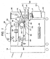
- FIG. 1 is an explanatory view of an image forming apparatus mounted with a sheet processing apparatus according to this embodiment.
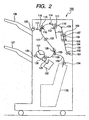
- FIG. 2 is an explanatory view of a structure of the sheet processing apparatus according to this embodiment.
- FIG. 3 is an explanatory view of a structure of a shift unit viewed from a side surface thereof.
- FIG. 4 is a perspective view of the shift unit
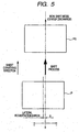
- FIG. 5 is an explanatory view of an operation of the shift unit in a non-shift mode.
- FIG. 6 is an explanatory view of an operation of the shift unit in a case of performing shift by an amount of +Y.
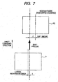
- FIG. 7 is an explanatory view of an operation of the shift unit in a case of performing shift by an amount of -Y.
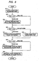
- FIG. 8 is a flowchart of a shift mode operation.
- FIG. 9 is an explanatory view of a drive mechanism of release rollers.
- FIG. 10 is an explanatory view of a start position of a buffer process for a sheet.
- FIG. 11 is an explanatory view of a buffer position of the sheet.
- FIG. 12 is an explanatory view of a position for aligning leading edges of sheets.
- FIG. 13 is an explanatory view of a structure of a sheet processing apparatus according to this embodiment.
- the sheet conveying apparatus 100 which is an embodiment of a sheet conveying apparatus according to the present invention, will be described with reference to the drawings.
- the sheet conveying apparatus according to the present invention is not limited to a subsidiary optional apparatus which is additionally provided to an apparatus main body 300 of an image forming apparatus.
- the sheet conveying apparatus may be obtained as an independent sheet processing apparatus including an independent microcomputer control device, or may be carried out by integrally and non-separably incorporating the sheet conveying apparatus into a housing of a copying machine, a facsimile machine, a monochrome printer, a multifunction machine having the functions thereof, or the like.
- the sheet conveying apparatus may be applied to a sheet conveying apparatus for conveying a sheet in a multifunction machine main body or in a printer, or may be applied to an apparatus for conveying a sheet-like document.
- an image forming system of the image forming apparatus is not limited to an electrostatic photographic process described in this embodiment, but may be replaced with an ink-jet image forming apparatus, a stencil printing apparatus, other printing apparatus, and the like.
- the sheet processing apparatus 100 is not limited to a combination of limitative constitutional members described below, but other different embodiments may be constituted by a variety of combinations using various alternative members including those members.
- FIG. 1 is an explanatory view of an image forming apparatus mounted with a sheet processing apparatus according to this embodiment.
- the sheet processing apparatus 100 according to this embodiment is arranged on a downstream side of the apparatus main body 300 of the image forming apparatus as an optional apparatus controlled by a control device 950 of the apparatus main body 300.
- the apparatus main body (i.e., copying machine main body) 300 includes a platen glass plate 906 serving as a loading base for a document to be read, an automatic document feeder 500 which feeds the document to be read onto the platen glass plate 906, and the sheet processing apparatus 100 which stacks the sheets having images formed thereon and discharged from the apparatus main body 300.
- a sheet feed part 909 includes cassettes 910 and 911 which are detachably mounted to the apparatus main body 300 and contain sheets P subjected to image formation, and a deck 913 arranged in a pedestal 912.
- the sheets P are fed from the cassette 910 or 911, or the deck 913. Meanwhile, light emitted from a light source 907 and reflected by a document D loaded on the document loading base 906 is irradiated on a photosensitive drum 914 through a lens system 908.
- the photosensitive drum 914 is charged by a primary charger 919 in advance, and an electrostatic latent image is formed on the photosensitive drum 914 by being irradiated with light.
- the electrostatic latent image is developed by a developing device 915, thereby obtaining a toner image.
- a skew of the sheet P fed from the sheet feed part 909 is corrected by a registration roller 901, and then the sheet P is conveyed to an image forming part 902 at a predetermined timing.
- the toner image formed on a surface of the photosensitive drum 914 is transferred onto the conveyed sheet P by a transfer charger 916.
- the sheet P onto which the toner image is transferred is charged to a polarity opposite to that of the transfer charger 916 by a detach charger 917, and is detached from the photosensitive drum 914.
- the detached sheet P is conveyed to a fixing device 904 by a conveying apparatus 920, and a transferred image is fixed onto the sheet P by the fixing device 904.
- the sheet P having an image fixed thereon is discharged from the apparatus main body through paired discharge rollers 930, and is fed in the sheet processing apparatus 100.
- FIG. 2 is an explanatory view of a structure of the sheet processing apparatus according to this embodiment.
- the sheet processing apparatus 100 according to this embodiment is controlled by the control device 950 of the image forming apparatus to receive the sheet P from the apparatus main body 300. Then, the sheet processing apparatus 100 moves the shift unit 108 in the width direction while operating during the conveyance of the sheet, thereby performing a shift for sorting of the sheets P and correcting displacement in the side edges of the sheets P.
- the width direction is a direction perpendicular to a sheet conveying direction.
- the width direction is not limited to a direction in which an angle of inclination made by the sheet conveying direction is 90 degree.
- the sheet P discharged from the image forming apparatus main body 300 is discharged to a pair of entrance rollers 102 of the sheet processing apparatus 100.
- a discharging timing of the sheet P is detected at the same time by an entrance sensor 101.
- the side edge position of the sheet P conveyed by the pair of entrance rollers 102 is detected by a side edge position detecting sensor 104 while the sheet P passes a conveying path 103.
- an amount of displacement generated in the width direction with respect to a central position of the sheet processing apparatus 100 is detected.
- the displacement amount in the width direction is herein defined as X (representing the center as 0 and forward direction of the apparatus as +; see FIGS. 5 to 7 ).
- the shift unit 108 moves pairs of shift rollers 105 and 107 for conveying the sheet P, integrally with each other in the sheet width direction, while rotationally driving the pairs of shift rollers 105 and 107.
- the shift unit 108 and the operation thereof will be described later in detail with reference to FIGS. 3 and 4 .
- Conveying rollers 110 and release rollers 111 are capable of being brought into press-contact with and being set apart from each other. In a case where the sheet is large in size, the conveying rollers 110 and the release rollers 111 are set apart from each other prior to movement thereof in the width direction by the shift unit 108. This is because a resistance and a torque which are unnecessary for the sheet P moving in the width direction are not to be caused.
- the sheet P conveyed by the conveying rollers 110 and the release rollers 111 which are brought into press-contact with each other is discharged to a pair of buffer rollers 115, and when the sheet P is discharged onto an upper tray 136, an upper path switching flapper 118 is allowed to face downward in advance by a solenoid or the like (not shown). As a result, the sheet P is guided into an upper path conveying path 117, and then discharged and stacked on the upper tray 136 by an upper discharge roller 120.
- the upper path switching flapper 118 is allowed to face upward in advance, so the sheet P is guided into a bundle conveying path 121, and is then discharged to a pair of bundle conveying rollers 122 from a pair of buffer rollers 115 through the bundle conveying path 121.
- a saddle unit 135 arranged at a lower part of the sheet processing apparatus 100 performs a saddle process (i.e., bookbinding process) in which a sheet bundle is obtained, subjected to saddle stitch, and then subjected to half-fold process.
- the saddle process is a commonly used process, so the description thereof will be omitted herein.
- a saddle path switching flapper 125 is allowed to face leftward in advance by the solenoid or the like (not shown), so the sheet P enters a saddle path 133, and is conveyed to the saddle unit 135 by a pair of saddle entrance rollers 134 to be subjected to the saddle process.
- the saddle switching flapper 125 is allowed to face rightward in advance.
- the sheet P enters a lower path 126 from the pair of bundle conveying rollers 122 to be discharged onto a process tray 138 by a pair of lower discharge rollers 128 and temporarily received on the process tray 138.
- the sheets P discharged onto the process tray 138 are aligned on the process tray 138 after a predetermined number of sheets P are stacked by returning means such as a paddle 131 or a knurling belt 129, and are then subjected to a binding process by a stapler 132.
- a sheet bundle obtained on the process tray 138 is discharged and stacked on the lower tray 137 by a pair of bundle discharge rollers 130.
- FIG. 3 is an explanatory view of a structure of a shift unit viewed from a side surface thereof
- FIG. 4 is a perspective view of the shift unit.
- the pairs of shift rollers 105 and 107 are integrally moved in the width direction, thereby achieving the positioning in real time of the side edge of the sheet P without delaying the conveyance of the sheet P.
- the shift unit 108 moves in a direction indicated by the arrow D such that the entirety of a moving case 201, serving as a moving housing member which axially supports the pairs of shift rollers 105 and shift rollers 107, is guided in slide rails 202 and 203 serving as guide members.
- the slide rails 202 and 203 are fixed to a housing structure of the sheet processing apparatus 100 shown in FIG. 2 .
- the moving case 201 is movably supported by four slide bushes 205a, 205b, 205c, and 205d along the slide rails 202 and 203.
- the moving case 201 is mounted with a drive mechanisms for the pair of shift rollers 105 and pair of shift rollers 107.
- a rotational output of a shift conveying motor 208 serving as a drive source is transferred to a rotating shaft of the pair of shift rollers 105 by a drive belt 209.
- the rotation of the pair of shift rollers 105 are transmitted from a pulley 206, which is fixed to the rotating shaft of the pair of shift rollers 105 on an opposite side of the shift conveying motor 208, to a pulley 207, which is fixed to the rotating shaft of the pair of shift rollers 107, through a drive belt 213.
- the shift conveying motor 208 rotates, the pairs of shift rollers 105 and 107 are integrally rotated, thereby conveying the sheet P in a direction indicated by the arrow C.
- a shift motor 210 which generates a driving force for moving the shift unit 108 along the slide rails 202 and 203 is fixed to the housing structure of the sheet processing apparatus 100 shown in FIG. 2 .
- a rotational output of the shift motor 210 which adopts a step motor circulates a drive belt 211.
- the drive belt 211 is fixed to the moving case 201 by a fixing member 212, so the shift unit 108 moves in a direction indicated by the arrow D in accordance with a forward or reverse rotation of the shift motor 210.
- the side edge position detecting sensor 104 (see FIG. 2 ) arranged at an upstream of the shift unit 108 can move in directions indicated by the arrows E along a guide 216 by a drive mechanism (not shown).
- a paper detecting sensor 106 shown in FIG, 2 which is arranged in the shift unit 108 detects the sheet P
- the side edge position detecting sensor 104 starts moving from a home position at an outward side to an inward side to detect the position of the side edge of the sheet P, and then stops moving.
- the control device 950 shown in FIG. 1 detects the movement of the side edge position detecting sensor 104 to calculate the displacement amount in the width direction.
- the displacement amount in the width direction is offset by moving the shift unit 108 in the width direction, thereby aligning the side edge positions of the sheets P.
- a shift mode a shift process in which a shift amount preset with respect to the sheet P is added with the displacement amount in the width direction is performed.
- a pair of upstream-side conveying guides UG1 and UG2 for guiding the sheet.
- the pair of upstream-side conveying guides UG1 and UG2 have a curved shape.
- a pair of downstream-side conveying guides DG1 and DG2 for guiding the sheet.
- the pair of downstream-side conveying guides DG1 and DG2 have a curved shape.
- the sheet P entering the shift unit 108 is nipped by the pairs of shift rollers 105 and 107 which is driven by the shift conveying motor 208, and is conveyed in the direction indicated by the arrow C.
- the side edge position detecting sensor 104 is moved in the direction indicated by the arrows E to detect a displacement amount X in the width direction of the sheet P.
- the control device 950 shown in FIG. 1 actuates the shift motor 210 by the shift amount obtained by adding the displacement amount X in the width direction with the shift amount necessary for each sheet P, while continuously conveying the sheet P, thereby moving the shift unit 108 in the direction indicated by the arrow D.
- the shift motor 210 is actuated to move the shift unit 108 in the width direction, with the result that the sheet P nipped and conveyed by the pairs of shift rollers 105 and 107 is moved in the width direction.
- the pair of upstream-side conveying guides UG1 and UG2 and the pair of downstream-side conveying guides DG1 and DG2 are fixed to the apparatus main body 300, so the sheet P moved in the width direction by the pairs of shift rollers 105 and 107 moves with respect to the pair of upstream-side conveying guides UG1 and UG2 and the pair of downstream-side conveying guides DG1 and DG2.
- the pairs of shift rollers 105 and 107 are two pairs of rollers, so it is possible to reliably grip the sheet P.
- the pairs of shift rollers 105 and 107 and the sheet P are less likely to slide on each other, and the position of the sheet P is less likely to be shifted from an assumed position.
- the description as to the two pairs of shift rollers is given.
- the number of the pairs of shift rollers is not limited to two, but three or more pairs of shift rollers may be used to obtain the same effect.
- FIG. 5 is an explanatory view of an operation of the shift unit in a non-shift mode.
- FIG. 6 is an explanatory view of an operation of the shift unit in a case of performing shift by an amount of +Y.
- FIG. 7 is an explanatory view of an operation of the shift unit in a case of performing shift by an amount of -Y.
- FIG. 8 is a flowchart of a shift mode operation.
- the sheet processing apparatus 100 according to this embodiment is capable of carrying out three shift modes, that is, a non-shift mode (see FIG. 5 ), a front shift mode (see FIG. 6 ), and a rear shift mode (see FIG. 7 ).
- the sheet P discharged from the image forming apparatus 300 shown in FIG. 1 is conveyed in a state where the sheet P is shifted by the amount X with respect to a central position of the sheet processing apparatus 100 (herein, called a displacement in the width direction).
- the side edge position detecting sensor 104 detects the displacement amount X in the width direction as shown in FIG. 3 , and a movement Z1 of the shift unit 108 is derived from the following formula.
- the shift unit 108 When the shift unit 108 is shifted by the movement Z1, the sheet P is moved toward the center of the sheet processing apparatus 100, thereby being conveyed in a state of a sheet PS shown in FIG. 5 .
- the sheet P discharged from the image forming apparatus 300 shown in FIG. 1 is conveyed in a state where the sheet P is shifted by the amount X with respect to the central position of the sheet processing apparatus 100.
- the side edge position detecting sensor 104 detects the displacement amount X in the width direction as shown in FIG. 3 , and a movement Z2 of the shift unit 108 is derived from the following formula.
- the shift unit 108 When the shift unit 108 is shifted by the movement Z2, the sheet P is moved by the amount Y to the front side from the center of the sheet processing apparatus 100, thereby being conveyed in a state of a sheet PS shown in FIG. 6 .
- the sheet P discharged from the image forming apparatus 300 shown in FIG. 1 is conveyed in a state where the sheet P is shifted by the amount X with respect to the central position of the sheet processing apparatus 100.
- the side edge position detecting sensor 104 detects the displacement amount X in the width direction as shown in FIG. 3 , and a movement Z3 of the shift unit 108 is derived from the following formula.
- the shift unit 108 When the shift unit 108 is shifted by the movement Z3, the sheet P is moved to a position shifted by the amount Y to the rear side from the center of the sheet processing apparatus 100, thereby being conveyed in a state of a sheet PS shown in FIG. 7 .
- the control device 950 shown in FIG. 1 of the image forming apparatus moves the side edge position detecting sensor 104 to detect the displacement amount in the width direction of the sheet P (S10), and then determines a sheet size of the sheet P (S20).
- the control device 950 controls a drive mechanism (see FIG. 9 ; to be described later) to set the release rollers 111 apart from the conveying rollers 110, and controls the drive mechanism to decrease a transfer speed of the sheet P by the pairs of shift rollers 105 and 107 (S30).
- the reason for setting apart the release rollers 111 from the conveying rollers 110 is that the sheet P gets wrinkled when the shift unit 108 is moved in the width direction in a state where the sheet P is nipped in each nip between the release rollers 111 and the conveying rollers 110. Further, the reason for decreasing the transfer speed is that the leading edge of the sheet P needs to be prevented from reaching the nip between the pair of buffer rollers 115 without fault.
- the shift process is completed before the leading edge of the sheet P reaches the nip between the conveying rollers 110 and the release rollers 111. Accordingly, a press-contact state and the transfer speed of the release rollers 111 and the conveying rollers 110 are not changed.
- the control device 950 determines whether or not the sheet processing apparatus 100 carries out the shift mode (S40). When determining that the sheet processing apparatus 100 carries out the shift mode (shift mode in S40), the control device 950 performs a control (S51) to carry out the shift process for an offset amount of the displacement amount in the width direction and a necessary shift amount as described with reference to FIGS. 6 and 7 . When determining that the sheet processing apparatus 100 carries out the non-shift mode (non-shift mode in S40), the control device 950 performs a control to carry out the shift process for the offset amount of the displacement amount in the width direction (S52) as described with reference to FIG. 5 .
- the control device 950 determines the sheet size of the sheet P (S60). When determining that the sheet size of the sheet P is the large size (i.e., large size in S60), the control device 950 performs a control to move back the release rollers 111 to be brought into press-contact with the conveying rollers 110, and to restore the decreased transfer speed to the normal transfer speed (S70).
- control device 950 waits until the trailing edge of the sheet P passes through the shift unit 108, moves back the side edge position detecting sensor 104 to an original standby position, and further moves back the shift unit 108 to the original central position (S80), thereby completing a series of the operation. After that, the control device 950 waits until the subsequent sheet P is conveyed thereto, and returns to the initial sequence to repeat the same operation the required number of times.
- the release rollers 111 are set apart from the conveying rollers 110 prior to the shift process performed by the shift unit 108, so it is possible to set a length of the conveying path which is not nipped by the pair of rollers other than the pairs of shift rollers 105 and 107 to be short in order to shift the sheet P.
- the conveyed sheet P is subjected to the shift process within a long and free conveying path by the shift unit 108 according the set mode such as the shift mode and the non-mode.
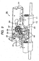
- FIG. 9 is an explanatory view of a drive mechanism of release rollers.
- a drive mechanism 230 for the release rollers 111 a release frame 224 which axially supports the release rollers 111 is caused to ascend/descend with respect to a frame 221 fixed to the sheet processing apparatus 100 shown in FIG. 2 , thereby bringing the release rollers 111 into press-contact with and being set apart from the conveying rollers 110.
- a rotating shaft 220 of the release rollers 111 is rotatably supported with respect to the release frame 224.
- the release frame 224 is guided by shafts 223 fixed to the frame 221, is free to ascend and descend in the direction indicated by the arrow F, and is urged upward by compressive forces of compression springs 222.
- An output gear of a step motor (not shown) for driving and bringing the release rollers 111 into contact with the conveying rollers 110 is engaged with a drive gear 227.
- a rotation of the drive gear 227 is transmitted to a rack gear (not shown) fixed to the release frame 224 through a pinion gear 229 axially fixed to an intermediate gear 226.
- the pinion gear 229 allows the release frame 224 to ascend/descend in accordance with a forward or reverse rotation of the step motor (not shown).
- the drive gear 227 is driven counterclockwise, the drive frame 224 is moved in a release direction (i.e., direction indicated by the arrow F).
- Each release position of the release rollers 111 is a height position where a home position sensor 225, which is fixed to the frame 221, detects a flag of the release frame 224.
- the press-contact state of the release rollers 111 is appropriately controlled by controlling a descending amount of the release frame 224 from the height position detected by the home position sensor 225.
- FIG. 10 is an explanatory view of a start position of a buffer process for a sheet.
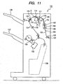
- FIG. 11 is an explanatory view of a buffer position of the sheet.
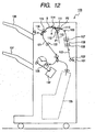
- FIG. 12 is an explanatory view of a position for aligning leading edges of sheets.
- FIGS. 10 to 12 are explanatory views of the buffer process of the sheet P in the sheet processing apparatus 100 shown in FIG. 2 .
- the same reference numerals are given to constituents commonly used in FIG. 2 , and the descriptions thereof will be omitted.
- the sheet processing apparatus 100 has a function in which the sheets P are allowed to stand by in a conveying path provided to an upstream of the stapler 132 or the saddle unit 135 while a plurality of sheets P are stacked, that is, a so-called buffer process function of the sheet P.
- a so-called buffer process function of the sheet P it is possible to perform sheet processing using the stapler 132 or the saddle unit 135 without stopping the image formation performed by the apparatus main body 300.
- a first sheet P1 which is conveyed to the nips between the conveying rollers 110 and the release rollers 111 after being subjected to the shift process performed by the shift unit 108, is guided into a sheet bundle conveying path 121 by the pair of buffer rollers 115.
- the control device 950 shown in FIG. 1 of the image forming apparatus sets, based on size information of the sheet P1 which is recognized in advance, a transfer distance which is to be traveled by the sheet P1 after a time point where a leading edge position thereof is detected by the buffer sensor 116 until the sheet P1 is stopped.
- control device 950 controls a drive mechanism (not shown) to stop the pair of buffer rollers 115, thereby stopping the conveyance of the sheet P1 at a timing when the trailing edge position of the sheet P1 reaches the position A as shown in FIG. 10 .
- the control device 950 shown in FIG. 1 actuates a solenoid or the like (not shown) to cause the pair of buffer rollers 115 to rotate in a reverse direction in a state where a buffer path switching flapper 114 is allowed to rotate downward so as to guide the sheet P1 into a buffer path 113.
- a buffer path switching flapper 114 is allowed to rotate downward so as to guide the sheet P1 into a buffer path 113.
- the trailing edge of the sheet P1 enters the buffer path 113, and thereafter, the sheet P is reversely conveyed until the leading edge position of the sheet P1 reaches the position B as shown in FIG. 11 .
- the buffer path switching flapper 114 is rotated upward, thereby enabling a second sheet P2 to be received.
- the control device 950 shown in FIG. 1 starts driving the pair of buffer rollers so that the leading edges of the sheet P1 and the sheet P2 come to the same position in a state where the first sheet P1 being buffered reaches a predetermined transfer speed.
- positions of the leading edges of the sheet P1 and the sheet P2 are aligned as shown in FIG. 12 .
- the control device 950 shown in FIG. 1 drives the pair of buffer rollers 115 to rotate in the reverse direction until positions of the trailing edges of the sheet P1 and the sheet P2 reach the position A. After that, the overlap process is repeatedly performed at the above-described timing, thereby making it possible to perform the overlap process with respect to the subsequent sheet P3 (not shown).
- a sheet bundle is sequentially discharged from the pair of buffer rollers 112 to the pair of buffer rollers 115 and the pair of buffer rollers 122 , and is conveyed to the process tray 138 or the saddle unit 135 by a pair of lower discharge rollers 128.
- buffer mechanism of a switch-back reverse system is described herein, but buffer means is not limited to such the mechanism. It is also possible to use a buffer mechanism adopting a rotary system or other systems to obtain the same effect.
- the buffer mechanism is described above, but such the buffer mechanism is not essential for the sheet processing apparatus according to the present invention. In some cases, there rises no problem in using a sheet processing apparatus which is not provided with the buffer mechanism.
- the shift unit 108 is arranged to the upstream of a post-processing unit such as the buffer path 113, the upper tray 136, the lower tray 137, and the saddle unit 135, thereby making it possible to share the same effect obtained through the shift unit 108.
- a post-processing unit such as the buffer path 113, the upper tray 136, the lower tray 137, and the saddle unit 135, thereby making it possible to share the same effect obtained through the shift unit 108.
- it is possible to discharge the sheet by setting a position shifted by the predetermined shift amount or a central position of the sheet processing apparatus 100 when the sheet is discharged to the respective units.
- the sheet P is shifted upstream of the upper tray 136, it is also possible to perform a sort mode discharge (i.e., sorting and stacking) even on the upper tray 136 which is not provided with the process tray 138.
- a sort mode discharge i.e., sorting and stacking
- control device 950 of the image forming apparatus controls and drives the shift conveying motor 208 and the shift motor 210 of the sheet processing apparatus, and controls the conveying rollers 110 to be brought into press-contact with and set apart from the release rollers 111.
- control device may be provided to the sheet processing apparatus.
- the sheet processing apparatus 100 includes the pairs of shift rollers 105 and 107, which are arranged in the conveying path of the sheet P with a distance therebetween in the conveying direction of the sheet P and are each abut against a surface of the sheet P so as to be movable in the width direction of the sheet P, and the control device 950 for simultaneously moving the pairs of shift rollers 105 and 107 in the sheet width direction at a timing when the pairs of shift rollers 105 and 107 are each abut against the sheet P.
- the sheet P is moved in the width direction at the same time, so the sheet P is less likely to be inclined as compared with a case where only the pair of shift rollers 105 is moved.
- a moment generated in the periphery of the pair of shift rollers 105 due to a difference between the movement resistances in the width direction of the sheet P or the like on the upstream side and the downstream side of the sheet P is sustained by a friction of the sheet P in the other pair of shift rollers 107, thereby making it possible to resist the rotation of the sheet P in a conveyance surface thereof.
- the pairs of shift rollers 105 and 107 are roller members which are arranged in the conveying path of the sheet P and convey the sheet P, and the control device 950 moves the pairs of shift rollers 105 and 107 in the width direction of the sheet P during the conveyance of the sheet P by the pairs of shift rollers 105 and 107.
- the control device 950 moves the pairs of shift rollers 105 and 107 in the width direction of the sheet P during the conveyance of the sheet P by the pairs of shift rollers 105 and 107.
- the sheet processing apparatus 100 includes the upper tray 136, the lower tray 137, the process tray 138, the saddle unit 135, and the buffer path 113 which are provided for performing the processing with respect to the sheet P.
- the pairs of shift rollers 105 and 107 are arranged on the upstream side of the conveyance branch point of the sheet P with respect to those processing parts.
- the processing parts can share processing effects such as the movement in the width direction by using the pairs of the shift rollers 105 and 107, positioning of the side edges of the sheets P, and alignment in the width of the sheets P, so it is unnecessary to arrange a mechanism for obtaining such processing result in each of the processing parts. Further, when there is provided the mechanism for obtaining such processing result, a load of the similar processing on those processing parts is reduced.
- the sheet processing apparatus 100 includes the side edge position detecting sensor 104 which detects the position of the sheet in the width direction.
- the control device 950 determines the movement X in the width direction according to the output of side edge position detecting sensor 104. Therefore, even when the positions of the side edges of the sheets P received from the apparatus main body 300 vary, it is possible to stack the sheets P in a highly attractive manner in which each one side surface of the sheets P is aligned.
- the sheet processing apparatus 100 includes the release rollers 111 and the conveying rollers 110 which are provided on the downstream side of the pairs of shift rollers 105 and 107, and are brought into press-contact with and being set apart from each other to convey the sheet P.
- the control device 950 set apart the release rollers 111 from the conveying rollers 110 before moving the pairs of shift rollers 105 and 107 in the width direction.
- the shift unit 108 is moved in the width direction in a state where the sheet P is not being nipped at each nip between the release rollers 111 and the conveying rollers 110, thereby making it possible to prevent the sheet P from being wrinkled.
- the sheet processing apparatus 100 includes the upper tray 136 on which the sheets P are stacked, and the upper discharge roller 120 which is arranged on the downstream side with respect to the pairs of shift rollers 105 and 107 and discharges the sheets P onto the upper tray 136.
- the control device 950 determines the movement ⁇ Y in the width direction which is differently set for each group of the sheets P. Accordingly, it is possible to stack the sheets P in a highly distinguished and attractive manner in which the sheets P are orderly sorted into each sheet group with each sheet group being arranged backward or forward, and with each one side surface of the sheets being aligned in each sheet group.
- the sheet processing apparatus 100 includes the upper tray 136 and the lower tray 137 on each of which the sheets P are received.
- the shift unit 108 is arranged on the upstream side of the conveying path branch point of the sheet P with respect to the upper tray 136 and the lower tray 137.
- the process tray 138 is not provided, it is possible to sort the sheets rapidly and in real time by using the shift unit 108, and in addition, there is no need to additionally provide the process tray 138 to the upper tray 136 for sorting the sheets.
- the sheet processing apparatus 100 includes the buffer path 113 which allows the sheet P conveyed in the conveying path to temporarily stand by, and the shift unit 108 arranged at the upstream side of the buffer path 113.
- the side edges of a plurality of sheets that are allowed to stand by in the buffer path 113 are plainly aligned, so there is no displacement in the side edges of the overlapped sheets which is difficult to be eliminated in the saddle unit 135 or the process tray 138.
- the side edges of the sheet bundle subjected to the bookbinding process or to the staple process are aligned in a highly attractive manner.
- the sheet processing apparatus 100 includes, in the sheet processing apparatus 100 including a conveying branch point of the sheet P, the pairs of shift rollers 105 and 107 that are arranged with a distance therebetween in the conveying direction of the sheet P on the upstream side of the conveying branch point of the sheet P, the moving case 201 which supports the pairs of shift rollers 105 and 107 and is movable in the width direction of the sheet P integrally with the pairs of the shift rollers 105 and 107, the shift motor 210 which drives and moves the moving case 201 in the width direction of the sheet P, the drive belt 211, and the fixing member 212.
- a plurality of processing members provided at the downstream side of the conveying branch point of the sheet can share processing effects such as the movement in the width direction by using the pairs of the shift rollers 105 and 107, positioning of the side edge of the sheet P, and alignment in the width of the sheet P. Also, by the movement of the moving case 201, it is possible to realize a precise control with a simple structure and with a minimum number of parts since the pairs of shift rollers 105 and 107 can be moved simultaneously in the width direction at the same speed and by the same amount of movement.
- the shift unit 108 having the small number of parts and a reduced size and weight, a degree of freedom in design for the conveying path of the sheet processing apparatus 100 is increased, thereby making it possible to realize a short conveying path which causes less trouble by providing the small number of conveying rollers.
- the shift unit 108 mounted on the sheet processing apparatus 100 includes the moving case 201 which integrally supports the pairs of shift rollers 105 and 107, and the slide rails 202 and 203 which guide the moving case 201 in the width direction and movably supports the moving case 201 in the width direction. Accordingly, it is possible to simultaneously move the pairs of shift rollers 105 and 107 by one motor and with one intermediate transfer structure at the same speed and by the same distance without increasing the number of parts. In addition, by incorporating the shift unit 108 which is reduced in size and weight without increasing the number of parts, it is possible to increase a degree of freedom in design for the conveying path of the sheet processing apparatus 100, and to realize a short conveying path which causes less trouble by providing the small number of conveying rollers.
- the shift unit 108 mounted on the sheet processing apparatus 100 includes the pairs of shift rollers 105 and 107 which are each rotatably supported by the moving case 201.
- Mounted on the moving case 201 are the conveying motor 208 which conveys the sheet P by rotationally driving the pairs of shift rollers 105 an 107, the drive belts 209 and 213, and pulleys 206 and 207. Accordingly, by moving the shift unit 108 in the width direction while continuously conveying the sheet P, it is possible to position the side edge of the sheet P rapidly and in real time without delaying the conveyance of the sheet P. Also, it is possible to convey the sheet P only by supplying power to the shift unit 108, and to make the entirety of the necessary drive mechanism compact on the moving case 201.
- a plurality of nip members simultaneously move the sheet in the width direction at positions apart from the conveying direction of the sheet, so the sheet is less likely to incline as compared with the case of moving with only one of the nip members.
- a moment which is generated in the periphery of one of the nip members due to a difference in moment between the movement resistances of the sheet at the upstream side and the downstream side of the sheet, is sustained by the friction of the sheet in the other one of the nip members, thereby making it possible to resist the rotation of the sheet within a conveying surface of the sheet.
Description
- The present invention relates to a sheet conveying apparatus for conveying a sheet.
- In recent years, a sheet conveying apparatus in which sheets discharged from an image forming apparatus such as a printer or a copying machine are sorted into sheet groups, and the sorted sheets are each shifted in a width direction set for the corresponding sheet group, and are sorted and stacked on a stacking tray, is put to practical use.
- An initial sheet processing apparatus having a sheet sorting function has adopted a mechanism in which the stacking tray is moved stepwise toward the width direction in order to shift stacking positions of the sheets toward the width direction. However, it is difficult to move a heavy stacking tray, on which as many as several thousand sheets are stacked, in the width direction from a mechanistic perspective and in view of power consumption. Accordingly, at present, a process tray is arranged on a front stage of the stacking tray, a sheet or a sheet bundle is moved toward the width direction on the process tray, and then the sheet or the sheet bundle is moved and stacked onto an ascendable/descendable stacking tray.
- However, the process tray is large in size and constituted of a large number of parts in order to stack the sheets evenly, so the sheet processing apparatus inevitably becomes large in size. In addition, an arrangement place for the process tray is limited to a place immediately before the stacking tray, so it is necessary to arrange the process tray in each branch destination when a sheet conveying path is diverged into a plurality of conveying paths.
- Accordingly, proposed is a mechanism in which a pair of rollers arranged on the sheet conveying path are moved toward the width direction while nipping the sheet to thereby shift a sheet conveying position in the width direction of the sheet.
-
JP S61-33459 A US 4635920 ) discloses a sheet processing apparatus built in an image forming apparatus. In the sheet processing apparatus, paired discharge rollers for discharging sheets onto a stacking tray are moved in an axial direction to sort and stack the sheets on the stacking tray. The sheets which are obtained after being subjected to image formation and image fixing, and which are then discharged onto the stacking tray are moved in two steps toward the axial direction while being nipped by the paired discharge rollers, thereby being sorted and stacked on the stacking tray by shifting the stacking positions of the sheets in the width direction on the stacking tray. - In such sorting and stacking mechanism disclosed in
JP S61-33459 A - Therefore, proposed is a technique in which a pair of conveying rollers arranged on an upstream side of the sheet conveying path are moved in the axial direction, and the sheets are moved in the width direction at a position not interfering with the sheets on the stacking tray during the sheet conveyance, thereby discharging the sheets to the paired discharge rollers.
- However, it is difficult to secure a linear conveying path having the same length as that of the sheet at a front side of the paired discharge rollers. Accordingly, the sheet is moved in the width direction on a curved conveying path. In this case, there is a possibility that a difference between movement resistances in the width direction is generated between the upstream side of the sheet and the downstream side of the sheet, thereby making the sheet inclined.
- The inclination of the sheet which is caused due to a sliding resistance generated between the sheet and a conveying guide is generally called a skew. The skew, generated when the pair of conveying rollers nipping the sheet are moved in the width direction, particularly prominently occurs, in a case of using a sheet having a strong stiffness such as a thick sheet, because the sliding resistance becomes large.
- Further, proposed is a technique of achieving a position correcting function in the width direction, in which a position detecting sensor for detecting a position of a side edge of the sheet is combined with the pair of conveying rollers movable in the width direction, thereby aligning the side edges of the respective sheets, or stacking the sheets by aligning each one side edge of the sheets irrespective of using the sheets having different sizes. However, when the sheet itself is inclined through correction of the position of the side edge of the sheet, the side edges of the sheets stacked on the stacking tray are disordered, with the result that the correcting of the position of the side edge of the sheet becomes meaningless.
-
JP-A-05 193788 JP-A-04 260558 JP-A-09 329885 JP-A-2002 338089 US-A-6 019365 ,JP-A-2004 051256 - The present invention has an object to provide a sheet conveying apparatus and a sheet processing apparatus in which a sheet is less likely to be inclined even when a thick sheet is used to be moved in a width direction in a conveying path having a small curvature radius.
- According to one aspect of the present invention, a sheet conveying apparatus includes a first pair of rollers for nipping and conveying a sheet; a second pair of rollers provided downstream of the first pair of rollers in a conveying direction of the sheet,for nipping and conveying the sheet; a position detecting sensor for detecting a position of the sheet in a width direction which is perpendicular to the conveying direction, by moving in the width direction and thereby detecting a side edge of the sheet; a drive mechanism for moving the first and the second pair of rollers in the width direction; and a control device for controlling the drive mechanism to move the first and the second pair of rollers in the width direction, wherein the control device calculates a displacement amount in the width direction of the sheet to be conveyed to the first and the second pair of rollers, and controls the drive mechanism so as to move the first and the second pair of rollers in the width direction by the displacement amount calculated from a preset shift amount in the width direction for sorting each sheet group and a lateral registration error for correcting the displacement in the width direction based on the detection of the position detecting sensor.
- According to another aspect of the present invention, a sheet processing apparatus includes such a sheet conveying apparatus.
- Further features of the present invention will become apparent from the following description of exemplary embodiments with reference to the attached drawings.
-
FIG. 1 is an explanatory view of an image forming apparatus mounted with a sheet processing apparatus according to this embodiment. -
FIG. 2 is an explanatory view of a structure of the sheet processing apparatus according to this embodiment. -
FIG. 3 is an explanatory view of a structure of a shift unit viewed from a side surface thereof. -
FIG. 4 is a perspective view of the shift unit; -
FIG. 5 is an explanatory view of an operation of the shift unit in a non-shift mode. -
FIG. 6 is an explanatory view of an operation of the shift unit in a case of performing shift by an amount of +Y. -
FIG. 7 is an explanatory view of an operation of the shift unit in a case of performing shift by an amount of -Y. -
FIG. 8 is a flowchart of a shift mode operation. -
FIG. 9 is an explanatory view of a drive mechanism of release rollers. -
FIG. 10 is an explanatory view of a start position of a buffer process for a sheet. -
FIG. 11 is an explanatory view of a buffer position of the sheet. -
FIG. 12 is an explanatory view of a position for aligning leading edges of sheets. -
FIG. 13 is an explanatory view of a structure of a sheet processing apparatus according to this embodiment. - Hereinafter, a
sheet processing apparatus 100, which is an embodiment of a sheet conveying apparatus according to the present invention, will be described with reference to the drawings. However, the sheet conveying apparatus according to the present invention is not limited to a subsidiary optional apparatus which is additionally provided to an apparatusmain body 300 of an image forming apparatus. The sheet conveying apparatus may be obtained as an independent sheet processing apparatus including an independent microcomputer control device, or may be carried out by integrally and non-separably incorporating the sheet conveying apparatus into a housing of a copying machine, a facsimile machine, a monochrome printer, a multifunction machine having the functions thereof, or the like. Also, the sheet conveying apparatus may be applied to a sheet conveying apparatus for conveying a sheet in a multifunction machine main body or in a printer, or may be applied to an apparatus for conveying a sheet-like document. - Further, an image forming system of the image forming apparatus is not limited to an electrostatic photographic process described in this embodiment, but may be replaced with an ink-jet image forming apparatus, a stencil printing apparatus, other printing apparatus, and the like. In addition, it is also possible to constitute another embodiment according to the present invention by combining not only the image forming apparatus but also a document reading apparatus, a business machine, a sheet processing apparatus, and the like, or by integrally and non-separably incorporating the sheet conveying apparatus into such apparatuses.
- The
sheet processing apparatus 100 according to this embodiment is not limited to a combination of limitative constitutional members described below, but other different embodiments may be constituted by a variety of combinations using various alternative members including those members. - <Image forming apparatus>
-
FIG. 1 is an explanatory view of an image forming apparatus mounted with a sheet processing apparatus according to this embodiment. Thesheet processing apparatus 100 according to this embodiment is arranged on a downstream side of the apparatusmain body 300 of the image forming apparatus as an optional apparatus controlled by acontrol device 950 of the apparatusmain body 300. - As shown in
FIG. 1 , the apparatus main body (i.e., copying machine main body) 300 includes aplaten glass plate 906 serving as a loading base for a document to be read, anautomatic document feeder 500 which feeds the document to be read onto theplaten glass plate 906, and thesheet processing apparatus 100 which stacks the sheets having images formed thereon and discharged from the apparatusmain body 300. Asheet feed part 909 includescassettes main body 300 and contain sheets P subjected to image formation, and adeck 913 arranged in apedestal 912. - When a sheet feed signal is outputted from the
control device 950 provided to the apparatusmain body 300, the sheets P are fed from thecassette deck 913. Meanwhile, light emitted from alight source 907 and reflected by a document D loaded on thedocument loading base 906 is irradiated on aphotosensitive drum 914 through a lens system 908. Thephotosensitive drum 914 is charged by aprimary charger 919 in advance, and an electrostatic latent image is formed on thephotosensitive drum 914 by being irradiated with light. The electrostatic latent image is developed by a developingdevice 915, thereby obtaining a toner image. - A skew of the sheet P fed from the
sheet feed part 909 is corrected by aregistration roller 901, and then the sheet P is conveyed to animage forming part 902 at a predetermined timing. In theimage forming part 902, the toner image formed on a surface of thephotosensitive drum 914 is transferred onto the conveyed sheet P by atransfer charger 916. The sheet P onto which the toner image is transferred is charged to a polarity opposite to that of thetransfer charger 916 by adetach charger 917, and is detached from thephotosensitive drum 914. - The detached sheet P is conveyed to a
fixing device 904 by aconveying apparatus 920, and a transferred image is fixed onto the sheet P by thefixing device 904. The sheet P having an image fixed thereon is discharged from the apparatus main body through paireddischarge rollers 930, and is fed in thesheet processing apparatus 100. - <Sheet processing apparatus>
-
FIG. 2 is an explanatory view of a structure of the sheet processing apparatus according to this embodiment. Thesheet processing apparatus 100 according to this embodiment is controlled by thecontrol device 950 of the image forming apparatus to receive the sheet P from the apparatusmain body 300. Then, thesheet processing apparatus 100 moves theshift unit 108 in the width direction while operating during the conveyance of the sheet, thereby performing a shift for sorting of the sheets P and correcting displacement in the side edges of the sheets P. Herein, the width direction is a direction perpendicular to a sheet conveying direction. The width direction is not limited to a direction in which an angle of inclination made by the sheet conveying direction is 90 degree. - The sheet P discharged from the image forming apparatus
main body 300 is discharged to a pair ofentrance rollers 102 of thesheet processing apparatus 100. At this time, a discharging timing of the sheet P is detected at the same time by anentrance sensor 101. The side edge position of the sheet P conveyed by the pair ofentrance rollers 102 is detected by a side edgeposition detecting sensor 104 while the sheet P passes a conveyingpath 103. As a result, an amount of displacement generated in the width direction with respect to a central position of thesheet processing apparatus 100 is detected. The displacement amount in the width direction is herein defined as X (representing the center as 0 and forward direction of the apparatus as +; seeFIGS. 5 to 7 ). - After the displacement of the sheet P in the width direction is detected, the sheet P is fed into the
shift unit 108, and the displacement in the width direction is corrected and the shift for sorting is carried out. Theshift unit 108 moves pairs ofshift rollers shift rollers shift unit 108 and the operation thereof will be described later in detail with reference toFIGS. 3 and4 . - Conveying
rollers 110 and releaserollers 111 are capable of being brought into press-contact with and being set apart from each other. In a case where the sheet is large in size, the conveyingrollers 110 and therelease rollers 111 are set apart from each other prior to movement thereof in the width direction by theshift unit 108. This is because a resistance and a torque which are unnecessary for the sheet P moving in the width direction are not to be caused. - The sheet P conveyed by the conveying
rollers 110 and therelease rollers 111 which are brought into press-contact with each other is discharged to a pair ofbuffer rollers 115, and when the sheet P is discharged onto anupper tray 136, an upperpath switching flapper 118 is allowed to face downward in advance by a solenoid or the like (not shown). As a result, the sheet P is guided into an upperpath conveying path 117, and then discharged and stacked on theupper tray 136 by anupper discharge roller 120. - On the other hand, when the sheet P is not discharged onto the
upper tray 136, the upperpath switching flapper 118 is allowed to face upward in advance, so the sheet P is guided into abundle conveying path 121, and is then discharged to a pair ofbundle conveying rollers 122 from a pair ofbuffer rollers 115 through thebundle conveying path 121. - A
saddle unit 135 arranged at a lower part of thesheet processing apparatus 100 performs a saddle process (i.e., bookbinding process) in which a sheet bundle is obtained, subjected to saddle stitch, and then subjected to half-fold process. The saddle process is a commonly used process, so the description thereof will be omitted herein. When the sheet P is subjected to the saddle process, a saddlepath switching flapper 125 is allowed to face leftward in advance by the solenoid or the like (not shown), so the sheet P enters asaddle path 133, and is conveyed to thesaddle unit 135 by a pair ofsaddle entrance rollers 134 to be subjected to the saddle process. - On the other hand, when the sheet P is discharged to a
lower tray 137, thesaddle switching flapper 125 is allowed to face rightward in advance. As a result, the sheet P enters alower path 126 from the pair ofbundle conveying rollers 122 to be discharged onto aprocess tray 138 by a pair oflower discharge rollers 128 and temporarily received on theprocess tray 138. - The sheets P discharged onto the
process tray 138 are aligned on theprocess tray 138 after a predetermined number of sheets P are stacked by returning means such as apaddle 131 or aknurling belt 129, and are then subjected to a binding process by astapler 132. A sheet bundle obtained on theprocess tray 138 is discharged and stacked on thelower tray 137 by a pair ofbundle discharge rollers 130. - <Shift unit>
-
FIG. 3 is an explanatory view of a structure of a shift unit viewed from a side surface thereof, andFIG. 4 is a perspective view of the shift unit. In thesheet processing apparatus 100 according to this embodiment, the pairs ofshift rollers - As shown in
FIG. 3 , theshift unit 108 moves in a direction indicated by the arrow D such that the entirety of a movingcase 201, serving as a moving housing member which axially supports the pairs ofshift rollers 105 and shiftrollers 107, is guided inslide rails sheet processing apparatus 100 shown inFIG. 2 . The movingcase 201 is movably supported by fourslide bushes - The moving
case 201 is mounted with a drive mechanisms for the pair ofshift rollers 105 and pair ofshift rollers 107. A rotational output of ashift conveying motor 208 serving as a drive source is transferred to a rotating shaft of the pair ofshift rollers 105 by adrive belt 209. As shown inFIG. 4 , the rotation of the pair ofshift rollers 105 are transmitted from apulley 206, which is fixed to the rotating shaft of the pair ofshift rollers 105 on an opposite side of theshift conveying motor 208, to apulley 207, which is fixed to the rotating shaft of the pair ofshift rollers 107, through adrive belt 213. Accordingly, when theshift conveying motor 208 rotates, the pairs ofshift rollers - A
shift motor 210 which generates a driving force for moving theshift unit 108 along the slide rails 202 and 203 is fixed to the housing structure of thesheet processing apparatus 100 shown inFIG. 2 . A rotational output of theshift motor 210 which adopts a step motor circulates adrive belt 211. Thedrive belt 211 is fixed to the movingcase 201 by a fixingmember 212, so theshift unit 108 moves in a direction indicated by the arrow D in accordance with a forward or reverse rotation of theshift motor 210. - As shown in
FIG. 3 , the side edge position detecting sensor 104 (seeFIG. 2 ) arranged at an upstream of theshift unit 108 can move in directions indicated by the arrows E along aguide 216 by a drive mechanism (not shown). When apaper detecting sensor 106 shown inFIG, 2 which is arranged in theshift unit 108 detects the sheet P, the side edgeposition detecting sensor 104 starts moving from a home position at an outward side to an inward side to detect the position of the side edge of the sheet P, and then stops moving. Thecontrol device 950 shown inFIG. 1 detects the movement of the side edgeposition detecting sensor 104 to calculate the displacement amount in the width direction. Then, in a case of a non-shift mode, the displacement amount in the width direction is offset by moving theshift unit 108 in the width direction, thereby aligning the side edge positions of the sheets P. On the other hand, in a case of a shift mode, a shift process in which a shift amount preset with respect to the sheet P is added with the displacement amount in the width direction is performed. - Here, as shown in
FIG. 13 , on the upstream side of theshift unit 108, there are provided a pair of upstream-side conveying guides UG1 and UG2 for guiding the sheet. The pair of upstream-side conveying guides UG1 and UG2 have a curved shape. On the downstream side of theshift unit 108, there are provided a pair of downstream-side conveying guides DG1 and DG2 for guiding the sheet. The pair of downstream-side conveying guides DG1 and DG2 have a curved shape. - The sheet P entering the
shift unit 108 is nipped by the pairs ofshift rollers shift conveying motor 208, and is conveyed in the direction indicated by the arrow C. At this time, the side edgeposition detecting sensor 104 is moved in the direction indicated by the arrows E to detect a displacement amount X in the width direction of the sheet P. Thecontrol device 950 shown inFIG. 1 actuates theshift motor 210 by the shift amount obtained by adding the displacement amount X in the width direction with the shift amount necessary for each sheet P, while continuously conveying the sheet P, thereby moving theshift unit 108 in the direction indicated by the arrow D. Theshift motor 210 is actuated to move theshift unit 108 in the width direction, with the result that the sheet P nipped and conveyed by the pairs ofshift rollers main body 300, so the sheet P moved in the width direction by the pairs ofshift rollers - Here, the pairs of
shift rollers shift rollers - According to this embodiment, the description as to the two pairs of shift rollers is given. However, the number of the pairs of shift rollers is not limited to two, but three or more pairs of shift rollers may be used to obtain the same effect.
- <Shift mode>
-
FIG. 5 is an explanatory view of an operation of the shift unit in a non-shift mode.FIG. 6 is an explanatory view of an operation of the shift unit in a case of performing shift by an amount of +Y.FIG. 7 is an explanatory view of an operation of the shift unit in a case of performing shift by an amount of -Y.FIG. 8 is a flowchart of a shift mode operation. Thesheet processing apparatus 100 according to this embodiment is capable of carrying out three shift modes, that is, a non-shift mode (seeFIG. 5 ), a front shift mode (seeFIG. 6 ), and a rear shift mode (seeFIG. 7 ). - As shown in
FIG. 5 , the sheet P discharged from theimage forming apparatus 300 shown inFIG. 1 is conveyed in a state where the sheet P is shifted by the amount X with respect to a central position of the sheet processing apparatus 100 (herein, called a displacement in the width direction). In the non-shift mode for center discharge, the side edgeposition detecting sensor 104 detects the displacement amount X in the width direction as shown inFIG. 3 , and a movement Z1 of theshift unit 108 is derived from the following formula. -

- When the
shift unit 108 is shifted by the movement Z1, the sheet P is moved toward the center of thesheet processing apparatus 100, thereby being conveyed in a state of a sheet PS shown inFIG. 5 . - As shown in
FIG. 6 , the sheet P discharged from theimage forming apparatus 300 shown inFIG. 1 is conveyed in a state where the sheet P is shifted by the amount X with respect to the central position of thesheet processing apparatus 100. In the front shift mode (i.e., front shifted discharge) of shifting the sheet P by an amount Y to a front side of thesheet processing apparatus 100 shown inFIG. 2 , the side edgeposition detecting sensor 104 detects the displacement amount X in the width direction as shown inFIG. 3 , and a movement Z2 of theshift unit 108 is derived from the following formula. -

- When the
shift unit 108 is shifted by the movement Z2, the sheet P is moved by the amount Y to the front side from the center of thesheet processing apparatus 100, thereby being conveyed in a state of a sheet PS shown inFIG. 6 . - As shown in
FIG. 7 , the sheet P discharged from theimage forming apparatus 300 shown inFIG. 1 is conveyed in a state where the sheet P is shifted by the amount X with respect to the central position of thesheet processing apparatus 100. In the rear shift mode (i.e., rear shifted discharge) of shifting the sheet P by the amount Y to a rear side of thesheet processing apparatus 100 shown inFIG. 2 , the side edgeposition detecting sensor 104 detects the displacement amount X in the width direction as shown inFIG. 3 , and a movement Z3 of theshift unit 108 is derived from the following formula. -

- When the
shift unit 108 is shifted by the movement Z3, the sheet P is moved to a position shifted by the amount Y to the rear side from the center of thesheet processing apparatus 100, thereby being conveyed in a state of a sheet PS shown inFIG. 7 . - Referring to
FIG. 2 , as shown inFIG. 8 , when the sheet P enters theshift unit 108, thecontrol device 950 shown inFIG. 1 of the image forming apparatus moves the side edgeposition detecting sensor 104 to detect the displacement amount in the width direction of the sheet P (S10), and then determines a sheet size of the sheet P (S20). - Then, when determining that the sheet size of the sheet P is a large size (i.e., having a length of 216 mm or more in the conveying direction) (i.e., large size in S20), the
control device 950 controls a drive mechanism (seeFIG. 9 ; to be described later) to set therelease rollers 111 apart from the conveyingrollers 110, and controls the drive mechanism to decrease a transfer speed of the sheet P by the pairs ofshift rollers 105 and 107 (S30). The reason for setting apart therelease rollers 111 from the conveyingrollers 110 is that the sheet P gets wrinkled when theshift unit 108 is moved in the width direction in a state where the sheet P is nipped in each nip between therelease rollers 111 and the conveyingrollers 110. Further, the reason for decreasing the transfer speed is that the leading edge of the sheet P needs to be prevented from reaching the nip between the pair ofbuffer rollers 115 without fault. - When determining that the sheet size of the sheet P is a small size (i.e., having a length of 216 mm or less in the conveying direction) (i.e., small size in S20), the shift process is completed before the leading edge of the sheet P reaches the nip between the conveying
rollers 110 and therelease rollers 111. Accordingly, a press-contact state and the transfer speed of therelease rollers 111 and the conveyingrollers 110 are not changed. - Next, the
control device 950 determines whether or not thesheet processing apparatus 100 carries out the shift mode (S40). When determining that thesheet processing apparatus 100 carries out the shift mode (shift mode in S40), thecontrol device 950 performs a control (S51) to carry out the shift process for an offset amount of the displacement amount in the width direction and a necessary shift amount as described with reference toFIGS. 6 and7 . When determining that thesheet processing apparatus 100 carries out the non-shift mode (non-shift mode in S40), thecontrol device 950 performs a control to carry out the shift process for the offset amount of the displacement amount in the width direction (S52) as described with reference toFIG. 5 . - Next, in order to perform after-treatment of Step S30, the
control device 950 determines the sheet size of the sheet P (S60). When determining that the sheet size of the sheet P is the large size (i.e., large size in S60), thecontrol device 950 performs a control to move back therelease rollers 111 to be brought into press-contact with the conveyingrollers 110, and to restore the decreased transfer speed to the normal transfer speed (S70). - Next, the
control device 950 waits until the trailing edge of the sheet P passes through theshift unit 108, moves back the side edgeposition detecting sensor 104 to an original standby position, and further moves back theshift unit 108 to the original central position (S80), thereby completing a series of the operation. After that, thecontrol device 950 waits until the subsequent sheet P is conveyed thereto, and returns to the initial sequence to repeat the same operation the required number of times. - In the
sheet processing apparatus 100 according to this embodiment, therelease rollers 111 are set apart from the conveyingrollers 110 prior to the shift process performed by theshift unit 108, so it is possible to set a length of the conveying path which is not nipped by the pair of rollers other than the pairs ofshift rollers shift unit 108 according the set mode such as the shift mode and the non-mode. -
FIG. 9 is an explanatory view of a drive mechanism of release rollers. In adrive mechanism 230 for therelease rollers 111, arelease frame 224 which axially supports therelease rollers 111 is caused to ascend/descend with respect to aframe 221 fixed to thesheet processing apparatus 100 shown inFIG. 2 , thereby bringing therelease rollers 111 into press-contact with and being set apart from the conveyingrollers 110. - As shown in
FIG. 9 , arotating shaft 220 of therelease rollers 111 is rotatably supported with respect to therelease frame 224. Therelease frame 224 is guided byshafts 223 fixed to theframe 221, is free to ascend and descend in the direction indicated by the arrow F, and is urged upward by compressive forces of compression springs 222. - An output gear of a step motor (not shown) for driving and bringing the
release rollers 111 into contact with the conveyingrollers 110 is engaged with adrive gear 227. A rotation of thedrive gear 227 is transmitted to a rack gear (not shown) fixed to therelease frame 224 through apinion gear 229 axially fixed to anintermediate gear 226. As a result, thepinion gear 229 allows therelease frame 224 to ascend/descend in accordance with a forward or reverse rotation of the step motor (not shown). When thedrive gear 227 is driven counterclockwise, thedrive frame 224 is moved in a release direction (i.e., direction indicated by the arrow F). Each release position of therelease rollers 111 is a height position where ahome position sensor 225, which is fixed to theframe 221, detects a flag of therelease frame 224. The press-contact state of therelease rollers 111 is appropriately controlled by controlling a descending amount of therelease frame 224 from the height position detected by thehome position sensor 225. - <Buffer mechanism>
-
FIG. 10 is an explanatory view of a start position of a buffer process for a sheet.FIG. 11 is an explanatory view of a buffer position of the sheet.FIG. 12 is an explanatory view of a position for aligning leading edges of sheets.FIGS. 10 to 12 are explanatory views of the buffer process of the sheet P in thesheet processing apparatus 100 shown inFIG. 2 . The same reference numerals are given to constituents commonly used inFIG. 2 , and the descriptions thereof will be omitted. - As shown in
FIG. 10 , in performing a staple process using thestapler 132 and a saddle process using thesaddle unit 135, it is generally known that a certain period of time is required. Although depending on an image forming speed of the apparatusmain body 300 shown inFIG. 1 of the image forming apparatus, such period of time becomes longer than a time interval between a normal conveyance of sheets, for example, a period of time corresponding to that for forming an image on two or three sheets. In view of this, thesheet processing apparatus 100 according to this embodiment has a function in which the sheets P are allowed to stand by in a conveying path provided to an upstream of thestapler 132 or thesaddle unit 135 while a plurality of sheets P are stacked, that is, a so-called buffer process function of the sheet P. As a result, it is possible to perform sheet processing using thestapler 132 or thesaddle unit 135 without stopping the image formation performed by the apparatusmain body 300. - A first sheet P1, which is conveyed to the nips between the conveying
rollers 110 and therelease rollers 111 after being subjected to the shift process performed by theshift unit 108, is guided into a sheetbundle conveying path 121 by the pair ofbuffer rollers 115. Thecontrol device 950 shown inFIG. 1 of the image forming apparatus sets, based on size information of the sheet P1 which is recognized in advance, a transfer distance which is to be traveled by the sheet P1 after a time point where a leading edge position thereof is detected by thebuffer sensor 116 until the sheet P1 is stopped. Then, thecontrol device 950 controls a drive mechanism (not shown) to stop the pair ofbuffer rollers 115, thereby stopping the conveyance of the sheet P1 at a timing when the trailing edge position of the sheet P1 reaches the position A as shown inFIG. 10 . - After that, the
control device 950 shown inFIG. 1 actuates a solenoid or the like (not shown) to cause the pair ofbuffer rollers 115 to rotate in a reverse direction in a state where a bufferpath switching flapper 114 is allowed to rotate downward so as to guide the sheet P1 into abuffer path 113. As a result, the trailing edge of the sheet P1 enters thebuffer path 113, and thereafter, the sheet P is reversely conveyed until the leading edge position of the sheet P1 reaches the position B as shown inFIG. 11 . Then, the bufferpath switching flapper 114 is rotated upward, thereby enabling a second sheet P2 to be received. - Next, when the
buffer sensor 109 detects a leading edge position of the conveyed second sheet P2, thecontrol device 950 shown inFIG. 1 starts driving the pair of buffer rollers so that the leading edges of the sheet P1 and the sheet P2 come to the same position in a state where the first sheet P1 being buffered reaches a predetermined transfer speed. Thus, positions of the leading edges of the sheet P1 and the sheet P2 are aligned as shown inFIG. 12 . - In this case, when another subsequent sheet P3 (not shown) is further subjected to a overlap process, the
control device 950 shown inFIG. 1 drives the pair ofbuffer rollers 115 to rotate in the reverse direction until positions of the trailing edges of the sheet P1 and the sheet P2 reach the position A. After that, the overlap process is repeatedly performed at the above-described timing, thereby making it possible to perform the overlap process with respect to the subsequent sheet P3 (not shown). - After a predetermined number of sheets are subjected to the overlap process by using the
buffer path 113, a sheet bundle is sequentially discharged from the pair ofbuffer rollers 112 to the pair ofbuffer rollers 115 and the pair ofbuffer rollers 122 , and is conveyed to theprocess tray 138 or thesaddle unit 135 by a pair oflower discharge rollers 128. - It should be noted that the buffer mechanism of a switch-back reverse system is described herein, but buffer means is not limited to such the mechanism. It is also possible to use a buffer mechanism adopting a rotary system or other systems to obtain the same effect.
- Further, the buffer mechanism is described above, but such the buffer mechanism is not essential for the sheet processing apparatus according to the present invention. In some cases, there rises no problem in using a sheet processing apparatus which is not provided with the buffer mechanism.
- In the
sheet processing apparatus 100 according to this embodiment, theshift unit 108 is arranged to the upstream of a post-processing unit such as thebuffer path 113, theupper tray 136, thelower tray 137, and thesaddle unit 135, thereby making it possible to share the same effect obtained through theshift unit 108. In addition, it is possible to discharge the sheet by setting a position shifted by the predetermined shift amount or a central position of thesheet processing apparatus 100 when the sheet is discharged to the respective units. - In particular, the sheet P is shifted upstream of the
upper tray 136, it is also possible to perform a sort mode discharge (i.e., sorting and stacking) even on theupper tray 136 which is not provided with theprocess tray 138. - In the above-mentioned embodiment, illustrated is the embodiment in which the
control device 950 of the image forming apparatus controls and drives theshift conveying motor 208 and theshift motor 210 of the sheet processing apparatus, and controls the conveyingrollers 110 to be brought into press-contact with and set apart from therelease rollers 111. However, such control device may be provided to the sheet processing apparatus. - The
sheet processing apparatus 100 according to this embodiment includes the pairs ofshift rollers control device 950 for simultaneously moving the pairs ofshift rollers shift rollers shift rollers shift rollers 105 is moved. In other words, a moment generated in the periphery of the pair ofshift rollers 105 due to a difference between the movement resistances in the width direction of the sheet P or the like on the upstream side and the downstream side of the sheet P, is sustained by a friction of the sheet P in the other pair ofshift rollers 107, thereby making it possible to resist the rotation of the sheet P in a conveyance surface thereof. - Accordingly, it is possible to stably move the sheet P horizontally, even in a case of using a sheet P having a strong stiffness such as a thick sheet, or even on the curved conveying path. Even in a case of correcting the displacement in the width direction of the sheet P which is caused in the image forming apparatus or an independent
sheet processing apparatus 100, or performing a process of aligning side surfaces of the sheet P, it is possible to align side surfaces of the sheets P stacked on theupper tray 136 in a highly attractive manner without further inclining the sheet P. - In the
sheet processing apparatus 100 according to this embodiment, the pairs ofshift rollers control device 950 moves the pairs ofshift rollers shift rollers sheet processing apparatus 100, or to stand by the sheet P on the upstream side. - The
sheet processing apparatus 100 according to this embodiment includes theupper tray 136, thelower tray 137, theprocess tray 138, thesaddle unit 135, and thebuffer path 113 which are provided for performing the processing with respect to the sheet P. The pairs ofshift rollers shift rollers - The
sheet processing apparatus 100 according to this embodiment includes the side edgeposition detecting sensor 104 which detects the position of the sheet in the width direction. Thecontrol device 950 determines the movement X in the width direction according to the output of side edgeposition detecting sensor 104. Therefore, even when the positions of the side edges of the sheets P received from the apparatusmain body 300 vary, it is possible to stack the sheets P in a highly attractive manner in which each one side surface of the sheets P is aligned. - The
sheet processing apparatus 100 according to this embodiment includes therelease rollers 111 and the conveyingrollers 110 which are provided on the downstream side of the pairs ofshift rollers control device 950 set apart therelease rollers 111 from the conveyingrollers 110 before moving the pairs ofshift rollers shift unit 108 is moved in the width direction in a state where the sheet P is not being nipped at each nip between therelease rollers 111 and the conveyingrollers 110, thereby making it possible to prevent the sheet P from being wrinkled. - The
sheet processing apparatus 100 according to this embodiment includes theupper tray 136 on which the sheets P are stacked, and theupper discharge roller 120 which is arranged on the downstream side with respect to the pairs ofshift rollers upper tray 136. Thecontrol device 950 determines the movement ±Y in the width direction which is differently set for each group of the sheets P. Accordingly, it is possible to stack the sheets P in a highly distinguished and attractive manner in which the sheets P are orderly sorted into each sheet group with each sheet group being arranged backward or forward, and with each one side surface of the sheets being aligned in each sheet group. - The
sheet processing apparatus 100 according to this embodiment includes theupper tray 136 and thelower tray 137 on each of which the sheets P are received. Theshift unit 108 is arranged on the upstream side of the conveying path branch point of the sheet P with respect to theupper tray 136 and thelower tray 137. Thus, it is possible to load the sheets P, in which the displacement in the width direction is offset or the sorting is performed for each sheet group in theshift unit 108, on both of theupper tray 136 and thelower tray 137. In other words, even in the case where theprocess tray 138 is not provided, it is possible to sort the sheets rapidly and in real time by using theshift unit 108, and in addition, there is no need to additionally provide theprocess tray 138 to theupper tray 136 for sorting the sheets. - The
sheet processing apparatus 100 according to this embodiment includes thebuffer path 113 which allows the sheet P conveyed in the conveying path to temporarily stand by, and theshift unit 108 arranged at the upstream side of thebuffer path 113. Thus, the side edges of a plurality of sheets that are allowed to stand by in thebuffer path 113 are plainly aligned, so there is no displacement in the side edges of the overlapped sheets which is difficult to be eliminated in thesaddle unit 135 or theprocess tray 138. As a result, the side edges of the sheet bundle subjected to the bookbinding process or to the staple process are aligned in a highly attractive manner. - The
sheet processing apparatus 100 according to this embodiment includes, in thesheet processing apparatus 100 including a conveying branch point of the sheet P, the pairs ofshift rollers case 201 which supports the pairs ofshift rollers shift rollers shift motor 210 which drives and moves the movingcase 201 in the width direction of the sheet P, thedrive belt 211, and the fixingmember 212. As a result, a plurality of processing members provided at the downstream side of the conveying branch point of the sheet can share processing effects such as the movement in the width direction by using the pairs of theshift rollers case 201, it is possible to realize a precise control with a simple structure and with a minimum number of parts since the pairs ofshift rollers shift unit 108 having the small number of parts and a reduced size and weight, a degree of freedom in design for the conveying path of thesheet processing apparatus 100 is increased, thereby making it possible to realize a short conveying path which causes less trouble by providing the small number of conveying rollers. - The
shift unit 108 mounted on thesheet processing apparatus 100 according to this embodiment includes the movingcase 201 which integrally supports the pairs ofshift rollers case 201 in the width direction and movably supports the movingcase 201 in the width direction. Accordingly, it is possible to simultaneously move the pairs ofshift rollers shift unit 108 which is reduced in size and weight without increasing the number of parts, it is possible to increase a degree of freedom in design for the conveying path of thesheet processing apparatus 100, and to realize a short conveying path which causes less trouble by providing the small number of conveying rollers. - The
shift unit 108 mounted on thesheet processing apparatus 100 according to this embodiment includes the pairs ofshift rollers case 201. Mounted on the movingcase 201 are the conveyingmotor 208 which conveys the sheet P by rotationally driving the pairs ofshift rollers 105 an 107, thedrive belts shift unit 108 in the width direction while continuously conveying the sheet P, it is possible to position the side edge of the sheet P rapidly and in real time without delaying the conveyance of the sheet P. Also, it is possible to convey the sheet P only by supplying power to theshift unit 108, and to make the entirety of the necessary drive mechanism compact on the movingcase 201. - Further, according to this embodiment, a plurality of nip members simultaneously move the sheet in the width direction at positions apart from the conveying direction of the sheet, so the sheet is less likely to incline as compared with the case of moving with only one of the nip members. In other words, a moment, which is generated in the periphery of one of the nip members due to a difference in moment between the movement resistances of the sheet at the upstream side and the downstream side of the sheet, is sustained by the friction of the sheet in the other one of the nip members, thereby making it possible to resist the rotation of the sheet within a conveying surface of the sheet.
- Therefore, even in a case of using a sheet having a strong stiffness such as a thick sheet, or even on the curved conveying path, it is possible to stably move the sheet horizontally. In addition, even in a case of correcting the displacement in the width direction of the sheet which is caused in the image forming apparatus or an independent sheet processing apparatus, or performing a process of aligning side surfaces of the sheets, it is possible to align each of the side surfaces of the sheets stacked on the stacking tray in a highly attractive manner without further inclining the sheet.
Claims (8)
- A sheet conveying apparatus (100), comprising:a first pair of rollers (105) for nipping and conveying a sheet (P);a second pair of rollers (107) provided downstream of the first pair of rollers in a conveying direction (C) of the sheet, for nipping and conveying the sheet;a drive mechanism (210 - 212) for moving the first and the second pair of rollers in a width direction (D) which is perpendicular to the conveying direction; anda control device (950) for controlling the drive mechanism to move the first and the second pair of rollers in the width direction (D);characterized by further comprising:a position detecting sensor (104) for detecting a position of the sheet in the width direction (D) by moving (E) in the width direction and thereby detecting a side edge of the sheet; andwherein the control device (950) calculates a displacement amount (Z1; Z2; Z3) in the width direction of the sheet to be conveyed to the first and the second pair of rollers and controls the drive mechanism so as to move the first and the second pair of rollers in the width direction by the displacement amount (Z1; Z2; Z3) calculated from a preset shift amount (Y) in the width direction for sorting each sheet group and a lateral registration error (X) for correcting the displacement in the width direction, based on the detection of the position detecting sensor.
- The apparatus according to claim 1, further comprising
a plurality of processing members (113, 132, 135) for performing processing with respect to the conveyed sheet,
wherein the first and the second pair of rollers (105, 107) are arranged upstream of a sheet conveying branch point for the plurality of processing members. - The apparatus according to claim 1 or 2, further comprising
a pair of conveying rotary members (110, 111), capable of being brought into press-contact with and being set apart from each other, for conveying the sheet,
wherein the pair of conveying rotary members is provided downstream of the second pair of rollers (107), and are adapted to be set apart from each other before the first and the second pair of rollers are moved in the width direction. - The apparatus according to claim 1, further comprising:a stacking tray member (136; 137) for stacking sheets thereon; anda discharge member (120; 130) arranged downstream of the second pair of rollers for discharging the sheets onto the stacking tray member,wherein the first and the second pair of rollers are moved in the width direction so that the discharged sheets are stacked in each sheet group at positions different in the width direction on the stacking tray member.
- The apparatus according to any one of the previous claims, further comprising:a housing member (201) movable in the width direction integrally with the first and the second pair of rollers, for supporting the pairs of rollers,wherein the drive mechanism (210 - 212) moves the housing member in the width direction.
- The apparatus according to claim 5, further comprising:a guided member (202, 203) for guiding and supporting the housing member movably in the width direction.
- The apparatus according to any one of the previous claims, further comprising:a pair of upstream conveying guides (UG 1, UG2) provided upstream of the first pair of rollers, for guiding the sheet; anda pair of downstream conveying guides (DG 1, DG2) provided downstream of the second pair of rollers, for guiding the sheet,wherein one of the pair of upstream conveying guides and the pair of downstream conveying guides has a curved shape; andthe apparatus is configured such that the first and the second pair of rollers are moved in the width direction with respect to the pair of upstream and downstream conveying guides, for moving the sheet.
- An image forming system (100, 300) comprising:an image forming part (902) for forming an image on a sheet (P); andthe sheet conveying apparatus according to any one of the previous claims.
Applications Claiming Priority (1)
| Application Number | Priority Date | Filing Date | Title |
|---|---|---|---|
| JP2005264777A JP4785474B2 (en) | 2005-09-13 | 2005-09-13 | Sheet processing apparatus and image forming apparatus |
Publications (3)
| Publication Number | Publication Date |
|---|---|
| EP1764324A2 EP1764324A2 (en) | 2007-03-21 |
| EP1764324A3 EP1764324A3 (en) | 2007-03-28 |
| EP1764324B1 true EP1764324B1 (en) | 2012-03-28 |
Family
ID=37682878
Family Applications (1)
| Application Number | Title | Priority Date | Filing Date |
|---|---|---|---|
| EP06018650A Expired - Fee Related EP1764324B1 (en) | 2005-09-13 | 2006-09-06 | Sheet conveying apparatus |
Country Status (3)
| Country | Link |
|---|---|
| US (2) | US8118303B2 (en) |
| EP (1) | EP1764324B1 (en) |
| JP (1) | JP4785474B2 (en) |
Cited By (1)
| Publication number | Priority date | Publication date | Assignee | Title |
|---|---|---|---|---|
| CN108217249A (en) * | 2016-12-09 | 2018-06-29 | 佳能精技立志凯株式会社 | Sheet material processing apparatus and the image forming apparatus for having it |
Families Citing this family (20)
| Publication number | Priority date | Publication date | Assignee | Title |
|---|---|---|---|---|
| JP2007153617A (en) * | 2005-11-11 | 2007-06-21 | Canon Inc | Sheet processor and image forming device |
| JP4810396B2 (en) * | 2006-10-31 | 2011-11-09 | キヤノン株式会社 | Sheet stacking apparatus and image forming apparatus |
| JP2008260622A (en) * | 2007-04-13 | 2008-10-30 | Seiko Epson Corp | Driven roller, carrying roller device, and liquid injection device |
| JP5268545B2 (en) * | 2008-10-06 | 2013-08-21 | キヤノン株式会社 | Image forming apparatus |
| JP5339883B2 (en) * | 2008-12-18 | 2013-11-13 | キヤノン株式会社 | Recording device |
| JP4891385B2 (en) * | 2008-12-26 | 2012-03-07 | キヤノン株式会社 | Sheet stacking apparatus and image forming apparatus |
| JP4815500B2 (en) * | 2009-03-05 | 2011-11-16 | シャープ株式会社 | Post-processing apparatus and image forming apparatus having the same |
| JP5384321B2 (en) * | 2009-12-28 | 2014-01-08 | 富士通フロンテック株式会社 | Paper sheet processing apparatus and paper sheet processing method |
| JP5269173B2 (en) | 2010-12-13 | 2013-08-21 | キヤノン株式会社 | Sheet conveying apparatus, sheet processing apparatus, and image forming apparatus |
| JP5811680B2 (en) * | 2011-08-16 | 2015-11-11 | コニカミノルタ株式会社 | Image forming apparatus |
| US8872332B2 (en) * | 2012-04-30 | 2014-10-28 | Infineon Technologies Ag | Power module with directly attached thermally conductive structures |
| JP2013252971A (en) * | 2012-05-09 | 2013-12-19 | Canon Inc | Sheet processing apparatus |
| US9751714B2 (en) * | 2014-04-23 | 2017-09-05 | Canon Finetech Nisca Inc. | Post-processing device and image forming system provided with the same |
| JP6131928B2 (en) * | 2014-10-20 | 2017-05-24 | コニカミノルタ株式会社 | Image forming apparatus and image forming system |
| US10562731B2 (en) | 2016-12-09 | 2020-02-18 | Canon Finetech Nisca Inc. | Apparatus for processing sheets and apparatus for forming images provided with the apparatus |
| JP7085113B2 (en) * | 2018-02-27 | 2022-06-16 | 株式会社リコー | Sheet transfer device, automatic document transfer device, image reading device and image forming device |
| US10981740B2 (en) | 2018-10-31 | 2021-04-20 | Hewlett-Packard Development Company, L.P. | Media registration system with lateral registration |
| JP7203603B2 (en) * | 2018-12-28 | 2023-01-13 | キヤノンファインテックニスカ株式会社 | Sheet processing device and image forming device |
| JP2021187631A (en) * | 2020-06-01 | 2021-12-13 | キヤノン株式会社 | Image formation apparatus |
| JP2022102485A (en) * | 2020-12-25 | 2022-07-07 | キヤノン株式会社 | Sheet post-processing device |
Citations (1)
| Publication number | Priority date | Publication date | Assignee | Title |
|---|---|---|---|---|
| JP2004051256A (en) * | 2002-07-17 | 2004-02-19 | Fuji Xerox Co Ltd | Sheet misregistration correction device and image forming apparatus |
Family Cites Families (46)
| Publication number | Priority date | Publication date | Assignee | Title |
|---|---|---|---|---|
| SE351291B (en) | 1971-06-11 | 1972-11-20 | Saab Scania Ab | |
| US4635920A (en) | 1984-07-20 | 1987-01-13 | Ricoh Company, Ltd. | Selective sheet loading apparatus |
| JPS6133459A (en) | 1984-07-20 | 1986-02-17 | Ricoh Co Ltd | Paper classifier |
| DE3844324A1 (en) * | 1988-12-27 | 1990-06-28 | Mannesmann Ag | PRINTING STATION WITH OUTPUT DEVICE FOR SINGLE SHEETS |
| JPH04173659A (en) | 1990-11-08 | 1992-06-22 | Fujitsu Ltd | Offset mechanism for discharged sheet |
| JP2838915B2 (en) * | 1991-02-12 | 1998-12-16 | 富士ゼロックス株式会社 | Paper position correction device |
| JPH05193788A (en) * | 1992-01-21 | 1993-08-03 | Matsushita Electric Ind Co Ltd | Paper sheet conveyance correcting device |
| US5219159A (en) * | 1992-06-01 | 1993-06-15 | Xerox Corporation | Translating nip registration device |
| JPH0761672A (en) * | 1993-08-30 | 1995-03-07 | Canon Inc | Sheet discharging device and image forming device |
| JPH0812135A (en) | 1994-07-01 | 1996-01-16 | Canon Inc | Sheet material carrying device and image forming device and image reader |
| US5513839A (en) * | 1994-09-23 | 1996-05-07 | Xerox Corporation | Dual mode set stacking tamper and sheet feeder offset system |
| JP3695847B2 (en) * | 1996-06-13 | 2005-09-14 | 日本電産コパル株式会社 | Photo printing and developing equipment |
| JP3186618B2 (en) * | 1996-12-12 | 2001-07-11 | 富士ゼロックス株式会社 | Paper aligning apparatus and image forming apparatus having the same |
| US6059285A (en) * | 1996-12-18 | 2000-05-09 | Canon Kabushiki Kaisha | Sheet conveying apparatus |
| JP3769913B2 (en) * | 1997-12-26 | 2006-04-26 | 富士ゼロックス株式会社 | Sheet alignment apparatus and image forming apparatus provided with the same |
| US6283655B1 (en) * | 1998-06-30 | 2001-09-04 | Gerber Scientific Products, Inc. | Friction-feed plotter with laterally-movable drive roller, and related method for plotting on sheets of different widths |
| JP3466942B2 (en) * | 1998-12-15 | 2003-11-17 | キヤノン株式会社 | Post-processing device and post-processing method |
| JP2000280554A (en) | 1999-03-31 | 2000-10-10 | Copyer Co Ltd | Paper feeding device for image forming apparatus |
| DE10061702A1 (en) * | 2000-01-05 | 2001-07-12 | Heidelberger Druckmasch Ag | Method for aligning stacked sheets in a feeder of a sheet-processing machine where a sheet to be separated is pivotable about a vertical axis extending orthogonally to a transport direction of the sheet in order to correct a skewed position |
| KR100388994B1 (en) * | 2000-12-29 | 2003-06-25 | 삼성전자주식회사 | Paper sorting device for image forming apparatus |
| JP3379529B2 (en) * | 2001-02-09 | 2003-02-24 | 富士ゼロックス株式会社 | Paper aligning apparatus and image forming apparatus having the same |
| JP3879434B2 (en) * | 2001-05-11 | 2007-02-14 | 富士ゼロックス株式会社 | Paper alignment device |
| KR100381600B1 (en) * | 2001-09-26 | 2003-04-26 | 삼성전자주식회사 | Paper sorting device for image forming apparatus |
| JP3793444B2 (en) * | 2001-10-26 | 2006-07-05 | 株式会社リコー | Paper processing apparatus and image forming apparatus |
| JP4173659B2 (en) | 2001-12-12 | 2008-10-29 | 新田ゼラチン株式会社 | Adhesive composition |
| JP3971993B2 (en) * | 2001-12-28 | 2007-09-05 | 富士フイルム株式会社 | Sheet body conveying apparatus and radiation image reading apparatus |
| JP3768965B2 (en) * | 2002-04-01 | 2006-04-19 | キヤノン株式会社 | Sheet processing apparatus and image forming apparatus provided with the apparatus |
| JP2004055401A (en) | 2002-07-22 | 2004-02-19 | Sony Corp | Organic film formation device |
| EP1396755B1 (en) * | 2002-09-06 | 2006-02-15 | Fuji Photo Film Co., Ltd. | Sheet distributor, image recorder, and a sheet distributing method |
| US7159862B2 (en) * | 2003-01-14 | 2007-01-09 | Sharp Kabushiki Kaisha | Sheet delivery mechanism for image forming apparatus |
| JP2004238118A (en) * | 2003-02-04 | 2004-08-26 | Sharp Corp | Discharge paper shifter mechanism |
| JP4260558B2 (en) | 2003-06-25 | 2009-04-30 | 出光興産株式会社 | How to recover adamantane |
| JP3733361B2 (en) * | 2003-07-15 | 2006-01-11 | キヤノン株式会社 | Sheet stacking apparatus and image forming apparatus |
| JP4194437B2 (en) * | 2003-07-17 | 2008-12-10 | キヤノン株式会社 | Image forming apparatus |
| JP4106001B2 (en) * | 2003-08-29 | 2008-06-25 | 株式会社リコー | Paper transport device, paper processing device, image forming device, image forming system, and computer program |
| US7243917B2 (en) * | 2004-05-27 | 2007-07-17 | Xerox Corporation | Print media registration using active tracking of idler rotation |
| JP4438071B2 (en) | 2004-07-20 | 2010-03-24 | キヤノン株式会社 | Sheet processing apparatus and image forming apparatus provided with the apparatus |
| JP4262159B2 (en) | 2004-07-20 | 2009-05-13 | キヤノン株式会社 | Sheet processing apparatus and image forming apparatus having the same |
| JP4143578B2 (en) | 2004-07-20 | 2008-09-03 | キヤノン株式会社 | Sheet processing apparatus and image forming apparatus having the same |
| US7422211B2 (en) * | 2005-01-21 | 2008-09-09 | Xerox Corporation | Lateral and skew registration using closed loop feedback on the paper edge position |
| JP4939123B2 (en) * | 2005-08-31 | 2012-05-23 | キヤノン株式会社 | Sheet conveying apparatus, sheet post-processing apparatus, and image forming apparatus including them |
| JP4280740B2 (en) * | 2005-09-13 | 2009-06-17 | キヤノン株式会社 | Sheet processing apparatus and image forming apparatus |
| JP4307429B2 (en) * | 2005-09-13 | 2009-08-05 | キヤノン株式会社 | Sheet processing apparatus and image forming apparatus |
| JP2007153617A (en) | 2005-11-11 | 2007-06-21 | Canon Inc | Sheet processor and image forming device |
| JP4819636B2 (en) * | 2005-12-01 | 2011-11-24 | キヤノン株式会社 | Sheet processing apparatus and image forming apparatus |
| JP5193788B2 (en) | 2008-10-02 | 2013-05-08 | 王子ネピア株式会社 | Pants-type disposable diapers |
-
2005
- 2005-09-13 JP JP2005264777A patent/JP4785474B2/en active Active
-
2006
- 2006-09-06 EP EP06018650A patent/EP1764324B1/en not_active Expired - Fee Related
- 2006-09-07 US US11/470,815 patent/US8118303B2/en not_active Expired - Fee Related
-
2011
- 2011-12-23 US US13/336,279 patent/US8454012B2/en active Active
Patent Citations (1)
| Publication number | Priority date | Publication date | Assignee | Title |
|---|---|---|---|---|
| JP2004051256A (en) * | 2002-07-17 | 2004-02-19 | Fuji Xerox Co Ltd | Sheet misregistration correction device and image forming apparatus |
Cited By (1)
| Publication number | Priority date | Publication date | Assignee | Title |
|---|---|---|---|---|
| CN108217249A (en) * | 2016-12-09 | 2018-06-29 | 佳能精技立志凯株式会社 | Sheet material processing apparatus and the image forming apparatus for having it |
Also Published As
| Publication number | Publication date |
|---|---|
| US8454012B2 (en) | 2013-06-04 |
| EP1764324A3 (en) | 2007-03-28 |
| JP2007076774A (en) | 2007-03-29 |
| EP1764324A2 (en) | 2007-03-21 |
| US20070075479A1 (en) | 2007-04-05 |
| JP4785474B2 (en) | 2011-10-05 |
| US8118303B2 (en) | 2012-02-21 |
| US20120091655A1 (en) | 2012-04-19 |
Similar Documents
| Publication | Publication Date | Title |
|---|---|---|
| EP1764324B1 (en) | Sheet conveying apparatus | |
| JP3639737B2 (en) | Sheet processing apparatus and image apparatus provided with sheet alignment rotating body | |
| JP4939123B2 (en) | Sheet conveying apparatus, sheet post-processing apparatus, and image forming apparatus including them | |
| US7681872B2 (en) | Sheet processing apparatus and image forming apparatus | |
| US8459635B2 (en) | Sheet feeding device and image forming apparatus | |
| US8408540B2 (en) | Sheet ejection device, post-processing apparatus and image forming system | |
| JP4280740B2 (en) | Sheet processing apparatus and image forming apparatus | |
| US20070045924A1 (en) | Sheet stacking device and sheet processing device, and image forming apparatus provided therewith | |
| JP4827646B2 (en) | Sheet stacking apparatus, sheet processing apparatus, and image forming apparatus including the same | |
| US6047960A (en) | Sheet tamping device for offsetting stacks of documents | |
| US8668199B2 (en) | Sheet conveyance apparatus and image forming system | |
| JP4862352B2 (en) | Recording medium discharge apparatus and image forming apparatus | |
| JP2003081529A (en) | Paper sheets folding device and post-treatment device | |
| JPH1192020A (en) | Punching device for binding hole | |
| JP2017081665A (en) | Post-processing device and image formation apparatus | |
| JP2007062879A (en) | Sheet transport device, sheet processing device, and image forming device | |
| JP3679791B2 (en) | Sheet processing apparatus and image forming apparatus | |
| US10696084B1 (en) | Sheet processing device and image processing system | |
| JP5121980B2 (en) | Sheet processing apparatus and image forming apparatus | |
| JPH09221257A (en) | Folded sheet stacking device and image forming device provided therewith | |
| JP2023005633A (en) | Sheet processing device and image formation system | |
| JP2001226011A (en) | Powder transmission device and image forming machine using the same | |
| JPH1160007A (en) | Sheet loading device, and image forming device provided therewith | |
| JP2001240293A (en) | Sheet loading device and image forming device | |
| JP2004210502A (en) | Sheet material feeding device and image forming device |
Legal Events
| Date | Code | Title | Description |
|---|---|---|---|
| PUAI | Public reference made under article 153(3) epc to a published international application that has entered the european phase |
Free format text: ORIGINAL CODE: 0009012 |
|
| PUAL | Search report despatched |
Free format text: ORIGINAL CODE: 0009013 |
|
| AK | Designated contracting states |
Kind code of ref document: A2 Designated state(s): AT BE BG CH CY CZ DE DK EE ES FI FR GB GR HU IE IS IT LI LT LU LV MC NL PL PT RO SE SI SK TR |
|
| AX | Request for extension of the european patent |
Extension state: AL BA HR MK YU |
|
| AK | Designated contracting states |
Kind code of ref document: A3 Designated state(s): AT BE BG CH CY CZ DE DK EE ES FI FR GB GR HU IE IS IT LI LT LU LV MC NL PL PT RO SE SI SK TR |
|
| AX | Request for extension of the european patent |
Extension state: AL BA HR MK YU |
|
| 17P | Request for examination filed |
Effective date: 20070928 |
|
| AKX | Designation fees paid |
Designated state(s): DE FR GB IT |
|
| 17Q | First examination report despatched |
Effective date: 20091215 |
|
| GRAP | Despatch of communication of intention to grant a patent |
Free format text: ORIGINAL CODE: EPIDOSNIGR1 |
|
| GRAS | Grant fee paid |
Free format text: ORIGINAL CODE: EPIDOSNIGR3 |
|
| GRAA | (expected) grant |
Free format text: ORIGINAL CODE: 0009210 |
|
| RAP1 | Party data changed (applicant data changed or rights of an application transferred) |
Owner name: CANON KABUSHIKI KAISHA |
|
| AK | Designated contracting states |
Kind code of ref document: B1 Designated state(s): DE FR GB IT |
|
| REG | Reference to a national code |
Ref country code: GB Ref legal event code: FG4D |
|
| REG | Reference to a national code |
Ref country code: DE Ref legal event code: R096 Ref document number: 602006028413 Country of ref document: DE Effective date: 20120524 |
|
| PLBE | No opposition filed within time limit |
Free format text: ORIGINAL CODE: 0009261 |
|
| STAA | Information on the status of an ep patent application or granted ep patent |
Free format text: STATUS: NO OPPOSITION FILED WITHIN TIME LIMIT |
|
| PG25 | Lapsed in a contracting state [announced via postgrant information from national office to epo] |
Ref country code: IT Free format text: LAPSE BECAUSE OF FAILURE TO SUBMIT A TRANSLATION OF THE DESCRIPTION OR TO PAY THE FEE WITHIN THE PRESCRIBED TIME-LIMIT Effective date: 20120328 |
|
| 26N | No opposition filed |
Effective date: 20130103 |
|
| REG | Reference to a national code |
Ref country code: DE Ref legal event code: R097 Ref document number: 602006028413 Country of ref document: DE Effective date: 20130103 |
|
| REG | Reference to a national code |
Ref country code: FR Ref legal event code: ST Effective date: 20130531 |
|
| PG25 | Lapsed in a contracting state [announced via postgrant information from national office to epo] |
Ref country code: FR Free format text: LAPSE BECAUSE OF NON-PAYMENT OF DUE FEES Effective date: 20121001 |
|
| PGFP | Annual fee paid to national office [announced via postgrant information from national office to epo] |
Ref country code: GB Payment date: 20210820 Year of fee payment: 16 Ref country code: DE Payment date: 20210818 Year of fee payment: 16 |
|
| REG | Reference to a national code |
Ref country code: DE Ref legal event code: R119 Ref document number: 602006028413 Country of ref document: DE |
|
| GBPC | Gb: european patent ceased through non-payment of renewal fee |
Effective date: 20220906 |
|
| PG25 | Lapsed in a contracting state [announced via postgrant information from national office to epo] |
Ref country code: DE Free format text: LAPSE BECAUSE OF NON-PAYMENT OF DUE FEES Effective date: 20230401 |
|
| PG25 | Lapsed in a contracting state [announced via postgrant information from national office to epo] |
Ref country code: GB Free format text: LAPSE BECAUSE OF NON-PAYMENT OF DUE FEES Effective date: 20220906 |