EP1764317B1 - Automated store and corresponding method to store objects - Google Patents
Automated store and corresponding method to store objects Download PDFInfo
- Publication number
- EP1764317B1 EP1764317B1 EP06122986A EP06122986A EP1764317B1 EP 1764317 B1 EP1764317 B1 EP 1764317B1 EP 06122986 A EP06122986 A EP 06122986A EP 06122986 A EP06122986 A EP 06122986A EP 1764317 B1 EP1764317 B1 EP 1764317B1
- Authority
- EP
- European Patent Office
- Prior art keywords
- objects
- supporting base
- specific
- shelf
- automated store
- Prior art date
- Legal status (The legal status is an assumption and is not a legal conclusion. Google has not performed a legal analysis and makes no representation as to the accuracy of the status listed.)
- Active
Links
- 238000000034 method Methods 0.000 title claims description 8
- 238000011144 upstream manufacturing Methods 0.000 claims description 4
- 230000000284 resting effect Effects 0.000 claims description 3
- 238000010276 construction Methods 0.000 claims 1
- 238000006073 displacement reaction Methods 0.000 description 3
- 230000002452 interceptive effect Effects 0.000 description 2
- 238000007792 addition Methods 0.000 description 1
- 230000002596 correlated effect Effects 0.000 description 1
- 230000000875 corresponding effect Effects 0.000 description 1
- 230000001419 dependent effect Effects 0.000 description 1
- 230000006870 function Effects 0.000 description 1
- 238000012986 modification Methods 0.000 description 1
- 230000004048 modification Effects 0.000 description 1
Images


Classifications
-
- B—PERFORMING OPERATIONS; TRANSPORTING
- B65—CONVEYING; PACKING; STORING; HANDLING THIN OR FILAMENTARY MATERIAL
- B65G—TRANSPORT OR STORAGE DEVICES, e.g. CONVEYORS FOR LOADING OR TIPPING, SHOP CONVEYOR SYSTEMS OR PNEUMATIC TUBE CONVEYORS
- B65G1/00—Storing articles, individually or in orderly arrangement, in warehouses or magazines
- B65G1/02—Storage devices
- B65G1/04—Storage devices mechanical
- B65G1/0407—Storage devices mechanical using stacker cranes
- B65G1/0435—Storage devices mechanical using stacker cranes with pulling or pushing means on either stacking crane or stacking area
-
- B—PERFORMING OPERATIONS; TRANSPORTING
- B65—CONVEYING; PACKING; STORING; HANDLING THIN OR FILAMENTARY MATERIAL
- B65G—TRANSPORT OR STORAGE DEVICES, e.g. CONVEYORS FOR LOADING OR TIPPING, SHOP CONVEYOR SYSTEMS OR PNEUMATIC TUBE CONVEYORS
- B65G1/00—Storing articles, individually or in orderly arrangement, in warehouses or magazines
- B65G1/02—Storage devices
- B65G1/04—Storage devices mechanical
- B65G1/137—Storage devices mechanical with arrangements or automatic control means for selecting which articles are to be removed
- B65G1/1371—Storage devices mechanical with arrangements or automatic control means for selecting which articles are to be removed with data records
Definitions
- the present invention concerns an automated store and a method by means of which it is possible to store objects having at least a substantially plane lower surface, also of different shapes and sizes, optimizing the storage spaces.
- CH-A-680 212 discloses a method to store individual objects according to the preamble of claim 25 and an automated store according to the preamble of claim 1, wherein a horizontal endless chain conveyor is mounted on a movable plane which is disposable along the storage bay and at any shelf height. A transfer unit above the conveyor moves the bundles from the trays of the endless chain to the selected shelf and vice versa.
- This known automatic store is cumbersome and complicated and cannot permit to contemporaneously transfer a plurality of objects from the movable plane to any shelf and vice versa.
- One purpose of the present invention is to achieve an automated store which will allow to store a plurality of objects having at least a substantially plane lower surface, also of different shapes and sizes, on the relative shelves, so as to optimize the storage spaces and to exploit the capacity of the store to the utmost.
- Another purpose of the present invention is to achieve an automated store of the above type, which is structurally simple and functionally effective and reliable, and which allows to store the objects in such a manner as to form homogeneous lots, for example according to their final destination.
- the applicant has devised and embodied the present invention to overcome the shortcomings of the state of the art in order to achieve these purposes and obtain other advantages.
- the automated store comprises a plurality of shelves, of the fixed type and each having a determinate surface, on which the objects to be stored are able to be disposed, and a transfer device, able to displace each of said objects towards a specific shelf, provided with a supporting base able to be disposed aligned and co-planar with each of the shelves.
- each object is able to be disposed temporarily during its displacement towards the shelf for which it is intended.
- the transfer device comprises translation means able to thrust at least one object at a time from the supporting base to the specific shelf on which it is to be stored, and vice versa.
- At least a part of said translation means are associated with the shelves.
- the automated store according to the present invention also comprises electronic command and control means able to define a position of temporary collocation of the objects on the supporting base according to their destination on the specific shelf and which controls said translation means to thrust said objects onto the relative fixed shelf, in such a manner that the longitudinal edge of said objects facing towards said supporting base is substantially aligned with the longitudinal edge of said fixed shelf facing towards said supporting base.
- the electronic command and control means comprise at least a memorization unit in which the sizes of each of the objects to the stored, and the storage positions of the objects already disposed on the shelves, are able to be memorized.
- the electronic command and control means defines the position of temporary collocation of the objects to be stored according to their storage position on the specific shelf, so that in the storage position they do not interfere with possible other objects already disposed on the same specific shelf.
- the storage of other objects on the same shelf is subsequently evaluated by the electronic command and control means, according to the transverse and longitudinal sizes of the objects to be stored and the overall bulk of the objects already present on the shelf.
- the objects are located transversely adjacent, in the same row, on the intended shelf, with the new object to the stored which thrusts the other objects located on the same shelf, until its longitudinal edge is aligned with the longitudinal edge of said shelf.
- the new object to be stored is located longitudinally adjacent, in a new row, with the other objects already present on the shelf.
- the new object is stored on another shelf chosen by the electronic command and control means from among those where said object may possibly be intended.
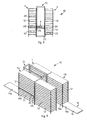
- the number 10 denotes in its entirety an automated store according to the present invention by means of which it is possible to provide to store objects 20, of variable sizes, having at least a substantially plane lower surface, in this case consisting of boxes of a parallelepiped shape.
- the automated store 10 comprises four towers 11, each provided with a plurality of horizontal shelves 12 one above the other, a transfer device 13, a first conveyor belt 14, a second conveyor belt 15, a third conveyor belt 16 and a fourth conveyor belt 17.
- the conveyor belts 14, 15, 16 and 17 have a width substantially equivalent to the width L 2 of the shelves 12 and a direction of advance parallel to the length L 1 of the shelves 12.
- the four towers are disposed two by two aligned with each other on opposite sides with respect to a track 18 along which the transfer device 13 is able to move.
- the first conveyor belt 14 extends for a part 14a outside and for another part 14b inside an inlet tower 11a, advantageously at the height of the lower shelves 12.
- first photocell 19 associated with a digital encoder, able to determine the entity of the advance of the first conveyor belt 14, the function of which will be explained hereafter.
- the first photocell 19 is disposed on an axis X aligned with the left transverse edge 12a of the shelves 12 located above the part 14b of the conveyor belt 14.
- a bar code reader is advantageously present.
- the second conveyor belt 15 extends, at the height of the lower shelves 12, for a part 15a inside an outlet tower 11b and for another part 14b outside the tower 11b, in a position adjacent to the third conveyor belt 16.
- a second photocell 21 also associated with a relative encoder able to determine the entity of the advance of the second conveyor belt 15, as will be described hereafter.
- the third conveyor belt 16 extends as an extension of the second conveyor belt 15 and is provided with a thruster bar 27, having a length substantially equivalent to that of the third conveyor belt 16 and able to move in a direction orthogonal to the direction of advance of the latter.
- the fourth conveyor belt 17 is disposed substantially parallel and adjacent to the third conveyor belt 16.
- the transfer device 13 comprises a slider 22, able to slide along the tracks 18 to move in a direction parallel to the length L 1 of the shelves 12, and a frame 23, mounted on the slider 22, which extends as far as above the towers 11.
- a supporting base 24 is mounted, able to be moved vertically, by suitable actuator members of a substantially known type, to be disposed selectively in a position co-planar with the shelves 12.
- the supporting base 24 has a conformation and surface substantially equal to that of the shelves 12 and is able, according to the position assumed by the slider 22, to be disposed adjacent to and aligned with the shelves 12.
- Two telescopic supports 25 are associated with the supporting base 24, at the ends of which two translation bars 26 are able to be constrained, each of which is able to assume a lowered position, interfering with the objects 20, and a raised position, not interfering with the objects 20.
- the two translation bars 26 are disposed on opposite sides of the supporting base 24, in order to cooperate respectively with the towers 11 located on one side and the other side of the supporting base 24.
- the two translation bars 26 are associated with guides 29, of the cable or chain type, able to move them in coordination with each other, so that when one translation bar 26 is in the lowered position, the other translation bar 26 is in the raised position.
- the telescopic supports 25 are able to selectively extend in both directions, to take the lowered translation bar 26 in correspondence with the outer edge, that is, the edge farthest from the supporting base 24, of the shelves.
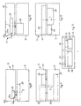
- Fig. 14 shows schematically a pick up step and a positioning step of an object 20 by means of the transfer device 13.
- the slider 22 moves with the supporting base 24 into alignment and a position co-planar with said shelf 12; a first translation bar 26a, facing towards the shelf 12, initially in a lowered position ( fig. 14a ), is raised ( fig. 14b ).
- the telescopic supports 25 are extended, moving above the shelf 12 ( fig. 14c ) and the first translation bar 26a is lowered ( fig. 14d ) so as to bestride the object 20 to be picked up.
- the telescopic supports 25 are then retracted and the first translation bar 26a, constrained to it, thrusts the object 20 onto the supporting base 24, thus completing the pick-up operation ( fig. 14e ).
- the positioning of the object 20 on a shelf 12 is performed, with the supporting base 24 aligned and in a position co-planar with said shelf 12, in this case by raising the second translation bar 26b, facing towards the same shelf 12, and by lowering the first translation bar 26a in order to constrain it to the telescopic supports 25 ( fig. 14e ).
- the telescopic supports 25 are first extended, so that the first translation bar 26a thrusts the object onto the shelf 12 ( fig. 14f ), and then retracted so as to return the translation bars 26a and 26b onto the slider 22 ( fig. 14g ).
- the transfer device 13 the movement members of the conveyor belts 14, 15, 16 and 17, the bar code reader, the encoders associated with the photocells 19 and 21, and the thruster bar 27 are connected to a command and control unit of an electronic type, not shown, provided with memory units in which the sizes, at least in length "a” and width "b", of each type of object 20 are memorized, and also the displacements of the first conveyor belt 14 and of the transfer device 13 for the consequent determination of the spaces occupied by the objects 20 on the shelves 12.
- length "a” and width "b” of the objects 20 we define respectively the sizes occupied in a longitudinal direction, that is, of the length L 1 , and transverse, that is, the width L 2 , of the shelves 12.
- the command and control unit is able to manage automatically the coordinated functioning of the automated store 10 as described hereafter.
- the objects 20 are fed, with a desired cadence, through the first conveyor belt 14, and the relative bar code is read by the appropriate reader, which sends the information to the command and control unit in order to determine at least the size of the object 20 in transit at that moment.
- the passage of the object 20 in front of the first photocell 19 determines the longitudinal bulk, that is, the length "a", of said object 20, and hence its orientation on the first conveyor belt 14.
- This information allows the command and control unit to identify the shelf 12 for which the object 20 is intended and to establish the storage position where said object 20 must be disposed on the relative shelf 12, in particular the distance "D" from a reference transverse edge, in the drawings the left transverse edge 12a of said shelf 12.
- the distance "D” is determined so as to be as small as possible, in order to allow the object 20 to be stored without interference with the structure of the towers 11 and/or with other objects already present on the shelf 12, as will be clarified hereafter. For this reason, when an object 20 must be disposed on an empty shelf 12, the distance "D" is advantageously just a little more than the longitudinal size of the uprights of the towers 11.
- the command and control unit is thus able to calculate the entity of the advance that the first conveyor belt 14 has to make in order to take the object 20 to a desired pick-up position, on the same first conveyor belt 14, and a position of temporary collocation, on the supporting base 24, correlated to the storage position identified and hence to said distance "D".
- the encoder starts to detect the feed of the first conveyor belt 14, supplying the information to the command and control unit; when the encoder has measured an advance of the first conveyor belt 14 equal to the distance "D", the command and control unit immediately determines the stoppage of said first conveyor belt 14.
- the object 20 finds itself in the exact pick-up position, with its rear edge 20a located at distance "D" from the axis X.
- the transfer device 13 is then moved so as to take the supporting base 24 in alignment with the shelves 12 of the first tower 11a and co-planar with the first conveyor belt 14, hence with its left transverse edge 24a aligned with the axis X.
- the object 20 is then drawn and made to slide transversely on the lower plane surface until it is taken onto the supporting base 24, in the position of temporary collocation wherein its rear transverse edge 20a finds itself always at distance "D" from the left transverse edge 24a.
- the transfer device 13 is moved so as to take the supporting base 24 co-planar and in alignment with the shelf 12 to which the object 20 is intended.
- the object 20 is thrust and made to slide transversely by means of the appropriate translation bar 26 until it is disposed completely resting on the shelf 12, in the storage position wherein its rear transverse edge 20a is located at distance "D" from the left transverse edge 12a of said shelf and its longitudinal edge 20b, facing the supporting base 24, is substantially aligned with the corresponding longitudinal front edge 12b of the shelf 12 ( fig. 8 ).
- the command and control unit memorizes the position and the storage space occupied by the object 20 on the shelf 12.
- the transfer device 13 is moved to return the supporting base 24 to a position co-planar with the first conveyor belt 14 in order to pick up another object 20.
- the new object 20 is made to advance on the first conveyor belt 14 until it reaches a pick-up position determined by the command and control unit so that, in its subsequent storage position on the intended shelf 12, it does not interfere with the other objects 20 present on the same shelf 12.
- the pick-up position and the distance "D", and hence the position of temporary collocation of the new object 20 are defined so that, in the storage position, the transverse plane "Z" passing through the baricenter of the object 20 of greater length "a” intersects the object having a smaller length "a” ( figs. 9, 10 and 11 ).
- the new object is transferred by the appropriate translation bar 26 onto the shelf 12 as indicated previously, thrusting the object 20 already present on said shelf.
- the command and control unit determines a pick-up position, and a position of temporary collocation, and then calculates the distance "D", in such a manner that the new object 20 is positioned longitudinally adjacent to the object or objects 20 already present on the shelf 12 ( figs. 6 and 11 ).
- a new object 20 in determining the position of temporary collocation, can be located respectively adjacent transversely and longitudinally to two objects 20 already present on a shelf 12 only if said new object 20 has a width "b" less than the object 20 with which it must be located longitudinally adjacent ( fig. 11 ); this is to prevent, both during the positioning step and also during the pick-up step, any thrust between the objects 20 from determining a disconnected rotation thereof.
- a new object 20 can be disposed on a shelf on which two or more objects 20 are already present only if of these last two the widest object 20 is intersected by the transverse plane "Z" passing through the baricenter of the new object 20 ( fig. 12 ).
- the command and control unit considers the objects 20 transversally adjacent to each other on said shelf 12 as a single virtual object 28 having as a width the sum of the widths "b" of said objects 20 and as a length the greatest of the lengths "a" of said objects 20 ( fig. 13 ).
- the new object 20 cannot be stored on a determinate shelf 12 due to lack of space, the same object 20 is stored on a different shelf 12, chosen by the command and control unit from those to which said specific object 20 may possibly be intended.
- the objects 20 present on a shelf 12 are discharged by means of the transfer device 13 as follows.
- the supporting base 24 is aligned and taken to a position co-planar with the shelf 12 to be emptied; the telescopic supports 25 are extended taking the necessary translation bar 26, in its raised position, beyond the objects 20.
- the translation bar 26 is lowered and the telescopic supports 25 are made to return so as to draw all the objects 20 present on the shelf 12 onto the supporting base 24.
- the supporting base 24 is aligned and disposed co-planar with the portion 15a of the second conveyor belt 15 and the translation bar 26 thrusts the objects 20 onto said portion 15a.
- the second conveyor belt 15 is then driven so as to convey the objects 20 onto the third conveyor belt 16, driven in turn.
- the second conveyor belt 15 can be driven so as to convey without interruptions all the discharged objects 20, or only some of them defining a same virtual object 28.
- the relative encoder starts to detect the advance of the second conveyor belt 15, supplying the information to the command and control unit.
- the command and control unit determines the stoppage when the last object 20 to be transferred is on the third conveyor belt 16.
- the drive of the thruster bar 27 allows to progressively discharge the individual objects 20 belonging to said virtual object 28 through the fourth conveyor belt 17.
- the command and control unit notes the composition and width "b" of the objects 20 belonging to the virtual object 28, determines the movement of the thruster bar 27, with variable pitch according to the width "b", so as to thrust a single object 20 at a time onto the fourth conveyor belt 17.
- first conveyor belt 14 and/or the second conveyor belt 15 there may be respective pairs of conveyor belts having lengths equivalent to each of their parts 14a, 14b, 15a, 15b.
- transport means with horizontal feed of a different type.
- the bar code reader may not be present, for example if there is a system present to identify the objects 20 upstream of the automated store 10.
- the transfer device 13 is provided with a single translation bar 26, by means of which the operations are effected to position the objects 20 on the shelves 12; each shelf 12 is also associated with a respective translation bar 30 by means of which the objects 20 are discharged from the shelf 12.
- the translation bar 26, moving in an upside-down U path along guides 29, is able to be disposed from one end to the other of the telescopic supports 25 in order to be constrained to them.
- the translation bars 30, on the contrary, are mounted idle on respective substantially horizontal guides and are able to be attached to the ends of the telescopic supports 25, to be taken from an advance position, in correspondence with the front longitudinal edge 12b of the relative shelf 12, assumed when there are no objects 20 on the latter, to a retracted position, in correspondence with the rear longitudinal edge 12c of the relative shelf 12, when there are objects 20 on the shelf 12.
- the translation bar 26 is taken to the end of the telescopic supports 25 farthest from said object 20 ( fig. 15b ); then the telescopic supports 25 themselves are extracted towards the object 20 and attach the translation bar 30 of said shelf 12 ( fig. 15c ).
- the telescopic supports 25 are first retracted, so that the translation bar 30 thrusts the object 20 onto the supporting base 24 ( fig. 15d ), then slightly extracted, in order to return and detach the translation bar 30 on the relative shelf 12 ( fig. 15e ), and finally retracted again ( fig. 15f ).
- the translation bar 26 In order to position on a shelf 12 an object 20 located on the supporting base 24, the translation bar 26 is taken and attached to the end of the telescopic supports 25 farthest from said shelf 12 ( fig. 15g ); then the telescopic supports 25 themselves are extracted towards the shelf 12 so as to attach the translation bar 30 ( fig. 15h ) and to thrust it into its retracted position, while simultaneously the translation bar 26 thrusts the object 20 onto said shelf 12 ( fig. 15i ).
- the translation bar 26 is always kept in the lowered position, which allows to contain the bulk in height of the transfer device 13 and thus to reduce the vertical distance between the shelves 12 with a consequent increase in the capacity of the automated store 10.
Abstract
Description
- The present invention concerns an automated store and a method by means of which it is possible to store objects having at least a substantially plane lower surface, also of different shapes and sizes, optimizing the storage spaces.
- Different types of automated stores for storing objects are known, for example of the type disclosed by the
Italian patent n°. 1310573 - The limitation of such known automated stores is that the disposition of the objects on the shelves for which they are intended occurs in such a manner as to create a lot of empty spaces between one object and the other, and hence determines a considerable reduction in the storage capacity of the store.
-
CH-A-680 212 claim 25 and an automated store according to the preamble of claim 1, wherein a horizontal endless chain conveyor is mounted on a movable plane which is disposable along the storage bay and at any shelf height. A transfer unit above the conveyor moves the bundles from the trays of the endless chain to the selected shelf and vice versa. This known automatic store is cumbersome and complicated and cannot permit to contemporaneously transfer a plurality of objects from the movable plane to any shelf and vice versa. - One purpose of the present invention is to achieve an automated store which will allow to store a plurality of objects having at least a substantially plane lower surface, also of different shapes and sizes, on the relative shelves, so as to optimize the storage spaces and to exploit the capacity of the store to the utmost.
- Another purpose of the present invention is to achieve an automated store of the above type, which is structurally simple and functionally effective and reliable, and which allows to store the objects in such a manner as to form homogeneous lots, for example according to their final destination.
- The applicant has devised and embodied the present invention to overcome the shortcomings of the state of the art in order to achieve these purposes and obtain other advantages.
- The purposes of the invention are achieved by the automated store of claim 1 and the method of
claim 25. The dependent claims describe other innovative characteristics of the invention. - The automated store according to the present invention comprises a plurality of shelves, of the fixed type and each having a determinate surface, on which the objects to be stored are able to be disposed, and a transfer device, able to displace each of said objects towards a specific shelf, provided with a supporting base able to be disposed aligned and co-planar with each of the shelves.
- In particular, on the supporting base, which has a surface, or at least a longitudinal dimension, which is substantially equal to that of every shelf, each object is able to be disposed temporarily during its displacement towards the shelf for which it is intended.
- The transfer device comprises translation means able to thrust at least one object at a time from the supporting base to the specific shelf on which it is to be stored, and vice versa.
- According to a variant, at least a part of said translation means are associated with the shelves.
- The automated store according to the present invention also comprises electronic command and control means able to define a position of temporary collocation of the objects on the supporting base according to their destination on the specific shelf and which controls said translation means to thrust said objects onto the relative fixed shelf, in such a manner that the longitudinal edge of said objects facing towards said supporting base is substantially aligned with the longitudinal edge of said fixed shelf facing towards said supporting base.
- Advantageously, the electronic command and control means comprise at least a memorization unit in which the sizes of each of the objects to the stored, and the storage positions of the objects already disposed on the shelves, are able to be memorized.
- In this way, the electronic command and control means defines the position of temporary collocation of the objects to be stored according to their storage position on the specific shelf, so that in the storage position they do not interfere with possible other objects already disposed on the same specific shelf.
- The storage of other objects on the same shelf is subsequently evaluated by the electronic command and control means, according to the transverse and longitudinal sizes of the objects to be stored and the overall bulk of the objects already present on the shelf.
- More in particular, where possible, the objects are located transversely adjacent, in the same row, on the intended shelf, with the new object to the stored which thrusts the other objects located on the same shelf, until its longitudinal edge is aligned with the longitudinal edge of said shelf.
- If this is not possible, the new object to be stored is located longitudinally adjacent, in a new row, with the other objects already present on the shelf.
- If the longitudinal size of the new object to be stored does not even allow it to be located longitudinally adjacent to the other objects, the new object is stored on another shelf chosen by the electronic command and control means from among those where said object may possibly be intended.
- These and other characteristics of the present invention will become apparent from the following description of a preferential form of embodiment, given as a non-restrictive example with reference to the attached drawings wherein:
-
fig. 1 is the front view of an automated store according to the present invention; -
fig. 2 is a plane view of the automated store infig. 1 ; -
fig. 3 is a lateral view of the automated store infig. 1 ; -
fig. 4 is a partial three-dimensional view of the automated store infig. 1 ; -
fig. 5 is a plane schematic view of a shelf of the automated store infig. 1 ; -
fig. 6 is a schematic view of the shelf infig. 5 during the positioning of an object by the transfer device; -
fig. 7 is a schematic view of the shelf infig. 5 during the pick up of the objects disposed thereon by the transfer device; -
figs. 8 ,9, 10, 11 and 12 are variants offig. 6 ; -
fig. 13 is a schematic view of the shelf infig. 5 in the full condition; -
fig. 14 is a schematic and sectioned view of the transfer device during the pick up and positioning of the objects; -
fig. 15 shows a variant offig. 14 . - With reference to the attached drawings, the
number 10 denotes in its entirety an automated store according to the present invention by means of which it is possible to provide to storeobjects 20, of variable sizes, having at least a substantially plane lower surface, in this case consisting of boxes of a parallelepiped shape. - The
automated store 10 comprises fourtowers 11, each provided with a plurality ofhorizontal shelves 12 one above the other, atransfer device 13, afirst conveyor belt 14, asecond conveyor belt 15, athird conveyor belt 16 and afourth conveyor belt 17. - The
conveyor belts shelves 12 and a direction of advance parallel to the length L1 of theshelves 12. - The four towers are disposed two by two aligned with each other on opposite sides with respect to a
track 18 along which thetransfer device 13 is able to move. - The
first conveyor belt 14 extends for apart 14a outside and for anotherpart 14b inside aninlet tower 11a, advantageously at the height of thelower shelves 12. - Between the two
parts first photocell 19, associated with a digital encoder, able to determine the entity of the advance of thefirst conveyor belt 14, the function of which will be explained hereafter. - More in particular, the
first photocell 19 is disposed on an axis X aligned with the lefttransverse edge 12a of theshelves 12 located above thepart 14b of theconveyor belt 14. - Upstream of the first photocell 19 a bar code reader is advantageously present.
- The
second conveyor belt 15 extends, at the height of thelower shelves 12, for apart 15a inside anoutlet tower 11b and for anotherpart 14b outside thetower 11b, in a position adjacent to thethird conveyor belt 16. - Between the
second conveyor belt 15 and thethird conveyor belt 16 there is asecond photocell 21, also associated with a relative encoder able to determine the entity of the advance of thesecond conveyor belt 15, as will be described hereafter. - The
third conveyor belt 16 extends as an extension of thesecond conveyor belt 15 and is provided with athruster bar 27, having a length substantially equivalent to that of thethird conveyor belt 16 and able to move in a direction orthogonal to the direction of advance of the latter. - The
fourth conveyor belt 17 is disposed substantially parallel and adjacent to thethird conveyor belt 16. - The
transfer device 13 comprises aslider 22, able to slide along thetracks 18 to move in a direction parallel to the length L1 of theshelves 12, and aframe 23, mounted on theslider 22, which extends as far as above thetowers 11. - On the frame 23 a supporting
base 24 is mounted, able to be moved vertically, by suitable actuator members of a substantially known type, to be disposed selectively in a position co-planar with theshelves 12. - The supporting
base 24 has a conformation and surface substantially equal to that of theshelves 12 and is able, according to the position assumed by theslider 22, to be disposed adjacent to and aligned with theshelves 12. - Two
telescopic supports 25 are associated with the supportingbase 24, at the ends of which twotranslation bars 26 are able to be constrained, each of which is able to assume a lowered position, interfering with theobjects 20, and a raised position, not interfering with theobjects 20. - More in particular the two
translation bars 26 are disposed on opposite sides of the supportingbase 24, in order to cooperate respectively with thetowers 11 located on one side and the other side of the supportingbase 24. - Advantageously the two
translation bars 26 are associated withguides 29, of the cable or chain type, able to move them in coordination with each other, so that when onetranslation bar 26 is in the lowered position, theother translation bar 26 is in the raised position. - The
telescopic supports 25 are able to selectively extend in both directions, to take the loweredtranslation bar 26 in correspondence with the outer edge, that is, the edge farthest from the supportingbase 24, of the shelves. -
Fig. 14 shows schematically a pick up step and a positioning step of anobject 20 by means of thetransfer device 13. - In order to pick up an
object 20 from ashelf 12, or from thefirst conveyor belt 14, theslider 22 moves with the supportingbase 24 into alignment and a position co-planar with saidshelf 12; afirst translation bar 26a, facing towards theshelf 12, initially in a lowered position (fig. 14a ), is raised (fig. 14b ). - Then the
telescopic supports 25 are extended, moving above the shelf 12 (fig. 14c ) and thefirst translation bar 26a is lowered (fig. 14d ) so as to bestride theobject 20 to be picked up. - The telescopic supports 25 are then retracted and the
first translation bar 26a, constrained to it, thrusts theobject 20 onto the supportingbase 24, thus completing the pick-up operation (fig. 14e ). - The positioning of the
object 20 on ashelf 12 is performed, with the supportingbase 24 aligned and in a position co-planar with saidshelf 12, in this case by raising thesecond translation bar 26b, facing towards thesame shelf 12, and by lowering thefirst translation bar 26a in order to constrain it to the telescopic supports 25 (fig. 14e ). - Then the
telescopic supports 25 are first extended, so that thefirst translation bar 26a thrusts the object onto the shelf 12 (fig. 14f ), and then retracted so as to return the translation bars 26a and 26b onto the slider 22 (fig. 14g ). - According to a variant, there are two pairs of
telescopic supports 25 associated with relative independent translation bars 26, each able to act on thetowers 11 located on a relative side of thetransfer device 13. - The
transfer device 13, the movement members of theconveyor belts photocells thruster bar 27 are connected to a command and control unit of an electronic type, not shown, provided with memory units in which the sizes, at least in length "a" and width "b", of each type ofobject 20 are memorized, and also the displacements of thefirst conveyor belt 14 and of thetransfer device 13 for the consequent determination of the spaces occupied by theobjects 20 on theshelves 12. - In the following description, by length "a" and width "b" of the
objects 20 we define respectively the sizes occupied in a longitudinal direction, that is, of the length L1, and transverse, that is, the width L2, of theshelves 12. - The command and control unit is able to manage automatically the coordinated functioning of the automated
store 10 as described hereafter. - The
objects 20 are fed, with a desired cadence, through thefirst conveyor belt 14, and the relative bar code is read by the appropriate reader, which sends the information to the command and control unit in order to determine at least the size of theobject 20 in transit at that moment. - The passage of the
object 20 in front of thefirst photocell 19 determines the longitudinal bulk, that is, the length "a", of saidobject 20, and hence its orientation on thefirst conveyor belt 14. - This information, together with the bar code previously acquired, allows the command and control unit to identify the
shelf 12 for which theobject 20 is intended and to establish the storage position where saidobject 20 must be disposed on therelative shelf 12, in particular the distance "D" from a reference transverse edge, in the drawings the lefttransverse edge 12a of saidshelf 12. - The distance "D" is determined so as to be as small as possible, in order to allow the
object 20 to be stored without interference with the structure of thetowers 11 and/or with other objects already present on theshelf 12, as will be clarified hereafter. For this reason, when anobject 20 must be disposed on anempty shelf 12, the distance "D" is advantageously just a little more than the longitudinal size of the uprights of thetowers 11. - The command and control unit is thus able to calculate the entity of the advance that the
first conveyor belt 14 has to make in order to take theobject 20 to a desired pick-up position, on the samefirst conveyor belt 14, and a position of temporary collocation, on the supportingbase 24, correlated to the storage position identified and hence to said distance "D". - As soon as the rear
transverse edge 20a of theobject 20 has passed in front of thefirst photocell 19, and hence theentire object 20 has passed before it, the encoder starts to detect the feed of thefirst conveyor belt 14, supplying the information to the command and control unit; when the encoder has measured an advance of thefirst conveyor belt 14 equal to the distance "D", the command and control unit immediately determines the stoppage of saidfirst conveyor belt 14. - In this condition the
object 20 finds itself in the exact pick-up position, with itsrear edge 20a located at distance "D" from the axis X. - The
transfer device 13 is then moved so as to take the supportingbase 24 in alignment with theshelves 12 of thefirst tower 11a and co-planar with thefirst conveyor belt 14, hence with its lefttransverse edge 24a aligned with the axis X. - By means of one of the two
translation bars 26, theobject 20 is then drawn and made to slide transversely on the lower plane surface until it is taken onto the supportingbase 24, in the position of temporary collocation wherein its reartransverse edge 20a finds itself always at distance "D" from the lefttransverse edge 24a. - Then the
transfer device 13 is moved so as to take the supportingbase 24 co-planar and in alignment with theshelf 12 to which theobject 20 is intended. - In this condition, the
object 20 is thrust and made to slide transversely by means of theappropriate translation bar 26 until it is disposed completely resting on theshelf 12, in the storage position wherein its reartransverse edge 20a is located at distance "D" from the lefttransverse edge 12a of said shelf and itslongitudinal edge 20b, facing the supportingbase 24, is substantially aligned with the corresponding longitudinalfront edge 12b of the shelf 12 (fig. 8 ). - According to the displacements of the
transfer device 13, the distance "D" and the size of theobject 20, the command and control unit memorizes the position and the storage space occupied by theobject 20 on theshelf 12. - Then the
transfer device 13 is moved to return the supportingbase 24 to a position co-planar with thefirst conveyor belt 14 in order to pick up anotherobject 20. - The
new object 20 is made to advance on thefirst conveyor belt 14 until it reaches a pick-up position determined by the command and control unit so that, in its subsequent storage position on the intendedshelf 12, it does not interfere with theother objects 20 present on thesame shelf 12. - If the
new object 20 can be placed transversely adjacent to theobject 20 already on theshelf 12, because the sum of the widths "b" of saidobjects 20 is less than or equal to the width L2 of the shelf, the pick-up position and the distance "D", and hence the position of temporary collocation of thenew object 20, are defined so that, in the storage position, the transverse plane "Z" passing through the baricenter of theobject 20 of greater length "a" intersects the object having a smaller length "a" (figs. 9, 10 and 11 ). - In this way, the new object is transferred by the
appropriate translation bar 26 onto theshelf 12 as indicated previously, thrusting theobject 20 already present on said shelf. - On the contrary, if the
new object 20, in consideration of its size, cannot be located transversely adjacent to theobject 20 already present on theshelf 12, the command and control unit determines a pick-up position, and a position of temporary collocation, and then calculates the distance "D", in such a manner that thenew object 20 is positioned longitudinally adjacent to the object or objects 20 already present on the shelf 12 (figs. 6 and11 ). - Advantageously, in determining the position of temporary collocation, a
new object 20 can be located respectively adjacent transversely and longitudinally to twoobjects 20 already present on ashelf 12 only if saidnew object 20 has a width "b" less than theobject 20 with which it must be located longitudinally adjacent (fig. 11 ); this is to prevent, both during the positioning step and also during the pick-up step, any thrust between theobjects 20 from determining a disconnected rotation thereof. - For the same reason, a
new object 20 can be disposed on a shelf on which two ormore objects 20 are already present only if of these last two thewidest object 20 is intersected by the transverse plane "Z" passing through the baricenter of the new object 20 (fig. 12 ). - If the
objects 20 already present on ashelf 12 occupy only a part of the length L1 of saidshelf 12, in order to determine the spaces occupied by theobjects 20, and hence the pick-up position, the position of temporary collocation and storage of anew object 20, the command and control unit considers theobjects 20 transversally adjacent to each other on saidshelf 12 as a singlevirtual object 28 having as a width the sum of the widths "b" of saidobjects 20 and as a length the greatest of the lengths "a" of said objects 20 (fig. 13 ). - When the
new object 20 cannot be stored on adeterminate shelf 12 due to lack of space, thesame object 20 is stored on adifferent shelf 12, chosen by the command and control unit from those to which saidspecific object 20 may possibly be intended. - The
objects 20 present on ashelf 12 are discharged by means of thetransfer device 13 as follows. - The supporting
base 24 is aligned and taken to a position co-planar with theshelf 12 to be emptied; thetelescopic supports 25 are extended taking thenecessary translation bar 26, in its raised position, beyond theobjects 20. - Then the
translation bar 26 is lowered and thetelescopic supports 25 are made to return so as to draw all theobjects 20 present on theshelf 12 onto the supportingbase 24. - Subsequently, the supporting
base 24 is aligned and disposed co-planar with theportion 15a of thesecond conveyor belt 15 and thetranslation bar 26 thrusts theobjects 20 onto saidportion 15a. - The
second conveyor belt 15 is then driven so as to convey theobjects 20 onto thethird conveyor belt 16, driven in turn. - In this step, according to necessity, the
second conveyor belt 15 can be driven so as to convey without interruptions all the discharged objects 20, or only some of them defining a samevirtual object 28. - As soon as the
objects 20 or thevirtual objects 28 pass in front of thesecond photocell 21, the relative encoder starts to detect the advance of thesecond conveyor belt 15, supplying the information to the command and control unit. - According to requirements, and knowing the longitudinal bulk of the
objects 20 orvirtual objects 28 to be transferred to thethird conveyor belt 16, the command and control unit determines the stoppage when thelast object 20 to be transferred is on thethird conveyor belt 16. - If a single
virtual object 28 has been transferred onto thethird conveyor belt 16, the drive of thethruster bar 27 allows to progressively discharge theindividual objects 20 belonging to saidvirtual object 28 through thefourth conveyor belt 17. - In fact, the command and control unit notes the composition and width "b" of the
objects 20 belonging to thevirtual object 28, determines the movement of thethruster bar 27, with variable pitch according to the width "b", so as to thrust asingle object 20 at a time onto thefourth conveyor belt 17. - It is clear, however, that modifications and/or additions of parts or steps may be made to the
automated store 10 as described heretofore and the relative storage method, without departing from the scope of the present invention, which is defined by the appended claims. - For example, instead of the
first conveyor belt 14 and/or thesecond conveyor belt 15, there may be respective pairs of conveyor belts having lengths equivalent to each of theirparts - Or there may be transport means with horizontal feed of a different type.
- Furthermore, the bar code reader may not be present, for example if there is a system present to identify the
objects 20 upstream of the automatedstore 10. - Moreover, there may be a
single translation bar 26 present on thetransfer device 13, able to be guided from one side to the other of the supportingbase 24. - In the variant shown schematically in
fig. 15 , thetransfer device 13 is provided with asingle translation bar 26, by means of which the operations are effected to position theobjects 20 on theshelves 12; eachshelf 12 is also associated with arespective translation bar 30 by means of which theobjects 20 are discharged from theshelf 12. - More in particular, the
translation bar 26, moving in an upside-down U path along guides 29, is able to be disposed from one end to the other of thetelescopic supports 25 in order to be constrained to them. - The translation bars 30, on the contrary, are mounted idle on respective substantially horizontal guides and are able to be attached to the ends of the
telescopic supports 25, to be taken from an advance position, in correspondence with the frontlongitudinal edge 12b of therelative shelf 12, assumed when there are noobjects 20 on the latter, to a retracted position, in correspondence with the rearlongitudinal edge 12c of therelative shelf 12, when there areobjects 20 on theshelf 12. - In order to pick up an
object 20 located on a shelf 12 (fig. 15a ), thetranslation bar 26 is taken to the end of thetelescopic supports 25 farthest from said object 20 (fig. 15b ); then thetelescopic supports 25 themselves are extracted towards theobject 20 and attach thetranslation bar 30 of said shelf 12 (fig. 15c ). - Then the
telescopic supports 25 are first retracted, so that thetranslation bar 30 thrusts theobject 20 onto the supporting base 24 (fig. 15d ), then slightly extracted, in order to return and detach thetranslation bar 30 on the relative shelf 12 (fig. 15e ), and finally retracted again (fig. 15f ). - In order to position on a
shelf 12 anobject 20 located on the supportingbase 24, thetranslation bar 26 is taken and attached to the end of thetelescopic supports 25 farthest from said shelf 12 (fig. 15g ); then thetelescopic supports 25 themselves are extracted towards theshelf 12 so as to attach the translation bar 30 (fig. 15h ) and to thrust it into its retracted position, while simultaneously thetranslation bar 26 thrusts theobject 20 onto said shelf 12 (fig. 15i ). - Finally the
translation bar 30 is detached and thetelescopic supports 25, with thetranslation bar 26 attached, are retracted (fig. 15j ). - In the steps when the
telescopic supports 25 are extended, thetranslation bar 26 is always kept in the lowered position, which allows to contain the bulk in height of thetransfer device 13 and thus to reduce the vertical distance between theshelves 12 with a consequent increase in the capacity of the automatedstore 10. - It is clear that, although the present invention has been described with reference to specific examples, a person of skill in the art shall certainly be able to achieve many other equivalent forms of automated store, and perfect analogous storage methods, having the characteristics as set forth in the claims and hence all coming within the field of protection defined thereby.
Claims (26)
- Automated store for storing individual objects (20) comprising at least a plurality of fixed shelves (12), on which said objects (20) are able to be disposed, and a transfer device (13) able to move each of said objects (20) towards a specific fixed shelf (12), wherein said transfer device (13) comprises a supporting base (24), able to be disposed aligned and co-planar with each of said fixed shelves (12), having at least a size substantially equal to the corresponding size (L1) of each fixed shelf (12) and on which each object (20) is able to be temporarily disposed, wherein translation means (26, 30) are provided to thrust at least one of said objects (20) from said supporting base (24) to said specific fixed shelf (12), and wherein electronic command and control means are provided to define a position of temporary collocation for said objects (20) on said supporting base (24), according to their destination on said specific fixed shelf (12), in order to allow said translation means (26, 30) to thrust said objects (20) into a corresponding storage position on said specific fixed shelf (12) aligned with said position of temporary collocation, characterized in that said translation means (26, 30) are also able to thrust at least one of said objects (20) from said fixed shelves (12) to said supporting base (24) and in that, under the control of said electronic command and control means the translation means (26, 30) thrust said objects (20) onto said fixed shelf (12) until said objects (20) are resting on said fixed shelf (12) and the longitudinal edge (210b) of said objects (20) facing towards said supporting base (24) is substantially aligned with the longitudinal edge (12b) of said fixed shelf (12) facing towards said supporting base (24).
- Automated store as in claim 1, characterized in that said electronic command and control means comprises at least a memorization unit wherein the sizes of each of said objects (20) to be stored on said fixed shelves (12), and the storage positions of the objects (20) already disposed on said fixed shelves (12), are able to be memorized.
- Automated store as in claim 1 or 2, characterized in that said electronic command and control means are able to define said position of temporary collocation of said objects (20) to be stored according to the storage position of said objects (20) on said specific fixed shelf (12) in order to avoid that said objects (20) in said storage position interfere with any possible other objects (20) already disposed on said specific fixed shelf (12).
- Automated store as in claim 2, characterized in that, if on a specific fixed shelf (12) on which a specific object (20) is to be stored there are other objects (20) present, said electronic command and control means determines the position of temporary collocation of said specific object (20) by comparing at least the sum of the transverse size (b) of said specific object (20) and the transverse size (b) of said other objects (20) with the transverse size (L2) of said specific shelf (12).
- Automated store as in claim 4, characterized in that, if the sum of the transverse size (b) of said specific object (20) and the transverse sizes (b) of said other objects (20) is less than the transverse size (L2) of said specific fixed shelf (12), said translation means (26) is able to thrust said specific object (20) towards said other objects (20), displacing said other objects (20) linearly, so as to locate said specific object (20) transversely adjacent to said other objects (20).
- Automated store as in claim 5, characterized in that said electronic command and control means determines the position of temporary collocation of said specific object (20) so that the transverse plane (Z) passing through the baricenter of that object, of either said specific object (20) or said other objects (20), with a greater longitudinal size (a), intersects that object, of either said specific object (20) or said other objects (20), with a smaller longitudinal size (a).
- Automated store as in claim 4, characterized in that, if the sum of the transverse size (b) of said specific object (20) and the transverse sizes (b) of said other Objects (20) is greater than the transverse size (L2) of said specific fixed shelf (12), said electronic command and control means determines the position of temporary collocation of said specific object (20) also by comparing the longitudinal size (a) of said specific object (20) with the difference between the longitudinal size (L1) of said specific fixed shelf (12) and the overall longitudinal bulk of said other objects (20).
- Automated store as in claim 7, characterized in that, if the longitudinal size (a) of said specific object (20) is less than the difference between the longitudinal size (L1) of said specific fixed shelf (12) and the overall longitudinal bulk of said other objects (20), said translation means (26, 30) is able to thrust said specific object (20) to the side of said other objects (20) so as to locate said specific object (20) longitudinally adjacent to said other objects (20).
- Automated store as in claim 7, characterized in that, if the longitudinal size (a) of said specific object (20) is more than the difference between the longitudinal size (L1) of said specific fixed shelf (12) and the overall longitudinal bulk of said other objects (20), said electronic command and control means determiner said position of temporary collocation of said specific object (20) according to a storage position on a different fixed shelf (12).
- Automated store as in any claim from 3 to 9, characterized in that, in the presence of at least a group of objects (20) transversely adjacent to each other on a specific fixed shelf (12), occupying only a part of the length (L1) of said fixed shelf (12), said electronic command and control means defines the position of temporary collocation of a specific object (20) considering said group of objects (20) as a single virtual object (28) having as transverse size the sum of the transverse sizes (b) of said objects (20), and as longitudinal size the greatest of the longitudinal sizes (a) of said objects (20).
- Automated store as in any claim hereinbefore, characterized in that it further comprises at least first transport means (14) with horizontal advance, able to feed said objects (20) towards said transfer device (13):, with respect to which said supporting base (24) is able to be disposed aligned and co-planar.
- Automated store as in claim 11, characterized in that said electronic command and control means is able to determine the stoppage of said first transport means (14) when said objects (20) reach a pick-up position, aligned with said position of temporary collocation, wherein said objects (20) are able to be translated onto said supporting base (24) by said translation means (26, 30).
- Automated store as in claim 12, characterized in that said electronic command and control means is associated with first sensor means (19) able to detect the transit of every individual object (20) on said first transport means (14) in correspondence with a reference axis (X), and encoder means able to detect the entity of the advance of said first transport means (14) after the passage of said individual object (20) in correspondence with said reference axis (x), in order to determine the stoppage thereof when said individual object (20) finds itself at a determinate distance (D) from said reference axis (X) defining said pick-up position.
- Automated store as in claim 13, characterized in that when said supporting base (24) is aligned with said first transport means (14), a transverse edge (24a) of said supporting base (24) is disposed in alignment with said reference axis (X).
- Automated store as in claim 13 or 14 wherein said objects (20) are associated with a relative bar; code, characterized in that said electronic command and control means is connected to bar code reader means, disposed upstream of said first sensor means (19), by means of which at least some data of said objects (20) is identified, such as size, lot, type of construction.
- Automated store as in any claim hereinbefore, wherein said fixed shelves (12) are disposed at different heights, characterized in that said transfer device (13) comprises slider means (22) able to be selectively driven in order to take said supporting base (24) in alignment with each of said fixed shelves (12), and lifting means mounted On said slider means (22), able to be selectively driven in order to take said supporting base (24) to a position co-planar with each of said fixed shelves (12).
- Automated store as in any claim hereinbefore, characterized in that said translation means (26) is mounted on board said transfer device (13) and is able to selectively assume a lowered position and a raised position in order respectively to interfere or not interfere with said objects (20).
- Automated store as in any claim hereinbefore, characterized in that said translation means comprises at least a bar (26, 30), substantially parallel to the longitudinal size (L1) of said fixed shelves (12) and of said supporting base (24), associated with telescopic arms (25) able to move a bar (26, 30) transversely.
- Automated store as in claims 17 and 18, wherein said fixed shelves (12) are disposed on opposite rows with respect to said transfer device (13), characterized in that said translation means comprises a pair of bars (264, 26b) each of which facing towards a row of said fixed shelves (12).
- Automated store as in any claim hereinbefore, characterized in that at least part of said translation means (30) is associated with said fixed shelves (12);.
- Automated store as in any claim hereinbefore, characterized in that said translation means (26, 30) is able to displace simultaneously all the objects (20) stored on a specific fixed shelf (12) in order to dispose them on said supporting base (24).
- Automated store as in claim 11, characterized in that it comprises second transport means (15), with horizontal advance, with respect to which said supporting base (24) is able to be aligned and disposed co-planar, on which said translation means (26) is able to displace said objects (20) so said objects (20) can be discharged.
- Automated store as in claim 22, characterized in that it comprises third transport means (16) associated with relative thrust means (27) on which said objects (20) can be conveyed by said second transport means (15), and fourth transport means (17), adjacent to said third transport means (16), on which said objects (20) can be individually transferred by means of said thrust means (27).
- Automated store as in claim 23, characterized in that it comprises second sensor means (21) able to detect the passage of said objects (20) from said second transport means (15) to said third transport means (16).
- Method to store individual objects (20) on a plurality of fixed shelves (12), each having a determinate surface, by means of a transfer device (13) able to displace each of said objects (20) towards a specific fixed shelf (12), under the control of electronic command and control means, wherein it comprises at least the following steps:- to dispose each object (20) on a supporting base (24) of said transfer device (13), able to be disposed aligned and co-planar with each of said fixed shelves (12), in a position of temporary collocation determined according to the destination of said object (20) on said specific fixed shelf (12);- to take said supporting base (24) to a position aligned and co-planar with said specific fixed shelf (12);- to thrust at least one of said objects (20), by means of translation means (26, 30), to a relative storage position on said specific fixed shelf (12) aligned with said position of temporary collocation, characterized in that it further comprises the following step:- to thrust, by means of said translation means (26, 30), said objects (20) onto said fixed shelf (12) until said objects (20) are resting on said fixed shelf (12) and the longitudinal edge (20b) of said objects (20) facing towards said supporting base (24) is substantially aligned with the longitudinal edge (12b) of said' fixed shelf (12) facing towards said supporting base (24).
- Method as in claim 25, characterized in that, upstream of said steps, it comprises at least the following further steps:- to dispose said object (20) in a pick-up position aligned with said position of temporary collocation;- to thrust said object (20) by means of said translation means (26, 30), in order to take it from said pick-up position to said position of temporary collocation.
Priority Applications (2)
| Application Number | Priority Date | Filing Date | Title |
|---|---|---|---|
| SI200630048T SI1764317T1 (en) | 2005-11-24 | 2006-10-26 | Automated store and corresponding method to store objects |
| PL06122986T PL1764317T3 (en) | 2005-11-24 | 2006-10-26 | Automated store and corresponding method to store objects |
Applications Claiming Priority (1)
| Application Number | Priority Date | Filing Date | Title |
|---|---|---|---|
| IT000199A ITUD20050199A1 (en) | 2005-11-24 | 2005-11-24 | AUTOMATED WAREHOUSE AND RELATED STORAGE PROCEDURE |
Publications (2)
| Publication Number | Publication Date |
|---|---|
| EP1764317A1 EP1764317A1 (en) | 2007-03-21 |
| EP1764317B1 true EP1764317B1 (en) | 2008-04-16 |
Family
ID=35892579
Family Applications (1)
| Application Number | Title | Priority Date | Filing Date |
|---|---|---|---|
| EP06122986A Active EP1764317B1 (en) | 2005-11-24 | 2006-10-26 | Automated store and corresponding method to store objects |
Country Status (11)
| Country | Link |
|---|---|
| US (1) | US7890206B2 (en) |
| EP (1) | EP1764317B1 (en) |
| CN (1) | CN1970406B (en) |
| AT (1) | ATE392377T1 (en) |
| DE (1) | DE602006000935T2 (en) |
| DK (1) | DK1764317T3 (en) |
| ES (1) | ES2308673T3 (en) |
| IT (1) | ITUD20050199A1 (en) |
| PL (1) | PL1764317T3 (en) |
| PT (1) | PT1764317E (en) |
| SI (1) | SI1764317T1 (en) |
Families Citing this family (16)
| Publication number | Priority date | Publication date | Assignee | Title |
|---|---|---|---|---|
| ITUD20070196A1 (en) * | 2007-10-24 | 2009-04-25 | Baccini S P A | AUTOMATIC WAREHOUSE AND PROCEDURE FOR STORAGE OF ELECTRONIC CIRCUIT PLATES |
| AT506284A1 (en) * | 2007-12-21 | 2009-07-15 | Tgw Mechanics Gmbh | METHOD FOR STORING LOADING TOOLS AND TRANSPORT DEVICE |
| AT506221B1 (en) | 2008-01-11 | 2009-07-15 | Tgw Mechanics Gmbh | METHOD AND TRANSPORT DEVICE FOR POSITIONING LOADING TOOLS BEFORE DELIVERY INTO A SHELF COMPARTMENT |
| ITMO20080036A1 (en) * | 2008-02-04 | 2009-08-05 | S I T I Di Basso S R L | LOADING AND UNLOADING DEVICE FOR A TRASLOELEVATORE APPARATUS |
| CN102173334B (en) * | 2011-02-09 | 2012-11-07 | 广运机电(苏州)有限公司 | Automatic storing and fetching system of stereoscopic warehouse |
| EP2808831B1 (en) * | 2012-01-26 | 2017-03-08 | Hanmi IT Co., Ltd. | Scanner, scanning apparatus and scanning method for a shelf |
| CN102826318B (en) * | 2012-08-16 | 2015-04-29 | 常州天合光能有限公司 | Photovoltaic module testing system with standard component storage device |
| DE102015213546B4 (en) * | 2015-07-17 | 2022-03-31 | Cewe Stiftung & Co. Kgaa | Shelving system for storing and retrieving objects |
| CN105253513B (en) * | 2015-11-03 | 2017-08-25 | 国网山东济南市历城区供电公司 | Electric energy meter storing unit |
| CN105438707B (en) * | 2015-12-23 | 2017-10-17 | 贵阳普天物流技术有限公司 | A kind of method and device of intensive warehouse automatic access goods |
| CN109279371B (en) * | 2017-07-19 | 2021-01-15 | 苏州喜和喜精密机械有限公司 | Intelligent optical self-propelled stacker crane |
| CN109081036B (en) * | 2018-08-31 | 2023-08-18 | 上海擅韬信息技术有限公司 | Automatic medicine dispensing machine medicine dispensing system and medicine dispensing method thereof |
| CN109279247B (en) * | 2018-10-08 | 2021-05-04 | 深圳市智佳能自动化有限公司 | Automatic logistics warehousing system |
| CN109353737B (en) * | 2018-11-08 | 2020-07-28 | 醴陵市绿源商贸有限公司 | Intelligent warehousing lateral warehousing method and intelligent warehousing |
| CH717348A1 (en) * | 2020-04-27 | 2021-10-29 | Ferag Ag | Method for operating a transport device with a storage device and such a transport device. |
| TWI757826B (en) * | 2020-08-13 | 2022-03-11 | 所羅門股份有限公司 | Automatic storage method and system |
Family Cites Families (17)
| Publication number | Priority date | Publication date | Assignee | Title |
|---|---|---|---|---|
| GB1254387A (en) | 1969-05-05 | 1971-11-24 | Eaton Yale & Towne | Warehousing apparatus |
| JPS5912005A (en) | 1982-07-09 | 1984-01-21 | Kao Corp | Case supply machine |
| CH680212A5 (en) * | 1990-03-16 | 1992-07-15 | Fritschi Ag Hugo | Shelf service equipment for high level shelf storage - enables bundles to circulate on intermediate storage conveyor which allows access to other bundles behind them |
| CA2096703A1 (en) * | 1993-04-02 | 1994-10-03 | Kurt M. Lloyd | Automatic storage and retrieval system |
| ES2104219T5 (en) * | 1993-04-10 | 2002-04-01 | Christoph Schausten | PROCEDURE FOR STORAGE OF PACKED MATERIAL AND DEVICE FOR THE PERFORMANCE OF THE PROCEDURE. |
| DE4320402A1 (en) | 1993-06-19 | 1994-12-22 | Noell Gmbh | Pull-out unit for containers |
| DE19507479C2 (en) | 1995-03-03 | 1998-12-24 | Siemens Ag | Device for loading trays |
| DE19507480C2 (en) | 1995-03-03 | 1999-06-10 | Siemens Ag | Device for unloading trays |
| DE19509951C2 (en) * | 1995-03-18 | 1997-03-13 | Rudolf M Dipl Ing Wagner | Device for unsorted storage of goods or other objects |
| JP2946281B2 (en) | 1995-04-20 | 1999-09-06 | トーヨーカネツ株式会社 | Stacker crane |
| US6089819A (en) * | 1997-08-18 | 2000-07-18 | Hk Systems, Inc. | Method and apparatus for palletizing and depalletizing layers of articles on stackable pallets |
| IT1310573B1 (en) | 1999-06-11 | 2002-02-19 | Rgs Automazioni Srl | AUTOMATED WAREHOUSE |
| US20050149226A1 (en) * | 2002-04-09 | 2005-07-07 | Ebox, Inc. | Warehousing system and method |
| EP1273531A1 (en) * | 2001-07-02 | 2003-01-08 | Crisplant A/S | A storage system for storing items to be distributed |
| US7184855B2 (en) * | 2002-03-13 | 2007-02-27 | Stingel Iii Frederick J | Automated container storage and delivery system |
| JP2004284772A (en) * | 2003-03-24 | 2004-10-14 | Toshiba Mitsubishi-Electric Industrial System Corp | Board transporting system |
| US7266422B1 (en) * | 2004-04-09 | 2007-09-04 | Fanuc Robotics America, Inc. | Automated palletizing cases having mixed sizes and shapes |
-
2005
- 2005-11-24 IT IT000199A patent/ITUD20050199A1/en unknown
-
2006
- 2006-10-26 PT PT06122986T patent/PT1764317E/en unknown
- 2006-10-26 ES ES06122986T patent/ES2308673T3/en active Active
- 2006-10-26 AT AT06122986T patent/ATE392377T1/en active
- 2006-10-26 DE DE602006000935T patent/DE602006000935T2/en active Active
- 2006-10-26 PL PL06122986T patent/PL1764317T3/en unknown
- 2006-10-26 DK DK06122986T patent/DK1764317T3/en active
- 2006-10-26 SI SI200630048T patent/SI1764317T1/en unknown
- 2006-10-26 EP EP06122986A patent/EP1764317B1/en active Active
- 2006-11-24 CN CN2006101467859A patent/CN1970406B/en active Active
- 2006-11-24 US US11/604,115 patent/US7890206B2/en active Active
Also Published As
| Publication number | Publication date |
|---|---|
| ITUD20050199A1 (en) | 2007-05-25 |
| CN1970406A (en) | 2007-05-30 |
| SI1764317T1 (en) | 2008-10-31 |
| PT1764317E (en) | 2008-07-24 |
| PL1764317T3 (en) | 2008-09-30 |
| DE602006000935D1 (en) | 2008-05-29 |
| DK1764317T3 (en) | 2008-08-18 |
| EP1764317A1 (en) | 2007-03-21 |
| CN1970406B (en) | 2011-05-04 |
| DE602006000935T2 (en) | 2009-05-28 |
| US7890206B2 (en) | 2011-02-15 |
| ES2308673T3 (en) | 2008-12-01 |
| US20070116544A1 (en) | 2007-05-24 |
| ATE392377T1 (en) | 2008-05-15 |
Similar Documents
| Publication | Publication Date | Title |
|---|---|---|
| EP1764317B1 (en) | Automated store and corresponding method to store objects | |
| CN107667061B (en) | Method and storage system for storing piece goods in a rack | |
| US5087169A (en) | Palletizing robot | |
| JP5605430B2 (en) | Automated warehouse and how to enter the automated warehouse | |
| US8740542B2 (en) | Method for introducing loading auxiliary means of transport device | |
| US20100272546A1 (en) | Method and transport device for positioning loading aids prior to the transfer thereof into a shelf | |
| JP5418825B2 (en) | Article transfer device and stacker crane equipped with the same | |
| NL8801059A (en) | Apparatus for stacking bundles of corrugated cardboard flat-folded boxes. | |
| CN217050074U (en) | Robot, workbin transfer device and workbin transfer system | |
| CN210028822U (en) | Stereoscopic warehouse fork | |
| EP1842803B1 (en) | An automatic warehouse | |
| CN207107794U (en) | A kind of sheet material pipeline track separation mechanism | |
| JP3924520B2 (en) | Automatic warehouse | |
| JPH0215441B2 (en) | ||
| CN207107856U (en) | A kind of three-dimensional storing mechanism of sheet material | |
| CN116946590A (en) | Flexible goods shelf storage system with multiple equipment combinations | |
| JP3766587B2 (en) | Automatic warehouse | |
| CN208326375U (en) | A kind of vertical distraction formula logistic storage system | |
| CN220663696U (en) | Ultra-large storage machine | |
| CN207293508U (en) | Fingerprint module collecting machine | |
| JP2003246413A (en) | Storage facility | |
| CN111620013A (en) | Stacker, get and put equipment and stereoscopic warehouse | |
| CN218664287U (en) | Plate folding device for producing gypsum plasterboards | |
| CN113247503B (en) | Plate storage warehouse, production line and ex-warehouse method | |
| CN107352260A (en) | Fingerprint module collecting machine |
Legal Events
| Date | Code | Title | Description |
|---|---|---|---|
| PUAI | Public reference made under article 153(3) epc to a published international application that has entered the european phase |
Free format text: ORIGINAL CODE: 0009012 |
|
| AK | Designated contracting states |
Kind code of ref document: A1 Designated state(s): AT BE BG CH CY CZ DE DK EE ES FI FR GB GR HU IE IS IT LI LT LU LV MC NL PL PT RO SE SI SK TR |
|
| AX | Request for extension of the european patent |
Extension state: AL BA HR MK YU |
|
| 17P | Request for examination filed |
Effective date: 20070710 |
|
| GRAP | Despatch of communication of intention to grant a patent |
Free format text: ORIGINAL CODE: EPIDOSNIGR1 |
|
| AKX | Designation fees paid |
Designated state(s): AT BE BG CH CY CZ DE DK EE ES FI FR GB GR HU IE IS IT LI LT LU LV MC NL PL PT RO SE SI SK TR |
|
| GRAS | Grant fee paid |
Free format text: ORIGINAL CODE: EPIDOSNIGR3 |
|
| GRAA | (expected) grant |
Free format text: ORIGINAL CODE: 0009210 |
|
| AK | Designated contracting states |
Kind code of ref document: B1 Designated state(s): AT BE BG CH CY CZ DE DK EE ES FI FR GB GR HU IE IS IT LI LT LU LV MC NL PL PT RO SE SI SK TR |
|
| REG | Reference to a national code |
Ref country code: CH Ref legal event code: EP |
|
| REG | Reference to a national code |
Ref country code: IE Ref legal event code: FG4D |
|
| REF | Corresponds to: |
Ref document number: 602006000935 Country of ref document: DE Date of ref document: 20080529 Kind code of ref document: P |
|
| REG | Reference to a national code |
Ref country code: RO Ref legal event code: EPE |
|
| REG | Reference to a national code |
Ref country code: PT Ref legal event code: SC4A Free format text: AVAILABILITY OF NATIONAL TRANSLATION Effective date: 20080715 |
|
| REG | Reference to a national code |
Ref country code: CH Ref legal event code: NV Representative=s name: R. A. EGLI & CO. PATENTANWAELTE |
|
| REG | Reference to a national code |
Ref country code: SE Ref legal event code: TRGR |
|
| REG | Reference to a national code |
Ref country code: DK Ref legal event code: T3 |
|
| REG | Reference to a national code |
Ref country code: GR Ref legal event code: EP Ref document number: 20080401819 Country of ref document: GR |
|
| REG | Reference to a national code |
Ref country code: PL Ref legal event code: T3 |
|
| REG | Reference to a national code |
Ref country code: EE Ref legal event code: FG4A Ref document number: E002300 Country of ref document: EE Effective date: 20080729 |
|
| PG25 | Lapsed in a contracting state [announced via postgrant information from national office to epo] |
Ref country code: FI Free format text: LAPSE BECAUSE OF FAILURE TO SUBMIT A TRANSLATION OF THE DESCRIPTION OR TO PAY THE FEE WITHIN THE PRESCRIBED TIME-LIMIT Effective date: 20080416 |
|
| REG | Reference to a national code |
Ref country code: HU Ref legal event code: AG4A Ref document number: E003761 Country of ref document: HU |
|
| REG | Reference to a national code |
Ref country code: ES Ref legal event code: FG2A Ref document number: 2308673 Country of ref document: ES Kind code of ref document: T3 |
|
| PG25 | Lapsed in a contracting state [announced via postgrant information from national office to epo] |
Ref country code: IS Free format text: LAPSE BECAUSE OF FAILURE TO SUBMIT A TRANSLATION OF THE DESCRIPTION OR TO PAY THE FEE WITHIN THE PRESCRIBED TIME-LIMIT Effective date: 20080816 |
|
| ET | Fr: translation filed | ||
| PLBE | No opposition filed within time limit |
Free format text: ORIGINAL CODE: 0009261 |
|
| STAA | Information on the status of an ep patent application or granted ep patent |
Free format text: STATUS: NO OPPOSITION FILED WITHIN TIME LIMIT |
|
| 26N | No opposition filed |
Effective date: 20090119 |
|
| PG25 | Lapsed in a contracting state [announced via postgrant information from national office to epo] |
Ref country code: MC Free format text: LAPSE BECAUSE OF NON-PAYMENT OF DUE FEES Effective date: 20081031 |
|
| PG25 | Lapsed in a contracting state [announced via postgrant information from national office to epo] |
Ref country code: CY Free format text: LAPSE BECAUSE OF FAILURE TO SUBMIT A TRANSLATION OF THE DESCRIPTION OR TO PAY THE FEE WITHIN THE PRESCRIBED TIME-LIMIT Effective date: 20080416 |
|
| PG25 | Lapsed in a contracting state [announced via postgrant information from national office to epo] |
Ref country code: LU Free format text: LAPSE BECAUSE OF NON-PAYMENT OF DUE FEES Effective date: 20081026 |
|
| REG | Reference to a national code |
Ref country code: FR Ref legal event code: PLFP Year of fee payment: 10 |
|
| REG | Reference to a national code |
Ref country code: FR Ref legal event code: PLFP Year of fee payment: 11 |
|
| REG | Reference to a national code |
Ref country code: FR Ref legal event code: PLFP Year of fee payment: 12 |
|
| REG | Reference to a national code |
Ref country code: FR Ref legal event code: PLFP Year of fee payment: 13 |
|
| REG | Reference to a national code |
Ref country code: EE Ref legal event code: HC1A Ref document number: E002300 Country of ref document: EE |
|
| PGFP | Annual fee paid to national office [announced via postgrant information from national office to epo] |
Ref country code: NL Payment date: 20221012 Year of fee payment: 17 Ref country code: FR Payment date: 20221010 Year of fee payment: 17 |
|
| PGFP | Annual fee paid to national office [announced via postgrant information from national office to epo] |
Ref country code: TR Payment date: 20221014 Year of fee payment: 17 Ref country code: SK Payment date: 20221017 Year of fee payment: 17 Ref country code: RO Payment date: 20221024 Year of fee payment: 17 Ref country code: PT Payment date: 20221014 Year of fee payment: 17 Ref country code: LV Payment date: 20221024 Year of fee payment: 17 Ref country code: LT Payment date: 20221014 Year of fee payment: 17 Ref country code: IE Payment date: 20221005 Year of fee payment: 17 Ref country code: GB Payment date: 20221028 Year of fee payment: 17 Ref country code: EE Payment date: 20221025 Year of fee payment: 17 Ref country code: DK Payment date: 20221011 Year of fee payment: 17 Ref country code: DE Payment date: 20220729 Year of fee payment: 17 Ref country code: CZ Payment date: 20221024 Year of fee payment: 17 Ref country code: BG Payment date: 20221024 Year of fee payment: 17 Ref country code: AT Payment date: 20221005 Year of fee payment: 17 |
|
| PGFP | Annual fee paid to national office [announced via postgrant information from national office to epo] |
Ref country code: SI Payment date: 20221013 Year of fee payment: 17 Ref country code: PL Payment date: 20221013 Year of fee payment: 17 Ref country code: HU Payment date: 20221018 Year of fee payment: 17 Ref country code: GR Payment date: 20221026 Year of fee payment: 17 Ref country code: CH Payment date: 20221014 Year of fee payment: 17 Ref country code: BE Payment date: 20221012 Year of fee payment: 17 |
|
| P01 | Opt-out of the competence of the unified patent court (upc) registered |
Effective date: 20230515 |
|
| PGFP | Annual fee paid to national office [announced via postgrant information from national office to epo] |
Ref country code: IT Payment date: 20230809 Year of fee payment: 18 |
|
| PGFP | Annual fee paid to national office [announced via postgrant information from national office to epo] |
Ref country code: ES Payment date: 20231108 Year of fee payment: 18 |
|
| PGFP | Annual fee paid to national office [announced via postgrant information from national office to epo] |
Ref country code: SE Payment date: 20231012 Year of fee payment: 18 |
|
| PGFP | Annual fee paid to national office [announced via postgrant information from national office to epo] |
Ref country code: PL Payment date: 20231005 Year of fee payment: 18 |