EP1764252A2 - Zarge für ein Kühlmodul eines Kraftfahrzeuges - Google Patents
Zarge für ein Kühlmodul eines Kraftfahrzeuges Download PDFInfo
- Publication number
- EP1764252A2 EP1764252A2 EP06018939A EP06018939A EP1764252A2 EP 1764252 A2 EP1764252 A2 EP 1764252A2 EP 06018939 A EP06018939 A EP 06018939A EP 06018939 A EP06018939 A EP 06018939A EP 1764252 A2 EP1764252 A2 EP 1764252A2
- Authority
- EP
- European Patent Office
- Prior art keywords
- frame
- support elements
- frame according
- cooling module
- pivot
- Prior art date
- Legal status (The legal status is an assumption and is not a legal conclusion. Google has not performed a legal analysis and makes no representation as to the accuracy of the status listed.)
- Granted
Links
- 238000001816 cooling Methods 0.000 title claims description 34
- 238000002347 injection Methods 0.000 claims description 2
- 239000007924 injection Substances 0.000 claims description 2
- 239000002826 coolant Substances 0.000 description 8
- 238000009434 installation Methods 0.000 description 8
- 239000003507 refrigerant Substances 0.000 description 4
- 238000002485 combustion reaction Methods 0.000 description 1
- 230000001419 dependent effect Effects 0.000 description 1
- 238000003780 insertion Methods 0.000 description 1
- 230000037431 insertion Effects 0.000 description 1
Images

Classifications
-
- B—PERFORMING OPERATIONS; TRANSPORTING
- B62—LAND VEHICLES FOR TRAVELLING OTHERWISE THAN ON RAILS
- B62D—MOTOR VEHICLES; TRAILERS
- B62D25/00—Superstructure or monocoque structure sub-units; Parts or details thereof not otherwise provided for
- B62D25/08—Front or rear portions
- B62D25/082—Engine compartments
- B62D25/084—Radiator supports
-
- F—MECHANICAL ENGINEERING; LIGHTING; HEATING; WEAPONS; BLASTING
- F28—HEAT EXCHANGE IN GENERAL
- F28F—DETAILS OF HEAT-EXCHANGE AND HEAT-TRANSFER APPARATUS, OF GENERAL APPLICATION
- F28F9/00—Casings; Header boxes; Auxiliary supports for elements; Auxiliary members within casings
- F28F9/001—Casings in the form of plate-like arrangements; Frames enclosing a heat exchange core
- F28F9/002—Casings in the form of plate-like arrangements; Frames enclosing a heat exchange core with fastening means for other structures
-
- F—MECHANICAL ENGINEERING; LIGHTING; HEATING; WEAPONS; BLASTING
- F01—MACHINES OR ENGINES IN GENERAL; ENGINE PLANTS IN GENERAL; STEAM ENGINES
- F01P—COOLING OF MACHINES OR ENGINES IN GENERAL; COOLING OF INTERNAL-COMBUSTION ENGINES
- F01P2070/00—Details
- F01P2070/50—Details mounting fans to heat-exchangers
-
- F—MECHANICAL ENGINEERING; LIGHTING; HEATING; WEAPONS; BLASTING
- F01—MACHINES OR ENGINES IN GENERAL; ENGINE PLANTS IN GENERAL; STEAM ENGINES
- F01P—COOLING OF MACHINES OR ENGINES IN GENERAL; COOLING OF INTERNAL-COMBUSTION ENGINES
- F01P5/00—Pumping cooling-air or liquid coolants
- F01P5/02—Pumping cooling-air; Arrangements of cooling-air pumps, e.g. fans or blowers
- F01P5/06—Guiding or ducting air to, or from, ducted fans
Definitions
- the invention relates to a frame for a cooling module of a motor vehicle according to the preamble of claim 1.
- Frames or fan frames are used in cooling modules or coolant radiators for motor vehicles and serve on the one hand to guide the sucked by a fan through the radiator or the heat exchanger cooling air and the holder of an electric motor which drives the fan.
- Frames serve in modules that form a unit of different heat exchangers, also for receiving and fixing the heat exchanger.
- the frame which is preferably designed as a plastic injection molded part, a frame with molded fastening means, whereby a simple assembly of the heat exchanger is possible.
- the cooling module is installed in the front region of the engine compartment of the motor vehicle and fastened there relative to the body of the vehicle.
- pipes and hoses When installing the cooling module, pipes and hoses must be connected to the individual heat exchangers, eg coolant hoses, refrigerant pipes, charge air hoses or oil pipes. Furthermore, electrical connections are to be installed, eg. B. for the electric motor of the cooling fan. In general, one has first attached the cooling module at its intended storage locations in the vehicle and then made the necessary hose and pipe connections. However, sufficient space must be provided for the installation of the connections Vehicle be present, which is increasingly no longer the case due to cramped installation conditions.
- laterally projecting support elements are releasably secured to the frame, which is part of the cooling module and this carries.
- the preferably pivotally mounted support elements can, if necessary, d. H. attached during assembly of the cooling module to the frame, for example, inserted and removed after assembly by a simple pivoting movement again.
- the support elements are supported during assembly on parts of the vehicle body, in particular their side members, which are located in the region of the cooling module, so that the cooling module is temporarily held in a mounting position.
- the support elements are adapted to the installation conditions in the vehicle so that the cooling module can be placed during assembly in a position which leaves enough space for the connection work of the fitter.
- the advantage is achieved that a fast and secure installation, in particular the connection of hose and pipe connections is made possible to the heat exchanger.
- the support aids are pivoted, folded and / or removed, and the cooling module is mounted in the vehicle at its intended storage position.
- attachment projections in the form of brackets for receiving the support elements are provided laterally on the frame, which in turn have a pivot pin.
- the support elements which preferably about an approximately vertical axis are pivotable, thus acting as extend and retractable pivot arms, wherein the pivoting range between the mounting position and the position in which the support members are removed, is about 90 °. This pivoting movement and the removal or removal of the support elements is made by the fitter by hand without tools.
- the support elements are thus reusable for a new cooling module to be mounted.
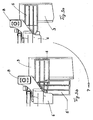
- Fig. 1 shows a cooling module 1 for installation in a motor vehicle, of which parts of the body in the form of longitudinal members 2, 3 are shown.
- the cooling module 1 is supported by two laterally arranged, pivotable support elements 4, 5 relative to the longitudinal members 2, 3.
- the support is temporarily for the assembly, ie the support elements 4, 5 are on the side rails 2, 3, so that the cooling module 1 is held in an approximately vertical position
- the cooling module 1 has a frame 6 which, on the one hand, carries a cooling fan 7 and, on the other hand, two heat exchangers, a coolant cooler 8 and a condenser 9, which are largely covered by the frame 6.
- the coolant cooler 8 has a coolant connection pipe 8a for connection to a coolant circuit, not shown, of the internal combustion engine
- the condenser 9 has a connection flange 9a for connection to a not shown refrigerant circuit of an air conditioner.
- the electric motor of the cooling fan 7 has an electrical plug contact 7a for the power supply.
- the frame 6 has three unspecified bearings or bearings A, B, C, via which the cooling module 1 is mounted after mounting the connection connections in the vehicle. In their side areas, the frame 6 console-like fastening lugs 10, 11, in which the pivotable support elements 4, 5 are inserted.
- Fig. 2 shows the pivotable support member 4 as a single part, ie in the disassembled state.
- the support member 4 is formed as a pivot arm with a - in the installed state - approximately vertically extending pivot axis a, in the region of a pivot pin 12 is arranged with locking element 13.
- the pivot arm 4 has an upper and a lower support surface 4a, 4b.
- the support elements 4, 5, which are of identical design, can be fastened in positions rotated by 180 ° on the frame 6.
- the mounting pin 12 is laterally inserted into an opening, not shown, of the mounting bracket 10, ie transversely to the pivot axis a and thus forms a pivot bearing.
- the locking element 13 which engages over the attachment bracket 10 secures the support element 4.
- Both pivot arms 4, 5 are attached to the frame 6 before the cooling module 1 is mounted in the vehicle.
- Fig. 3a shows the pivot arm 5 as a section in a view from above in the mounting position, ie lying on the side member 3.
- the pivot arm 5 is mounted below the bearing B on the frame 6 in the region of the pitch axis, so that the cooling module is held in an approximately vertical position.
- Fig. 3b shows the pivot arm 5 'in pivoted position, that is pivoted by 90 ° relative to the position 5 in Fig. 3a.
- the pivoted-in pivot arm 5 ' is thus in a position within the two side members and can be removed.
- the swivel arm 4 can be folded in and removed.
- the assembly and installation of the cooling module 1 is carried out essentially in two steps: first, the two pivot arms 4, 5 are attached to the frame 6 and brought into their laterally extended position. Then, the cooling module 1 via the pivot arms 4, 5 so deposited on the side rails 2, 3, that on the side of the connections enough space for mounting remains.
- a coolant hose of the Coolant circuit connected to the connecting piece 8a.
- the refrigerant pipes of the refrigerant circuit are connected to the connecting flange 9a of the condenser.
- an electrical connector with the connector 7a for the electric motor of the blower 7 can be made.
- additional connections can be mounted in this mounting section. After completion of the connection connections, the cooling module 1 is lifted off the longitudinal members 2, 3, the pivot arms 4, 5 are folded in and removed, and the cooling module 1 is fastened in its end position in the motor vehicle, for example via the bearing points A, B shown in FIG , C.
Landscapes
- Engineering & Computer Science (AREA)
- Mechanical Engineering (AREA)
- Chemical & Material Sciences (AREA)
- Combustion & Propulsion (AREA)
- Transportation (AREA)
- Physics & Mathematics (AREA)
- Thermal Sciences (AREA)
- General Engineering & Computer Science (AREA)
- Cooling, Air Intake And Gas Exhaust, And Fuel Tank Arrangements In Propulsion Units (AREA)
- Motor Or Generator Cooling System (AREA)
- Motor Or Generator Frames (AREA)
Abstract
Description
- Die Erfindung betrifft eine Zarge für ein Kühlmodul eines Kraftfahrzeuges nach dem Oberbegriff des Patentanspruches 1.
- Zargen oder Lüfterzargen werden bei Kühlmodulen oder Kühlmittelkühlern für Kraftfahrzeuge verwendet und dienen einerseits der Führung der von einem Lüfter durch den Kühler oder die Wärmeübertrager angesaugten Kühlluft sowie der Halterung eines Elektromotors, welcher den Lüfter antreibt. Zargen dienen bei Modulen, welche eine Baueinheit von verschiedenen Wärmeübertragern bilden, auch zur Aufnahme und Befestigung der Wärmeübertrager. Hierfür weist die Zarge, welche vorzugsweise als Kunststoffspritzteil ausgebildet ist, einen Rahmen mit angespritzten Befestigungsmitteln auf, wodurch eine einfache Montage der Wärmeübertrager möglich ist. Das Kühlmodul wird im vorderen Bereich des Motorraumes des Kraftfahrzeuges eingebaut und dort gegenüber der Karosserie des Fahrzeuges befestigt. Bei der Montage des Kühlmoduls müssen Leitungen und Schläuche an die einzelnen Wärmeübertrager angeschlossen werden, also beispielsweise Kühlmittelschläuche, Kältemittelleitungen, Ladeluftschläuche oder Ölleitungen. Femer sind elektrische Anschlüsse zu montieren, z. B. für den Elektromotor des Kühlgebläses. In der Regel hat man zunächst das Kühlmodul an seinen vorgesehenen Lagerstellen im Fahrzeug befestigt und anschließend die erforderlichen Schlauch- und Leitungsverbindungen hergestellt. Für die Montage der Anschlüsse muss jedoch hinreichend Platz im Fahrzeug vorhanden sein, was aufgrund beengter Einbauverhältnisse zunehmend nicht mehr der Fall ist.
- Es ist Aufgabe der vorliegenden Erfindung, ein Kühlmodul bzw. eine Zarge für ein Kühlmodul derart zu gestalten, dass eine einfache und schnelle Montage, insbesondere die Montage von Anschlüssen für die Wärmeübertrager möglich ist.
- Die Aufgabe der Erfindung wird durch die Merkmale des Patentanspruches 1 gelöst. Vorteilhafte Ausgestaltungen der Erfindung ergeben sich aus den Unteransprüchen.
- Erfindungsgemäß sind an der Zarge, welche Teil des Kühlmoduls ist und dieses trägt, seitlich abragende Stützelemente lösbar befestigt. Die vorzugsweise schwenkbar angeordneten Stützelemente können bei Bedarf, d. h. bei der Montage des Kühlmoduls an der Zarge befestigt, beispielsweise eingesteckt und nach der Montage durch eine einfache Schwenkbewegung wieder entfernt werden. Die Stützelemente stützen sich während der Montage auf Teilen der Fahrzeugkarosserie, insbesondere deren Längsträgern, die sich im Bereich des Kühlmoduls befinden, ab, so dass das Kühlmodul vorübergehend in einer Montageposition gehalten ist. Die Stützelemente sind derart an die Einbauverhältnisse im Fahrzeug angepasst, dass das Kühlmodul während der Montage in einer Position abgesetzt werden kann, welche genügend Raum für die Anschlussarbeiten des Monteurs lässt. Damit wird der Vorteil erreicht, dass eine schnelle und sichere Montage, insbesondere das Anschließen von Schlauch- und Leitungsverbindungen an die Wärmeübertrager ermöglicht wird. Nachdem diese Arbeiten ausgeführt sind werden die Stützhilfen verschwenkt, beigeklappt und/oder entfernt, und das Kühlmodul wird im Fahrzeug an seiner vorgesehenen Lagerposition befestigt.
- Nach einer bevorzugten Ausführungsform sind seitlich an der Zarge Befestigungsansätze in Form von Konsolen zur Aufnahme der Stützelemente vorgesehen, die ihrerseits einen Schwenkzapfen aufweisen. Damit ist ein einfaches Einsetzen der Stützelemente mittels des Schwenkzapfens möglich. Die Stützelemente, welche vorzugsweise um eine etwa senkrechte Achse schwenkbar sind, fungieren somit als aus- und einfahrbare Schwenkarme, wobei der Schwenkbereich zwischen der Montageposition und der Position, in der die Stützelemente entfernt werden, etwa 90° beträgt. Diese Schwenkbewegung und der Ausbau bzw. das Entfernen der Stützelemente wird vom Monteur von Hand ohne Hilfsmittel vorgenommen. Die Stützelemente sind somit wieder verwendbar für ein neues zu montierendes Kühlmodul.
- Ein Ausführungsbeispiel der Erfindung ist in der Zeichnung dargestellt und wird im Folgenden näher beschrieben. Es zeigen
- Fig.1
- ein Kühlmodul mit erfindungsgemäßen Abstützelementen in der Montageposition,
- Fig. 2
- ein einzelnes Stützelement,
- Fig. 3a
- einen Ausschnitt des Stützelementes in Montageposition und
- Fig. 3b
- das Stützelement gemäß Fig. 3a, jedoch um 90° verschwenkt.
- Fig. 1 zeigt ein Kühlmodul 1 zum Einbau in ein Kraftfahrzeug, von welchem Teile der Karosserie in Form von Längsträgern 2, 3 dargestellt sind. Das Kühlmodul 1 ist über zwei seitlich angeordnete, schwenkbare Abstützelemente 4, 5 gegenüber den Längsträgern 2, 3 abgestützt. Die Abstützung erfolgt vorübergehend für die Montage, d. h. die Stützelemente 4, 5 liegen auf den Längsträgern 2, 3 auf, so dass das Kühlmodul 1 in einer etwa senkrechten Position gehalten ist
- Das Kühlmodul 1 weist eine Zarge 6 auf, welche einerseits ein Kühlgebläse 7 und andererseits zwei Wärmeübertrager, einen Kühlmittelkühler 8 sowie einen Kondensator 9, trägt, welche durch die Zarge 6 größtenteils abgedeckt sind. Der Kühlmittelkühler 8 weist einen Kühlmittelanschlussstutzen 8a für den Anschluss an einen nicht dargestellten Kühlmittelkreislauf der Brennkraftmaschine, und der Kondensator 9 weist einen Anschlussflansch 9a für den Anschluss an einen nicht dargestellten Kältemittelkreislauf einer Klimaanlage auf. Der Elektromotor des Kühlgebläses 7 weist einen elektrischen Steckkontakt 7a für die Stromzufuhr auf. Die Zarge 6 weist drei nicht näher erläuterte Lager bzw. Lagerstellen A, B, C auf, über welche das Kühlmodul 1 nach der Montage der Anschlussverbindungen im Fahrzeug befestigt wird. In ihren Seitenbereichen weist die Zarge 6 konsolenartige Befestigungsansätze 10, 11 auf, in welche die schwenkbaren Stützelemente 4, 5 eingesteckt werden.
- Fig. 2 zeigt das schwenkbare Stützelement 4 als Einzelteil, d. h. im ausgebauten Zustand. Das Stützelement 4 ist als Schwenkarm mit einer - im Einbauzustand - etwa senkrecht verlaufenden Schwenkachse a ausgebildet, in deren Bereich ein Schwenkzapfen 12 mit Verriegelungselement 13 angeordnet ist. Der Schwenkarm 4 weist eine obere und eine untere Abstützfläche 4a, 4b auf. Wie Fig. 2 zeigt, können die Stützelemente 4, 5, welche identisch ausgebildet sind, in um 180° verdrehten Positionen an der Zarge 6 befestigt werden. Der Befestigungszapfen 12 wird in eine nicht dargestellte Öffnung der Befestigungskonsole 10 seitlich, d. h. quer zur Schwenkachse a eingeführt und bildet somit ein Schwenklager. In Richtung der Schwenkachse a sichert das Verriegelungselement 13, welches die Befestigungskonsole 10 übergreift, das Stützelement 4. Beide Schwenkarme 4, 5 werden vor der Montage des Kühlmoduls 1 im Fahrzeug an der Zarge 6 angebracht.
- Fig. 3a zeigt den Schwenkarm 5 als Ausschnitt in einer Ansicht von oben in Montageposition, d. h. auf dem Längsträger 3 aufliegend. Der Schwenkarm 5 ist unterhalb des Lagers B an der Zarge 6 im Bereich der Nickachse befestigt, so dass das Kühlmodul in einer etwa senkrechten Lage gehalten wird.
- Fig. 3b zeigt den Schwenkarm 5' in eingeschwenkter Position, d. h. um 90° gegenüber der Position 5 in Fig. 3 a verschwenkt. Der eingeschwenkte Schwenkarm 5' befindet sich somit in einer Position innerhalb der beiden Längsträger und kann entfernt werden. In gleicher Weise kann der Schwenkarm 4 beigeklappt und entfernt werden.
- Die Montage und der Einbau des Kühlmoduls 1 erfolgt im Wesentlichen in zwei Schritten: zunächst werden die beiden Schwenkarme 4, 5 an der Zarge 6 befestigt und in ihre seitlich ausgefahrene Stellung gebracht. Dann wird das Kühlmodul 1 über die Schwenkarme 4, 5 auf den Längsträgern 2, 3 derart abgesetzt, dass auf der Seite der Anschlüsse genügend Platz für die Montage verbleibt. Dabei wird beispielsweise ein Kühlmittelschlauch des Kühlmittelkreislaufes mit dem Anschlussstutzen 8a verbunden. Ferner werden die Kältemittelleitungen des Kältemittelkreislaufes mit dem Anschlussflansch 9a des Kondensators verbunden. Schließlich kann auch eine elektrische Steckverbindung mit dem Anschlussstecker 7a für den Elektromotor des Gebläses 7 hergestellt werden. Je nach Aufbau des Kühlmoduls können weitere Anschlüsse in diesem Montageabschnitt montiert werden. Nach Fertigstellung der Anschlussverbindungen wird das Kühlmodul 1 von den Längsträgern 2, 3 abgehoben, die Schwenkarme 4, 5 werden beigeklappt und entfernt, und das Kühlmodul 1 wird in seiner Endposition im Kraftfahrzeug befestigt, beispielsweise über die in Fig. 1 dargestellten Lagerstellen A, B, C.
Claims (9)
- Zarge (6) für ein Kühlmodul (1) eines Kraftfahrzeuges, wobei die Zarge (6) als Träger für mindestens einen Wärmeübertrager (8, 9) und/oder ein Kühlgebläse (7) ausgebildet ist, dadurch gekennzeichnet, dass an der Zarge (6) seitlich abragende Stützelemente (4, 5) lösbar befestigbar sind.
- Zarge nach Anspruch 1, dadurch gekennzeichnet, dass die Stützelemente (4, 5) schwenkbar angeordnet und aus einer ersten Position (5) zur Montage in eine zweite Position (5') zum Lösen verschwenkbar sind.
- Zarge nach Anspruch 2, dadurch gekennzeichnet, dass die Stützelemente (4, 5) um eine etwa senkrecht angeordnete Schwenkachse (a) verschwenkbar sind.
- Zarge nach Anspruch 3, dadurch gekennzeichnet, dass die Stützelemente (4, 5) um ca. 90° aus der ersten in die zweite Position verschwenkbar sind.
- Zarge nach einem der Ansprüche 1 bis 4, dadurch gekennzeichnet, dass die Stützelemente als Schwenkarme (4, 5) mit mindestens einer Abstützfläche (4a, 4b) ausgebildet sind, welche auf einem Karosserieelement, vorzugsweise einem Längsträger (2, 3) des Kraftfahrzeuges abstützbar ist.
- Zarge nach Anspruch 4 oder 5, dadurch gekennzeichnet, dass die Stützelemente (4, 5) im Bereich ihrer Schwenkachse (a) einen Schwenkzapfen (12) mit einem Verriegelungselement (13) aufweisen.
- Zarge nach Anspruch 6, dadurch gekennzeichnet, dass die Zarge (6) Befestigungsansätze (10, 11) zur Aufnahme der Schwenkarme (4, 5) bzw. der Schwenkzapfens (12) aufweist.
- Zarge nach Anspruch 6 oder 7, dadurch gekennzeichnet, dass das Verriegelungselement als Hebelarm (13) am Ende des Schwenkzapfens (12) ausgebildet ist und den Befestigungsansatz (10, 11) hintergreift.
- Zarge nach einem der vorhergehenden Ansprüche, dadurch gekennzeichnet, dass die Stützelemente (4, 5) als Kunststoffspritzteile herstellbar sind.
Applications Claiming Priority (1)
| Application Number | Priority Date | Filing Date | Title |
|---|---|---|---|
| DE102005044557A DE102005044557A1 (de) | 2005-09-17 | 2005-09-17 | Zarge für ein Kühlmodul eines Kraftfahrzeuges |
Publications (3)
| Publication Number | Publication Date |
|---|---|
| EP1764252A2 true EP1764252A2 (de) | 2007-03-21 |
| EP1764252A3 EP1764252A3 (de) | 2009-12-16 |
| EP1764252B1 EP1764252B1 (de) | 2012-03-07 |
Family
ID=37561339
Family Applications (1)
| Application Number | Title | Priority Date | Filing Date |
|---|---|---|---|
| EP06018939A Not-in-force EP1764252B1 (de) | 2005-09-17 | 2006-09-11 | Zarge für ein Kühlmodul eines Kraftfahrzeuges |
Country Status (3)
| Country | Link |
|---|---|
| EP (1) | EP1764252B1 (de) |
| AT (1) | ATE548623T1 (de) |
| DE (1) | DE102005044557A1 (de) |
Families Citing this family (2)
| Publication number | Priority date | Publication date | Assignee | Title |
|---|---|---|---|---|
| DE102009056508A1 (de) | 2009-12-02 | 2011-06-09 | Behr Gmbh & Co. Kg | Kühlmodul und Adapterpaar für Modulvereinheitlichung |
| DE102012202889A1 (de) * | 2012-02-24 | 2013-08-29 | Behr Gmbh & Co. Kg | Anordnung zur Befestigung von Wärmeübertragern |
Family Cites Families (4)
| Publication number | Priority date | Publication date | Assignee | Title |
|---|---|---|---|---|
| FR2769568B1 (fr) * | 1997-10-09 | 2000-01-28 | Peugeot | Dispositif de fixation d'une facade avant a la structure avant d'un vehicule automobile |
| US6092616A (en) * | 1998-06-05 | 2000-07-25 | Caterpillar S.A.R.L. | Cooling system for a skid steer loader |
| DE10207025A1 (de) * | 2002-02-20 | 2003-08-28 | Behr Gmbh & Co | Montageträger eines Frontends eines Kraftfahrzeugs und Verfahren zum lösbaren Befestigen eines Kühlmoduls an einem Montageträger eines Frontends |
| US7278680B2 (en) * | 2004-02-17 | 2007-10-09 | Lanxess Corporation | Structural carrier assembly for a motor vehicle |
-
2005
- 2005-09-17 DE DE102005044557A patent/DE102005044557A1/de not_active Withdrawn
-
2006
- 2006-09-11 EP EP06018939A patent/EP1764252B1/de not_active Not-in-force
- 2006-09-11 AT AT06018939T patent/ATE548623T1/de active
Non-Patent Citations (1)
| Title |
|---|
| None |
Also Published As
| Publication number | Publication date |
|---|---|
| DE102005044557A1 (de) | 2007-04-05 |
| EP1764252A3 (de) | 2009-12-16 |
| ATE548623T1 (de) | 2012-03-15 |
| EP1764252B1 (de) | 2012-03-07 |
Similar Documents
| Publication | Publication Date | Title |
|---|---|---|
| EP0893666B1 (de) | Kühlmodul | |
| DE102014201991A1 (de) | Kühleinrichtung für ein Kraftfahrzeug | |
| DE69915979T2 (de) | Wärmetauscheranordnung für kraftfahrzeug | |
| EP2516817B1 (de) | Kühleinrichtung für eine brennkraftmaschine eines kraftfahrzeugs | |
| DE102019205575A1 (de) | Vorrichtung zur Kühlung einer Fahrzeugbatterie | |
| DE102012202584A1 (de) | Wärmeübertragungsmodul, Wärmeübertragungsmodul-Verbindungssystem und Modullagerung für ein Wärmeübertragungsmodul für ein Kraftfahrzeug | |
| WO2005033608A1 (de) | Wärmeübertragermodul für ein kraftfahrzeug | |
| DE10347136A1 (de) | Kühleranordnung für ein Kraftfahrzeug | |
| DE102021106205A1 (de) | Kühlvorrichtung für ein Fahrzeug, Fahrzeug mit einer Kühlvorrichtung und Verfahren zum Reinigen der Kühlvorrichtung | |
| DE3841536A1 (de) | Anordnung eines waermetauschers | |
| EP1764252B1 (de) | Zarge für ein Kühlmodul eines Kraftfahrzeuges | |
| EP1757888B1 (de) | Anordnung zweier Wärmeübertrager | |
| DE102007049932A1 (de) | Anschlusselement für ein fluidführendes verschwenkbares Bauteil | |
| DE102006051864B4 (de) | Wärmetauscher, insbesondere für ein Kraftfahrzeug | |
| DE102006037761B4 (de) | Befestigungsanordnung für einen Ladeluftkühler und einen Wasserkühler | |
| DE102007006241A1 (de) | Befestigungsanordnung für Wärmeübertrager | |
| EP1959219A2 (de) | Vorrichtung zur Befestigung eines Zusatzteiles, insbesondere einer Lüfterhaube an einem Wärmeübertrager | |
| EP4290060B1 (de) | Kühlvorrichtung | |
| EP1910118B1 (de) | Verfahren zur befestigung eines wärmeübertragers | |
| DE102005044293A1 (de) | Anordnung zur Befestigung eines Wärmeübertragers in einer Zarge, insbesonere für Kraftfahrzeuge | |
| DE102004016800A1 (de) | Kraftfahrzeug mit einem Fahrwerk sowie Vorderachsträger für ein Kraftfahrzeug | |
| EP1934544A1 (de) | Anordnung zur befestigung von wärmeübertragern, insbesondere für ein kraftfahrzeug | |
| DE102006004414A1 (de) | Kühleinheit | |
| EP2154464B1 (de) | Ladeluftkühler | |
| WO2020115202A1 (de) | Klimatisierungseinrichtung für ein kraftfahrzeug |
Legal Events
| Date | Code | Title | Description |
|---|---|---|---|
| PUAI | Public reference made under article 153(3) epc to a published international application that has entered the european phase |
Free format text: ORIGINAL CODE: 0009012 |
|
| AK | Designated contracting states |
Kind code of ref document: A2 Designated state(s): AT BE BG CH CY CZ DE DK EE ES FI FR GB GR HU IE IS IT LI LT LU LV MC NL PL PT RO SE SI SK TR |
|
| AX | Request for extension of the european patent |
Extension state: AL BA HR MK YU |
|
| PUAL | Search report despatched |
Free format text: ORIGINAL CODE: 0009013 |
|
| AK | Designated contracting states |
Kind code of ref document: A3 Designated state(s): AT BE BG CH CY CZ DE DK EE ES FI FR GB GR HU IE IS IT LI LT LU LV MC NL PL PT RO SE SI SK TR |
|
| AX | Request for extension of the european patent |
Extension state: AL BA HR MK RS |
|
| RIC1 | Information provided on ipc code assigned before grant |
Ipc: B60K 11/08 20060101AFI20070109BHEP Ipc: B62D 25/08 20060101ALI20091110BHEP |
|
| 17P | Request for examination filed |
Effective date: 20100616 |
|
| 17Q | First examination report despatched |
Effective date: 20100715 |
|
| AKX | Designation fees paid |
Designated state(s): AT BE BG CH CY CZ DE DK EE ES FI FR GB GR HU IE IS IT LI LT LU LV MC NL PL PT RO SE SI SK TR |
|
| REG | Reference to a national code |
Ref country code: DE Ref legal event code: R079 Ref document number: 502006011070 Country of ref document: DE Free format text: PREVIOUS MAIN CLASS: B60K0011080000 Ipc: F28F0009000000 |
|
| GRAP | Despatch of communication of intention to grant a patent |
Free format text: ORIGINAL CODE: EPIDOSNIGR1 |
|
| RIC1 | Information provided on ipc code assigned before grant |
Ipc: B60K 11/08 20060101ALI20110831BHEP Ipc: B62D 25/08 20060101ALI20110831BHEP Ipc: F28F 9/00 20060101AFI20110831BHEP |
|
| GRAS | Grant fee paid |
Free format text: ORIGINAL CODE: EPIDOSNIGR3 |
|
| GRAA | (expected) grant |
Free format text: ORIGINAL CODE: 0009210 |
|
| AK | Designated contracting states |
Kind code of ref document: B1 Designated state(s): AT BE BG CH CY CZ DE DK EE ES FI FR GB GR HU IE IS IT LI LT LU LV MC NL PL PT RO SE SI SK TR |
|
| REG | Reference to a national code |
Ref country code: GB Ref legal event code: FG4D Free format text: NOT ENGLISH |
|
| REG | Reference to a national code |
Ref country code: CH Ref legal event code: EP Ref country code: AT Ref legal event code: REF Ref document number: 548623 Country of ref document: AT Kind code of ref document: T Effective date: 20120315 |
|
| REG | Reference to a national code |
Ref country code: IE Ref legal event code: FG4D Free format text: LANGUAGE OF EP DOCUMENT: GERMAN |
|
| REG | Reference to a national code |
Ref country code: DE Ref legal event code: R096 Ref document number: 502006011070 Country of ref document: DE Effective date: 20120503 |
|
| REG | Reference to a national code |
Ref country code: NL Ref legal event code: VDEP Effective date: 20120307 |
|
| PG25 | Lapsed in a contracting state [announced via postgrant information from national office to epo] |
Ref country code: NL Free format text: LAPSE BECAUSE OF FAILURE TO SUBMIT A TRANSLATION OF THE DESCRIPTION OR TO PAY THE FEE WITHIN THE PRESCRIBED TIME-LIMIT Effective date: 20120307 Ref country code: LT Free format text: LAPSE BECAUSE OF FAILURE TO SUBMIT A TRANSLATION OF THE DESCRIPTION OR TO PAY THE FEE WITHIN THE PRESCRIBED TIME-LIMIT Effective date: 20120307 |
|
| LTIE | Lt: invalidation of european patent or patent extension |
Effective date: 20120307 |
|
| PG25 | Lapsed in a contracting state [announced via postgrant information from national office to epo] |
Ref country code: GR Free format text: LAPSE BECAUSE OF FAILURE TO SUBMIT A TRANSLATION OF THE DESCRIPTION OR TO PAY THE FEE WITHIN THE PRESCRIBED TIME-LIMIT Effective date: 20120608 Ref country code: FI Free format text: LAPSE BECAUSE OF FAILURE TO SUBMIT A TRANSLATION OF THE DESCRIPTION OR TO PAY THE FEE WITHIN THE PRESCRIBED TIME-LIMIT Effective date: 20120307 Ref country code: LV Free format text: LAPSE BECAUSE OF FAILURE TO SUBMIT A TRANSLATION OF THE DESCRIPTION OR TO PAY THE FEE WITHIN THE PRESCRIBED TIME-LIMIT Effective date: 20120307 |
|
| PG25 | Lapsed in a contracting state [announced via postgrant information from national office to epo] |
Ref country code: CY Free format text: LAPSE BECAUSE OF FAILURE TO SUBMIT A TRANSLATION OF THE DESCRIPTION OR TO PAY THE FEE WITHIN THE PRESCRIBED TIME-LIMIT Effective date: 20120307 |
|
| PG25 | Lapsed in a contracting state [announced via postgrant information from national office to epo] |
Ref country code: RO Free format text: LAPSE BECAUSE OF FAILURE TO SUBMIT A TRANSLATION OF THE DESCRIPTION OR TO PAY THE FEE WITHIN THE PRESCRIBED TIME-LIMIT Effective date: 20120307 Ref country code: IS Free format text: LAPSE BECAUSE OF FAILURE TO SUBMIT A TRANSLATION OF THE DESCRIPTION OR TO PAY THE FEE WITHIN THE PRESCRIBED TIME-LIMIT Effective date: 20120707 Ref country code: SE Free format text: LAPSE BECAUSE OF FAILURE TO SUBMIT A TRANSLATION OF THE DESCRIPTION OR TO PAY THE FEE WITHIN THE PRESCRIBED TIME-LIMIT Effective date: 20120307 Ref country code: EE Free format text: LAPSE BECAUSE OF FAILURE TO SUBMIT A TRANSLATION OF THE DESCRIPTION OR TO PAY THE FEE WITHIN THE PRESCRIBED TIME-LIMIT Effective date: 20120307 Ref country code: CZ Free format text: LAPSE BECAUSE OF FAILURE TO SUBMIT A TRANSLATION OF THE DESCRIPTION OR TO PAY THE FEE WITHIN THE PRESCRIBED TIME-LIMIT Effective date: 20120307 Ref country code: PL Free format text: LAPSE BECAUSE OF FAILURE TO SUBMIT A TRANSLATION OF THE DESCRIPTION OR TO PAY THE FEE WITHIN THE PRESCRIBED TIME-LIMIT Effective date: 20120307 Ref country code: SI Free format text: LAPSE BECAUSE OF FAILURE TO SUBMIT A TRANSLATION OF THE DESCRIPTION OR TO PAY THE FEE WITHIN THE PRESCRIBED TIME-LIMIT Effective date: 20120307 |
|
| PG25 | Lapsed in a contracting state [announced via postgrant information from national office to epo] |
Ref country code: PT Free format text: LAPSE BECAUSE OF FAILURE TO SUBMIT A TRANSLATION OF THE DESCRIPTION OR TO PAY THE FEE WITHIN THE PRESCRIBED TIME-LIMIT Effective date: 20120709 Ref country code: SK Free format text: LAPSE BECAUSE OF FAILURE TO SUBMIT A TRANSLATION OF THE DESCRIPTION OR TO PAY THE FEE WITHIN THE PRESCRIBED TIME-LIMIT Effective date: 20120307 |
|
| PLBE | No opposition filed within time limit |
Free format text: ORIGINAL CODE: 0009261 |
|
| STAA | Information on the status of an ep patent application or granted ep patent |
Free format text: STATUS: NO OPPOSITION FILED WITHIN TIME LIMIT |
|
| PG25 | Lapsed in a contracting state [announced via postgrant information from national office to epo] |
Ref country code: DK Free format text: LAPSE BECAUSE OF FAILURE TO SUBMIT A TRANSLATION OF THE DESCRIPTION OR TO PAY THE FEE WITHIN THE PRESCRIBED TIME-LIMIT Effective date: 20120307 |
|
| 26N | No opposition filed |
Effective date: 20121210 |
|
| PG25 | Lapsed in a contracting state [announced via postgrant information from national office to epo] |
Ref country code: IT Free format text: LAPSE BECAUSE OF FAILURE TO SUBMIT A TRANSLATION OF THE DESCRIPTION OR TO PAY THE FEE WITHIN THE PRESCRIBED TIME-LIMIT Effective date: 20120307 |
|
| BERE | Be: lapsed |
Owner name: BEHR G.M.B.H. & CO. KG Effective date: 20120930 |
|
| REG | Reference to a national code |
Ref country code: DE Ref legal event code: R097 Ref document number: 502006011070 Country of ref document: DE Effective date: 20121210 |
|
| PG25 | Lapsed in a contracting state [announced via postgrant information from national office to epo] |
Ref country code: ES Free format text: LAPSE BECAUSE OF FAILURE TO SUBMIT A TRANSLATION OF THE DESCRIPTION OR TO PAY THE FEE WITHIN THE PRESCRIBED TIME-LIMIT Effective date: 20120618 Ref country code: MC Free format text: LAPSE BECAUSE OF NON-PAYMENT OF DUE FEES Effective date: 20120930 |
|
| REG | Reference to a national code |
Ref country code: CH Ref legal event code: PL |
|
| REG | Reference to a national code |
Ref country code: IE Ref legal event code: MM4A |
|
| PG25 | Lapsed in a contracting state [announced via postgrant information from national office to epo] |
Ref country code: LI Free format text: LAPSE BECAUSE OF NON-PAYMENT OF DUE FEES Effective date: 20120930 Ref country code: CH Free format text: LAPSE BECAUSE OF NON-PAYMENT OF DUE FEES Effective date: 20120930 Ref country code: IE Free format text: LAPSE BECAUSE OF NON-PAYMENT OF DUE FEES Effective date: 20120911 Ref country code: BE Free format text: LAPSE BECAUSE OF NON-PAYMENT OF DUE FEES Effective date: 20120930 Ref country code: BG Free format text: LAPSE BECAUSE OF FAILURE TO SUBMIT A TRANSLATION OF THE DESCRIPTION OR TO PAY THE FEE WITHIN THE PRESCRIBED TIME-LIMIT Effective date: 20120607 |
|
| REG | Reference to a national code |
Ref country code: AT Ref legal event code: MM01 Ref document number: 548623 Country of ref document: AT Kind code of ref document: T Effective date: 20120911 |
|
| PG25 | Lapsed in a contracting state [announced via postgrant information from national office to epo] |
Ref country code: AT Free format text: LAPSE BECAUSE OF NON-PAYMENT OF DUE FEES Effective date: 20120911 |
|
| PG25 | Lapsed in a contracting state [announced via postgrant information from national office to epo] |
Ref country code: TR Free format text: LAPSE BECAUSE OF FAILURE TO SUBMIT A TRANSLATION OF THE DESCRIPTION OR TO PAY THE FEE WITHIN THE PRESCRIBED TIME-LIMIT Effective date: 20120307 |
|
| PG25 | Lapsed in a contracting state [announced via postgrant information from national office to epo] |
Ref country code: LU Free format text: LAPSE BECAUSE OF NON-PAYMENT OF DUE FEES Effective date: 20120911 |
|
| PG25 | Lapsed in a contracting state [announced via postgrant information from national office to epo] |
Ref country code: HU Free format text: LAPSE BECAUSE OF FAILURE TO SUBMIT A TRANSLATION OF THE DESCRIPTION OR TO PAY THE FEE WITHIN THE PRESCRIBED TIME-LIMIT Effective date: 20060911 |
|
| REG | Reference to a national code |
Ref country code: DE Ref legal event code: R082 Ref document number: 502006011070 Country of ref document: DE Representative=s name: GRAUEL, ANDREAS, DIPL.-PHYS. DR. RER. NAT., DE |
|
| REG | Reference to a national code |
Ref country code: DE Ref legal event code: R081 Ref document number: 502006011070 Country of ref document: DE Owner name: MAHLE INTERNATIONAL GMBH, DE Free format text: FORMER OWNER: BEHR GMBH & CO. KG, 70469 STUTTGART, DE Effective date: 20150317 Ref country code: DE Ref legal event code: R081 Ref document number: 502006011070 Country of ref document: DE Owner name: MAHLE INTERNATIONAL GMBH, DE Free format text: FORMER OWNER: BEHR GMBH & CO. KG, 70469 STUTTGART, DE Effective date: 20120312 Ref country code: DE Ref legal event code: R082 Ref document number: 502006011070 Country of ref document: DE Representative=s name: GRAUEL, ANDREAS, DIPL.-PHYS. DR. RER. NAT., DE Effective date: 20150317 |
|
| REG | Reference to a national code |
Ref country code: FR Ref legal event code: PLFP Year of fee payment: 11 |
|
| REG | Reference to a national code |
Ref country code: FR Ref legal event code: PLFP Year of fee payment: 12 |
|
| REG | Reference to a national code |
Ref country code: FR Ref legal event code: PLFP Year of fee payment: 13 |
|
| PGFP | Annual fee paid to national office [announced via postgrant information from national office to epo] |
Ref country code: GB Payment date: 20200924 Year of fee payment: 15 Ref country code: FR Payment date: 20200925 Year of fee payment: 15 |
|
| PGFP | Annual fee paid to national office [announced via postgrant information from national office to epo] |
Ref country code: DE Payment date: 20201118 Year of fee payment: 15 |
|
| REG | Reference to a national code |
Ref country code: DE Ref legal event code: R119 Ref document number: 502006011070 Country of ref document: DE |
|
| GBPC | Gb: european patent ceased through non-payment of renewal fee |
Effective date: 20210911 |
|
| PG25 | Lapsed in a contracting state [announced via postgrant information from national office to epo] |
Ref country code: GB Free format text: LAPSE BECAUSE OF NON-PAYMENT OF DUE FEES Effective date: 20210911 Ref country code: FR Free format text: LAPSE BECAUSE OF NON-PAYMENT OF DUE FEES Effective date: 20210930 Ref country code: DE Free format text: LAPSE BECAUSE OF NON-PAYMENT OF DUE FEES Effective date: 20220401 |