EP1764240A1 - Spring force adjusting device for a hydraulic shock absorber - Google Patents
Spring force adjusting device for a hydraulic shock absorber Download PDFInfo
- Publication number
- EP1764240A1 EP1764240A1 EP06019596A EP06019596A EP1764240A1 EP 1764240 A1 EP1764240 A1 EP 1764240A1 EP 06019596 A EP06019596 A EP 06019596A EP 06019596 A EP06019596 A EP 06019596A EP 1764240 A1 EP1764240 A1 EP 1764240A1
- Authority
- EP
- European Patent Office
- Prior art keywords
- cover
- junction member
- rod
- spring force
- top cap
- Prior art date
- Legal status (The legal status is an assumption and is not a legal conclusion. Google has not performed a legal analysis and makes no representation as to the accuracy of the status listed.)
- Granted
Links
Images

Classifications
-
- F—MECHANICAL ENGINEERING; LIGHTING; HEATING; WEAPONS; BLASTING
- F16—ENGINEERING ELEMENTS AND UNITS; GENERAL MEASURES FOR PRODUCING AND MAINTAINING EFFECTIVE FUNCTIONING OF MACHINES OR INSTALLATIONS; THERMAL INSULATION IN GENERAL
- F16F—SPRINGS; SHOCK-ABSORBERS; MEANS FOR DAMPING VIBRATION
- F16F1/00—Springs
- F16F1/02—Springs made of steel or other material having low internal friction; Wound, torsion, leaf, cup, ring or the like springs, the material of the spring not being relevant
- F16F1/04—Wound springs
- F16F1/12—Attachments or mountings
-
- F—MECHANICAL ENGINEERING; LIGHTING; HEATING; WEAPONS; BLASTING
- F16—ENGINEERING ELEMENTS AND UNITS; GENERAL MEASURES FOR PRODUCING AND MAINTAINING EFFECTIVE FUNCTIONING OF MACHINES OR INSTALLATIONS; THERMAL INSULATION IN GENERAL
- F16F—SPRINGS; SHOCK-ABSORBERS; MEANS FOR DAMPING VIBRATION
- F16F13/00—Units comprising springs of the non-fluid type as well as vibration-dampers, shock-absorbers, or fluid springs
- F16F13/005—Units comprising springs of the non-fluid type as well as vibration-dampers, shock-absorbers, or fluid springs comprising both a wound spring and a damper, e.g. a friction damper
- F16F13/007—Units comprising springs of the non-fluid type as well as vibration-dampers, shock-absorbers, or fluid springs comprising both a wound spring and a damper, e.g. a friction damper the damper being a fluid damper
Definitions
- This invention relates to a spring force adjusting device for a suspension spring of a hydraulic shock absorber.
- Spring force adjusting devices capable of adjusting by using a cam mechanism a spring force of a suspension spring of a hydraulic shock absorber for use in a vehicle, in particular, a two wheeler or the like are known as those disclosed in the documents of JP 08-210414 A and JP 08-210417 A .
- Each of those spring force adjusting devices is provided with the cam mechanism which is mounted on an outer periphery of a cylinder of the hydraulic shock absorber. A rod protruding from the cylinder is exposed to the outside, so the rod is susceptible to damage.
- JP 08-270712 A discloses a cam mechanism mounted on a side of a rod protruding from a cylinder. In this case also, the rod is exposed to the outside.
- a cam mechanism is mounted on the side of a rod while a cover is put over both the cam mechanism and the rod.
- the cam mechanism exists inside the cover, so an operability of the cam mechanism at a time of adjusting the spring force is low.
- this invention provides a spring force adjusting device for a hydraulic shock absorber, which include, a cylinder, a rod protruding from the cylinder so as to be free to extend and retract, a tube-shaped cover provided on an outside of the rod and having an inner diameter larger than an outer diameter of the cylinder, a suspension spring arranged on outer peripheries of the cylinder and the cover, a cam mechanism arranged on the outer periphery of the cover to adjust a spring force of the suspension spring, the cam mechanism supporting one end of the suspension spring, being rotatable with respect to the cover, being engaged with the cover in an axial direction, and moving the one end of the suspension spring vertically according to a rotating position of the cam mechanism, a top cap mounted on a tip of the rod and having a diameter smaller than a diameter of the cover, a junction member sandwiched between the top cap and the cover and arranged so as to be attachable and detachable in a direction orthogonal to the rod, and means
- This embodiment describes a case where a spring force adjusting device of this invention is applied to a hydraulic shock absorber which supports a rear wheel of a motorcycle.
- the hydraulic shock absorber is provided with, as shown in FIG. 1, a suspension spring 2 arranged on an outer periphery of a shock absorber main body 1.
- the hydraulic shock absorber is further provided with a cam mechanism 3 which adjusts a spring force of the suspension spring 2.
- the shock absorber main body 1 includes a cylinder 11 and a rod 12 capable of axially extending from/ retracting into the cylinder 11.
- a lower end of the cylinder 11 is connected to a wheel (not shown) and an upper end of the rod 12 is connected to a vehicle body (not shown).
- the cover 13 is connected to the rod 12 so as to be detachable therefrom as described later.
- the cover 13 has a diameter larger than that of the cylinder 11 and a length which is enough to entirely cover the rod 12 even when the rod 12 is operated fully to extend. When the rod 12 retracts, the cover 13 overlaps therewith from the outside of the cylinder 11.
- the suspension spring 2 is supported at a lower end thereof by a spring seat 15 mounted on the outer periphery of the cylinder 11 and is supported at an upper end thereof by a spring seat 32b of the cam mechanism 3. Accordingly, by operating the cam mechanism 3 to vertically move the spring seat 32b, a compression amount of the suspension spring 2 changes, thereby making it possible to adjust the spring force.
- a junction member 4 is placed on an upper portion of the cover 13 and a top cap 5 which is mounted to a tip of the rod 12 is arranged on an upper portion of the junction member 4.
- the cam mechanism 3 includes, as shown in FIGS. 2 and 3, a cam barrel 32 introduced onto an outer periphery of the cover 13 so as to be rotatable, and a stopper 31 fixed to an upper portion of the cover 13 by welding or the like.
- a cam surface 32a is formed on an upper end of the cam barrel 32. As shown in FIG. 2, the cam surface 32a includes three portions of different heights. An apical tip of the stopper 31 abuts on the cam surface 32a.
- the cam barrel 32 has, at a lower end thereof, the spring seat 32b formed in a flange-like fashion.
- the spring seat 32b supports the upper end of the suspension spring 2.
- a tool insertion portion 32c is provided on the outer periphery of the cam barrel 32.
- a tool is inserted into the tool insertion portion 32c and the cam barrel 32 is rotated, an engagement position of the stopper 31 with respect to the cam surface 32a changes, thereby changing a height position of the cam barrel 32 with respect to the cover 13.
- the upper end of the suspension spring 2 is vertically moved, thereby changing the compression amount of the suspension spring 2, making it possible to freely adjust the spring force of the suspension spring 2 to be increased or reduced.
- FIG. 4 shows the top cap 5, the junction member 4, and the cover 13 in a state where they are separated.
- the top cap 5 is fixed to the tip of the rod 12 by welding or the like. It should be noted that, being positioned inside the top cap 5, a cushioning rubber 6 is mounted to the rod 12. When the rod 12 retracts into the cylinder 11 to a maximum degree, the cushioning rubber 6 abuts on the upper end of the cylinder 11 to absorb an impact.
- the junction member 4 includes a bottom portion 44 having, at a center thereof, a through-hole 43 through which the cushioning rubber 6 is passed and a flange portion 41 extending radially outwardly from a tube portion of the junction member 4.
- An outer diameter of the top cap 5 is smaller than an inner diameter of the junction member 4. A lower end of the top cap 5 is allowed to abut on a bottom portion 44 of the junction member 4. Further, an inner diameter of the cover 13 is larger than an outer diameter of the tube portion of the junction member 4. An upper end of the cover 13 is allowed to abut on the flange portion 41 of the junction member 4.
- the spring force of the suspension spring 2 acts on the cover 13 through an intermediation of the cam mechanism 3, thereby allowing the junction member 4 to be pushed upwards to abut on the top cap 5. In this manner, the junction member 4 is supported while being sandwiched between the cover 13 and the top cap 5.
- the junction member 4 has, as shown in FIG. 5, a dividing slot 42 cut in a radial direction from the flange portion 41 to the through-hole 43 at the center thereof.
- a width of the dividing slot 42 is larger than the diameter of the rod 12, so when removing the junction member 4, the rod 12 can pass through the dividing slot 42.
- the cover 13, the junction member 4, and the top cap 5 are engaged with each other in a direction of rotation about an axis of those so as to be prevented from being rotated with respect to each other in the rotation direction.
- the upper end of the stopper 31 protrudes upwards from an end portion of the cover 13 to constitute an engagement portion 31a, and on a part of the lower end of the top cap 5, an engagement portion 51 protruding downwards is formed.
- the engagement portion 31a and the engagement portion 51 engage with the dividing slot 42 of the junction member 4.
- the engagement portion 31a of the stopper 31 engages with a notch portion 42a on an outer peripheral side of the dividing slot 42
- the engagement portion 51 of the top cap 5 engages with a notch portion 42b on an inner peripheral side of the dividing slot 42.
- the cover 13 In order to remove the junction member 4 from between the cover 13 and the top cap 5, the cover 13 is pushed down while the suspension spring 2 is compressed, thereby positioning the junction member 4 below the cushioning rubber 6.
- the junction member 4 is moved toward the dividing slot 42 perpendicularly to the rod 12 (i.e., in a direction orthogonal to the rod 12).
- the engagement portion 31 a and the engagement portion 51 are detached from the dividing slot 42 and the rod 12 passes through the dividing slot 42, thereby making it possible to remove the junction member 4 from the hydraulic shock absorber.
- the cover 13 When the junction member 4 is removed, the cover 13 can move in an axial direction of the rod. In this case, the inner diameter of the cover 13 is larger than the outer diameter of the top cap 5, so the cover 13 can be pulled out upwards along the outer side of the top cap 5. After the cover 13 has been removed as described above, it is possible to replace the suspension spring 2 or the cap mechanism 3.
- the junction member 4 can be formed in a so-called divided manner as shown in FIG. 6.
- the junction member 4 is divided into two by the diametrical cutting-plane line "a" passing an axis of the junction member 4 and is composed of divided members 4a and 4b.
- the notch portion 42a on the outer peripheral side, engaging with the engagement portion 31, is formed in the flange portion 41 of one divided member 4a.
- the notch portion 42b on the inner peripheral side, engaging with the engagement portion 51, is formed in the bottom portion 44 of the other divided member 4b.
- the cover 13 is pressed down such that the upper end of the cover 13 is located below the lower surface of the junction member 4, thereby making it possible to separate the divided members 4a and 4b to the left and right to easily remove the junction member 4.
- FIG. 7 shows an example including a swelling portion 52 formed to protrude radially outwardly from the lower end of the top cap 5, in place of the engagement portion 51 formed to protrude from the lower end of the top cap 5.
- the swelling portion 52 is formed by allowing a part of the outer periphery of the lower end of the top cap 5 to swell radially outwardly through press forming.
- the swelling portion 52 is formed such that a width thereof coincides with that of the notch portion 42b on the inner peripheral side of the dividing slot 42.
- the swelling portion 52 is integrally formed through the press forming or the like in the above-mentioned manner, thereby making it possible to increase productivity and to reduce unit cost of the part.
- the cam mechanism 3 for the suspension spring 2 is arranged on the outer side of the cover 13, so an operation of adjusting the spring force can be easily performed from the outside. Further, the cam mechanism is provided to the upper portion of the shock absorber. Therefore, as compared to a case where the cam mechanism is provided to the lower portion of the shock absorber, it is resistant to adhesion of dirt or the like and to damage.
Landscapes
- Engineering & Computer Science (AREA)
- General Engineering & Computer Science (AREA)
- Mechanical Engineering (AREA)
- Fluid-Damping Devices (AREA)
Abstract
Description
- This invention relates to a spring force adjusting device for a suspension spring of a hydraulic shock absorber.
- Spring force adjusting devices capable of adjusting by using a cam mechanism a spring force of a suspension spring of a hydraulic shock absorber for use in a vehicle, in particular, a two wheeler or the like are known as those disclosed in the documents of
JP 08-210414 A JP 08-210417 A - Each of those spring force adjusting devices is provided with the cam mechanism which is mounted on an outer periphery of a cylinder of the hydraulic shock absorber. A rod protruding from the cylinder is exposed to the outside, so the rod is susceptible to damage.
- Meanwhile,
JP 08-270712 A - According to a hydraulic shock absorber as disclosed in the document of
JP 10-281207 A - It is an object of this invention to provide a spring force adjusting device for a hydraulic shock absorber, capable of reliably protecting a rod from being damaged without loss of an operability of a cam mechanism.
- To achieve the above-mentioned object, this invention provides a spring force adjusting device for a hydraulic shock absorber, which include, a cylinder, a rod protruding from the cylinder so as to be free to extend and retract, a tube-shaped cover provided on an outside of the rod and having an inner diameter larger than an outer diameter of the cylinder, a suspension spring arranged on outer peripheries of the cylinder and the cover, a cam mechanism arranged on the outer periphery of the cover to adjust a spring force of the suspension spring, the cam mechanism supporting one end of the suspension spring, being rotatable with respect to the cover, being engaged with the cover in an axial direction, and moving the one end of the suspension spring vertically according to a rotating position of the cam mechanism, a top cap mounted on a tip of the rod and having a diameter smaller than a diameter of the cover, a junction member sandwiched between the top cap and the cover and arranged so as to be attachable and detachable in a direction orthogonal to the rod, and means for preventing relative rotations of the top cap, the cover, and the junction member.
-
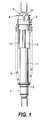
- FIG. 1 is a front view of a hydraulic shock absorber to which a spring force adjusting device according to this invention is applied.
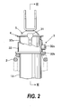
- FIG. 2 is a partially enlarged front view of an upper end portion of the hydraulic shock absorber of FIG. 1.
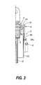
- FIG. 3 is a sectional view taken along the line III-III of FIG. 2.
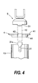
- FIG. 4 is an exploded view of the upper end portion of the hydraulic shock absorber.
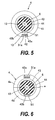
- FIG. 5 is a plan view showing a junction member of the hydraulic shock absorber.
- FIG. 6 is a plan view showing another example of the junction member.
- FIGS. 7A and 7B are views in which: FIG. 7A is an exploded view of another embodiment; and FIG. 7B is a side view of a part thereof.
- Hereinafter, an embodiment of this invention will be described with reference to the drawings. This embodiment describes a case where a spring force adjusting device of this invention is applied to a hydraulic shock absorber which supports a rear wheel of a motorcycle.
- The hydraulic shock absorber is provided with, as shown in FIG. 1, a
suspension spring 2 arranged on an outer periphery of a shock absorbermain body 1. The hydraulic shock absorber is further provided with acam mechanism 3 which adjusts a spring force of thesuspension spring 2. - The shock absorber
main body 1 includes acylinder 11 and arod 12 capable of axially extending from/ retracting into thecylinder 11. A lower end of thecylinder 11 is connected to a wheel (not shown) and an upper end of therod 12 is connected to a vehicle body (not shown). - A periphery of a portion of the
rod 12, which is exposed to the outside, is covered with atubular cover 13. Thecover 13 is connected to therod 12 so as to be detachable therefrom as described later. Thecover 13 has a diameter larger than that of thecylinder 11 and a length which is enough to entirely cover therod 12 even when therod 12 is operated fully to extend. When therod 12 retracts, thecover 13 overlaps therewith from the outside of thecylinder 11. - The
suspension spring 2 is supported at a lower end thereof by aspring seat 15 mounted on the outer periphery of thecylinder 11 and is supported at an upper end thereof by aspring seat 32b of thecam mechanism 3. Accordingly, by operating thecam mechanism 3 to vertically move thespring seat 32b, a compression amount of thesuspension spring 2 changes, thereby making it possible to adjust the spring force. - As shown in FIGS. 2 through 4, a
junction member 4 is placed on an upper portion of thecover 13 and atop cap 5 which is mounted to a tip of therod 12 is arranged on an upper portion of thejunction member 4. - The
cam mechanism 3 includes, as shown in FIGS. 2 and 3, acam barrel 32 introduced onto an outer periphery of thecover 13 so as to be rotatable, and astopper 31 fixed to an upper portion of thecover 13 by welding or the like. - A
cam surface 32a is formed on an upper end of thecam barrel 32. As shown in FIG. 2, thecam surface 32a includes three portions of different heights. An apical tip of thestopper 31 abuts on thecam surface 32a. - The
cam barrel 32 has, at a lower end thereof, thespring seat 32b formed in a flange-like fashion. Thespring seat 32b supports the upper end of thesuspension spring 2. - On the outer periphery of the
cam barrel 32, atool insertion portion 32c is provided. When a tool is inserted into thetool insertion portion 32c and thecam barrel 32 is rotated, an engagement position of thestopper 31 with respect to thecam surface 32a changes, thereby changing a height position of thecam barrel 32 with respect to thecover 13. - As a result, the upper end of the
suspension spring 2 is vertically moved, thereby changing the compression amount of thesuspension spring 2, making it possible to freely adjust the spring force of thesuspension spring 2 to be increased or reduced. - Next, a description will be made of a relationship among the
cover 13, thejunction member 4, and thetop cap 5. - FIG. 4 shows the
top cap 5, thejunction member 4, and thecover 13 in a state where they are separated. - As shown in FIGS. 2 and 3, the
top cap 5 is fixed to the tip of therod 12 by welding or the like. It should be noted that, being positioned inside thetop cap 5, acushioning rubber 6 is mounted to therod 12. When therod 12 retracts into thecylinder 11 to a maximum degree, thecushioning rubber 6 abuts on the upper end of thecylinder 11 to absorb an impact. - Between the
top cap 5 and thecover 13, the shallowtubular junction member 4 is sandwiched. Thejunction member 4 includes abottom portion 44 having, at a center thereof, a through-hole 43 through which thecushioning rubber 6 is passed and aflange portion 41 extending radially outwardly from a tube portion of thejunction member 4. - An outer diameter of the
top cap 5 is smaller than an inner diameter of thejunction member 4. A lower end of thetop cap 5 is allowed to abut on abottom portion 44 of thejunction member 4. Further, an inner diameter of thecover 13 is larger than an outer diameter of the tube portion of thejunction member 4. An upper end of thecover 13 is allowed to abut on theflange portion 41 of thejunction member 4. - The spring force of the
suspension spring 2 acts on thecover 13 through an intermediation of thecam mechanism 3, thereby allowing thejunction member 4 to be pushed upwards to abut on thetop cap 5. In this manner, thejunction member 4 is supported while being sandwiched between thecover 13 and thetop cap 5. - In order to remove the
junction member 4 from between thecover 13 and thetop cap 5 as described later, thejunction member 4 has, as shown in FIG. 5, a dividingslot 42 cut in a radial direction from theflange portion 41 to the through-hole 43 at the center thereof. A width of the dividingslot 42 is larger than the diameter of therod 12, so when removing thejunction member 4, therod 12 can pass through the dividingslot 42. - Further, the
cover 13, thejunction member 4, and thetop cap 5 are engaged with each other in a direction of rotation about an axis of those so as to be prevented from being rotated with respect to each other in the rotation direction. - With this construction, as shown in FIG. 4, the upper end of the
stopper 31 protrudes upwards from an end portion of thecover 13 to constitute anengagement portion 31a, and on a part of the lower end of thetop cap 5, anengagement portion 51 protruding downwards is formed. Theengagement portion 31a and theengagement portion 51 engage with the dividingslot 42 of thejunction member 4. In this case, theengagement portion 31a of thestopper 31 engages with anotch portion 42a on an outer peripheral side of the dividingslot 42, and theengagement portion 51 of thetop cap 5 engages with anotch portion 42b on an inner peripheral side of the dividingslot 42. - For replacement or the like of the
suspension spring 2, thecover 13, or thecam mechanism 3, removal of thejunction member 4 is made possible. - In order to remove the
junction member 4 from between thecover 13 and thetop cap 5, thecover 13 is pushed down while thesuspension spring 2 is compressed, thereby positioning thejunction member 4 below thecushioning rubber 6. - In this state, the
junction member 4 is moved toward the dividingslot 42 perpendicularly to the rod 12 (i.e., in a direction orthogonal to the rod 12). As a result, theengagement portion 31 a and theengagement portion 51 are detached from the dividingslot 42 and therod 12 passes through the dividingslot 42, thereby making it possible to remove thejunction member 4 from the hydraulic shock absorber. - When the
junction member 4 is removed, thecover 13 can move in an axial direction of the rod. In this case, the inner diameter of thecover 13 is larger than the outer diameter of thetop cap 5, so thecover 13 can be pulled out upwards along the outer side of thetop cap 5. After thecover 13 has been removed as described above, it is possible to replace thesuspension spring 2 or thecap mechanism 3. - The
junction member 4 can be formed in a so-called divided manner as shown in FIG. 6. - In FIG. 6, the
junction member 4 is divided into two by the diametrical cutting-plane line "a" passing an axis of thejunction member 4 and is composed of dividedmembers 4a and 4b. - The
notch portion 42a on the outer peripheral side, engaging with theengagement portion 31, is formed in theflange portion 41 of one dividedmember 4a. Thenotch portion 42b on the inner peripheral side, engaging with theengagement portion 51, is formed in thebottom portion 44 of the other divided member 4b. - With this construction, in a case of removing the
junction member 4 from between thecover 13 and thetop cap 5, thecover 13 is pressed down such that the upper end of thecover 13 is located below the lower surface of thejunction member 4, thereby making it possible to separate the dividedmembers 4a and 4b to the left and right to easily remove thejunction member 4. - Next, FIG. 7 shows an example including a swelling
portion 52 formed to protrude radially outwardly from the lower end of thetop cap 5, in place of theengagement portion 51 formed to protrude from the lower end of thetop cap 5. - The swelling
portion 52 is formed by allowing a part of the outer periphery of the lower end of thetop cap 5 to swell radially outwardly through press forming. The swellingportion 52 is formed such that a width thereof coincides with that of thenotch portion 42b on the inner peripheral side of the dividingslot 42. - The swelling
portion 52 is integrally formed through the press forming or the like in the above-mentioned manner, thereby making it possible to increase productivity and to reduce unit cost of the part. - In the hydraulic shock absorber formed as described above, a portion of the
rod 12, protruding from thecylinder 11, is entirely covered with thecover 13, so an outer periphery of therod 12 becomes resistant to adhesion of dirt or the like, thereby allowing therod 12 to smoothly extend/retract in any case. - The
cam mechanism 3 for thesuspension spring 2 is arranged on the outer side of thecover 13, so an operation of adjusting the spring force can be easily performed from the outside. Further, the cam mechanism is provided to the upper portion of the shock absorber. Therefore, as compared to a case where the cam mechanism is provided to the lower portion of the shock absorber, it is resistant to adhesion of dirt or the like and to damage. - In the case, for example, where it is required to replace the
suspension spring 2 or thecam mechanism 3 of the shock absorber, by removing thejunction member 4 from between thecover 13 and thetop cap 5, thecover 13 can be pulled out from above thetop cap 5, thereby making it possible to facilitate replacement and repair of thesuspension spring 2 or thecam mechanism 3. Thus, this construction provides excellent maintainability. - This invention is not limited to the embodiment described above, and it is needless to say that this invention includes various modifications and improvements within the scope of the technical principles of the invention.
Claims (6)
- A spring force adjusting device for a hydraulic shock absorber, comprising:a cylinder;a rod protruding from the cylinder so that the rod is free to extend and retract;a tube-shaped cover provided on an outside of the rod and having an inner diameter larger than an outer diameter of the cylinder;a suspension spring arranged on outer peripheries of the cylinder and the cover;a cam mechanism arranged on the outer periphery of the cover to adjust a spring force, the cam mechanism supporting one end of the suspension spring, being rotatable with respect to the cover, being engaged with the cover in an axial direction, and moving the one end of the suspension spring vertically according to a rotating position of the cam mechanism;a top cap mounted on a tip of the rod and having a diameter smaller than a diameter of the cover;a junction member sandwiched between the top cap and the cover and arranged so that the junction member can be attached and detached in a direction orthogonal to the rod; andmeans for preventing relative rotations of the top cap, the cover, and the junction member.
- The spring force adjusting device according to claim 1, wherein the cam mechanism comprises
a cam barrel, which is introduced onto the outer periphery of the cover, and has a cam surface and a spring seat which supports the one end of the suspension spring, the cam barrel being free to rotate, and
a stopper fixed to the cover and engaging with the cam surface. - The spring force adjusting device according to claim 1,
wherein the junction member is formed in a tubular shape having a shallow bottom portion provided with a through-hole at a center of the shallow bottom portion and a flange portion continuous with a periphery of the shallow bottom portion, wherein a lower end of the top cap abuts on the bottom portion, and an upper end of the cover abuts on the flange portion. - The spring force adjusting device according to claim 3,
wherein the means for preventing the relative rotations comprises notch portions provided on an inner peripheral side and an outer peripheral side of the junction member, a first engagement portion mounted to the cover to engage with the notch portion on the outer peripheral side, and a second engagement portion provided on the top cap to engage with the notch portion on the inner peripheral side. - The spring force adjusting device according to claim 4,
wherein the junction member is provided with an dividing slot cut in a radial direction from the flange portion to the through-hole, the dividing slot having a width larger than a diameter of the rod,
wherein the dividing slot serves as both the notch portion on the outer peripheral side, engaging with the first engagement portion, and the notch portion on the inner peripheral side, engaging with the second engagement portion. - The spring force adjusting device according to claim 4,
wherein the junction member is divided into two divided members by a diametrical cutting-plane line passing an axis of the junction member,
wherein one divided member of the two divided members is provided with a notch portion on an outer peripheral side of the junction member, engaging with the first engagement portion, and another divided member of two divided members is provided with a notch portion on an inner peripheral side of the junction member, engaging with the second engagement portion.
Applications Claiming Priority (2)
| Application Number | Priority Date | Filing Date | Title |
|---|---|---|---|
| JP2005271588A JP4683634B2 (en) | 2005-09-20 | 2005-09-20 | Spring force adjustment structure |
| JP2005344051A JP4535992B2 (en) | 2005-11-29 | 2005-11-29 | Spring force adjustment structure |
Publications (2)
| Publication Number | Publication Date |
|---|---|
| EP1764240A1 true EP1764240A1 (en) | 2007-03-21 |
| EP1764240B1 EP1764240B1 (en) | 2009-02-25 |
Family
ID=37467430
Family Applications (1)
| Application Number | Title | Priority Date | Filing Date |
|---|---|---|---|
| EP06019596A Ceased EP1764240B1 (en) | 2005-09-20 | 2006-09-19 | Adjustable hydraulic shock absorber |
Country Status (4)
| Country | Link |
|---|---|
| US (1) | US7896321B2 (en) |
| EP (1) | EP1764240B1 (en) |
| DE (1) | DE602006005298D1 (en) |
| TW (1) | TW200720572A (en) |
Cited By (1)
| Publication number | Priority date | Publication date | Assignee | Title |
|---|---|---|---|---|
| CN106286688A (en) * | 2015-05-29 | 2017-01-04 | 安顺市晶英科技研发有限责任公司 | A kind of automobile damper that can absorb lateral impact forces |
Families Citing this family (4)
| Publication number | Priority date | Publication date | Assignee | Title |
|---|---|---|---|---|
| DE102015217326A1 (en) * | 2015-09-10 | 2017-03-16 | Contitech Vibration Control Gmbh | Suspension strut |
| DE102016120094A1 (en) * | 2016-10-21 | 2018-04-26 | König + Neurath AG | spring device |
| US10570976B1 (en) * | 2017-03-14 | 2020-02-25 | Icon Vehicle Dynamics Llc | Reversible two setting preload spacer |
| US12515487B1 (en) | 2024-09-04 | 2026-01-06 | The Pullman Company Llc | Side loading top mount |
Citations (7)
| Publication number | Priority date | Publication date | Assignee | Title |
|---|---|---|---|---|
| DE958531C (en) * | 1954-08-27 | 1957-02-21 | Albert Dillenburger | Suspension strut adjustable by a hand lever, especially for motor vehicles |
| US4183509A (en) * | 1977-03-22 | 1980-01-15 | Honda Giken Kogyo Kabushiki Kaisha | Shock absorber for vehicle use |
| JPS56109937A (en) * | 1980-01-29 | 1981-08-31 | Kayaba Ind Co Ltd | Device for mounting spring in hydraulic shock absorber |
| JPH08210417A (en) * | 1995-02-07 | 1996-08-20 | Kayaba Ind Co Ltd | Shock absorber |
| JPH08210414A (en) * | 1995-01-31 | 1996-08-20 | Kayaba Ind Co Ltd | Shock absorber |
| JPH08270712A (en) * | 1995-03-31 | 1996-10-15 | Kayaba Ind Co Ltd | Rear wheel shock absorber spring load adjustment device |
| JPH10281207A (en) * | 1997-04-08 | 1998-10-23 | Kayaba Ind Co Ltd | Suspension spring adjustment device |
Family Cites Families (13)
| Publication number | Priority date | Publication date | Assignee | Title |
|---|---|---|---|---|
| FR995091A (en) * | 1949-07-20 | 1951-11-27 | Improvements to vehicle suspension systems | |
| US2756045A (en) * | 1953-06-02 | 1956-07-24 | Girling Ltd | Rear wheel suspensions for motorcycles |
| GB1267513A (en) * | 1968-04-26 | 1972-03-22 | Girling Ltd | Improvements in or relating to vehicle suspension units |
| GB1535771A (en) * | 1975-05-28 | 1978-12-13 | Girling Ltd | Vehicle suspension units |
| IT7953438V0 (en) * | 1978-09-06 | 1979-07-23 | Houdaille Lelaurain Sa | SUSPENSION DEVICE FOR VEHICLE WHEELS |
| US4418800A (en) * | 1980-06-12 | 1983-12-06 | Lucas Industries Limited | Motorcycle braking system having load sensitive pressure control valve |
| JPH0439134U (en) * | 1990-07-31 | 1992-04-02 | ||
| US5454550A (en) * | 1994-08-09 | 1995-10-03 | Christopherson Group | Dampening shock absorber |
| DE19521861C1 (en) * | 1995-06-16 | 1996-10-24 | Porsche Ag | Device for influencing coil spring characteristics of vehicle's wheel suspension |
| JPH10331896A (en) | 1997-06-02 | 1998-12-15 | Hks Co Ltd | Hydraulic shock absorber |
| JP3770435B2 (en) * | 1997-12-10 | 2006-04-26 | 本田技研工業株式会社 | Cylindrical shock absorber with cover |
| DE10101694C5 (en) * | 2001-01-15 | 2005-05-12 | Thyssenkrupp Automotive Ag | The vehicle chassis |
| US6827184B1 (en) * | 2003-07-18 | 2004-12-07 | Wei-Li Lin | Shock-absorbing device of an automobile |
-
2006
- 2006-09-08 TW TW095133142A patent/TW200720572A/en not_active IP Right Cessation
- 2006-09-19 EP EP06019596A patent/EP1764240B1/en not_active Ceased
- 2006-09-19 DE DE602006005298T patent/DE602006005298D1/en active Active
- 2006-09-19 US US11/523,086 patent/US7896321B2/en not_active Expired - Fee Related
Patent Citations (7)
| Publication number | Priority date | Publication date | Assignee | Title |
|---|---|---|---|---|
| DE958531C (en) * | 1954-08-27 | 1957-02-21 | Albert Dillenburger | Suspension strut adjustable by a hand lever, especially for motor vehicles |
| US4183509A (en) * | 1977-03-22 | 1980-01-15 | Honda Giken Kogyo Kabushiki Kaisha | Shock absorber for vehicle use |
| JPS56109937A (en) * | 1980-01-29 | 1981-08-31 | Kayaba Ind Co Ltd | Device for mounting spring in hydraulic shock absorber |
| JPH08210414A (en) * | 1995-01-31 | 1996-08-20 | Kayaba Ind Co Ltd | Shock absorber |
| JPH08210417A (en) * | 1995-02-07 | 1996-08-20 | Kayaba Ind Co Ltd | Shock absorber |
| JPH08270712A (en) * | 1995-03-31 | 1996-10-15 | Kayaba Ind Co Ltd | Rear wheel shock absorber spring load adjustment device |
| JPH10281207A (en) * | 1997-04-08 | 1998-10-23 | Kayaba Ind Co Ltd | Suspension spring adjustment device |
Cited By (1)
| Publication number | Priority date | Publication date | Assignee | Title |
|---|---|---|---|---|
| CN106286688A (en) * | 2015-05-29 | 2017-01-04 | 安顺市晶英科技研发有限责任公司 | A kind of automobile damper that can absorb lateral impact forces |
Also Published As
| Publication number | Publication date |
|---|---|
| TWI300458B (en) | 2008-09-01 |
| US20070062770A1 (en) | 2007-03-22 |
| US7896321B2 (en) | 2011-03-01 |
| TW200720572A (en) | 2007-06-01 |
| DE602006005298D1 (en) | 2009-04-09 |
| EP1764240B1 (en) | 2009-02-25 |
Similar Documents
| Publication | Publication Date | Title |
|---|---|---|
| US11364963B2 (en) | Bicycle seat post travel adjustment assembly | |
| US10974781B2 (en) | Bicycle seat post travel adjustment assembly | |
| EP2923919B1 (en) | Steering device | |
| US20040113408A1 (en) | Steering column apparatus | |
| EP1764240B1 (en) | Adjustable hydraulic shock absorber | |
| KR100510416B1 (en) | Energy absorbing tilting steering column for a vehicle | |
| JP3591284B2 (en) | Swing support device for steering column for tilt type steering device | |
| CN108528518B (en) | Steering device | |
| CN109641610A (en) | Steering column assembly | |
| CN109421786A (en) | Electric powered steering column device | |
| CN1659073A (en) | Steering column device for vehicle | |
| JP2008080946A (en) | Cap device | |
| CN102233906B (en) | Auto body part is to the bracing or strutting arrangement of other body portion | |
| CN1940338A (en) | Spring force adjusting device for a hydraulic shock absorber | |
| JP5181580B2 (en) | Steering device | |
| EP1795394A1 (en) | Retractable door mirror | |
| KR20170019743A (en) | Steering column for vehicle | |
| EP2228553B1 (en) | Device for the automatic correction of cable length in power window mechanisms | |
| JP4535992B2 (en) | Spring force adjustment structure | |
| JP5027716B2 (en) | Hydraulic shock absorber | |
| JP4932750B2 (en) | Adjuster structure | |
| JP4424022B2 (en) | Vehicle steering column device | |
| JP2000352436A (en) | Spring force adjusting device | |
| CN101470331B (en) | Camera support instrument | |
| JP4925307B2 (en) | Suspension device |
Legal Events
| Date | Code | Title | Description |
|---|---|---|---|
| PUAI | Public reference made under article 153(3) epc to a published international application that has entered the european phase |
Free format text: ORIGINAL CODE: 0009012 |
|
| AK | Designated contracting states |
Kind code of ref document: A1 Designated state(s): AT BE BG CH CY CZ DE DK EE ES FI FR GB GR HU IE IS IT LI LT LU LV MC NL PL PT RO SE SI SK TR |
|
| AX | Request for extension of the european patent |
Extension state: AL BA HR MK YU |
|
| 17P | Request for examination filed |
Effective date: 20070510 |
|
| AKX | Designation fees paid |
Designated state(s): DE IT |
|
| GRAP | Despatch of communication of intention to grant a patent |
Free format text: ORIGINAL CODE: EPIDOSNIGR1 |
|
| RTI1 | Title (correction) |
Free format text: ADJUSTABLE HYDRAULIC SHOCK ABSORBER |
|
| GRAS | Grant fee paid |
Free format text: ORIGINAL CODE: EPIDOSNIGR3 |
|
| GRAA | (expected) grant |
Free format text: ORIGINAL CODE: 0009210 |
|
| AK | Designated contracting states |
Kind code of ref document: B1 Designated state(s): DE IT |
|
| REF | Corresponds to: |
Ref document number: 602006005298 Country of ref document: DE Date of ref document: 20090409 Kind code of ref document: P |
|
| PLBE | No opposition filed within time limit |
Free format text: ORIGINAL CODE: 0009261 |
|
| STAA | Information on the status of an ep patent application or granted ep patent |
Free format text: STATUS: NO OPPOSITION FILED WITHIN TIME LIMIT |
|
| 26N | No opposition filed |
Effective date: 20091126 |
|
| REG | Reference to a national code |
Ref country code: DE Ref legal event code: R082 Ref document number: 602006005298 Country of ref document: DE Representative=s name: GRUENECKER PATENT- UND RECHTSANWAELTE PARTG MB, DE Ref country code: DE Ref legal event code: R081 Ref document number: 602006005298 Country of ref document: DE Owner name: KYB CORPORATION, JP Free format text: FORMER OWNER: KAYABA INDUSTRY CO., LTD., TOKYO, JP |
|
| PGFP | Annual fee paid to national office [announced via postgrant information from national office to epo] |
Ref country code: DE Payment date: 20200925 Year of fee payment: 15 |
|
| PGFP | Annual fee paid to national office [announced via postgrant information from national office to epo] |
Ref country code: IT Payment date: 20200922 Year of fee payment: 15 |
|
| REG | Reference to a national code |
Ref country code: DE Ref legal event code: R119 Ref document number: 602006005298 Country of ref document: DE |
|
| PG25 | Lapsed in a contracting state [announced via postgrant information from national office to epo] |
Ref country code: DE Free format text: LAPSE BECAUSE OF NON-PAYMENT OF DUE FEES Effective date: 20220401 |
|
| PG25 | Lapsed in a contracting state [announced via postgrant information from national office to epo] |
Ref country code: IT Free format text: LAPSE BECAUSE OF NON-PAYMENT OF DUE FEES Effective date: 20210919 |