EP1762512B1 - Dispositif de convoyage des capsules avec contenu pharmaceutique - Google Patents
Dispositif de convoyage des capsules avec contenu pharmaceutique Download PDFInfo
- Publication number
- EP1762512B1 EP1762512B1 EP05425632A EP05425632A EP1762512B1 EP 1762512 B1 EP1762512 B1 EP 1762512B1 EP 05425632 A EP05425632 A EP 05425632A EP 05425632 A EP05425632 A EP 05425632A EP 1762512 B1 EP1762512 B1 EP 1762512B1
- Authority
- EP
- European Patent Office
- Prior art keywords
- capsules
- capsule
- pharmaceutical product
- metering
- Prior art date
- Legal status (The legal status is an assumption and is not a legal conclusion. Google has not performed a legal analysis and makes no representation as to the accuracy of the status listed.)
- Not-in-force
Links
- 239000002775 capsule Substances 0.000 title claims description 52
- 239000000825 pharmaceutical preparation Substances 0.000 title claims description 16
- 229940127557 pharmaceutical product Drugs 0.000 title claims description 16
- 241000237983 Trochidae Species 0.000 description 3
- 230000004913 activation Effects 0.000 description 2
- 230000009849 deactivation Effects 0.000 description 1
- 239000013307 optical fiber Substances 0.000 description 1
- 238000005303 weighing Methods 0.000 description 1
Images


Classifications
-
- G—PHYSICS
- G01—MEASURING; TESTING
- G01G—WEIGHING
- G01G17/00—Apparatus for or methods of weighing material of special form or property
-
- B—PERFORMING OPERATIONS; TRANSPORTING
- B65—CONVEYING; PACKING; STORING; HANDLING THIN OR FILAMENTARY MATERIAL
- B65G—TRANSPORT OR STORAGE DEVICES, e.g. CONVEYORS FOR LOADING OR TIPPING, SHOP CONVEYOR SYSTEMS OR PNEUMATIC TUBE CONVEYORS
- B65G47/00—Article or material-handling devices associated with conveyors; Methods employing such devices
- B65G47/52—Devices for transferring articles or materials between conveyors i.e. discharging or feeding devices
- B65G47/525—Devices for transferring articles or materials between conveyors i.e. discharging or feeding devices using fluid jets
-
- B—PERFORMING OPERATIONS; TRANSPORTING
- B65—CONVEYING; PACKING; STORING; HANDLING THIN OR FILAMENTARY MATERIAL
- B65G—TRANSPORT OR STORAGE DEVICES, e.g. CONVEYORS FOR LOADING OR TIPPING, SHOP CONVEYOR SYSTEMS OR PNEUMATIC TUBE CONVEYORS
- B65G47/00—Article or material-handling devices associated with conveyors; Methods employing such devices
- B65G47/52—Devices for transferring articles or materials between conveyors i.e. discharging or feeding devices
- B65G47/64—Switching conveyors
- B65G47/641—Switching conveyors by a linear displacement of the switching conveyor
- B65G47/643—Switching conveyors by a linear displacement of the switching conveyor in a vertical plane
-
- B—PERFORMING OPERATIONS; TRANSPORTING
- B65—CONVEYING; PACKING; STORING; HANDLING THIN OR FILAMENTARY MATERIAL
- B65G—TRANSPORT OR STORAGE DEVICES, e.g. CONVEYORS FOR LOADING OR TIPPING, SHOP CONVEYOR SYSTEMS OR PNEUMATIC TUBE CONVEYORS
- B65G47/00—Article or material-handling devices associated with conveyors; Methods employing such devices
- B65G47/74—Feeding, transfer, or discharging devices of particular kinds or types
- B65G47/84—Star-shaped wheels or devices having endless travelling belts or chains, the wheels or devices being equipped with article-engaging elements
- B65G47/841—Devices having endless travelling belts or chains equipped with article-engaging elements
- B65G47/843—Devices having endless travelling belts or chains equipped with article-engaging elements the article-engaging elements being suction or magnetic means
Definitions
- the present invention relates to a device for conveying capsules containing at least one pharmaceutical product.
- a conveying device for feeding a succession of capsules, containing at least one pharmaceutical product, along a given path.
- the conveying device comprises a feed line normally defined by a pocket conveyor and a pneumatic conveyor connected to each other at a transfer station. As it travels through the transfer station, each capsule is fed through a detecting device for determining at least the weight of the pharmaceutical product inside the capsule.
- Document US-A-5750938 discloses a device for filling capsules with pharmaceutical products comprising two conveying drums designed as pocket conveyors for feeding the capsules along a given path and connected to one another at a transfer station.
- the device further comprises a weight sensor located at a given distance from the transfer station to determine the weight of the pharmaceutical product in each capsule.
- a device for conveying capsules containing at least one pharmaceutical product as claimed in the accompanying Claims.
- Number 1 in Figure 1 indicates as a whole a machine for filling capsules 2 with at least one pharmaceutical product.
- Each capsule 2 comprises a substantially cup-shaped bottom shell 3, and a top shell 4 for closing bottom shell 3 ( Figure 3 ).
- the empty capsules 2 are fed successively to an open-and-separate station 5, where the empty capsules 2 are opened, and the bottom shells 3 are picked up successively by a known conveying device 6, and are fed by device 6 along a given path T1 and through at least one filling station 7 comprising a number of known metering devices (not shown), each of which feeds a given quantity of a pharmaceutical product into a relative bottom shell 3.
- Path T1 extends between open-and-separate station 5 and a closing station 8, where each bottom shell 3 is closed with a relative top shell 4 fed from station 5 to station 8 along a path T2 so designed that bottom shell 3 and top shell 4 separated at station 5 arrive at station 8 in time with each other.
- Each full bottom shell 3 is closed in known manner inside a relative seat 9 on a closing wheel 10, which is mounted to rotate continuously (anticlockwise in Figure 1 ) about a respective substantially vertical longitudinal axis 11 perpendicular to the Figure 1 plane, and forms part of a device 12 for conveying the full capsules 2 from station 8 to a number of (in the example shown, three) output stations 13 described in detail below.
- Device 12 also comprises a first transfer wheel 14, which is mounted to rotate continuously (clockwise in Figures 1 and 2 ) about a respective longitudinal axis 15 parallel to axis 11, is connected to wheel 10 at a first transfer station 16, and is connected to a second transfer wheel 17 at a second transfer station 18.
- first transfer wheel 14 which is mounted to rotate continuously (clockwise in Figures 1 and 2 ) about a respective longitudinal axis 15 parallel to axis 11, is connected to wheel 10 at a first transfer station 16, and is connected to a second transfer wheel 17 at a second transfer station 18.
- Wheels 10, 14, 17 thus define a feed line for feeding the full capsules 2 along a given path P comprising an initial portion P1 extending between stations 8 and 16, an intermediate portion P2 extending between stations 16 and 18, and an end portion P3 extending between stations 18 and 13.
- transfer wheel 14 comprises a drum 19 bounded laterally by a substantially cylindrical surface 20 coaxial with axis 15, and has a number of substantially semicylindrical seats 21 formed on surface 20, parallel to axis 15, equally spaced about axis 15, and each for receiving and housing a respective full capsule 2.
- Each seat 21 is fed by wheel 14 through station 16 in time with a relative seat 9 on wheel 10, so that, as the two seats travel through station 16, the combined action of a pusher 22 and a counter-pusher 23 transfers the relative full capsule 2 from seat 9 to seat 21 in a substantially vertical direction 24 parallel to axes 11 and 15.
- Seats 21 normally communicate with a known pneumatic suction device (not shown) by means of respective conduits 25 formed through drum 19 and opening outwards at relative seats 21 to retain the full capsules 2 inside relative seats 21 along portion P2 of path P.
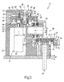
- Transfer wheel 17 comprises a supporting shaft 26, which is connected to a fixed frame 27, has a longitudinal axis 28 substantially parallel to direction 24, and supports a rotary drum 29 fitted in rotary and axially-fixed manner to shaft 26, with the interposition of two ball bearings 30, to rotate, with respect to shaft 26 and about axis 28, under the control of an actuating device 31.
- Device 31 comprises an electric motor 32, an output shaft 33 of which extends in direction 24, is parallel to shaft 26, and is fitted with a gear 34 meshing with a gear 35 fitted to drum 29.
- axes 15 and 28 are crosswise to each other, and pockets 38 are formed in the lateral surface of drum 29, parallel to direction 24, to maintain the same orientation of capsules 2 on both wheel 14 and wheel 17.
- Pockets 38 normally communicate with said pneumatic suction device (not shown) by means of a pneumatic circuit 39 comprising, for each pocket 38, a respective conduit 40 formed through drum 29 and opening outwards at relative pocket 38 to retain the relative full capsule 2 inside relative pocket 38 along portion P3 of path P.
- Conduits 40 also communicate pneumatically with an annular manifold 41 common to all of conduits 40 and formed in a sleeve 42, which is positioned facing surface 36, is fitted in sliding manner to supporting shaft 26, and is maintained contacting surface 36 by a spring 43 interposed between frame 27 and sleeve 42 to ensure fluidtight connection of conduits 40 and manifold 41.
- Manifold 41 in turn communicates pneumatically with a conduit 44, a first portion 45 of which is formed through sleeve 42 and connected in sliding and fluidtight manner to a second portion of conduit 44 defined by a bush 46, which is fixed inside frame 27, projects inside portion 45 and is connected to said pneumatic suction device (not shown).
- each pocket 38 is fed selectively by wheel 17 (anticlockwise in Figures 2 and 3 ) to one of the three output stations 13 (hereinafter indicated 13a, 13b, 13c) arranged successively in that order about axis 28 and along portion P3 of path P.
- Each station 13a, 13b, 13c has a compressed-air nozzle 53, which extends through sleeve 42, parallel to direction 24, projects at one end inside manifold 41 and at the other end inside frame 27, is fitted in sliding and fluidtight manner to frame 27, and has an outlet hole 54 which communicates pneumatically with conduits 40 of pockets 38 as they are fed through station 13a, 13b, 13c.
- nozzle 53 of station 13a is activated selectively, as a function of a signal from sensor 48, to unload from relative pockets 38 any full capsules 2 of a weight differing from a given reference value; nozzle 53 of station 13b is activated selectively to periodically feed full capsules 2 to a known weighing device (not shown) to feedback control correct operation of sensor 48; and nozzle 53 of station 13c is activated at all times to unload from relative pockets 38 the full capsules 2 fed through stations 13a and 13b and of a weight substantially equal to said reference value.
Landscapes
- Engineering & Computer Science (AREA)
- Mechanical Engineering (AREA)
- Physics & Mathematics (AREA)
- General Physics & Mathematics (AREA)
- Basic Packing Technique (AREA)
- Medical Preparation Storing Or Oral Administration Devices (AREA)
- Specific Conveyance Elements (AREA)
Claims (10)
- Dispositif destiné au transport de capsules (2) contenant au moins un produit pharmaceutique, le dispositif comprenant au moins deux dispositifs de transport (10, 14, 17) pour fournir lesdites capsules (2) le long d'un chemin donné (P) ; un poste de transfert (18) reliant lesdits dispositifs de transport (10, 14, 17) l'un à l'autre ; et un dispositif de détection (47) situé au niveau dudit poste de transfert (18) pour déterminer au moins le poids du produit pharmaceutique dans chaque capsule (2), le dispositif de détection (47) comprenant au moins un capteur (48) présentant au moins un canal d'alimentation (49) emprunté successivement par lesdites capsules (2) lorsqu'elles sont transférées du premier au second dispositif de transport à poches (14, 17) ; un desdits dispositifs de transport (10, 14, 17) étant défini par un premier dispositif de transport à poches (14) présentant un nombre de premières poches (21), chacune destinée à loger une capsule (2), et l'autre dispositif de transport étant défini par un second dispositif de transport à poches (17) présentant un nombre de secondes poches (38), chacune destinée à loger une capsule (2) ; des moyens de transfert (50, 51) étant prévus pour transférer une capsule (2) de la première poche (21) à la seconde poche (38) sans changement d'orientation de la capsule (2).
- Dispositif selon la revendication 1, dans lequel ledit chemin (P) comprend une partie sensiblement verticale (49) s'étendant à travers ledit poste de transfert (18).
- Dispositif selon la revendication 1 ou 2, comprenant également des moyens d'actionnement (31) pour faire avancer chaque seconde poche (38) de manière synchronisée avec une dite capsule relative (2) sortant dudit canal d'alimentation (49).
- Dispositif selon l'une quelconque des revendications précédentes, dans lequel ledit premier et ledit second dispositif de transport à poches (14, 17) sont deux roues de transfert montées de manière à tourner autour d'axes longitudinaux respectifs (15, 28).
- Dispositif selon la revendication 4, dans lequel lesdits axes (15, 28) sont sensiblement parallèles l'un à l'autre.
- Dispositif selon la revendication 4, dans lequel lesdits axes (15, 28) sont sensiblement transversaux l'un par rapport à l'autre.
- Dispositif selon l'une quelconque des revendications précédentes, comprenant également une roue de fermeture (10) destinée à fermer lesdites capsules (2) et à transférer les capsules (2) successivement vers ledit premier dispositif de transport à poches ((14).
- Machine destinée au remplissage de capsules (2) avec au moins un produit pharmaceutique, la machine comprenant un dispositif de transport selon l'une quelconque des revendications précédentes.
- Machine selon la revendication 8, comprenant également un dispositif de mesure destiné à mesurer le produit pharmaceutique dans les capsules (2) ; et des moyens de commande logique pour la commande à rétroaction du dispositif de mesure en fonction d'un signal provenant dudit dispositif de détection (47).
- Machine selon la revendication 8 ou 9, comprenant également un nombre de dispositifs de mesure destinés à mesurer le produit pharmaceutique dans les capsules (2) ; chaque seconde poche (38) étant interconnectée et synchronisée avec au moins un dispositif de mesure.
Priority Applications (5)
| Application Number | Priority Date | Filing Date | Title |
|---|---|---|---|
| EP05425632A EP1762512B1 (fr) | 2005-09-09 | 2005-09-09 | Dispositif de convoyage des capsules avec contenu pharmaceutique |
| DE602005008599T DE602005008599D1 (de) | 2005-09-09 | 2005-09-09 | Vorrichtung zum Fördern von Kapseln mit pharmazeutischem Inhalt |
| JP2006243966A JP2007076921A (ja) | 2005-09-09 | 2006-09-08 | 少なくとも一つの薬剤を収容するカプセルの搬送装置 |
| CNA2006101541147A CN1939250A (zh) | 2005-09-09 | 2006-09-08 | 传送包含至少一种药物产品的胶囊的装置 |
| US11/519,424 US7328559B2 (en) | 2005-09-09 | 2006-09-11 | Device for conveying capsules containing at least one pharmaceutical product |
Applications Claiming Priority (1)
| Application Number | Priority Date | Filing Date | Title |
|---|---|---|---|
| EP05425632A EP1762512B1 (fr) | 2005-09-09 | 2005-09-09 | Dispositif de convoyage des capsules avec contenu pharmaceutique |
Publications (2)
| Publication Number | Publication Date |
|---|---|
| EP1762512A1 EP1762512A1 (fr) | 2007-03-14 |
| EP1762512B1 true EP1762512B1 (fr) | 2008-07-30 |
Family
ID=35614170
Family Applications (1)
| Application Number | Title | Priority Date | Filing Date |
|---|---|---|---|
| EP05425632A Not-in-force EP1762512B1 (fr) | 2005-09-09 | 2005-09-09 | Dispositif de convoyage des capsules avec contenu pharmaceutique |
Country Status (5)
| Country | Link |
|---|---|
| US (1) | US7328559B2 (fr) |
| EP (1) | EP1762512B1 (fr) |
| JP (1) | JP2007076921A (fr) |
| CN (1) | CN1939250A (fr) |
| DE (1) | DE602005008599D1 (fr) |
Families Citing this family (15)
| Publication number | Priority date | Publication date | Assignee | Title |
|---|---|---|---|---|
| US7304750B2 (en) * | 1999-12-17 | 2007-12-04 | Nektar Therapeutics | Systems and methods for non-destructive mass sensing |
| ITBO20040577A1 (it) * | 2004-09-17 | 2004-12-17 | Mg 2 Srl | Metodo e ruota per il trasferimento di coperchi di capsule in una macchina per il riempimento di capsule con almeno un prodotto farmaceutico |
| DE102005057393A1 (de) * | 2005-11-30 | 2007-05-31 | Robert Bosch Gmbh | Wiegevorrichtung einer Verpackungsmaschine |
| EP2083787B1 (fr) * | 2006-10-24 | 2012-12-12 | Capsugel Belgium NV | Chaîne de tranfert |
| IT1397610B1 (it) * | 2009-12-22 | 2013-01-18 | Mg 2 Srl | Macchina rotativa intermittente per il riempimento di capsule con prodotti farmaceutici. |
| WO2012021899A2 (fr) * | 2010-08-13 | 2012-02-16 | Intellimedicine, Inc. | Système et procédé pour la production de produits pharmaceutiques personnalisés |
| IT1402461B1 (it) * | 2010-11-03 | 2013-09-13 | Mg 2 Srl | Metodo e macchina per il riempimento di capsule o simili con almeno due prodotti, in particolare prodotti farmaceutici in granuli |
| ITBO20120068A1 (it) * | 2012-02-15 | 2013-08-16 | Ima Ind Srl | Macchina per la formazione di capsule monouso per bevande |
| DE102012016653A1 (de) * | 2012-08-24 | 2014-02-27 | Haver & Boecker Ohg | Vorrichtung und Verfahren zurn Betreiben einer Vorrichtung |
| WO2014087133A1 (fr) * | 2012-12-05 | 2014-06-12 | Molins Plc | Dispositif de pesée |
| CN104995094B (zh) * | 2013-03-06 | 2016-12-28 | 吉玛股份公司 | 用于制造一次性饮料囊的饮料囊机 |
| ITBO20130178A1 (it) * | 2013-04-19 | 2014-10-20 | Mg 2 Srl | Macchina rotativa continua per il riempimento di capsule con prodotti farmaceutici |
| IT201700018745A1 (it) | 2017-02-20 | 2018-08-20 | Gd Spa | Metodo e dispositivo per controllare la quantità di liquido contenuta in una cartuccia per un dispositivo generatore di aerosol |
| IT201700123930A1 (it) * | 2017-10-31 | 2019-05-01 | Ima Spa | Macchina riempitrice. |
| KR20220004185A (ko) * | 2019-05-13 | 2022-01-11 | 아이.엠.에이. 인듀스트리아 마친 오토메티크 에스.피.에이. | 자동 가공 기계용 질량 측정 장치 및 질량 측정 방법 |
Family Cites Families (9)
| Publication number | Priority date | Publication date | Assignee | Title |
|---|---|---|---|---|
| JPS5524381A (en) * | 1978-08-10 | 1980-02-21 | Hakko Denki Seisakusho Kk | Ceramic heater |
| US4682683A (en) * | 1978-09-01 | 1987-07-28 | R. W. Hartnett Company | Method and apparatus for removing improperly oriented articles from a moving article |
| AU534332B2 (en) * | 1979-04-27 | 1984-01-19 | Nippon Elanco K.K. | Capsule orientation |
| JPH0725421B2 (ja) * | 1983-03-04 | 1995-03-22 | 武田薬品工業株式会社 | 固形製剤の検査装置 |
| IT1264247B1 (it) * | 1993-10-22 | 1996-09-23 | Mg 2 Spa | Metodo per la determinazione del peso di prodotti farmaceutici e macchina per la dosatura di prodotti farmaceutici utilizzante |
| IT1300001B1 (it) * | 1998-05-04 | 2000-04-04 | Mg 2 Spa | Gruppo orientatore di coperchi o fondelli per capsule medicinali ed unita' alimentatrice ed orientatrice relativa a tale gruppo. |
| JP4785245B2 (ja) * | 2000-08-02 | 2011-10-05 | 株式会社ヒューブレイン | 微小物体検査装置 |
| AU2003246206A1 (en) * | 2002-07-05 | 2004-01-23 | Shionogi Qualicaps Co., Ltd. | Capsule-filling and -sealing apparatus |
| ITFI20030012A1 (it) * | 2003-01-15 | 2004-07-16 | Giuseppe Piemontese | Un procedimento di sigillatura di capsule ed un'attrezzatura |
-
2005
- 2005-09-09 DE DE602005008599T patent/DE602005008599D1/de active Active
- 2005-09-09 EP EP05425632A patent/EP1762512B1/fr not_active Not-in-force
-
2006
- 2006-09-08 CN CNA2006101541147A patent/CN1939250A/zh active Pending
- 2006-09-08 JP JP2006243966A patent/JP2007076921A/ja active Pending
- 2006-09-11 US US11/519,424 patent/US7328559B2/en not_active Expired - Fee Related
Also Published As
| Publication number | Publication date |
|---|---|
| US7328559B2 (en) | 2008-02-12 |
| US20070062164A1 (en) | 2007-03-22 |
| JP2007076921A (ja) | 2007-03-29 |
| DE602005008599D1 (de) | 2008-09-11 |
| EP1762512A1 (fr) | 2007-03-14 |
| CN1939250A (zh) | 2007-04-04 |
Similar Documents
| Publication | Publication Date | Title |
|---|---|---|
| EP1762512B1 (fr) | Dispositif de convoyage des capsules avec contenu pharmaceutique | |
| US7726101B2 (en) | Method and machine for filling capsules or similar with at least one product, in particular a pharmaceutical product in microtablets | |
| EP2174637B1 (fr) | Machine pour le remplissage de capsules avec un produit | |
| EP1857087B1 (fr) | Remplisseuse pour remplir des conteneurs avec au moins un produit granuleux | |
| JPH06345046A (ja) | 特にチョコレート等の食品用の包装方法及び包装機 | |
| EP1522302B1 (fr) | Unité d'alimentation de formes médicamenteuses solides dans une ligne de transport d'une machine destinée au remplissage de gélules | |
| EP1884227B1 (fr) | Méthode et dispositif pour faire avancer des articles dans une machine de remplissage de capsules pharmaceutiques | |
| US5743069A (en) | Metering machine | |
| US6595249B2 (en) | Machine for filling capsules with a powdered product | |
| US5400574A (en) | System for feeding and packing products in pillow pack wrappings | |
| US6585013B2 (en) | Machine for filling capsules with at least one product | |
| US5301792A (en) | Unit for transferring food products, such as chocolates, between production machines | |
| US20060059867A1 (en) | Method and wheel for transferring top shells of capsules on a machine for filling capsules with at least one pharmaceutical product | |
| US20070079576A1 (en) | Method and unit for transferring a product on an intermittent packing machine | |
| US7357275B2 (en) | Unit for feeding capsules onto a capsule filling machine | |
| EP0878397A1 (fr) | Machine d'emballage pour cigarettes avec des lignes d'enveloppement multiples | |
| US7073655B2 (en) | Device for processing substantially parallelepiped -shaped products | |
| US5718324A (en) | Continuous cigarette manufacturing machine | |
| US5664584A (en) | Device for laterally transferring an orderly succession of smoking items |
Legal Events
| Date | Code | Title | Description |
|---|---|---|---|
| PUAI | Public reference made under article 153(3) epc to a published international application that has entered the european phase |
Free format text: ORIGINAL CODE: 0009012 |
|
| AK | Designated contracting states |
Kind code of ref document: A1 Designated state(s): AT BE BG CH CY CZ DE DK EE ES FI FR GB GR HU IE IS IT LI LT LU LV MC NL PL PT RO SE SI SK TR |
|
| AX | Request for extension of the european patent |
Extension state: AL BA HR MK YU |
|
| 17P | Request for examination filed |
Effective date: 20070913 |
|
| 17Q | First examination report despatched |
Effective date: 20071022 |
|
| AKX | Designation fees paid |
Designated state(s): DE IT |
|
| GRAP | Despatch of communication of intention to grant a patent |
Free format text: ORIGINAL CODE: EPIDOSNIGR1 |
|
| GRAS | Grant fee paid |
Free format text: ORIGINAL CODE: EPIDOSNIGR3 |
|
| GRAA | (expected) grant |
Free format text: ORIGINAL CODE: 0009210 |
|
| AK | Designated contracting states |
Kind code of ref document: B1 Designated state(s): DE IT |
|
| REF | Corresponds to: |
Ref document number: 602005008599 Country of ref document: DE Date of ref document: 20080911 Kind code of ref document: P |
|
| PLBE | No opposition filed within time limit |
Free format text: ORIGINAL CODE: 0009261 |
|
| STAA | Information on the status of an ep patent application or granted ep patent |
Free format text: STATUS: NO OPPOSITION FILED WITHIN TIME LIMIT |
|
| 26N | No opposition filed |
Effective date: 20090506 |
|
| PGFP | Annual fee paid to national office [announced via postgrant information from national office to epo] |
Ref country code: DE Payment date: 20101129 Year of fee payment: 6 |
|
| PGFP | Annual fee paid to national office [announced via postgrant information from national office to epo] |
Ref country code: IT Payment date: 20100923 Year of fee payment: 6 |
|
| PG25 | Lapsed in a contracting state [announced via postgrant information from national office to epo] |
Ref country code: IT Free format text: LAPSE BECAUSE OF NON-PAYMENT OF DUE FEES Effective date: 20110909 |
|
| REG | Reference to a national code |
Ref country code: DE Ref legal event code: R119 Ref document number: 602005008599 Country of ref document: DE Effective date: 20120403 |
|
| PG25 | Lapsed in a contracting state [announced via postgrant information from national office to epo] |
Ref country code: DE Free format text: LAPSE BECAUSE OF NON-PAYMENT OF DUE FEES Effective date: 20120403 |