EP1760451A1 - Method and system for road surface friction coefficient estimation - Google Patents
Method and system for road surface friction coefficient estimation Download PDFInfo
- Publication number
- EP1760451A1 EP1760451A1 EP05108015A EP05108015A EP1760451A1 EP 1760451 A1 EP1760451 A1 EP 1760451A1 EP 05108015 A EP05108015 A EP 05108015A EP 05108015 A EP05108015 A EP 05108015A EP 1760451 A1 EP1760451 A1 EP 1760451A1
- Authority
- EP
- European Patent Office
- Prior art keywords
- road surface
- surface friction
- friction coefficient
- algorithm
- vehicle
- Prior art date
- Legal status (The legal status is an assumption and is not a legal conclusion. Google has not performed a legal analysis and makes no representation as to the accuracy of the status listed.)
- Withdrawn
Links
- 238000000034 method Methods 0.000 title claims abstract description 27
- 238000004422 calculation algorithm Methods 0.000 claims abstract description 58
- 238000004590 computer program Methods 0.000 claims abstract description 12
- 230000003068 static effect Effects 0.000 claims abstract description 8
- 230000001052 transient effect Effects 0.000 claims abstract description 6
- 230000001133 acceleration Effects 0.000 claims description 12
- 230000001419 dependent effect Effects 0.000 claims description 2
- 238000004364 calculation method Methods 0.000 description 14
- 230000008901 benefit Effects 0.000 description 11
- 230000004044 response Effects 0.000 description 5
- 238000010586 diagram Methods 0.000 description 4
- 230000008859 change Effects 0.000 description 3
- 230000006978 adaptation Effects 0.000 description 2
- 238000012986 modification Methods 0.000 description 2
- 230000004048 modification Effects 0.000 description 2
- 230000007704 transition Effects 0.000 description 2
- 239000010426 asphalt Substances 0.000 description 1
- 238000013500 data storage Methods 0.000 description 1
- 238000001514 detection method Methods 0.000 description 1
- 230000005284 excitation Effects 0.000 description 1
- 230000005484 gravity Effects 0.000 description 1
- 230000010354 integration Effects 0.000 description 1
- 230000000452 restraining effect Effects 0.000 description 1
- 238000000926 separation method Methods 0.000 description 1
Images

Classifications
-
- B—PERFORMING OPERATIONS; TRANSPORTING
- B60—VEHICLES IN GENERAL
- B60T—VEHICLE BRAKE CONTROL SYSTEMS OR PARTS THEREOF; BRAKE CONTROL SYSTEMS OR PARTS THEREOF, IN GENERAL; ARRANGEMENT OF BRAKING ELEMENTS ON VEHICLES IN GENERAL; PORTABLE DEVICES FOR PREVENTING UNWANTED MOVEMENT OF VEHICLES; VEHICLE MODIFICATIONS TO FACILITATE COOLING OF BRAKES
- B60T8/00—Arrangements for adjusting wheel-braking force to meet varying vehicular or ground-surface conditions, e.g. limiting or varying distribution of braking force
- B60T8/17—Using electrical or electronic regulation means to control braking
- B60T8/172—Determining control parameters used in the regulation, e.g. by calculations involving measured or detected parameters
-
- B—PERFORMING OPERATIONS; TRANSPORTING
- B60—VEHICLES IN GENERAL
- B60T—VEHICLE BRAKE CONTROL SYSTEMS OR PARTS THEREOF; BRAKE CONTROL SYSTEMS OR PARTS THEREOF, IN GENERAL; ARRANGEMENT OF BRAKING ELEMENTS ON VEHICLES IN GENERAL; PORTABLE DEVICES FOR PREVENTING UNWANTED MOVEMENT OF VEHICLES; VEHICLE MODIFICATIONS TO FACILITATE COOLING OF BRAKES
- B60T2210/00—Detection or estimation of road or environment conditions; Detection or estimation of road shapes
- B60T2210/10—Detection or estimation of road conditions
- B60T2210/12—Friction
-
- B—PERFORMING OPERATIONS; TRANSPORTING
- B60—VEHICLES IN GENERAL
- B60T—VEHICLE BRAKE CONTROL SYSTEMS OR PARTS THEREOF; BRAKE CONTROL SYSTEMS OR PARTS THEREOF, IN GENERAL; ARRANGEMENT OF BRAKING ELEMENTS ON VEHICLES IN GENERAL; PORTABLE DEVICES FOR PREVENTING UNWANTED MOVEMENT OF VEHICLES; VEHICLE MODIFICATIONS TO FACILITATE COOLING OF BRAKES
- B60T2270/00—Further aspects of brake control systems not otherwise provided for
- B60T2270/86—Optimizing braking by using ESP vehicle or tyre model
Definitions
- the present invention relates to active chassis systems and a method, a system and a computer program product for road to wheel friction estimation (RFE). More specifically, the present invention relates to a method, a system and computer program product for estimating, with especially high accuracy, the road surface friction coefficient ( ⁇ ).
- RFE road to wheel friction estimation
- While driving a vehicle such as a passenger car, the driver may come across different road surfaces, such as asphalt, gravel road, dry, wet, ice, snow, and so on. These and other types of road surfaces are characterized by different road friction coefficients ( ⁇ ), affecting tire grip and vehicle stability.
- the vehicle can be operated in a fashion that permits it to, at any time, quickly respond to various road surface conditions.
- a problem with this model is that it is incapable of addressing sudden changes of road surface conditions.
- One model includes a preview camera which recognizes road conditions ahead of the vehicle and various infrastructure information.
- An object of the present invention is to provide a method, a system and a computer program product for estimating, with high accuracy, the momentary road surface friction coefficient ( ⁇ ).
- This object is basically achieved through use features from the stable, continuous calculation capability of the algorithm for calculating a momentary road surface friction coefficient ( ⁇ ) based on a vehicle dynamics model in combination with features from the fast, accurate response of a self aligning torque based algorithm.
- a method for estimating road surface friction between a road surface and a tire of a vehicle comprising the steps of: continuously estimating a road surface friction coefficient ( ⁇ ), using an algorithm based on a dynamic model of the vehicle, determining a road surface friction coefficient range based on specific transient or static vehicle driving parameters, and reinitiating said algorithm so that the estimated road surface friction coefficient ( ⁇ ) is adapted to said determined road surface friction coefficient range.
- An advantage of the solution according to the present invention is that it has a larger operation range and covers a wider span of application. The performance of those active chassis systems in which the solution is implemented is thus increased.
- Another advantage is that no compromises are necessary between fast response to ⁇ transitions and stable behavior in steady ⁇ conditions of the estimated road surface friction coefficient.
- said algorithm is reinitiated so that said road surface friction coefficient ( ⁇ ) is adapted downwards.
- said algorithm is reinitiated so that said road surface friction coefficient ( ⁇ ) is adapted to fall within said road surface friction coefficient range.
- An advantage of the latter embodiments is that no compromise is necessary between fast response to ⁇ transitions and stable behavior in steady ⁇ conditions of the estimated road surface friction coefficient.
- the step of determining a road surface friction coefficient range further comprises the steps of: measuring a self aligning torque, and calculating road surface friction coefficient range based on said measured self aligning torque.
- the step of determining a road surface friction coefficient range further comprises the steps of: measuring at least one of a lateral and longitudinal vehicle acceleration, and calculating said road surface friction coefficient range based on said measured vehicle acceleration.
- An advantage of the present invention is that the upper and lower limits of ⁇ -estimates can be set separately by algorithms independent of each other. This means that each algorithm can be tuned independently for maximum performance.
- a forget function may widen the calculation span for the algorithm for calculating said road surface friction coefficient ( ⁇ ).
- values of said specific vehicle driving parameters are dependent on at least one of internally derived circumstances and externally derived circumstances.
- a system for estimating road surface friction between a road surface and a tire of a vehicle comprising: means for continuously estimating a road surface friction coefficient ( ⁇ ), using an algorithm based on a dynamic model of the vehicle, means for determining a road surface friction coefficient range based on specific transient or static vehicle driving parameters, and means for reinitiating said algorithm so that the estimated road surface friction coefficient ( ⁇ ) is adapted to said determined road surface friction coefficient range.
- it further comprises: means for reinitiating said algorithm so that said road surface friction coefficient ( ⁇ ) is adapted downwards, if the continuously estimated road surface friction coefficient ( ⁇ ) is higher than an upper boundary value of said road surface friction coefficient range.
- it further comprises: means for reinitiating said algorithm so that said road surface friction coefficient ( ⁇ ) is adapted upwards, if the estimated road surface friction coefficient ( ⁇ ) is lower than a lower boundary value of said road surface friction coefficient range.
- it further comprises: means for reinitiating said algorithm so that said road surface friction coefficient ( ⁇ ) is adapted to fall within said road surface friction coefficient range.
- the system further comprises: means for measuring a self aligning torque, and means for calculating road surface friction coefficient range based on said measured self aligning torque.
- the system further comprises: means for measuring a self aligning torque, and means for calculating road surface friction coefficient range based on said measured self aligning torque.
- a computer program product for estimating road surface friction between a road surface and a tire of a vehicle, said computer software comprising code for execution of the steps according to one of said methods.
- said computer program product is stored on a computer readable medium.
- said computer program product may be stored on a computer readable medium such as an on-board electronic control unit (ECU).
- ECU electronice control unit
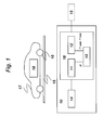
- Fig 1 is a schematic illustration of a system 10 for estimating road surface friction between a road surface 15 and a tire 16 of a vehicle 17, according to one embodiment of the present invention, said system 10 comprising means 11 for continuously estimating a road surface friction coefficient ( ⁇ ), using an algorithm based on a dynamic model of the vehicle, means 12 for determining a road friction coefficient range based on specific transient or static driving conditions, means 13 for reinitiating said algorithm so that the estimated road surface friction coefficient ( ⁇ ) is adapted to said range, and sensor means 14.
- the means 11-13 is stored on a computer readable medium 18, such as an on-board electronic control unit (ECU), which is a control unit for a component or device of the vehicle 17, e.g., the brakes or the motor.
- ECU electronice control unit
- said computer readable medium, or ECU comprises means corresponding to common computer means and data storage means.
- the design of the algorithm described according to the present invention is to continuously use said algorithm of the means 11 for calculating a momentary road surface friction coefficient ( ⁇ ) based on a vehicle dynamics model, but also to use additional support algorithms of the means 12 for determining a road friction coefficient range to speed up the detection of change in ⁇ .
- the reference vehicle dynamics model that is used in the calculation of the means 11 is based on a bicycle model. However, any other vehicle model could be used within the present invention.
- the output from it is the estimated side slip angle and lateral velocity of front axle. However, it could output yaw rate/yaw error as well. It also incorporates estimations for, e.g., dynamic load shift, lateral force, and yaw error.
- the means 11 can use calculations of lateral and longitudinal load shift.
- dynamic load shift is a vital part of the algorithm strategy within the present invention. It allows for separation of left and right calculation of road friction estimation. The benefit of this is that the outer wheel will always show larger forces, improving the signal resolution. Besides that, the outer wheel is also the wheel that has the most influence on cornering ability.
- the load shift block is designed to make a correction of the forces acting on the wheels as the vehicle corners, accelerates or brakes.
- the lower and upper limit values for the momentary road surface friction coefficient ( ⁇ ) calculated by the means 11 are calculated through different support algorithms of the means 12, not necessarily working at the same time as the algorithm of the means 11 for calculating a momentary road surface friction coefficient ( ⁇ ) based on a vehicle dynamics model.
- One of these support algorithms of the means 12 is a self aligning torque algorithm. This works during almost the same driving conditions as the algorithm of the means 11 for calculating a momentary road surface friction coefficient ( ⁇ ) based on a vehicle dynamics model, e.g. when vehicle speed is above a threshold value and the steering wheel angle is larger than a threshold value.
- the algorithm of the means 12 first calculates a road surface friction coefficient ( ⁇ sat ) based on a self aligning torque.
- the self aligning torque is also influenced by other parameters. These are steering system friction (T fr ), drive torque (T d ) , toe (T toe ) and camber angle (T camber ) variation, caster, static toe and camber (T offset ).
- the steering wheel torque sensor and the pressure sensors in the HPS system are filtered and centered. This has integrated functionality for correct operation of the self aligning torque calculation.
- the self aligning torque based road surface friction coefficient ( ⁇ sat ) is obtained from a look-up table depending upon the self aligning torque and a slide-angle of the front wheels.
- the vehicle lateral acceleration can be replaced by longitudinal acceleration or the vectrial sum (square root of sum of squares) of longitudinal and lateral acceleration.
- Zero tire grip margin means full usage of road surface ⁇ .
- the estimating accuracy is estimated to be high and the means 12 sets an error range between the lower and upper limit values around the self aligning torque based road surface friction coefficient ( ⁇ sat ) narrow.
- the means 12 sets the error range wide. This error range is provided to the means 13 so that the means 13 integrates the road surface friction coefficient ( ⁇ ) calculated by the means 11 with the error range set by the means 12 and reinitiates the calculation of the road surface friction coefficient ( ⁇ ) based on a vehicle dynamics model from a lower or upper limit value of said error range.
- the means 12 can set lower and upper limit values for the road surface friction coefficient ( ⁇ ) individually according to the tire grip margin, instead of setting lower and upper limit values in pair in the form of error range.
- a forget function is applied to the lower or upper limit value to gradually widens the calculation span for the algorithm for calculating a momentary road surface friction coefficient ( ⁇ ) based on a vehicle dynamics model.
- the basic idea of the invention is to use the continuous calculation capability of the algorithm for calculating a momentary road surface friction coefficient ( ⁇ ) based on a vehicle dynamics model in combination with the fast response of a self aligning torque based algorithm.
- Said lower and upper limit values described earlier are used to rapidly force the algorithm for calculating a momentary road surface friction coefficient ( ⁇ ) based on a vehicle dynamics model to a new value, resetting it and allowing it to calculate from this new point.
- Fig 2 is a schematic diagram showing operation of the system 10 according to the first embodiment of the present invention. It is assumed that at time points 20 and 21, the actual road surface condition suddenly change. Although the road surface friction coefficient ( ⁇ ) calculated by the means 11 is unable to respond to such sudden changes of road surface conditions, it is adapted downwards at the time point 20 by means of an upper limit value of the error range set by the means 12 depending upon the self aligning torque based algorithm. Thereafter, the means 11 continues calculation of the road surface friction coefficient ( ⁇ ) from the upper limit value.
- the road surface friction coefficient ( ⁇ ) is adapted upwards by means of a lower limit value of the error range set by the means 12 and then the calculation of the road surface friction coefficient ( ⁇ ) is reinitiated from the lower limit value.
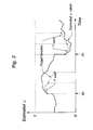
- Fig 3 is a schematic diagram showing operation of the system 10 according to the second embodiment of the present invention. It is assumed that at time points 30 and 31, the actual road surface conditions suddenly change.
- the road surface friction coefficient ( ⁇ ) calculated by the means 11 is adapted downwards at the time point 30 by means of an upper limit value calculated by the means 12 depending upon the self aligning torque based algorithm.
- the road surface friction coefficient ( ⁇ ) is adapted upwards by means of a lower limit value calculated by the means 12 depending upon the self aligning torque based algorithm.
Landscapes
- Engineering & Computer Science (AREA)
- Transportation (AREA)
- Mechanical Engineering (AREA)
- Control Of Driving Devices And Active Controlling Of Vehicle (AREA)
Abstract
Description
- The present invention relates to active chassis systems and a method, a system and a computer program product for road to wheel friction estimation (RFE). More specifically, the present invention relates to a method, a system and computer program product for estimating, with especially high accuracy, the road surface friction coefficient (µ).
- While driving a vehicle, such as a passenger car, the driver may come across different road surfaces, such as asphalt, gravel road, dry, wet, ice, snow, and so on. These and other types of road surfaces are characterized by different road friction coefficients (µ), affecting tire grip and vehicle stability.
- E.g. for safety reasons, i.e. safety for the driver, the passengers and for other road-users, and for reasons of driving economy, comfort and performance it is of importance that the vehicle can be operated in a fashion that permits it to, at any time, quickly respond to various road surface conditions.
- One way of approaching this problem is to make use of estimations of momentary road surface friction. In the prior art, different principles have been disclosed for estimating momentary road surface friction.
- Firstly, there is a case of calculating a momentary road surface friction coefficient (µ) based on a vehicle dynamics model.
- In this first RFE model, (e.g. discussed in the
Japanese published unexamined application 8-2274 US patent no. 5,742,917 )), in which the algorithm is based on parameter identification, response needs to be set low in order to stabilize the estimated µ value. - A problem with this model is that it is incapable of addressing sudden changes of road surface conditions.
- Secondly, there is a case of estimating µ based on wheel speed differences, e.g. being due to driving or braking, (e.g. discussed in the
Japanese published unexamined application 2003-237558 - In addition, there is a case of estimating µ based on the use of self aligning torque, (e.g. discussed in the
Japanese published unexamined application 2002-12160 US patent no. 6,556,911 )). - As for the two latter RFE cases, other problems occur. To start with, the conditions being capable of estimation are limited. Besides, these methods are incapable of continuously calculating the momentary µ.
- Compromises that have to be made to span slippery, dry and other road conditions becomes increasingly restraining the more advanced the active chassis system is.
- Evidently, there is a need for a solution with which it would be possible to mitigate the drawbacks of each of the known solutions and with which it is possible to provide more reliable estimation, with high accuracy, of the road surface friction coefficient (µ), of benefit for the driver of a vehicle, the passengers and other road-users.
- An object of the present invention is to provide a method, a system and a computer program product for estimating, with high accuracy, the momentary road surface friction coefficient (µ).
- This object is basically achieved through use features from the stable, continuous calculation capability of the algorithm for calculating a momentary road surface friction coefficient (µ) based on a vehicle dynamics model in combination with features from the fast, accurate response of a self aligning torque based algorithm.
- According to a first aspect of the present invention, it relates to a method for estimating road surface friction between a road surface and a tire of a vehicle, said method comprising the steps of: continuously estimating a road surface friction coefficient (µ), using an algorithm based on a dynamic model of the vehicle, determining a road surface friction coefficient range based on specific transient or static vehicle driving parameters, and reinitiating said algorithm so that the estimated road surface friction coefficient (µ) is adapted to said determined road surface friction coefficient range.
- An advantage of the solution according to the present invention is that it has a larger operation range and covers a wider span of application. The performance of those active chassis systems in which the solution is implemented is thus increased.
- Another advantage is that no compromises are necessary between fast response to µ transitions and stable behavior in steady µ conditions of the estimated road surface friction coefficient.
- Furthermore, it is an advantage that a µ value is output even if algorithm excitation is very low or zero.
- Yet another advantage is that any other new algorithm can be included to reinitialize the algorithm.
- According to an embodiment of the method according to the present invention, if the continuously estimated road surface friction coefficient (µ) is higher than an upper boundary value of said road surface friction coefficient range, said algorithm is reinitiated so that said road surface friction coefficient (µ) is adapted downwards.
- According to another embodiment of the method according to the present invention, if the continuously estimated road surface friction coefficient (µ) is lower than a lower boundary value of said road surface friction coefficient range, said algorithm is reinitiated so that said road surface friction coefficient (µ) is adapted upwards.
- According to a further embodiment of the method according to the present invention, said algorithm is reinitiated so that said road surface friction coefficient (µ) is adapted to fall within said road surface friction coefficient range.
- An advantage of the latter embodiments is that no compromise is necessary between fast response to µ transitions and stable behavior in steady µ conditions of the estimated road surface friction coefficient.
- According to an embodiment of the method according to the present invention, the step of determining a road surface friction coefficient range further comprises the steps of: measuring a self aligning torque, and calculating road surface friction coefficient range based on said measured self aligning torque.
- According to an embodiment of the method according to the present invention, the step of determining a road surface friction coefficient range further comprises the steps of: measuring at least one of a lateral and longitudinal vehicle acceleration, and calculating said road surface friction coefficient range based on said measured vehicle acceleration.
- An advantage of the present invention is that the upper and lower limits of µ-estimates can be set separately by algorithms independent of each other. This means that each algorithm can be tuned independently for maximum performance.
- Furthermore, according to the present invention, a forget function may widen the calculation span for the algorithm for calculating said road surface friction coefficient (µ).
- According to an embodiment of the method according to the present invention, values of said specific vehicle driving parameters are dependent on at least one of internally derived circumstances and externally derived circumstances.
- An advantage of this is that the estimation algorithm is operational not only during driver operation.
- According to another aspect of the present invention, it relates to a system for estimating road surface friction between a road surface and a tire of a vehicle, said system comprising: means for continuously estimating a road surface friction coefficient (µ), using an algorithm based on a dynamic model of the vehicle, means for determining a road surface friction coefficient range based on specific transient or static vehicle driving parameters, and means for reinitiating said algorithm so that the estimated road surface friction coefficient (µ) is adapted to said determined road surface friction coefficient range.
- The advantages obtained with said system correspond to those of said method for estimating road surface friction, previously discussed.
- According to a preferred embodiment of the system according to the present invention, it further comprises: means for reinitiating said algorithm so that said road surface friction coefficient (µ) is adapted downwards, if the continuously estimated road surface friction coefficient (µ) is higher than an upper boundary value of said road surface friction coefficient range.
- According to a preferred embodiment of the system according to the present invention, it further comprises: means for reinitiating said algorithm so that said road surface friction coefficient (µ) is adapted upwards, if the estimated road surface friction coefficient (µ) is lower than a lower boundary value of said road surface friction coefficient range.
- According to a preferred embodiment of the system according to the present invention, it further comprises: means for reinitiating said algorithm so that said road surface friction coefficient (µ) is adapted to fall within said road surface friction coefficient range.
- According to a preferred embodiment of the system according to the present invention, it further comprises: means for measuring a self aligning torque, and means for calculating road surface friction coefficient range based on said measured self aligning torque.
- According to a preferred embodiment of the system according to the present invention, it further comprises: means for measuring a self aligning torque, and means for calculating road surface friction coefficient range based on said measured self aligning torque.
- According to yet another aspect of the present invention, it relates to a computer program product for estimating road surface friction between a road surface and a tire of a vehicle, said computer software comprising code for execution of the steps according to one of said methods.
- The advantages obtained with said computer program product correspond to those of said method for estimating road surface friction, previously discussed.
- According to a preferred embodiment of the present invention, said computer program product is stored on a computer readable medium.
- For example, said computer program product may be stored on a computer readable medium such as an on-board electronic control unit (ECU).
- The features of the present invention will be more apparent upon reference to the drawings, wherein:
- Fig 1 is a schematic illustration of a system for estimating road surface friction between a road surface and a tire of a vehicle, according to one embodiment of the present invention.
- Fig 2 is a schematic diagram showing adaptation of the algorithm according to the first embodiment of the present invention.
- Fig 3 is a schematic diagram showing adaptation of the algorithm according to the second embodiment of the present invention.
- The invention will now, by way of example and for purposes of illustration only, be described further, with reference to the drawings.
- Fig 1 is a schematic illustration of a
system 10 for estimating road surface friction between aroad surface 15 and atire 16 of avehicle 17, according to one embodiment of the present invention, saidsystem 10 comprising means 11 for continuously estimating a road surface friction coefficient (µ), using an algorithm based on a dynamic model of the vehicle, means 12 for determining a road friction coefficient range based on specific transient or static driving conditions, means 13 for reinitiating said algorithm so that the estimated road surface friction coefficient (µ) is adapted to said range, and sensor means 14. The means 11-13 is stored on a computerreadable medium 18, such as an on-board electronic control unit (ECU), which is a control unit for a component or device of thevehicle 17, e.g., the brakes or the motor. For this reason, said computer readable medium, or ECU, comprises means corresponding to common computer means and data storage means. - The design of the algorithm described according to the present invention is to continuously use said algorithm of the
means 11 for calculating a momentary road surface friction coefficient (µ) based on a vehicle dynamics model, but also to use additional support algorithms of themeans 12 for determining a road friction coefficient range to speed up the detection of change in µ. - This means that said algorithm of the
means 11 for calculating a momentary road surface friction coefficient (µ) based on a vehicle dynamics model will (continuously) calculate the estimated µ in a similar way to theJapanese published unexamined application 8-2274 means 12 will set lower and upper limit values for the estimated µ. - The reference vehicle dynamics model that is used in the calculation of the
means 11 is based on a bicycle model. However, any other vehicle model could be used within the present invention. The output from it is the estimated side slip angle and lateral velocity of front axle. However, it could output yaw rate/yaw error as well. It also incorporates estimations for, e.g., dynamic load shift, lateral force, and yaw error. - Instead of building an unnecessarily complicated vehicle model, the
means 11 can use calculations of lateral and longitudinal load shift. Hence, dynamic load shift is a vital part of the algorithm strategy within the present invention. It allows for separation of left and right calculation of road friction estimation. The benefit of this is that the outer wheel will always show larger forces, improving the signal resolution. Besides that, the outer wheel is also the wheel that has the most influence on cornering ability. - The load shift block is designed to make a correction of the forces acting on the wheels as the vehicle corners, accelerates or brakes.
- The lower and upper limit values for the momentary road surface friction coefficient (µ) calculated by the
means 11 are calculated through different support algorithms of themeans 12, not necessarily working at the same time as the algorithm of themeans 11 for calculating a momentary road surface friction coefficient (µ) based on a vehicle dynamics model. - One of these support algorithms of the
means 12 is a self aligning torque algorithm. This works during almost the same driving conditions as the algorithm of themeans 11 for calculating a momentary road surface friction coefficient (µ) based on a vehicle dynamics model, e.g. when vehicle speed is above a threshold value and the steering wheel angle is larger than a threshold value. - The algorithm of the
means 12 first calculates a road surface friction coefficient (µsat) based on a self aligning torque. - The calculation of self aligning torque could, as a non-limiting example, be performed as follows.
- Small angle approximation is applied for the angle between the rack and the tierods. The angle between the wheelplane and tierods could be compensated for with a steering wheel angle dependant look up table outputting the effective moment arm length (dTR_wc), but can also be approximated to a constant value since calculation is only done on the outer wheel.
- The self aligning torque can be derived as follows:

where dTR_wc is as mentioned before a function of Steering wheel angle. - The self aligning torque is also influenced by other parameters. These are steering system friction (Tfr), drive torque (Td) , toe (Ttoe) and camber angle (Tcamber) variation, caster, static toe and camber (Toffset).
- Adding these to the equation (1) gives:

- The caster, static toe and camber influence on tierod forces are treated as a vehicle speed dependant constant offset, as the influence of these are assumed to be minor.
- From this, looking at one side of the steering system at a time (assuming that the HPS pressure on the opposed side can be neglected), Equation (2) becomes, for right turns:

and for left turns:
where kL, kR are the side bias depending on load shift because of vehicle dynamic motion. The steering wheel torque sensor and the pressure sensors in the HPS system are filtered and centered. This has integrated functionality for correct operation of the self aligning torque calculation. - The self aligning torque based road surface friction coefficient (µsat) is obtained from a look-up table depending upon the self aligning torque and a slide-angle of the front wheels.
- Lower limit and upper limit values for the momentary road surface friction coefficient (µ) is set according to tire grip margin. Tire grip margin is calculated as follows:

wherein
Mgrip=tire grip margin
µsat =µ calculated by self aligning torque
ÿ=vehicle lateral acceleration [m/s2]
g=gravity acceleration=9.8m/s2 - The vehicle lateral acceleration can be replaced by longitudinal acceleration or the vectrial sum (square root of sum of squares) of longitudinal and lateral acceleration.
- Zero tire grip margin means full usage of road surface µ. When the tire grip margin is small, the estimating accuracy is estimated to be high and the
means 12 sets an error range between the lower and upper limit values around the self aligning torque based road surface friction coefficient (µsat) narrow. When the tire grip margin is large, themeans 12 sets the error range wide. This error range is provided to themeans 13 so that themeans 13 integrates the road surface friction coefficient (µ) calculated by themeans 11 with the error range set by themeans 12 and reinitiates the calculation of the road surface friction coefficient (µ) based on a vehicle dynamics model from a lower or upper limit value of said error range. - Since the authority or reliability of the self aligning torque based road surface friction coefficient (µsat) drops rapidly, a forget function is applied to the lower and upper limit values to gradually widens the error range, that is, calculation span for the algorithm for calculating a momentary road surface friction coefficient (µ) based on a vehicle dynamics model.
- Alternatively, as the second embodiment of the present invention, the
means 12 can set lower and upper limit values for the road surface friction coefficient (µ) individually according to the tire grip margin, instead of setting lower and upper limit values in pair in the form of error range. As an example, in the event that the tire grip margin is smaller than a predetermined value, an upper limit value (µupper) is set as follows:
Similarly, in the event that the tire grip margin is larger than a predetermined value, a lower limit value (µlower) is set as follows:
- A forget function is applied to the lower or upper limit value to gradually widens the calculation span for the algorithm for calculating a momentary road surface friction coefficient (µ) based on a vehicle dynamics model.
- Accordingly, as stated before, the basic idea of the invention is to use the continuous calculation capability of the algorithm for calculating a momentary road surface friction coefficient (µ) based on a vehicle dynamics model in combination with the fast response of a self aligning torque based algorithm. Said lower and upper limit values described earlier are used to rapidly force the algorithm for calculating a momentary road surface friction coefficient (µ) based on a vehicle dynamics model to a new value, resetting it and allowing it to calculate from this new point.
- Fig 2 is a schematic diagram showing operation of the
system 10 according to the first embodiment of the present invention. It is assumed that attime points means 11 is unable to respond to such sudden changes of road surface conditions, it is adapted downwards at thetime point 20 by means of an upper limit value of the error range set by themeans 12 depending upon the self aligning torque based algorithm. Thereafter, themeans 11 continues calculation of the road surface friction coefficient (µ) from the upper limit value. On the other hand, at thetime point 21, the road surface friction coefficient (µ) is adapted upwards by means of a lower limit value of the error range set by themeans 12 and then the calculation of the road surface friction coefficient (µ) is reinitiated from the lower limit value. - Fig 3 is a schematic diagram showing operation of the
system 10 according to the second embodiment of the present invention. It is assumed that attime points means 11 is adapted downwards at thetime point 30 by means of an upper limit value calculated by themeans 12 depending upon the self aligning torque based algorithm. On the other hand, at thetime point 31, the road surface friction coefficient (µ) is adapted upwards by means of a lower limit value calculated by themeans 12 depending upon the self aligning torque based algorithm. - It should be pointed out that the present invention is not limited to the realizations described above. The foregoing discussion merely describes exemplary embodiments of the present invention. The skilled man will readily recognize that various changes and modifications may be made without departing from the spirit of the invention, as defined in the claims.
- For example, such modifications that are included within the scope of the present invention include the integration of any other type of algorithm especially designed for certain driving or road conditions performing better than the self aligning torque based or acceleration or deceleration algorithms.
Claims (16)
- A method for estimating road surface friction between a road surface and a tire of a vehicle, comprising the steps of:- continuously estimating a road surface friction coefficient (µ), using an algorithm based on a dynamic model of the vehicle,- determining a road surface friction coefficient range based on specific transient or static vehicle driving parameters, and- reinitiating said algorithm so that the estimated road surface friction coefficient (µ) is adapted to said determined road surface friction coefficient range.
- A method according to claim 1, wherein if the continuously estimated road surface friction coefficient (µ) is higher than an upper boundary value of said road surface friction coefficient range, said algorithm is reinitiated so that said road surface friction coefficient (µ) is adapted downwards.
- A method according to claim 1, wherein if the continuously estimated road surface friction coefficient (µ) is lower than a lower boundary value of said road surface friction coefficient range, said algorithm is reinitiated so that said road surface friction coefficient (µ) is adapted upwards.
- A method according to claim 1, wherein said algorithm is reinitiated so that said road surface friction coefficient (µ) is adapted to fall within said road surface friction coefficient range.
- A method according to any one of the preceding claims, wherein the step of determining a road surface friction coefficient range further comprises the steps of:- measuring a self aligning torque, and- calculating road surface friction coefficient range based on said measured self aligning torque.
- A method according to any one of the preceding claims, wherein the step of determining a road surface friction coefficient range further comprises the steps of:- measuring at least one of a lateral and longitudinal vehicle acceleration, and- calculating said road surface friction coefficient range based on said measured vehicle acceleration.
- A method according to any one of the preceding claims, wherein values of said specific vehicle driving parameters are dependent on at least one of internally derived circumstances and externally derived circumstances.
- A system for estimating road surface friction between a road surface and a tire of a vehicle, said system comprising:- means for continuously estimating a road surface friction coefficient (µ), using an algorithm based on a dynamic model of the vehicle,- means for determining a road surface friction coefficient range based on specific transient or static vehicle driving parameters, and- means for reinitiating said algorithm so that the estimated road surface friction coefficient (µ) is adapted to said determined road surface friction coefficient range.
- A system according to claim 8, further comprising:- if the continuously estimated road surface friction coefficient (µ) is higher than an upper boundary value of said road surface friction coefficient range, means for reinitiating said algorithm so that said road surface friction coefficient (µ) is adapted downwards.
- A system according to claim 8, further comprising:- if the estimated road surface friction coefficient (µ) is lower than a lower boundary value of said road surface friction coefficient range, means for reinitiating said algorithm so that said road surface friction coefficient (µ) is adapted upwards.
- A system according to claim 8, further comprising:- means for reinitiating said algorithm so that said road surface friction coefficient (µ) is adapted to fall within said road surface friction coefficient range.
- A system according to any one of claims 8 to 11, further comprising:- means for measuring a self aligning torque, and- means for calculating road surface friction coefficient range based on said measured self aligning torque.
- A system according to any one of claims 8 to 12, further comprising:- means for measuring at least one of a lateral and longitudinal vehicle acceleration, and- means for calculating said road surface friction coefficient range based on said measured vehicle acceleration.
- Computer program product for estimating road surface friction between a road surface and a tire of a vehicle, comprising code for execution of the steps according to one of claims 1 to 7.
- Computer program product according to claim 14, stored on a computer readable medium.
- Computer program product according to claim 14 or 15, wherein said computer readable medium is an electronic control unit (ECU).
Priority Applications (2)
| Application Number | Priority Date | Filing Date | Title |
|---|---|---|---|
| EP05108015A EP1760451A1 (en) | 2005-09-01 | 2005-09-01 | Method and system for road surface friction coefficient estimation |
| US11/513,259 US20070150156A1 (en) | 2005-09-01 | 2006-08-31 | Method and system for road surface friction coefficient estimation |
Applications Claiming Priority (1)
| Application Number | Priority Date | Filing Date | Title |
|---|---|---|---|
| EP05108015A EP1760451A1 (en) | 2005-09-01 | 2005-09-01 | Method and system for road surface friction coefficient estimation |
Publications (1)
| Publication Number | Publication Date |
|---|---|
| EP1760451A1 true EP1760451A1 (en) | 2007-03-07 |
Family
ID=35457224
Family Applications (1)
| Application Number | Title | Priority Date | Filing Date |
|---|---|---|---|
| EP05108015A Withdrawn EP1760451A1 (en) | 2005-09-01 | 2005-09-01 | Method and system for road surface friction coefficient estimation |
Country Status (2)
| Country | Link |
|---|---|
| US (1) | US20070150156A1 (en) |
| EP (1) | EP1760451A1 (en) |
Cited By (3)
| Publication number | Priority date | Publication date | Assignee | Title |
|---|---|---|---|---|
| CN103175776A (en) * | 2013-03-14 | 2013-06-26 | 北京中路安交通科技有限公司 | Test system for aggregate friction coefficient of truck escape ramp |
| CN104554274A (en) * | 2013-10-24 | 2015-04-29 | 固特异轮胎和橡胶公司 | Road friction estimation system and method |
| WO2020120375A1 (en) * | 2018-12-13 | 2020-06-18 | Nira Dynamics Ab | Tire stiffness estimation and road friction estimation |
Families Citing this family (10)
| Publication number | Priority date | Publication date | Assignee | Title |
|---|---|---|---|---|
| US20100217491A1 (en) * | 2007-07-02 | 2010-08-26 | Equos Research Co., Ltd. | Camber angle controlling device |
| DE102008002162B4 (en) | 2008-06-02 | 2022-05-25 | Robert Bosch Gmbh | Procedure for determining the coefficient of friction between wheel and road surface in a vehicle |
| GB2473436B (en) * | 2009-09-09 | 2016-02-17 | Gm Global Tech Operations Inc | Method and apparatus for road surface friction estimation based on the self aligning torque |
| DE102009041566B4 (en) * | 2009-09-15 | 2022-01-20 | Continental Teves Ag & Co. Ohg | Procedure for classifying the road surface friction coefficient |
| US9550480B2 (en) * | 2011-10-21 | 2017-01-24 | Autoliv Nissin Brake Systems Japan Co., Ltd. | Vehicle brake hydraulic pressure control apparatus and road surface friction coefficient estimating device |
| DE102015119415B4 (en) * | 2015-11-11 | 2022-12-15 | Dr. Ing. H.C. F. Porsche Aktiengesellschaft | Method for providing a coefficient of friction |
| DE102018215231A1 (en) * | 2018-09-07 | 2020-03-12 | Bayerische Motoren Werke Aktiengesellschaft | Method, device, computer program and computer program product for determining a quality characteristic, a vehicle-specific coefficient of friction and a coefficient of friction map |
| CN109459054B (en) * | 2018-10-25 | 2022-07-26 | 北京航天计量测试技术研究所 | An Attitude Calibration Method of Moving Base Based on Autocollimation Tracking |
| JP7744185B2 (en) * | 2021-09-08 | 2025-09-25 | 株式会社Subaru | Device for estimating the coefficient of friction of a vehicle against a road surface |
| CN115326700B (en) * | 2022-08-05 | 2024-09-24 | 民航机场建设工程有限公司 | Airport pavement friction coefficient testing equipment and testing method |
Citations (5)
| Publication number | Priority date | Publication date | Assignee | Title |
|---|---|---|---|---|
| EP1207089A2 (en) | 2000-11-16 | 2002-05-22 | Fuji Jukogyo Kabushiki Kaisha | Road friction coefficients estimating apparatus for vehicle |
| DE10208815A1 (en) * | 2002-03-01 | 2003-09-18 | Continental Teves Ag & Co Ohg | Maximum coefficient of friction determination method for automobile calculates grip between tyres and road surface in longitudinal and/or transverse directions |
| EP1407950A1 (en) * | 2002-10-11 | 2004-04-14 | Aisin Seiki Kabushiki Kaisha | Road condition estimation apparatus and vehicle motion control system using the same |
| US20050004738A1 (en) * | 2001-06-28 | 2005-01-06 | Ralph Gronau | Method for modifying a driving stability control of a vehicle |
| US20050065699A1 (en) * | 2002-02-08 | 2005-03-24 | David Bertrand | Estimating maximum friction coefficient based on knowledge of the loads and self-alignment torque generated in a tire contact zone |
Family Cites Families (6)
| Publication number | Priority date | Publication date | Assignee | Title |
|---|---|---|---|---|
| US4947332A (en) * | 1989-09-27 | 1990-08-07 | General Motors Corporation | Road surface estimation |
| JP3331310B2 (en) * | 1997-09-25 | 2002-10-07 | 富士重工業株式会社 | Road friction coefficient detector |
| JP2002012160A (en) * | 2000-06-29 | 2002-01-15 | Fuji Heavy Ind Ltd | Road surface friction coefficient estimation device for vehicles |
| JP3236003B1 (en) * | 2000-06-29 | 2001-12-04 | 富士重工業株式会社 | Road surface friction coefficient estimation device for vehicles |
| JP3997864B2 (en) * | 2002-08-14 | 2007-10-24 | トヨタ自動車株式会社 | Wheel state acquisition device and vehicle state acquisition device |
| JP4213545B2 (en) * | 2003-09-05 | 2009-01-21 | 株式会社ジェイテクト | Wheel grip degree estimation device, and vehicle motion control device including the device |
-
2005
- 2005-09-01 EP EP05108015A patent/EP1760451A1/en not_active Withdrawn
-
2006
- 2006-08-31 US US11/513,259 patent/US20070150156A1/en not_active Abandoned
Patent Citations (5)
| Publication number | Priority date | Publication date | Assignee | Title |
|---|---|---|---|---|
| EP1207089A2 (en) | 2000-11-16 | 2002-05-22 | Fuji Jukogyo Kabushiki Kaisha | Road friction coefficients estimating apparatus for vehicle |
| US20050004738A1 (en) * | 2001-06-28 | 2005-01-06 | Ralph Gronau | Method for modifying a driving stability control of a vehicle |
| US20050065699A1 (en) * | 2002-02-08 | 2005-03-24 | David Bertrand | Estimating maximum friction coefficient based on knowledge of the loads and self-alignment torque generated in a tire contact zone |
| DE10208815A1 (en) * | 2002-03-01 | 2003-09-18 | Continental Teves Ag & Co Ohg | Maximum coefficient of friction determination method for automobile calculates grip between tyres and road surface in longitudinal and/or transverse directions |
| EP1407950A1 (en) * | 2002-10-11 | 2004-04-14 | Aisin Seiki Kabushiki Kaisha | Road condition estimation apparatus and vehicle motion control system using the same |
Cited By (7)
| Publication number | Priority date | Publication date | Assignee | Title |
|---|---|---|---|---|
| CN103175776A (en) * | 2013-03-14 | 2013-06-26 | 北京中路安交通科技有限公司 | Test system for aggregate friction coefficient of truck escape ramp |
| CN104554274A (en) * | 2013-10-24 | 2015-04-29 | 固特异轮胎和橡胶公司 | Road friction estimation system and method |
| EP2865572A1 (en) * | 2013-10-24 | 2015-04-29 | The Goodyear Tire & Rubber Company | Road friction estimation system and method |
| CN104554274B (en) * | 2013-10-24 | 2017-12-12 | 固特异轮胎和橡胶公司 | Road friction estimating system and method |
| WO2020120375A1 (en) * | 2018-12-13 | 2020-06-18 | Nira Dynamics Ab | Tire stiffness estimation and road friction estimation |
| KR20210094560A (en) * | 2018-12-13 | 2021-07-29 | 니라 다이나믹스 에이비 | Estimation of tire stiffness and estimation of road friction |
| US12157455B2 (en) | 2018-12-13 | 2024-12-03 | Nira Dynamics Ab | Tire stiffness estimation and road friction estimation |
Also Published As
| Publication number | Publication date |
|---|---|
| US20070150156A1 (en) | 2007-06-28 |
Similar Documents
| Publication | Publication Date | Title |
|---|---|---|
| US6895318B1 (en) | Oversteer steering assistance controller | |
| JP4926715B2 (en) | Method and apparatus for assisting a vehicle operator in stabilizing a vehicle | |
| US20080228329A1 (en) | Methods and systems for friction detection and slippage control | |
| EP1338490A2 (en) | Method of controlling travelling stability of vehicle | |
| JP3939612B2 (en) | Road friction estimation device | |
| US20120173039A1 (en) | Device for estimating turning characteristic of vehicle | |
| CN101218136A (en) | Determination of current yaw angle and current sideslip angle of land vehicle | |
| EP1760451A1 (en) | Method and system for road surface friction coefficient estimation | |
| US8340881B2 (en) | Method and system for assessing vehicle movement | |
| EP0982206A2 (en) | Method of estimating vehicle yaw rate | |
| JP4922062B2 (en) | Automotive electronic stability program | |
| EP1370456B1 (en) | A vehicle steering system having oversteer assistance | |
| JP3748334B2 (en) | Vehicle attitude control device | |
| JP4363118B2 (en) | Road surface state determination method and road surface state determination device | |
| CN111216732B (en) | Road surface friction coefficient estimation method and device and vehicle | |
| JP2003312512A (en) | Self-aligning torque estimation device and lateral grip degree estimation device | |
| US20110190985A1 (en) | Method and system for estimating a cornering limit of an automotive vehicle and a computer program product for carrying out said method | |
| JP3039071B2 (en) | Vehicle turning limit judgment device | |
| KR100907868B1 (en) | Control method of vehicle stability control system | |
| JPH11115720A (en) | Estimation device of road surface friction coefficient | |
| JP4319164B2 (en) | Vehicle behavior state estimation device | |
| KR101152296B1 (en) | Electronic Stability Program | |
| JP3535358B2 (en) | Road friction coefficient estimation device | |
| KR20050103332A (en) | Vehicle steerability while driving in a curve | |
| KR20210069625A (en) | Method for determining road conditions and vehicle having at least two wheel selectable steering actuators |
Legal Events
| Date | Code | Title | Description |
|---|---|---|---|
| PUAI | Public reference made under article 153(3) epc to a published international application that has entered the european phase |
Free format text: ORIGINAL CODE: 0009012 |
|
| AK | Designated contracting states |
Kind code of ref document: A1 Designated state(s): AT BE BG CH CY CZ DE DK EE ES FI FR GB GR HU IE IS IT LI LT LU LV MC NL PL PT RO SE SI SK TR |
|
| AX | Request for extension of the european patent |
Extension state: AL BA HR MK YU |
|
| 17P | Request for examination filed |
Effective date: 20070905 |
|
| 17Q | First examination report despatched |
Effective date: 20071009 |
|
| AKX | Designation fees paid |
Designated state(s): AT BE BG CH CY CZ DE DK EE ES FI FR GB GR HU IE IS IT LI LT LU LV MC NL PL PT RO SE SI SK TR |
|
| RAP1 | Party data changed (applicant data changed or rights of an application transferred) |
Owner name: FUJI HEAVY INDUSTRIES, LTD. Owner name: GM GLOBAL TECHNOLOGY OPERATIONS LLC |
|
| STAA | Information on the status of an ep patent application or granted ep patent |
Free format text: STATUS: THE APPLICATION IS DEEMED TO BE WITHDRAWN |
|
| 18D | Application deemed to be withdrawn |
Effective date: 20110604 |