EP1760366B1 - V-Belt continuously variable transmission and straddle-type vehicle - Google Patents
V-Belt continuously variable transmission and straddle-type vehicle Download PDFInfo
- Publication number
- EP1760366B1 EP1760366B1 EP06018581A EP06018581A EP1760366B1 EP 1760366 B1 EP1760366 B1 EP 1760366B1 EP 06018581 A EP06018581 A EP 06018581A EP 06018581 A EP06018581 A EP 06018581A EP 1760366 B1 EP1760366 B1 EP 1760366B1
- Authority
- EP
- European Patent Office
- Prior art keywords
- sheave
- primary
- primary sheave
- shaft
- rotational speed
- Prior art date
- Legal status (The legal status is an assumption and is not a legal conclusion. Google has not performed a legal analysis and makes no representation as to the accuracy of the status listed.)
- Not-in-force
Links
Images


Classifications
-
- F—MECHANICAL ENGINEERING; LIGHTING; HEATING; WEAPONS; BLASTING
- F16—ENGINEERING ELEMENTS AND UNITS; GENERAL MEASURES FOR PRODUCING AND MAINTAINING EFFECTIVE FUNCTIONING OF MACHINES OR INSTALLATIONS; THERMAL INSULATION IN GENERAL
- F16H—GEARING
- F16H9/00—Gearings for conveying rotary motion with variable gear ratio, or for reversing rotary motion, by endless flexible members
- F16H9/02—Gearings for conveying rotary motion with variable gear ratio, or for reversing rotary motion, by endless flexible members without members having orbital motion
- F16H9/04—Gearings for conveying rotary motion with variable gear ratio, or for reversing rotary motion, by endless flexible members without members having orbital motion using belts, V-belts, or ropes
- F16H9/12—Gearings for conveying rotary motion with variable gear ratio, or for reversing rotary motion, by endless flexible members without members having orbital motion using belts, V-belts, or ropes engaging a pulley built-up out of relatively axially-adjustable parts in which the belt engages the opposite flanges of the pulley directly without interposed belt-supporting members
- F16H9/16—Gearings for conveying rotary motion with variable gear ratio, or for reversing rotary motion, by endless flexible members without members having orbital motion using belts, V-belts, or ropes engaging a pulley built-up out of relatively axially-adjustable parts in which the belt engages the opposite flanges of the pulley directly without interposed belt-supporting members using two pulleys, both built-up out of adjustable conical parts
- F16H9/18—Gearings for conveying rotary motion with variable gear ratio, or for reversing rotary motion, by endless flexible members without members having orbital motion using belts, V-belts, or ropes engaging a pulley built-up out of relatively axially-adjustable parts in which the belt engages the opposite flanges of the pulley directly without interposed belt-supporting members using two pulleys, both built-up out of adjustable conical parts only one flange of each pulley being adjustable
-
- F—MECHANICAL ENGINEERING; LIGHTING; HEATING; WEAPONS; BLASTING
- F16—ENGINEERING ELEMENTS AND UNITS; GENERAL MEASURES FOR PRODUCING AND MAINTAINING EFFECTIVE FUNCTIONING OF MACHINES OR INSTALLATIONS; THERMAL INSULATION IN GENERAL
- F16H—GEARING
- F16H63/00—Control outputs from the control unit to change-speed- or reversing-gearings for conveying rotary motion or to other devices than the final output mechanism
- F16H63/02—Final output mechanisms therefor; Actuating means for the final output mechanisms
- F16H63/04—Final output mechanisms therefor; Actuating means for the final output mechanisms a single final output mechanism being moved by a single final actuating mechanism
- F16H63/06—Final output mechanisms therefor; Actuating means for the final output mechanisms a single final output mechanism being moved by a single final actuating mechanism the final output mechanism having an indefinite number of positions
- F16H63/062—Final output mechanisms therefor; Actuating means for the final output mechanisms a single final output mechanism being moved by a single final actuating mechanism the final output mechanism having an indefinite number of positions electric or electro-mechanical actuating means
-
- Y—GENERAL TAGGING OF NEW TECHNOLOGICAL DEVELOPMENTS; GENERAL TAGGING OF CROSS-SECTIONAL TECHNOLOGIES SPANNING OVER SEVERAL SECTIONS OF THE IPC; TECHNICAL SUBJECTS COVERED BY FORMER USPC CROSS-REFERENCE ART COLLECTIONS [XRACs] AND DIGESTS
- Y10—TECHNICAL SUBJECTS COVERED BY FORMER USPC
- Y10S—TECHNICAL SUBJECTS COVERED BY FORMER USPC CROSS-REFERENCE ART COLLECTIONS [XRACs] AND DIGESTS
- Y10S180/00—Motor vehicles
- Y10S180/908—Motor vehicles with short wheelbase
Definitions
- the present invention relates to a V-belt continuously variable transmission (CVT) for transmitting driving force of an engine to a driving wheel, and a straddle-type vehicle having the V-belt CVT disposed below a seat, according to the preamble of claims 1, 11.
- CVT continuously variable transmission
- ATV all-terrain vehicle
- each wheel had a wide and low-pressure balloon tire or the like, on the left and right sides of the front and rear sides of a body frame, the upper part of the body frame is provided with steering handlebars, a fuel tank, and a straddle-type seat, sequentially from the front wheel side to the rear wheel side, and a V-belt CVT for transmitting driving force of an engine to driving wheels is disposed below the seat (see Patent Document 1, for example).
- the above V-belt CVT includes: a primary sheave disposed on a primary sheave shaft, to which driving force of the engine is input, and having a movable sheave half and a fixed sheave half to form a V-groove for receiving a belt; a secondary sheave disposed on a secondary sheave shaft, from which driving force for the driving wheels is output, and having a movable sheave half and a fixed sheave half to form a V-groove for receiving a belt; an endless V-belt received in the respective V-grooves of the primary sheave and the secondary sheave to transmit rotational driving force between both the sheaves; and a sheave drive mechanism for displacing the movable sheave half of the primary sheave in the axial direction to control the speed change ratio through resulting variations in respective groove widths of the primary sheave and the secondary sheave.
- a former type of sheave drive mechanism in general was the so-called centrifugal type which utilized centrifugal force produced according to the engine speed to displace a movable sheave half in the axial direction.
- the sheave drive mechanism of the centrifugal type does not perform groove width control operation (namely, speed change operation) responsively according to changes in the road condition, irrespective of the intention of the rider, until the engine speed has actually fallen because of the increased load from the road. That is, the sheave drive mechanism has a problem of delayed response.
- V-belt CVT for use in scooter-type motorcycles
- a control device for controlling the electric motor
- a sheave drive mechanism for transmitting driving force of the electric motor to the movable sheave half of the primary sheave to adjust the respective groove widths of the primary sheave and the secondary sheave
- a rotational speed sensor for detecting rotation of the primary sheave or the secondary sheave to inform the control device of the detected rotation so that the control device can perform control according to the engine operating condition (see Patent Document 2, for example).
- a scooter-type motorcycle is provided with an integral power unit composed of an engine and a V-belt CVT attached to a side of a crankcase of the engine.
- the power unit may be swingably suspended from a body frame to function as a swing arm for swingably supporting a rear wheel.
- Patent Document 1 JP-A-2004-156657
- Patent Document 2 JP-B-2852994
- V-belt CVTs for use in ATVs, there is a need to electrically control the respective groove widths of the primary sheave and the secondary sheave in order to improve response in the speed change process.
- the engine and the V-belt CVT must be made compact In ATVs In which a footrest for the rider should be disposed on the outer side of the crankcase and the V-belt CVT.
- a footrest for the rider should be disposed on the outer side of the crankcase and the V-belt CVT.
- the service life of the rotational speed sensor and/or the measurement accuracy of the sensor may be reduced and therefore the original performance cannot be achieved.
- the document DE 3829262 A1 discloses a V-belt continuously variable transmission comprising a primary sheave disposed on a prim ary sheave shaft to which driving force of an engine is input and a secondary sheave from which driving force for a driving wheel is output A V-belt is received in the respective V-grooves of the primary sheave and a secondary sheave to transmit rotational driving force between both the sheaves.
- a gear of a reduction gear unit disposed between the engine and the primary sheave shaft is used by a rotational speed sensor to detect a rotational speed of the gear.
- a V-belt continuously variable transmission comprising a primary sheave consisting of a fixed sheave and a movable sheave disposed on a primary sheave shaft having a first side and a second side arranged opposed to the first side.
- a driving force of an engine is input to the first side of the primary sheave shaft.
- a secondary sheave having movable and fixed sheave members is provided for driving a wheel of a vehicle.
- a V-belt is received In respective V-grooves of the primary and secondary sheaves to transmit rotational driving force between both the sheaves.
- the movable sheave of the primary sheave is disposed on the first side near the engine.
- a rotational speed sensor is provided for detecting a rotational speed of the fixed sheave.
- the present invention is made in view of solving the foregoing problems, and therefore has an object to provide a compact yet durable V-belt CVT and straddle-type vehicle achieving speed change operation highly responsive to the vehicle running condition.
- the V-belt continuously variable transmission preferably further comprises a sheave drive mechanism transmitting driving force of the electric motor to the movable sheave half of the primary sheave to adjust respective groove widths of the primary sheave and the secondary sheave through driving force of an electric motor.
- the sheave drive mechanism adjusting the respective groove widths of the primary sheave and the secondary sheave through the electric motor is located on an outer side of the movable sheave half of the primary sheave, which is located on the other side of the primary sheave shaft with respect to the fixed sheave half of the primary sheave, and the rotational speed sensor is located on the second side of the primary sheave shaft with respect to the sheave drive mechanism.
- the part to be detected may have an outside diameter smaller than that of a reciprocating gear in the sheave drive mechanism.
- the rotational speed sensor may be located around an outer periphery of the part to be detected.
- the part to be detected is located closer to the second end of the primary sheave shaft with respect to a roller bearing for supporting the second side of the primary sheave shaft, and has an outside diameter larger than that of the roller bearing.
- the rotational speed sensor may be attached to a support member secured to a transmission case for supporting the other end side of the primary sheave shaft.
- At least one of a part of the sheave drive mechanism and the electric motor may be attached to the support member.
- a V-belt continuously variable transmission in particular for a straddle-type vehicle such as an all terrain vehicle, in particular according to one of the above embodiments, comprising: a primary sheave to which driving force of an engine is input; a secondary sheave disposed on a secondary sheave shaft, from a first side of which driving force for a driving wheel is output; and a V-belt received in the respective V-grooves of the primary sheave and the secondary sheave to transmit rotational driving force between both the sheaves, wherein a part to be detected for a rotational speed sensor for detecting a rotational speed of the secondary sheave shaft is located on a second side of the secondary sheave shaft with respect to the secondary sheave.
- the V-belt continuously variable transmission might further comprise a sheave drive mechanism for transmitting driving force of the electric motor to the movable sheave half of the primary sheave to adjust respective groove widths of the primary sheave and the second sheave.
- a straddle-type vehicle having the V-belt continuously variable transmission according to one of the above embodiments disposed below a seat, and a footrest disposed on the second side of the primary sheave shaft of the V-belt continuously variable transmission, wherein the rotational speed sensor is located above a horizontal plane including the primary sheave shaft.
- V-belt continuously variable transmission CVT
- straddle-type vehicle Preferred embodiments of a V-belt continuously variable transmission (CVT) and a straddle-type vehicle will hereinafter be described in detail with reference to the accompanying drawings.
- FIGs. 1 through 5 illustrate a straddle-type vehicle incorporating a V-belt CVT according to a first embodiment.
- FIG. 1 is a right side view of the straddle-type vehicle incorporating a power unit in which the V-belt CVT according to the first embodiment is assembled to an engine.
- FIG. 2 is a plan view of the straddle-type vehicle shown in FIG. 1 .
- FIG. 3 is a right side view of the power unit mounted in the straddle-type vehicle shown in FIG. 1 with a cover of the V-belt CVT removed.
- FIG. 4 is a sectional view taken along the line A-A of FIG. 3 .
- FIG. 5 is a right side view of the cover of the V-belt CVT shown in FIG. 1 .
- “left” and “right” refer to the left and right from the rider's point of view.
- An ATV (all-terrain vehicle) 1 shown in FIGs. 1 and 2 is a straddle-type vehicle having a seat 3, on which the operator (rider) straddles, located generally in the center of the upper part of a body frame 2, and a power unit 4 is located below the seat 3.
- the power unit 4 is an integral unit composed of an engine 20 and a V-belt CVT 30 for transmitting driving force of the engine 20 to driving wheels, attached to a side of a crankcase 21 of the engine 20 (see FIGs. 3 and 4 ).
- the structure of the ATV 1, and the structures of the engine 20 and the V-belt CVT 30 composing the power unit 4 will be described sequentially below.
- the upper part of the body frame 2 in front of the seat 3 is provided with a fuel tank 6 and steering handlebars 5, sequentially from the seat 3 side.
- Left and right front wheels 8, 8, each having a wide and low-pressure balloon tire 8a are disposed in the front part of the body frame 2 via a front wheel suspension device 7, and left and right rear wheels 10, 10, each having a wide and low-pressure balloon tire 10a, are disposed in the rear part of the frame 2 via a rear wheel suspension device (not shown).
- the body frame 2 is also provided with left and right front fenders 11 for covering the upper side of the respective front wheels 8, left and right rear fenders 12 for covering the upper side of the respective rear wheels 10, and carriers 13, 14 provided on the upper side of the fenders 11, 12 to connect the left and right fenders.
- the body frame 2 is provided with a footboard 15 as a footrest for supporting the foot of the rider on the lower left and right sides of the seat 3.
- a bumper 16 is provided at the front end of the frame 2.
- the body frame 2 is a double-cradle type in which a pair of left and right side frames 17, 17, made of steel tubing and formed generally in a rectangle which is longer sideways, are jointed by a number of cross pipes 18 extending in the vehicle width direction.
- the power unit 4 includes a water-cooled 4-cycle single-cylinder engine 20, and a V-belt CVT 30 bolted to the right side of the engine 20, with respect to the crankshaft direction.
- the engine 20 is mounted on the body frame 2 with an axis of its cylinder inclined upward and forward and a crankshaft 22 (see FIG. 4 ) oriented horizontally in the vehicle width direction.
- the upper mating surface of a cylinder block 23 is connected to a cylinder head 24, and the lower mating surface of the cylinder block 23 is connected to a crankcase 21 accommodating the crankshaft 22.
- a generator (not shown) is mounted on the left end of the crankshaft 22, and a centrifugal clutch mechanism 25 is mounted on the right end thereof, as shown in FIG. 4 .
- the centrifugal clutch mechanism 25 includes an inner drum 26 spline-coupled with the crankshaft 22 to rotate together therewith, an outer drum 27 disposed to surround an outer periphery of the inner drum 26, and a one-way clutch 28 interposed between bosses of the pair of drums 26, 27.
- the one-way clutch 28 functions to transmit power from the rear wheels to the crankshaft 22 in reverse in order to provide engine braking.
- the V-belt CVT 30 includes: a primary sheave 32 disposed on a primary sheave shaft 31, to one side of which driving force of the engine 20 is input from the crankshaft 22 via the centrifugal clutch mechanism 25, and having a movable sheave half 32a and a fixed sheave half 32b to form a V-groove 32c for receiving a belt; a secondary sheave 34 disposed on a secondary sheave shaft 33 (see FIG.
- the primary sheave shaft 31 is coaxial with the crankshaft 22, and rotatably supported by the centrifugal clutch mechanism 25 and a support member 71 such that the one side of the primary sheave shaft 31 is on the right end of the crankshaft 22.
- the one end of the primary sheave shaft 31 facing the crankshaft 22 (left end) is formed integrally with a skirt 31 a passing through an opening in the center of an end of a clutch cover 29 and surrounding the right end of the crankshaft 22.
- the skirt 31a is riveted or otherwise secured to the outer drum 27 of the centrifugal clutch mechanism 25.
- the other end (right end) of the primary sheave shaft 31 is rotatably supported, via a roller bearing 72, on the center of the support member 71 secured to the crankcase 21.
- the die-cast aluminum support member 71 includes a bearing holding part 71a for supporting the right end of the primary sheave shaft 31 via the roller bearing 72, four legs 71b extending in four directions from the bearing holding part 71a, an annular coupling part 71 c for coupling the legs 71 b with a specific radius, a motor attachment part 71 d formed on the annular coupling part 71 c, and a sensor attachment part 71 e. Ends of the legs 71 b are bolted to the crankcase 21.
- the primary sheave shaft 31 supported as described above becomes connected through the centrifugal clutch mechanism 25 to the crankshaft 22 in order to rotate together therewith, when the rotational speed of the crankshaft 22 reaches a specific speed or higher.
- the base end of the clutch cover 29 is secured to the crankcase 21.
- a part of the clutch cover 29 around the opening at the center of its end is provided with a bearing 41 for rotatably supporting the primary sheave shaft 31, and a seal member 42 for sealing between the opening and the outer periphery of the skirt 31a.
- the clutch cover 29 surrounds a space 43 accommodating the centrifugal clutch mechanism 25 in a liquid-tight manner to prevent oil used for the centrifugal clutch mechanism 25 from leaking into a belt chamber 44 of the V-belt CVT 30.
- the movable sheave half 32a of the primary sheave 32 is located on the other side of the primary sheave shaft with respect to the fixed sheave half 32b of the primary sheave 32.
- the outer periphery of the secondary sheave 34 is located adjacent to the outer periphery of the primary sheave 32. This can effectively downsize the V-belt CVT 30 in the longitudinal direction of the vehicle for compactness.
- the sheave drive mechanism 39 is located on the other side of the primary sheave shaft 31 with respect to the movable sheave half 32a of the primary sheave 32.
- the sheave drive mechanism 39 includes: a guide tube 46 spline-fitted or otherwise mounted on the outer periphery of the primary sheave shaft 31 so as not to rotate relative thereto; a slider 48 mounted on the outer periphery of the guide tube 46 so as to be movable only axially and to which the movable sheave half 32a is secured; a rotary slide member 47 rotationally coupled with the outer periphery of the slider 48 via a bearing so as not to move axially relative thereto and to which a reciprocating gear 49 is secured; a feed guide tube 50 having a ball screw part screwed on the rotary slide member 47 to move the rotary slide member 47 in the axial direction of the primary sheave shaft 31 according to the rotation direction and amount of the reciprocating gear 49; and a speed reduction mechanism 51 for reducing the rotational speed of the electric motor 38 and inputting the reduced rotation to the reciprocating gear 49.
- the feed guide part 50 is bolted to an outer member 54 for covering an end
- the sheave drive mechanism 39 controls axial movement of the movable sheave half 32a according to the rotation input from the electric motor 38 to the reciprocating gear 49 via the speed reduction mechanism 51.
- the electric motor 38 is located closer to the primary sheave shaft 31 than the speed reduction gear mechanism 51 of the sheave drive mechanism 39 is, as viewed in the sheave shaft direction, and secured to the motor attachment part 71 d of the support member 71 from the outer side in the vehicle width direction. That is, driving force of the electric motor 38 can be transmitted to the reciprocating gear 49 via the speed reduction gear mechanism 51 rotatably supported on a support shaft 53 which is located farther than a motor shaft 38a of the electric motor 38 is.
- the power transmission path from the electric motor 38 to the reciprocating gear 49 via the support shaft 53 of the speed reduction gear mechanism 51 can be inverted to the primary sheave shaft 31 side, thereby placing the electric motor 38 closer to the primary sheave shaft 31.
- the movable sheave half 34a of the secondary sheave 34 is normally urged by a spring member in the direction of reducing the groove width, so that the groove width is controlled based on the balance between the urging force and the tension of the wrapped V-belt 35.
- a part of the primary sheave shaft 31 on the other side with respect to the primary sheave 32 is provided with a measurement plate 73 as a part to be detected for the rotational speed sensor 74 in order to detect the rotational speed of the primary sheave shaft 31.
- the measurement plate 73 is composed of a disk 73a and projections for measurement 73b formed on the outer periphery of the disk 73a at regular intervals, and is smaller in outside diameter than the reciprocating gear 49 of the drive mechanism 39.
- the measurement plate 73 is located on the other side of the primary sheave shaft 31 with respect to the roller bearing 72 for rotatably supporting the other side of the primary sheave shaft 31, or located at the axial end of the primary sheave shaft 31.
- the measurement plate 73 is made larger in outside diameter than the roller bearing 72. That is, the measurement plate 73 is larger than the roller bearing 72 and smaller than the reciprocating gear 49 in outside diameter.
- the measurement plate 73 is concentric with the primary sheave shaft 31 and secured to the axial end of the primary sheave shaft 31 by a nut.
- the rotational speed sensor 74 for detecting rotation of the primary sheave shaft 31 based on rotation of the measurement plate 73 is located on the other side of the primary sheave shaft 31 with respect to the sheave drive mechanism 39 and around the outer periphery of the measurement plate 73.
- the rotational speed sensor 74 is attached to the support member 71 via the attachment part 71 e located a suitable distance away from the measurement plate 73 in a radially outward direction, and measures rotation of the primary sheave shaft 31 based on the passing of the projections for measurement 73b to inform the control device for controlling the operation of the electric motor 38 of the measured rotational speed.
- the rotational speed sensor 74 is attached to the support member 71 above a horizontal plane including the primary sheave shaft 31.
- the resin-made transmission case 52 is composed of a lower case 52a connected to a mating surface of the crankcase 21 on the right side in the crankshaft direction, and an upper case 52b removably attached to the lower case 52a, and defines the belt chamber 44 beside the crankcase 21.
- the upper case 52b as a cover of the V-belt CVT 30 is formed with a recess 52c for ensuring a space for the foot so that the projecting upper case 52b will not interfere with the foot.
- the upper case 52b is formed with a motor attachment hole 52d for allowing a housing of the electric motor 38 to pass therethrough as sealed by a seal member 60 (see FIG. 4 ).
- the upper case 52b is formed with a swelled portion 52e, in accordance with the above-described position of the rotational speed sensor 74, for covering the outside of the rotational speed sensor 74.
- the footboard 15 is located on the outer side of the V-belt CVT 30 in the vehicle width direction, as shown in FIG. 2 , and below the primary sheave shaft 31 and the secondary sheave shaft 33.
- the output of the secondary sheave shaft 33 of the power unit 4 is transmitted to an intermediate shaft 76 and an output shaft 77 via a suitable gear train, and then from the output shaft 77 to a power transmission shaft 79 disposed in the longitudinal direction of the vehicle via a bevel gear mechanism 78.
- the power is then transmitted from the power transmission shaft 79 via a front/rear universal joint 62 to a front wheel drive shaft 63 and a rear wheel drive shaft 64, via which to the left and right front wheels 8 and the left and right rear wheels 10, respectively.
- an exhaust pipe 80 of the engine 20 is disposed above the V-belt CVT 30, and the electric motor 38 is disposed in front of the V-belt CVT 30.
- This arrangement can prevent the electric motor 38 from interfering with the foot of the rider and the exhaust pipe 80.
- the electric motor 38 for controlling the respective groove widths of the primary sheave 32 and the secondary sheave 34 is located above the vicinity of the front end of the footrest 15, providing a gap through which the toe can get in and out easily between the footrest and the electric motor 38.
- the electric motor 38 does not prevent the rider from putting his/her foot in place.
- the electric motor 38 is located away from the cylinder block 23 of the engine 20 which produces much heat and on the outer side of the vehicle body where the influence of heat from the engine 20 is less likely, and thus does not deteriorate because of heat from the engine 20.
- the measurement plate 73 as a part to be detected for detecting rotational speed necessary to electrically control the respective groove widths of the primary sheave 32 and the secondary sheave 34, is located on a part of the primary sheave shaft 31, to one side of which driving force of the engine 20 is input, on the other side with respect to the primary sheave 32.
- the rotational speed sensor 74 for detecting rotation of the primary sheave shaft 31 based on rotation of the measurement plate 73 is located around the outer periphery of the measurement plate 73.
- the rotational speed sensor 74 can be located away from the cylinder block 23 of the engine 20 which can be hot. Also, it is not necessary to ensure an installation space for the rotational speed sensor 74 around the outer periphery of the primary sheave 32.
- V-belt CVT 30 achieving speed change operation highly responsive to the vehicle running condition (engine operating condition).
- the V-belt CVT 30 suitable to achieve compactness is located below the seat 3 with the rotational speed sensor 74 located above a horizontal plane including the primary sheave shaft 31. In this way, a projection toward a lateral side of the vehicle body due to the installation of the rotational speed sensor 74 comes above the toe placed on the footboard 15 and thus does not prevent the rider from putting his/her foot in place.
- the sheave drive mechanism 39 for controlling the respective groove widths of the primary sheave 32 and the secondary sheave 34 through the electric motor 38 is located on the outer side (other side) of the movable sheave half 32a of the primary sheave 32, which is located on the other side of the primary sheave shaft 31 with respect to the fixed sheave half 32b of the primary sheave 32, and the rotational speed sensor 74 is located on the other side of the primary sheave shaft 31 with respect to the sheave drive mechanism 39.
- the measurement plate 73 as a part to be detected for the rotational speed sensor 74 is smaller in outside diameter than the reciprocating gear 49 in the sheave drive mechanism 39.
- the rotational speed sensor 74 is located around the outer periphery of the measurement plate 73.
- the measurement plate 73 is located closer to the other end of the primary sheave shaft 31 than the roller bearing 72 for supporting the other side of the primary sheave shaft 31 is, and larger in outside diameter than the roller bearing 72.
- the measurement plate 73 covers the axial end of the roller bearing 72, and thus can prevent foreign matter from entering the roller bearing 72 to maintain the performance of the roller bearing 72 for an extended period.
- the rotational speed sensor 74 is attached to the sensor attachment part 71 e of the support member 71 secured to the crankcase 21. Since the support member 71 is sturdily made to support the primary sheave shaft 31, the use of the support member 71 allows secure attachment of the rotational speed sensor 74.
- a part of the sheave drive mechanism 39 and the electric motor 38 are also attached to the support member 71.
- the use of the sturdy support member 71 as an attachment bracket can achieve secure attachment of the respective parts without using an additional dedicated attachment bracket.
- attaching the rotational speed sensor 74 to the other side of the primary sheave shaft 31 allows accurate detection of the rotational speed of the primary sheave shaft 31.
- the accurate detection of the rotational speed of the primary sheave shaft 31 allows accurate grasping of the actual speed change ratio of the V-belt CVT 30, resulting in an optimum suitable speed change ratio in accordance with the running condition such as running speed, accelerator opening, etc.
- FIGs. 6 through 9 illustrate a power unit in which a V-belt CVT according to a second embodiment is assembled to an engine.
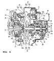
- FIG. 6 is a right side view of the power unit incorporating the V-belt CVT according to the second embodiment.
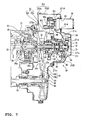
- FIG. 7 is a sectional view taken along the line C-C of FIG. 6 .
- FIG. 8 is a right side view of the V-belt CVT shown in FIG. 6 with its cover attached.
- Constituent parts of a power unit 204 according to the second embodiment which are similar or identical to those of the power unit 4 according to the above-described first embodiment are given the same reference numerals to save detailed description thereof.
- the power unit 204 of the second embodiment is an integral unit composed of an engine 20 and a V-belt CVT 130 for transmitting driving force of the engine 20 to driving wheels, attached to a side of a crankcase 21 of the engine 20.
- the power unit 204 of the second embodiment is similar to the power unit 4 of the first embodiment in that the sheave drive mechanism 39 is located around the primary sheave shaft 31 and that the electric motor 38 is located on the outer side of the sheave drive mechanism 39, but not in that the electric motor 38 for transmitting driving force to the sheave drive mechanism 39 is located above the primary sheave shaft 31, as viewed in the sheave shaft direction.
- a support member 271 in the power unit 204 of the second embodiment includes a bearing holding part 271 a for supporting the right end of the primary sheave shaft 31 via a roller bearing 72, four legs 271b extending in four directions from the bearing holding part 271 a, an annular coupling part 271 c for coupling the legs 271 b with a specific radius, a motor attachment part 271 d formed on the annular coupling part 271 c, and a sensor attachment part 271 e.
- the electric motor 38 is secured to the motor attachment part 271 d, which is formed on the upper side of the support member 271, from the outer side in the vehicle width direction.
- the constituent parts of the V-belt CVT 130 other than the electric motor 38 are accommodated in a transmission case 252 connected to a side of the crankcase 21.
- driving force of the electric motor 38 can be transmitted to the reciprocating gear 49 via a speed reduction gear mechanism 251 rotatably supported on a support shaft 253.
- the rotational speed sensor 74 is secured to the sensor attachment part 271 e of the support member 271, which has been moved to the secondary sheave 34 side above the horizontal plane including the primary sheave shaft 31.
- the power unit 204 of the second embodiment is additionally provided with a rotational speed sensor 84 for detecting the rotational speed of the secondary sheave shaft 33, and a measurement plate 83 as a part to be detected for the rotational speed sensor 84.
- the measurement plate 83 is located on a part of the secondary sheave shaft 33, from one side of which driving force for the driving wheels is output, on the other side with respect to the secondary sheave 34.
- the measurement plate 83 is composed of a disk 83a and projections for measurement 83b formed on the outer periphery of the disk 83a at regular intervals.
- the disk 83a is concentric with the secondary sheave shaft 33 and secured to an end of the secondary sheave shaft 33 on the other side with respect to the secondary sheave 34 (that is, the right end) by a bolt 85.
- the rotational speed sensor 84 is secured to an upper case 252b of the transmission case 252 so as to be located around the outer periphery of the measurement plate 83 and above a horizontal surface including the secondary sheave shaft 33.
- the rotational speed sensor 84 measures rotation of the secondary sheave shaft 33 based on the passing of the projections for measurement 83b of the measurement plate 83 to inform the control device for controlling the operation of the electric motor 38 of the measured rotational speed.
- the resin-made transmission case 252 is composed of a lower case 252a connected to a mating surface of the crankcase 21 on the right side in the crankshaft direction, and an upper case 252b removably attached to the lower case 252a.
- the upper case 252b as a cover of the V-belt CVT 130 is formed with a recess 252c for ensuring a space for the foot so that the projecting upper case 252b will not interfere with the foot.
- the upper case 252b is formed with a motor attachment hole 252d for allowing a housing of the electric motor 38 to pass therethrough as sealed by a seal member 60 (see FIG. 7 ).
- the upper case 252b is formed with a swelled portion 252e, in accordance with the above-described position of the rotational speed sensor 84, for covering the outside of the rotational speed sensor 84.
- the V-belt CVT 130 of the second embodiment is additionally provided with a rotational speed sensor 84 for detecting rotation of the secondary sheave shaft 33, it is possible to accurately grasp the actual speed change ratio of the V-belt CVT 130 based on information from the rotational speed sensor 84 and information from the rotational speed sensor 74 for detecting rotation of the primary sheave shaft 31, resulting in an optimum speed change ratio in accordance with the running condition such as running speed, accelerator opening, etc.
- the present teaching can be applied to straddie-type vehicles other than ATVs (all-terrain vehicles) such as disclosed in the above embodiments.
- the straddle-type vehicles according to the present teaching include motorcycles, motorbikes, scooters, buggies, golf carts, and other various vehicles having a seat where the rider straddles.
- a V-belt type CVT including: a primary sheave disposed on a primary sheave shaft, to one side of which driving force of an engine is input, and having a movable sheave half and a fixed sheave half to form a V-groove for receiving a belt; a secondary sheave disposed on a secondary sheave shaft, from which driving force for a driving wheel is output, and having a movable sheave half and a fixed sheave half to form a V-groove for receiving a belt; a V-belt received in the respective V-grooves of the primary sheave and the secondary sheave to transmit rotational driving force between both the sheaves; an electric motor; a control device for controlling the electric motor; and a sheave drive mechanism for transmitting driving force of the electric motor to the movable sheave half of the primary sheave to adjust respective groove widths of the
- the sheave drive mechanism for adjusting the respective groove widths of the primary sheave and the secondary sheave through the electric motor is located on an outer side of the movabie sheave half of the primary sheave, which is located on the other side of the primary sheave shaft with respect to the fixed sheave half of the primary sheave, and that the rotational speed sensor is located on the other side of the primary sheave shaft with respect to the sheave drive mechanism.
- the part to be detected has an outside diameter smaller than that of a reciprocating gear in the sheave drive mechanism.
- the rotational speed sensor is located around an outer periphery of the part to be detected.
- the part to be detected is located closer to the other end of the primary sheave shaft with respect to a roller bearing for supporting the other side of the primary sheave shaft, and has an outside diameter larger than that of the roller bearing.
- the rotational speed sensor is attached to a support member secured to a transmission case for supporting the other end side of the primary sheave shaft.
- At least one of a part of the sheave drive mechanism and the electric motor is attached to the support member.
- a V-belt type CVT including: a primary sheave disposed on a primary sheave shaft, to which driving force of an engine is input, and having a movable sheave half and a fixed sheave half to form a V-groove for receiving a belt; a secondary sheave disposed on a secondary sheave shaft, from one end of which driving force for a driving wheel is output, and having a movable sheave half and a fixed sheave half to form a V-groove for receiving a belt; a V-belt received in the respective V-grooves of the primary sheave and the secondary sheave to transmit rotational driving force between both the sheaves; an electric motor; a control device for controlling the electric motor; and a sheave drive mechanism for transmitting driving force of the electric motor to the movable sheave half of the primary sheave to adjust respective groove widths of the primary sheave
- the rotational speed sensor for detecting the rotational speed of the primary sheave shaft and the secondary sheave is disposed on a part of the primary sheave shaft, to one side of which driving force of the engine is input, on the other side with respect to the primary sheave. In this way, the rotational speed sensor can be located away from the cylinder block of the engine which can be hot, and also, it is not necessary to ensure an installation space for the rotational speed sensor around the outer periphery of the primary sheave.
- the V-belt CVT of the present invention is located below the seat with the rotational speed sensor located above a horizontal plane including the primary sheave shaft. In this way, a projection toward a lateral side of the vehicle body due to the installation of the rotational speed sensor comes above the toe placed on the footrest and thus does not prevent the rider from putting his/her foot in place.
- a V-belt continuously variable transmission comprising: a primary sheave disposed on a primary sheave shaft, to one side of which driving force of an engine is inpuA, and having a movable sheave half and a fixed sheave half to form a V-groove for receiving a belt; a secondary sheave disposed on a secondary sheave shaft, from which driving force for a driving wheel is output, and having a movable sheave half and a fixed sheave half to form a V-groove for receiving a belt; a V-belt received in the respective V-grooves of the primary sheave and the secondary sheave to transmit rotational driving force between both the sheaves; an electric motor; a control device for controlling the electric motor; and a sheave drive mechanism for transmitting driving force of the electric motor to the movable sheave half of the primary sheave to adjust respective groove widths of the primary sheave and
- the sheave drive mechanism for adjusting the respective groove widths of the primary sheave and the secondary sheave through the electric motor is located on an outer side of the movable sheave half of the primary sheave, which is located on the other side of the primary sheave shaft with respect to the fixed sheave half of the primary sheave, and wherein the rotational speed sensor is located on the other side of the primary sheave shaft with respect to the sheave drive mechanism.
- the part to be detected has an outside diameter smaller than that of a reciprocating gear in the sheave drive mechanism.
- the rotational speed sensor is located around an outer periphery of the part to be detected.
- the part to be detected is located closer to the other end of the primary sheave shaft with respect to a roller bearing for supporting the other side of the primary sheave shaft, and has an outside diameter larger than that of the roller bearing.
- the rotational speed sensor is attached to a support member secured to a transmission case for supporting the other end side of the primary sheave shaft.
- At least one of a part of the sheave drive mechanism and the electric motor is attached to the support member.
- a V-belt continuously variable transmission comprising: a primary sheave disposed on a primary sheave shaft, to which driving force of an engine is input, and having a movable sheave half and a fixed sheave half to form a V-groove for receiving a belt; a secondary sheave disposed on a secondary sheave shaft, from one end of which driving force for a driving wheel is output, and having a movable sheave half and a fixed sheave half to form a V-groove for receiving a belt; a V-belt received in the respective V-grooves of the primary sheave and the secondary sheave to transmit rotational driving force between both the sheaves; an electric motor; a control device for controlling the electric motor; and a sheave drive mechanism for transmitting driving force of the electric motor to the movable sheave half of the primary sheave to adjust respective groove widths of the primary sheave and the secondary
- a straddle-type vehicle having the V-belt continuously variable transmission according to any one of the first to eighth aspects disposed below a seat, and a footrest disposed on the other side of the primary sheave shaft of the V-belt continuously variable transmission, wherein the rotational speed sensor is located above a horizontal plane including the primary sheave shaft.
- the description still further discloses, in order to provide a compact yet durable V-belt continuously variable transmission (CVT) and straddle-type vehicle achieving speed change operation highly responsive to the vehicle running condition, an embodiment wherein in a V-belt CVT 30 of an ATV, a measurement plate 73 for a rotational speed sensor 74 for detecting the rotational speed of a primary sheave shaft 31 to control the speed change ratio is disposed on a part of the primary sheave shaft 31, to one side of which driving force of an engine 20 is input, on the other side with respect to a primary sheave 32.
- CVT continuously variable transmission
Landscapes
- Engineering & Computer Science (AREA)
- General Engineering & Computer Science (AREA)
- Mechanical Engineering (AREA)
- Transmissions By Endless Flexible Members (AREA)
- Devices For Conveying Motion By Means Of Endless Flexible Members (AREA)
- Control Of Transmission Device (AREA)
Abstract
Description
- The present invention relates to a V-belt continuously variable transmission (CVT) for transmitting driving force of an engine to a driving wheel, and a straddle-type vehicle having the V-belt CVT disposed below a seat, according to the preamble of
claims - Nowadays, there is an increasing demand for straddle-type vehicles called "ATV (all-terrain vehicle)."
- Also, there have been proposed various types of ATVs in which four wheels are provided, each wheel had a wide and low-pressure balloon tire or the like, on the left and right sides of the front and rear sides of a body frame, the upper part of the body frame is provided with steering handlebars, a fuel tank, and a straddle-type seat, sequentially from the front wheel side to the rear wheel side, and a V-belt CVT for transmitting driving force of an engine to driving wheels is disposed below the seat (see
Patent Document 1, for example). - The above V-belt CVT includes: a primary sheave disposed on a primary sheave shaft, to which driving force of the engine is input, and having a movable sheave half and a fixed sheave half to form a V-groove for receiving a belt; a secondary sheave disposed on a secondary sheave shaft, from which driving force for the driving wheels is output, and having a movable sheave half and a fixed sheave half to form a V-groove for receiving a belt; an endless V-belt received in the respective V-grooves of the primary sheave and the secondary sheave to transmit rotational driving force between both the sheaves; and a sheave drive mechanism for displacing the movable sheave half of the primary sheave in the axial direction to control the speed change ratio through resulting variations in respective groove widths of the primary sheave and the secondary sheave.
- A former type of sheave drive mechanism in general was the so-called centrifugal type which utilized centrifugal force produced according to the engine speed to displace a movable sheave half in the axial direction.
- However, when the road on which the vehicle is running turns from a flat road to a climbing road, for example, the sheave drive mechanism of the centrifugal type does not perform groove width control operation (namely, speed change operation) responsively according to changes in the road condition, irrespective of the intention of the rider, until the engine speed has actually fallen because of the increased load from the road. That is, the sheave drive mechanism has a problem of delayed response.
- In order to solve the problem of delayed response, another type of V-belt CVT for use in scooter-type motorcycles has been proposed, which includes: an electric motor; a control device for controlling the electric motor; a sheave drive mechanism for transmitting driving force of the electric motor to the movable sheave half of the primary sheave to adjust the respective groove widths of the primary sheave and the secondary sheave; and a rotational speed sensor for detecting rotation of the primary sheave or the secondary sheave to inform the control device of the detected rotation so that the control device can perform control according to the engine operating condition (see Patent Document 2, for example).
- In general, a scooter-type motorcycle is provided with an integral power unit composed of an engine and a V-belt CVT attached to a side of a crankcase of the engine. In such a scooter-type motorcycle, the power unit may be swingably suspended from a body frame to function as a swing arm for swingably supporting a rear wheel.
Patent Document 1:JP-A-2004-156657
Patent Document 2:JP-B-2852994 - For V-belt CVTs for use in ATVs, there is a need to electrically control the respective groove widths of the primary sheave and the secondary sheave in order to improve response in the speed change process.
- However, since ATVs are significanfly different in structure from scooter-type motorcycles, the installation method of electric motor and rotational speed sensor used in V-belt CVTs of scooter-type motorcycles cannot be used in ATVs as it is.
- That is, the engine and the V-belt CVT must be made compact In ATVs In which a footrest for the rider should be disposed on the outer side of the crankcase and the V-belt CVT. Thus, it is not easy to ensure an installation space for the electric motor and the rotational speed sensor, even on the outer side of the vehicle body. This is because the rotational speed sensor would project greatly to the outer side of the vehicle body and hence prevent the rider from putting his/her foot In place, thereby spoiling the usability.
- In the case where the rotational speed sensor is located around the outer periphery of the primary sheave or the secondary sheave, a transmission casing is upsized and hence the V-belt CVT cannot be made compact
- In addition, in the case where the rotational speed sensor is Installed near a heat producing part such as cylinder block of the engine, the service life of the rotational speed sensor and/or the measurement accuracy of the sensor may be reduced and therefore the original performance cannot be achieved.
- The document
DE 3829262 A1 discloses a V-belt continuously variable transmission comprising a primary sheave disposed on a prim ary sheave shaft to which driving force of an engine is input and a secondary sheave from which driving force for a driving wheel is output A V-belt is received in the respective V-grooves of the primary sheave and a secondary sheave to transmit rotational driving force between both the sheaves. A gear of a reduction gear unit disposed between the engine and the primary sheave shaft is used by a rotational speed sensor to detect a rotational speed of the gear. - The closest prior art document
US-A-4631043 discloses a V-belt continuously variable transmission comprising a primary sheave consisting of a fixed sheave and a movable sheave disposed on a primary sheave shaft having a first side and a second side arranged opposed to the first side. A driving force of an engine is input to the first side of the primary sheave shaft. A secondary sheave having movable and fixed sheave members is provided for driving a wheel of a vehicle. A V-belt is received In respective V-grooves of the primary and secondary sheaves to transmit rotational driving force between both the sheaves. The movable sheave of the primary sheave is disposed on the first side near the engine. A rotational speed sensor is provided for detecting a rotational speed of the fixed sheave. - The present invention is made in view of solving the foregoing problems, and therefore has an object to provide a compact yet durable V-belt CVT and straddle-type vehicle achieving speed change operation highly responsive to the vehicle running condition.
- This object is solved by the features of
claims - Further improvements are laid down in the subclaims.
- The V-belt continuously variable transmission preferably further comprises a sheave drive mechanism transmitting driving force of the electric motor to the movable sheave half of the primary sheave to adjust respective groove widths of the primary sheave and the secondary sheave through driving force of an electric motor.
- Further, preferably the sheave drive mechanism adjusting the respective groove widths of the primary sheave and the secondary sheave through the electric motor is located on an outer side of the movable sheave half of the primary sheave, which is located on the other side of the primary sheave shaft with respect to the fixed sheave half of the primary sheave, and the rotational speed sensor is located on the second side of the primary sheave shaft with respect to the sheave drive mechanism.
- Further, the part to be detected may have an outside diameter smaller than that of a reciprocating gear in the sheave drive mechanism.
- Further, the rotational speed sensor may be located around an outer periphery of the part to be detected.
- According to a further embodiment, the part to be detected is located closer to the second end of the primary sheave shaft with respect to a roller bearing for supporting the second side of the primary sheave shaft, and has an outside diameter larger than that of the roller bearing.
- Further, the rotational speed sensor may be attached to a support member secured to a transmission case for supporting the other end side of the primary sheave shaft.
- Further, at least one of a part of the sheave drive mechanism and the electric motor may be attached to the support member.
- The objective is further solved in an inventive manner by a V-belt continuously variable transmission, in particular for a straddle-type vehicle such as an all terrain vehicle, in particular according to one of the above embodiments, comprising: a primary sheave to which driving force of an engine is input; a secondary sheave disposed on a secondary sheave shaft, from a first side of which driving force for a driving wheel is output; and a V-belt received in the respective V-grooves of the primary sheave and the secondary sheave to transmit rotational driving force between both the sheaves, wherein a part to be detected for a rotational speed sensor for detecting a rotational speed of the secondary sheave shaft is located on a second side of the secondary sheave shaft with respect to the secondary sheave.
- Therein, the V-belt continuously variable transmission might further comprise a sheave drive mechanism for transmitting driving force of the electric motor to the movable sheave half of the primary sheave to adjust respective groove widths of the primary sheave and the second sheave.
- The above objective is further solved by a straddle-type vehicle having the V-belt continuously variable transmission according to one of the above embodiments disposed below a seat, and a footrest disposed on the second side of the primary sheave shaft of the V-belt continuously variable transmission, wherein the rotational speed sensor is located above a horizontal plane including the primary sheave shaft.
- In the following, the present invention is explained in greater detail with respect to several embodiments thereof in conjunction with the accompanying drawings, wherein:
- FIG. 1
- is a right side view of a straddle-type vehicle incorporating a power unit in which a V-belt CVT according to a first embodiment is assembled to an engine,
- FIG. 2
- is a plan view of the straddle-type vehicle shown in
FIG. 1 , - FIG. 3
- is a right side view of the power unit mounted in the straddle-type vehicle shown in
FIG. 1 with a cover of the V-belt CVT removed, - FIG. 4
- is a sectional view taken along the line A-A of
FIG. 3 , - FIG. 5
- is a right side view of the cover of the V-belt CVT shown in
FIG. 1 , - FIG. 6
- is a right side view of a power unit incorporating a V-belt CVT according to a second embodiment,
- FIG. 7
- is a sectional view taken along the line C-C of
FIG. 6 , and - FIG. 8
- is a right side view of the V-belt CVT shown in
FIG. 6 with its cover attached. -
- 1: ATV (straddle-type vehicle)
- 2: body frame
- 3: seat
- 4: power unit
- 11: front fender
- 15: footboard (footrest)
- 20: engine
- 22: crankshaft
- 25: centrifugal clutch mechanism
- 30: V-belt CVT
- 31: primary sheave shaft
- 32: primary sheave
- 32a: movable sheave half
- 32b: fixed sheave half
- 33: secondary sheave shaft
- 34: secondary sheave
- 34a: movable sheave half
- 34b: fixed sheave half
- 35: V-belt
- 38: electric motor
- 39: sheave drive mechanism
- 49: reciprocating gear
- 52: transmission case
- 52b: cover (upper case)
- 71: support member
- 72: bearing
- 73: measurement plate (part to be detected)
- 74: rotational speed sensor
- Preferred embodiments of a V-belt continuously variable transmission (CVT) and a straddle-type vehicle will hereinafter be described in detail with reference to the accompanying drawings.
-
FIGs. 1 through 5 illustrate a straddle-type vehicle incorporating a V-belt CVT according to a first embodiment.FIG. 1 is a right side view of the straddle-type vehicle incorporating a power unit in which the V-belt CVT according to the first embodiment is assembled to an engine.FIG. 2 is a plan view of the straddle-type vehicle shown inFIG. 1 .FIG. 3 is a right side view of the power unit mounted in the straddle-type vehicle shown inFIG. 1 with a cover of the V-belt CVT removed.FIG. 4 is a sectional view taken along the line A-A ofFIG. 3 .FIG. 5 is a right side view of the cover of the V-belt CVT shown inFIG. 1 . In this specification, "left" and "right" refer to the left and right from the rider's point of view. - An ATV (all-terrain vehicle) 1 shown in
FIGs. 1 and2 is a straddle-type vehicle having a seat 3, on which the operator (rider) straddles, located generally in the center of the upper part of a body frame 2, and apower unit 4 is located below the seat 3. Thepower unit 4 is an integral unit composed of anengine 20 and a V-belt CVT 30 for transmitting driving force of theengine 20 to driving wheels, attached to a side of acrankcase 21 of the engine 20 (seeFIGs. 3 and4 ). - The structure of the
ATV 1, and the structures of theengine 20 and the V-belt CVT 30 composing thepower unit 4 will be described sequentially below. - In the
ATV 1, the upper part of the body frame 2 in front of the seat 3 is provided with afuel tank 6 andsteering handlebars 5, sequentially from the seat 3 side. - Left and right
front wheels pressure balloon tire 8a, are disposed in the front part of the body frame 2 via a front wheel suspension device 7, and left and rightrear wheels pressure balloon tire 10a, are disposed in the rear part of the frame 2 via a rear wheel suspension device (not shown). - The body frame 2 is also provided with left and right
front fenders 11 for covering the upper side of the respectivefront wheels 8, left and rightrear fenders 12 for covering the upper side of the respectiverear wheels 10, andcarriers fenders footboard 15 as a footrest for supporting the foot of the rider on the lower left and right sides of the seat 3. Abumper 16 is provided at the front end of the frame 2. - As shown in
FIGs. 1 and3 , the body frame 2 is a double-cradle type in which a pair of left and right side frames 17, 17, made of steel tubing and formed generally in a rectangle which is longer sideways, are jointed by a number ofcross pipes 18 extending in the vehicle width direction. - As shown in
FIGs. 3 and4 , thepower unit 4 includes a water-cooled 4-cycle single-cylinder engine 20, and a V-belt CVT 30 bolted to the right side of theengine 20, with respect to the crankshaft direction. - As shown in
FIG. 3 , theengine 20 is mounted on the body frame 2 with an axis of its cylinder inclined upward and forward and a crankshaft 22 (seeFIG. 4 ) oriented horizontally in the vehicle width direction. The upper mating surface of acylinder block 23 is connected to acylinder head 24, and the lower mating surface of thecylinder block 23 is connected to acrankcase 21 accommodating thecrankshaft 22. - A generator (not shown) is mounted on the left end of the
crankshaft 22, and a centrifugalclutch mechanism 25 is mounted on the right end thereof, as shown inFIG. 4 . - The centrifugal
clutch mechanism 25 includes aninner drum 26 spline-coupled with thecrankshaft 22 to rotate together therewith, anouter drum 27 disposed to surround an outer periphery of theinner drum 26, and a one-way clutch 28 interposed between bosses of the pair ofdrums - As the rotational speed of the
crankshaft 22 increases, aweight 26a of theinner drum 26 is pressed against theouter drum 27 by centrifugal force so that theouter drum 27 rotates. - The one-way clutch 28 functions to transmit power from the rear wheels to the
crankshaft 22 in reverse in order to provide engine braking. - As shown in
FIG. 4 , the V-belt CVT 30 includes: a primary sheave 32 disposed on a primary sheave shaft 31, to one side of which driving force of the engine 20 is input from the crankshaft 22 via the centrifugal clutch mechanism 25, and having a movable sheave half 32a and a fixed sheave half 32b to form a V-groove 32c for receiving a belt; a secondary sheave 34 disposed on a secondary sheave shaft 33 (seeFIG. 2 ), from one side of which driving force for the driving wheels is output, and having a movable sheave half 34a and a fixed sheave half 34b to form a V-groove 34c for receiving a belt; a V-belt 35 received in the respective V-grooves 32c, 34c of the primary sheave 32 and the secondary sheave 34 to transmit rotational driving force between both the sheaves; an electric motor 38; a control device (not shown) for controlling the electric motor 38 according to the vehicle running condition (operating condition); a sheave drive mechanism 39 for transmitting driving force of the electric motor 38 to the movable sheave half 32a of the primary sheave 32 via a speed reduction mechanism 51 to control the respective groove widths of the primary sheave 32 and the secondary sheave 34; and a rotational speed sensor 74 for detecting rotation of the primary sheave shaft 31 to inform the control device of the detected rotation. - The
primary sheave shaft 31 is coaxial with thecrankshaft 22, and rotatably supported by the centrifugalclutch mechanism 25 and asupport member 71 such that the one side of theprimary sheave shaft 31 is on the right end of thecrankshaft 22. The one end of theprimary sheave shaft 31 facing the crankshaft 22 (left end) is formed integrally with askirt 31 a passing through an opening in the center of an end of aclutch cover 29 and surrounding the right end of thecrankshaft 22. Theskirt 31a is riveted or otherwise secured to theouter drum 27 of the centrifugalclutch mechanism 25. - The other end (right end) of the
primary sheave shaft 31 is rotatably supported, via aroller bearing 72, on the center of thesupport member 71 secured to thecrankcase 21. - As shown in
FIG. 3 , the die-castaluminum support member 71 includes abearing holding part 71a for supporting the right end of theprimary sheave shaft 31 via theroller bearing 72, fourlegs 71b extending in four directions from thebearing holding part 71a, anannular coupling part 71 c for coupling thelegs 71 b with a specific radius, amotor attachment part 71 d formed on theannular coupling part 71 c, and asensor attachment part 71 e. Ends of thelegs 71 b are bolted to thecrankcase 21. - The
primary sheave shaft 31 supported as described above becomes connected through the centrifugalclutch mechanism 25 to thecrankshaft 22 in order to rotate together therewith, when the rotational speed of thecrankshaft 22 reaches a specific speed or higher. - The base end of the
clutch cover 29 is secured to thecrankcase 21. A part of theclutch cover 29 around the opening at the center of its end is provided with abearing 41 for rotatably supporting theprimary sheave shaft 31, and aseal member 42 for sealing between the opening and the outer periphery of theskirt 31a. Theclutch cover 29 surrounds aspace 43 accommodating the centrifugalclutch mechanism 25 in a liquid-tight manner to prevent oil used for the centrifugalclutch mechanism 25 from leaking into abelt chamber 44 of the V-belt CVT 30. - In this embodiment, as shown in
FIG. 4 , themovable sheave half 32a of theprimary sheave 32 is located on the other side of the primary sheave shaft with respect to the fixedsheave half 32b of theprimary sheave 32. - Also, as shown in
FIG. 4 , the outer periphery of thesecondary sheave 34 is located adjacent to the outer periphery of theprimary sheave 32. This can effectively downsize the V-belt CVT 30 in the longitudinal direction of the vehicle for compactness. - In this embodiment, as shown in
FIG. 4 , thesheave drive mechanism 39 is located on the other side of theprimary sheave shaft 31 with respect to themovable sheave half 32a of theprimary sheave 32. - As shown in
FIG. 4 , thesheave drive mechanism 39 includes: aguide tube 46 spline-fitted or otherwise mounted on the outer periphery of theprimary sheave shaft 31 so as not to rotate relative thereto; aslider 48 mounted on the outer periphery of theguide tube 46 so as to be movable only axially and to which themovable sheave half 32a is secured; arotary slide member 47 rotationally coupled with the outer periphery of theslider 48 via a bearing so as not to move axially relative thereto and to which areciprocating gear 49 is secured; afeed guide tube 50 having a ball screw part screwed on therotary slide member 47 to move therotary slide member 47 in the axial direction of theprimary sheave shaft 31 according to the rotation direction and amount of thereciprocating gear 49; and aspeed reduction mechanism 51 for reducing the rotational speed of theelectric motor 38 and inputting the reduced rotation to thereciprocating gear 49. Thefeed guide part 50 is bolted to anouter member 54 for covering an end of therotary slide member 47, and theouter member 54 is bolted to thesupport member 71. - The
sheave drive mechanism 39 controls axial movement of themovable sheave half 32a according to the rotation input from theelectric motor 38 to thereciprocating gear 49 via thespeed reduction mechanism 51. - In the
power unit 4 of this embodiment, theelectric motor 38 is located closer to theprimary sheave shaft 31 than the speedreduction gear mechanism 51 of thesheave drive mechanism 39 is, as viewed in the sheave shaft direction, and secured to themotor attachment part 71 d of thesupport member 71 from the outer side in the vehicle width direction. That is, driving force of theelectric motor 38 can be transmitted to thereciprocating gear 49 via the speedreduction gear mechanism 51 rotatably supported on asupport shaft 53 which is located farther than amotor shaft 38a of theelectric motor 38 is. - In this way, the power transmission path from the
electric motor 38 to thereciprocating gear 49 via thesupport shaft 53 of the speedreduction gear mechanism 51 can be inverted to theprimary sheave shaft 31 side, thereby placing theelectric motor 38 closer to theprimary sheave shaft 31. - Thus, the imbalanced weight of the
power unit 4 due to the heavyelectric motor 38 can be improved. - The
movable sheave half 34a of thesecondary sheave 34 is normally urged by a spring member in the direction of reducing the groove width, so that the groove width is controlled based on the balance between the urging force and the tension of the wrapped V-belt 35. - Thus, when the groove width of the
primary sheave 32 is controlled by operation of thesheave drive mechanism 39 and hence the wrapping diameter of the V-belt 35 around theprimary sheave 32 is changed, the tension of the V-belt 35 and hence the groove width of thesecondary sheave 34 are changed accordingly for a specific speed change ratio. - As shown in
FIGs. 3 and4 , a part of theprimary sheave shaft 31 on the other side with respect to theprimary sheave 32 is provided with ameasurement plate 73 as a part to be detected for therotational speed sensor 74 in order to detect the rotational speed of theprimary sheave shaft 31. - As shown in
FIG. 3 , themeasurement plate 73 is composed of adisk 73a and projections formeasurement 73b formed on the outer periphery of thedisk 73a at regular intervals, and is smaller in outside diameter than thereciprocating gear 49 of thedrive mechanism 39. - In this embodiment, the
measurement plate 73 is located on the other side of theprimary sheave shaft 31 with respect to theroller bearing 72 for rotatably supporting the other side of theprimary sheave shaft 31, or located at the axial end of theprimary sheave shaft 31. Themeasurement plate 73 is made larger in outside diameter than theroller bearing 72. That is, themeasurement plate 73 is larger than theroller bearing 72 and smaller than thereciprocating gear 49 in outside diameter. - The
measurement plate 73 is concentric with theprimary sheave shaft 31 and secured to the axial end of theprimary sheave shaft 31 by a nut. - In this embodiment, the
rotational speed sensor 74 for detecting rotation of theprimary sheave shaft 31 based on rotation of themeasurement plate 73 is located on the other side of theprimary sheave shaft 31 with respect to thesheave drive mechanism 39 and around the outer periphery of themeasurement plate 73. - The
rotational speed sensor 74 is attached to thesupport member 71 via theattachment part 71 e located a suitable distance away from themeasurement plate 73 in a radially outward direction, and measures rotation of theprimary sheave shaft 31 based on the passing of the projections formeasurement 73b to inform the control device for controlling the operation of theelectric motor 38 of the measured rotational speed. - As shown in
FIG. 3 , therotational speed sensor 74 is attached to thesupport member 71 above a horizontal plane including theprimary sheave shaft 31. - Out of the constituent parts of the V-
belt CVT 30, those other than theelectric motor 38 are accommodated in atransmission case 52 connected to a side of thecrankcase 21. The resin-madetransmission case 52 is composed of alower case 52a connected to a mating surface of thecrankcase 21 on the right side in the crankshaft direction, and anupper case 52b removably attached to thelower case 52a, and defines thebelt chamber 44 beside thecrankcase 21. - As shown in
FIG. 5 , theupper case 52b as a cover of the V-belt CVT 30 is formed with arecess 52c for ensuring a space for the foot so that the projectingupper case 52b will not interfere with the foot. In addition, theupper case 52b is formed with amotor attachment hole 52d for allowing a housing of theelectric motor 38 to pass therethrough as sealed by a seal member 60 (seeFIG. 4 ). Further, theupper case 52b is formed with a swelledportion 52e, in accordance with the above-described position of therotational speed sensor 74, for covering the outside of therotational speed sensor 74. - The
footboard 15 is located on the outer side of the V-belt CVT 30 in the vehicle width direction, as shown inFIG. 2 , and below theprimary sheave shaft 31 and thesecondary sheave shaft 33. - In the
ATV 1 of this embodiment, as shown inFIG. 2 , the output of thesecondary sheave shaft 33 of thepower unit 4 is transmitted to anintermediate shaft 76 and anoutput shaft 77 via a suitable gear train, and then from theoutput shaft 77 to apower transmission shaft 79 disposed in the longitudinal direction of the vehicle via abevel gear mechanism 78. - The power is then transmitted from the
power transmission shaft 79 via a front/rear universal joint 62 to a front wheel drive shaft 63 and a rear wheel drive shaft 64, via which to the left and rightfront wheels 8 and the left and rightrear wheels 10, respectively. - In this embodiment, as shown in
FIG. 1 , anexhaust pipe 80 of theengine 20 is disposed above the V-belt CVT 30, and theelectric motor 38 is disposed in front of the V-belt CVT 30. - This arrangement can prevent the
electric motor 38 from interfering with the foot of the rider and theexhaust pipe 80. - As described above, in the V-
belt CVT 30 of theATV 1, theelectric motor 38 for controlling the respective groove widths of theprimary sheave 32 and thesecondary sheave 34 is located above the vicinity of the front end of thefootrest 15, providing a gap through which the toe can get in and out easily between the footrest and theelectric motor 38. - Thus, the
electric motor 38 does not prevent the rider from putting his/her foot in place. In addition, theelectric motor 38 is located away from thecylinder block 23 of theengine 20 which produces much heat and on the outer side of the vehicle body where the influence of heat from theengine 20 is less likely, and thus does not deteriorate because of heat from theengine 20. - In the V-
belt CVT 30 of the above embodiment, themeasurement plate 73, as a part to be detected for detecting rotational speed necessary to electrically control the respective groove widths of theprimary sheave 32 and thesecondary sheave 34, is located on a part of theprimary sheave shaft 31, to one side of which driving force of theengine 20 is input, on the other side with respect to theprimary sheave 32. In addition, therotational speed sensor 74 for detecting rotation of theprimary sheave shaft 31 based on rotation of themeasurement plate 73 is located around the outer periphery of themeasurement plate 73. - In this way, the
rotational speed sensor 74 can be located away from thecylinder block 23 of theengine 20 which can be hot. Also, it is not necessary to ensure an installation space for therotational speed sensor 74 around the outer periphery of theprimary sheave 32. - Thus, it is possible to obtain a compact yet durable V-
belt CVT 30 achieving speed change operation highly responsive to the vehicle running condition (engine operating condition). - In the
ATV 1 disclosed in the above embodiment, the V-belt CVT 30 suitable to achieve compactness is located below the seat 3 with therotational speed sensor 74 located above a horizontal plane including theprimary sheave shaft 31. In this way, a projection toward a lateral side of the vehicle body due to the installation of therotational speed sensor 74 comes above the toe placed on thefootboard 15 and thus does not prevent the rider from putting his/her foot in place. - Thus, it is possible to provide a
rotational speed sensor 74, which is necessary to electrically control the respective groove widths of thesheaves belt CVT 30, without sacrificing the possibility of compacting the V-belt CVT 30 located below the seat 3 and hindering the rider from putting his/her feet in place on both sides of the vehicle body, thereby achieving anATV 1 with speed change operation highly responsive to the vehicle running condition. - In the V-
belt CVT 30 of the above embodiment, thesheave drive mechanism 39 for controlling the respective groove widths of theprimary sheave 32 and thesecondary sheave 34 through theelectric motor 38 is located on the outer side (other side) of themovable sheave half 32a of theprimary sheave 32, which is located on the other side of theprimary sheave shaft 31 with respect to the fixedsheave half 32b of theprimary sheave 32, and therotational speed sensor 74 is located on the other side of theprimary sheave shaft 31 with respect to thesheave drive mechanism 39. - In this way, installing the
rotational speed sensor 74 at the other end of theprimary sheave shaft 31, where there are no parts with large outside diameter, can facilitate ensuring an installation space for therotational speed sensor 74 and prevent upsizing of the device due to the installation of therotational speed sensor 74. - In the V-
belt CVT 30 of the above embodiment, themeasurement plate 73 as a part to be detected for therotational speed sensor 74 is smaller in outside diameter than thereciprocating gear 49 in thesheave drive mechanism 39. In addition, therotational speed sensor 74 is located around the outer periphery of themeasurement plate 73. - With this structure, as shown in
FIG. 4 , an installation space for therotational speed sensor 74 can be ensured between themeasurement plate 73 at the axial end of theprimary sheave shaft 31 and theelectric motor 38, thereby achieving a compact V-belt CVT 30. - In the V-
belt CVT 30 of the above embodiment, themeasurement plate 73 is located closer to the other end of theprimary sheave shaft 31 than theroller bearing 72 for supporting the other side of theprimary sheave shaft 31 is, and larger in outside diameter than theroller bearing 72. - In this way, the
measurement plate 73 covers the axial end of theroller bearing 72, and thus can prevent foreign matter from entering theroller bearing 72 to maintain the performance of theroller bearing 72 for an extended period. - In the V-
belt CVT 30 of the above embodiment, therotational speed sensor 74 is attached to thesensor attachment part 71 e of thesupport member 71 secured to thecrankcase 21. Since thesupport member 71 is sturdily made to support theprimary sheave shaft 31, the use of thesupport member 71 allows secure attachment of therotational speed sensor 74. - In the V-
belt CVT 30 of the above embodiment, a part of thesheave drive mechanism 39 and theelectric motor 38 are also attached to thesupport member 71. In this way, the use of thesturdy support member 71 as an attachment bracket can achieve secure attachment of the respective parts without using an additional dedicated attachment bracket. - In the case where the
crankshaft 22 and theprimary sheave shaft 31 are connected via the clutch mechanism as in this embodiment, attaching therotational speed sensor 74 to the other side of theprimary sheave shaft 31 allows accurate detection of the rotational speed of theprimary sheave shaft 31. Thus, in addition to the above effects, the accurate detection of the rotational speed of theprimary sheave shaft 31 allows accurate grasping of the actual speed change ratio of the V-belt CVT 30, resulting in an optimum suitable speed change ratio in accordance with the running condition such as running speed, accelerator opening, etc. -
FIGs. 6 through 9 illustrate a power unit in which a V-belt CVT according to a second embodiment is assembled to an engine.FIG. 6 is a right side view of the power unit incorporating the V-belt CVT according to the second embodiment.FIG. 7 is a sectional view taken along the line C-C ofFIG. 6 .FIG. 8 is a right side view of the V-belt CVT shown inFIG. 6 with its cover attached. Constituent parts of apower unit 204 according to the second embodiment which are similar or identical to those of thepower unit 4 according to the above-described first embodiment are given the same reference numerals to save detailed description thereof. - As shown in
FIGs. 6 and7 , thepower unit 204 of the second embodiment is an integral unit composed of anengine 20 and a V-belt CVT 130 for transmitting driving force of theengine 20 to driving wheels, attached to a side of acrankcase 21 of theengine 20. - The
power unit 204 of the second embodiment is similar to thepower unit 4 of the first embodiment in that thesheave drive mechanism 39 is located around theprimary sheave shaft 31 and that theelectric motor 38 is located on the outer side of thesheave drive mechanism 39, but not in that theelectric motor 38 for transmitting driving force to thesheave drive mechanism 39 is located above theprimary sheave shaft 31, as viewed in the sheave shaft direction. - As shown in
FIG. 6 , asupport member 271 in thepower unit 204 of the second embodiment includes abearing holding part 271 a for supporting the right end of theprimary sheave shaft 31 via aroller bearing 72, fourlegs 271b extending in four directions from thebearing holding part 271 a, anannular coupling part 271 c for coupling thelegs 271 b with a specific radius, amotor attachment part 271 d formed on theannular coupling part 271 c, and asensor attachment part 271 e. - The
electric motor 38 is secured to themotor attachment part 271 d, which is formed on the upper side of thesupport member 271, from the outer side in the vehicle width direction. The constituent parts of the V-belt CVT 130 other than theelectric motor 38 are accommodated in atransmission case 252 connected to a side of thecrankcase 21. Thus, driving force of theelectric motor 38 can be transmitted to thereciprocating gear 49 via a speedreduction gear mechanism 251 rotatably supported on asupport shaft 253. - The
rotational speed sensor 74 is secured to thesensor attachment part 271 e of thesupport member 271, which has been moved to thesecondary sheave 34 side above the horizontal plane including theprimary sheave shaft 31. - In addition, as shown in
FIG. 7 , thepower unit 204 of the second embodiment is additionally provided with arotational speed sensor 84 for detecting the rotational speed of thesecondary sheave shaft 33, and ameasurement plate 83 as a part to be detected for therotational speed sensor 84. - The
measurement plate 83 is located on a part of thesecondary sheave shaft 33, from one side of which driving force for the driving wheels is output, on the other side with respect to thesecondary sheave 34. - As shown in
FIG. 6 , themeasurement plate 83 is composed of adisk 83a and projections formeasurement 83b formed on the outer periphery of thedisk 83a at regular intervals. Thedisk 83a is concentric with thesecondary sheave shaft 33 and secured to an end of thesecondary sheave shaft 33 on the other side with respect to the secondary sheave 34 (that is, the right end) by abolt 85. - The
rotational speed sensor 84 is secured to anupper case 252b of thetransmission case 252 so as to be located around the outer periphery of themeasurement plate 83 and above a horizontal surface including thesecondary sheave shaft 33. Therotational speed sensor 84 measures rotation of thesecondary sheave shaft 33 based on the passing of the projections formeasurement 83b of themeasurement plate 83 to inform the control device for controlling the operation of theelectric motor 38 of the measured rotational speed. - The resin-made
transmission case 252 is composed of alower case 252a connected to a mating surface of thecrankcase 21 on the right side in the crankshaft direction, and anupper case 252b removably attached to thelower case 252a. - As shown in
FIG. 8 , theupper case 252b as a cover of the V-belt CVT 130 is formed with arecess 252c for ensuring a space for the foot so that the projectingupper case 252b will not interfere with the foot. In addition, theupper case 252b is formed with amotor attachment hole 252d for allowing a housing of theelectric motor 38 to pass therethrough as sealed by a seal member 60 (seeFIG. 7 ). Further, theupper case 252b is formed with a swelledportion 252e, in accordance with the above-described position of therotational speed sensor 84, for covering the outside of therotational speed sensor 84. - Since the V-belt CVT 130 of the second embodiment is additionally provided with a
rotational speed sensor 84 for detecting rotation of thesecondary sheave shaft 33, it is possible to accurately grasp the actual speed change ratio of the V-belt CVT 130 based on information from therotational speed sensor 84 and information from therotational speed sensor 74 for detecting rotation of theprimary sheave shaft 31, resulting in an optimum speed change ratio in accordance with the running condition such as running speed, accelerator opening, etc. - The present teaching can be applied to straddie-type vehicles other than ATVs (all-terrain vehicles) such as disclosed in the above embodiments. For example, the straddle-type vehicles according to the present teaching include motorcycles, motorbikes, scooters, buggies, golf carts, and other various vehicles having a seat where the rider straddles.
- The structures of the rotational speed sensor and the part to be detected for the rotational speed sensor according to the present teaching are not limited to those disclosed in the above embodiments, but various modifications may be made thereto.
- The description above discloses (amongst others), in order to solve the above object, an embodiment of a V-belt type CVT including: a primary sheave disposed on a primary sheave shaft, to one side of which driving force of an engine is input, and having a movable sheave half and a fixed sheave half to form a V-groove for receiving a belt; a secondary sheave disposed on a secondary sheave shaft, from which driving force for a driving wheel is output, and having a movable sheave half and a fixed sheave half to form a V-groove for receiving a belt; a V-belt received in the respective V-grooves of the primary sheave and the secondary sheave to transmit rotational driving force between both the sheaves; an electric motor; a control device for controlling the electric motor; and a sheave drive mechanism for transmitting driving force of the electric motor to the movable sheave half of the primary sheave to adjust respective groove widths of the primary sheave and the secondary sheave, wherein a part to be detected for a rotational speed sensor for detecting a rotational speed of the primary sheave shaft is disposed on the other side of the primary sheave shaft with respect to the primary sheave.
- In the embodiment of the V-belt CVT with the above structure, it is preferred that the sheave drive mechanism for adjusting the respective groove widths of the primary sheave and the secondary sheave through the electric motor is located on an outer side of the movabie sheave half of the primary sheave, which is located on the other side of the primary sheave shaft with respect to the fixed sheave half of the primary sheave, and that the rotational speed sensor is located on the other side of the primary sheave shaft with respect to the sheave drive mechanism.
- In addition, in the embodiment of the V-belt CVT with the above structure, it is preferred that the part to be detected has an outside diameter smaller than that of a reciprocating gear in the sheave drive mechanism.
- In addition, in the embodiment of the V-belt CVT with the above structure, it is preferred that the rotational speed sensor is located around an outer periphery of the part to be detected.
- In addition, in the embodiment of the V-belt CVT with the above structure, it is preferred that the part to be detected is located closer to the other end of the primary sheave shaft with respect to a roller bearing for supporting the other side of the primary sheave shaft, and has an outside diameter larger than that of the roller bearing.
- In addition, in the embodiment of the V-belt CVT with the above structure, it is preferred that the rotational speed sensor is attached to a support member secured to a transmission case for supporting the other end side of the primary sheave shaft.
- In addition, in the embodiment of the V-belt CVT with the above structure, it is preferred that at least one of a part of the sheave drive mechanism and the electric motor is attached to the support member.
- Also, the description above discloses, in order to solve the above object, an embodiment of a V-belt type CVT including: a primary sheave disposed on a primary sheave shaft, to which driving force of an engine is input, and having a movable sheave half and a fixed sheave half to form a V-groove for receiving a belt; a secondary sheave disposed on a secondary sheave shaft, from one end of which driving force for a driving wheel is output, and having a movable sheave half and a fixed sheave half to form a V-groove for receiving a belt; a V-belt received in the respective V-grooves of the primary sheave and the secondary sheave to transmit rotational driving force between both the sheaves; an electric motor; a control device for controlling the electric motor; and a sheave drive mechanism for transmitting driving force of the electric motor to the movable sheave half of the primary sheave to adjust respective groove widths of the primary sheave and the secondary sheave, wherein a part to be detected for a rotational speed sensor for detecting a rotational speed of the secondary sheave shaft is located on the other side of the secondary sheave shaft with respect to the secondary sheave.
- The description above still further discloses, in order to solve the above object, an embodiment of a straddle-type vehicle having the V-belt CVT with the above structure disposed below a seat, and a footrest disposed on the other side of the primary sheave shaft of the V-belt CVT, wherein the rotational speed sensor is located above a horizontal plane including the primary sheave shaft.
- In the V-belt CVT constructed as described above, the rotational speed sensor for detecting the rotational speed of the primary sheave shaft and the secondary sheave is disposed on a part of the primary sheave shaft, to one side of which driving force of the engine is input, on the other side with respect to the primary sheave. In this way, the rotational speed sensor can be located away from the cylinder block of the engine which can be hot, and also, it is not necessary to ensure an installation space for the rotational speed sensor around the outer periphery of the primary sheave.
- Thus, it is possible to obtain a compact yet durable V-belt CVT achieving speed change operation highly responsive to the engine operating condition.
- In the straddle-type vehicle constructed as described above, the V-belt CVT of the present invention is located below the seat with the rotational speed sensor located above a horizontal plane including the primary sheave shaft. In this way, a projection toward a lateral side of the vehicle body due to the installation of the rotational speed sensor comes above the toe placed on the footrest and thus does not prevent the rider from putting his/her foot in place.
- Thus, it is possible to provide a rotational speed sensor without sacrificing the possibility of compacting the V-belt CVT located below the seat and hindering the rider from putting his/her feet in place on both sides of the vehicle body, thereby achieving a straddle-type vehicle with speed change operation highly responsive to the vehicle running condition.
- The description above further discloses, according to a preferred first aspect, a V-belt continuously variable transmission comprising: a primary sheave disposed on a primary sheave shaft, to one side of which driving force of an engine is inpuA, and having a movable sheave half and a fixed sheave half to form a V-groove for receiving a belt; a secondary sheave disposed on a secondary sheave shaft, from which driving force for a driving wheel is output, and having a movable sheave half and a fixed sheave half to form a V-groove for receiving a belt; a V-belt received in the respective V-grooves of the primary sheave and the secondary sheave to transmit rotational driving force between both the sheaves; an electric motor; a control device for controlling the electric motor; and a sheave drive mechanism for transmitting driving force of the electric motor to the movable sheave half of the primary sheave to adjust respective groove widths of the primary sheave and the secondary sheave, wherein a part to be detected for a rotational speed sensor for detecting a rotational speed of the primary sheave shaft is disposed on the other side of the primary sheave shaft with respect to the primary sheave.
- According to a preferred second aspect, the sheave drive mechanism for adjusting the respective groove widths of the primary sheave and the secondary sheave through the electric motor is located on an outer side of the movable sheave half of the primary sheave, which is located on the other side of the primary sheave shaft with respect to the fixed sheave half of the primary sheave, and wherein the rotational speed sensor is located on the other side of the primary sheave shaft with respect to the sheave drive mechanism.
- According to a preferred third aspect, the part to be detected has an outside diameter smaller than that of a reciprocating gear in the sheave drive mechanism.
- According to a preferred fourth aspect, the rotational speed sensor is located around an outer periphery of the part to be detected.
- According to a preferred fifth aspect, the part to be detected is located closer to the other end of the primary sheave shaft with respect to a roller bearing for supporting the other side of the primary sheave shaft, and has an outside diameter larger than that of the roller bearing.
- According to a preferred sixth aspect, the rotational speed sensor is attached to a support member secured to a transmission case for supporting the other end side of the primary sheave shaft.
- According to a preferred seventh aspect, at least one of a part of the sheave drive mechanism and the electric motor is attached to the support member.
- The description still further discloses, according to a preferred eighth aspect, a V-belt continuously variable transmission comprising: a primary sheave disposed on a primary sheave shaft, to which driving force of an engine is input, and having a movable sheave half and a fixed sheave half to form a V-groove for receiving a belt; a secondary sheave disposed on a secondary sheave shaft, from one end of which driving force for a driving wheel is output, and having a movable sheave half and a fixed sheave half to form a V-groove for receiving a belt; a V-belt received in the respective V-grooves of the primary sheave and the secondary sheave to transmit rotational driving force between both the sheaves; an electric motor; a control device for controlling the electric motor; and a sheave drive mechanism for transmitting driving force of the electric motor to the movable sheave half of the primary sheave to adjust respective groove widths of the primary sheave and the secondary sheave, wherein a part to be detected for a rotational speed sensor for detecting a rotational speed of the secondary sheave shaft is located on the other side of the secondary sheave shaft with respect to the secondary sheave.
- According to a preferred ninth aspect, there is disclosed a straddle-type vehicle having the V-belt continuously variable transmission according to any one of the first to eighth aspects disposed below a seat, and a footrest disposed on the other side of the primary sheave shaft of the V-belt continuously variable transmission, wherein the rotational speed sensor is located above a horizontal plane including the primary sheave shaft.
- The description still further discloses, in order to provide a compact yet durable V-belt continuously variable transmission (CVT) and straddle-type vehicle achieving speed change operation highly responsive to the vehicle running condition, an embodiment wherein in a V-
belt CVT 30 of an ATV, ameasurement plate 73 for arotational speed sensor 74 for detecting the rotational speed of aprimary sheave shaft 31 to control the speed change ratio is disposed on a part of theprimary sheave shaft 31, to one side of which driving force of anengine 20 is input, on the other side with respect to aprimary sheave 32.
Claims (11)
- V-belt continuously variable transmission (30), in particular for a straddle-type vehicle such as an all terrain vehicle (1), comprising:a primary sheave (32) disposed on a primary sheave shaft (31), said primary sheave shaft (31) having a first side and a second side arranged opposed to the first side, wherein driving force of an engine (20) is input to the first side of said primary sheave shaft (31),a secondary sheave (34) from which driving force for a driving wheel is output, anda V-belt (35) received in the respective V-grooves (32c, 34c) of the primary sheave (32) and the secondary sheave (34) to transmit rotational driving force between both the sheaves (32, 34),wherein the primary sheave (32) has a movable sheave half (32a) and a fixed sheave half (32b), said fixed sheave half (32b) is disposed on the first side and said movable sheave half (32a) is disposed on the second side, andcharacterized in that a part (73) to be detected by a rotational speed sensor (74) detecting a rotational speed of the primary sheave shaft (31) is disposed on the second side of the primary sheave shaft (31) and outside of the movable sheave half (32a).
- V-belt continuously variable transmission according to claim 1, characterized in that a sheave drive mechanism (39) is provided which is disposed on the outside of the movable sheave half (32a) and the rotational speed sensor (74) is disposed on the outside of the sheave drive mechanism (39).
- V-belt continuously variable transmission according to claim 2, characterized in that the sheave drive mechanism (39) transmits driving force of an electric motor (38) to the movable sheave half (32a) of the primary sheave (32) to adjust respective groove widths of the primary sheave (32) and the secondary sheave (34) through driving force of the electric motor (38).
- V-belt continuously variable transmission according to claim 2 or 3, characterized in that the part (73) to be detected has an outside diameter smaller than that of a reciprocating gear (49) in the sheave drive mechanism (39).
- V-belt continuously variable transmission according to one of the claims 1 to 4, characterized in that the rotational speed sensor (74) is located around an outer periphery of the part (73) to be detected.
- V-belt continuously variable transmission according to one of the claims 1 to 5, characterized in that the part (73) to be detected is located closer to the second side of the primary sheave shaft (31) with respect to the roller bearing (72) supporting the second side of the primary sheave shaft (31), and has an outside diameter larger than that of the roller bearing (72).
- V-belt continuously variable transmission according to one of the claims 1 to 6, characterized in that the rotational speed sensor (74) is attached to a support member (71; 271) secured to a transmission case (52; 252) supporting the second side of the primary sheave shaft (31).
- V-belt continuously variable transmission according to claim 7, characterized in that at least one of a part of the sheave drive mechanism (39) and the electric motor (38) is attached to the support member (71).
- V-belt continuously variable transmission, in particular for a straddle-type vehicle such as an all terrain vehicle, in particular according to one of the claims 1 to 8,
characterized by
a primary sheave (32) to which driving force of an engine (20) is input;
a secondary sheave (34) disposed on a secondary sheave shaft (33), from a first side of which driving force for a driving wheel is output;
and a V-belt (35) received in the respective V-grooves (32c, 34c) of the primary sheave (32) and the secondary sheave (34) to transmit rotational driving force between both the sheaves (32, 34),
wherein a part (83) to be detected for a rotational speed sensor (84) detecting a rotational speed of the secondary sheave shaft (33) is located on a second side of the secondary sheave shaft (34) with respect to the secondary sheave (34). - V-belt continuously variable transmission according to claim 9, characterized by a sheave drive mechanism (39) transmitting driving force of the electric motor (38) to the movable sheave half (32a) of the primary sheave (32) to adjust respective groove widths of the primary sheave (32) and the secondary sheave (34).
- Straddle-type vehicle having the V-belt continuously variable transmission according to one of the claims 1 to 10 disposed below a seat (3), and a footrest (15) disposed on the second side of the primary sheave shaft (31) of the V-belt continuously variable transmission, characterized in that the rotational speed sensor (74) is located above a horizontal plane including the primary sheave shaft (32).
Applications Claiming Priority (1)
| Application Number | Priority Date | Filing Date | Title |
|---|---|---|---|
| JP2005256703A JP2007071254A (en) | 2005-09-05 | 2005-09-05 | V-belt type continuously variable transmission and riding type vehicle |
Publications (3)
| Publication Number | Publication Date |
|---|---|
| EP1760366A2 EP1760366A2 (en) | 2007-03-07 |
| EP1760366A3 EP1760366A3 (en) | 2007-04-04 |
| EP1760366B1 true EP1760366B1 (en) | 2009-11-11 |
Family
ID=37624342
Family Applications (1)
| Application Number | Title | Priority Date | Filing Date |
|---|---|---|---|
| EP06018581A Not-in-force EP1760366B1 (en) | 2005-09-05 | 2006-09-05 | V-Belt continuously variable transmission and straddle-type vehicle |
Country Status (6)
| Country | Link |
|---|---|
| US (1) | US7771299B2 (en) |
| EP (1) | EP1760366B1 (en) |
| JP (1) | JP2007071254A (en) |
| AT (1) | ATE448429T1 (en) |
| DE (1) | DE602006010285D1 (en) |
| TW (1) | TWI314198B (en) |
Families Citing this family (22)
| Publication number | Priority date | Publication date | Assignee | Title |
|---|---|---|---|---|
| US20090038875A1 (en) * | 2005-05-12 | 2009-02-12 | Arctic Cat, Inc. | Off-road engine configuration with noise reduction system |
| US7438153B2 (en) * | 2005-05-12 | 2008-10-21 | Artic Cat Inc. | All-terrain vehicle engine configuration |
| US8494728B2 (en) * | 2007-09-03 | 2013-07-23 | Yamaha Hatsudoki Kabushiki Kaisha | Continuously variable transmission control device, continuously variable transmission, and vehicle equipped with the same |
| JP2009068586A (en) * | 2007-09-12 | 2009-04-02 | Aisin Ai Co Ltd | Device for supplying lubricating oil into rotary shaft in transmission |
| JP5027038B2 (en) * | 2008-03-31 | 2012-09-19 | 本田技研工業株式会社 | Forward / reverse switching mechanism |
| JP2010151237A (en) * | 2008-12-25 | 2010-07-08 | Kawasaki Heavy Ind Ltd | V-belt type continuously variable transmission |
| US8256563B2 (en) * | 2009-10-23 | 2012-09-04 | Yamaha Hatsudoki Kabushiki Kaisha | All terrain vehicle |
| US20110152020A1 (en) * | 2009-12-23 | 2011-06-23 | Brind Amour Francois | Electronically controlled continuously variable transmission with axially movable torque transmitting mechanism |
| WO2011108107A1 (en) * | 2010-03-04 | 2011-09-09 | トヨタ自動車株式会社 | Belt type stepless transmission for vehicle |
| CA2833245A1 (en) * | 2011-04-15 | 2012-10-18 | Bando Chemical Industries, Ltd. | Tensioner |
| US8834307B2 (en) * | 2011-10-06 | 2014-09-16 | Kawasaki Jukogyo Kabushiki Kaisha | Belt type continuously variable transmission |
| US8911312B2 (en) | 2011-10-06 | 2014-12-16 | Kawasaki Jukogyo Kabushiki Kaisha | Belt type continuously variable transmission |
| US9103428B2 (en) * | 2013-03-15 | 2015-08-11 | Kawasaki Jukogyo Kabushiki Kaisha | Structure for coupling V-belt type continuously variable transmission with engine |
| EP2837850A1 (en) * | 2013-07-05 | 2015-02-18 | Kanzaki Kokyukoki Mfg. Co., Ltd. | Belt type continuously variable transmission device |
| US10648554B2 (en) | 2014-09-02 | 2020-05-12 | Polaris Industries Inc. | Continuously variable transmission |
| JP6401076B2 (en) * | 2015-02-23 | 2018-10-03 | 株式会社ショーワ | Housing structure and steering device |
| JP6512967B2 (en) * | 2015-07-02 | 2019-05-15 | 株式会社クボタ | Work vehicle |
| JP6384504B2 (en) * | 2016-03-10 | 2018-09-05 | トヨタ自動車株式会社 | Continuously variable transmission |
| US9863523B2 (en) * | 2016-03-21 | 2018-01-09 | Textron Innovations Inc. | Continuously variable transmission |
| US10697532B2 (en) * | 2016-12-22 | 2020-06-30 | Polaris Industries Inc. | Housing for a transmission |
| CA3094207C (en) | 2018-03-19 | 2023-03-07 | Ronald ZURBRUEGG | Electronic cvt with friction clutch |
| US11649889B2 (en) | 2018-03-19 | 2023-05-16 | Polaris Industries Inc. | Continuously variable transmission |
Family Cites Families (13)
| Publication number | Priority date | Publication date | Assignee | Title |
|---|---|---|---|---|
| US4631043A (en) | 1984-05-03 | 1986-12-23 | Toyota Jidosha Kabushiki Kaisha | Hydraulic control apparatus for a continuously variable transmission |
| JP2697828B2 (en) | 1987-08-28 | 1998-01-14 | 株式会社日立製作所 | Automatic transmission for vehicles |
| US5052980A (en) * | 1989-02-13 | 1991-10-01 | Toyota Jidosha Kabushiki Kaisha | Hydraulic control apparatus for vehicle power transmitting system having continuously variable transmission |
| JP2852994B2 (en) | 1993-02-24 | 1999-02-03 | 愛知機械工業株式会社 | Continuously variable transmission |
| US5514047A (en) | 1993-03-08 | 1996-05-07 | Ford Motor Company | Continuously variable transmission |
| JP3061180B2 (en) * | 1998-09-08 | 2000-07-10 | 本田技研工業株式会社 | Transmission for vehicles |
| JP3267596B2 (en) * | 2000-05-19 | 2002-03-18 | ダイハツ工業株式会社 | Continuously variable transmission |
| US6694836B2 (en) | 2001-01-24 | 2004-02-24 | Kawasaki Jukogyo Kabushiki Kaisha | All-terrain vehicle |
| JP2002227947A (en) | 2001-01-29 | 2002-08-14 | Nsk Ltd | Pulley width adjusting device for continuously variable transmission |
| CN100510348C (en) * | 2002-04-08 | 2009-07-08 | 雅马哈发动机株式会社 | Engine |
| KR100541912B1 (en) * | 2002-09-05 | 2006-01-10 | 쟈트코 가부시키가이샤 | V-Belt Type Continuously Variable Transmission |
| JP2004156657A (en) | 2002-11-05 | 2004-06-03 | Yamaha Motor Co Ltd | Driving belt cooling structure of engine |
| US7350439B2 (en) * | 2004-04-27 | 2008-04-01 | General Motors Corporation | Transmission case cover with radial inflow channel |
-
2005
- 2005-09-05 JP JP2005256703A patent/JP2007071254A/en active Pending
-
2006
- 2006-08-10 TW TW095129425A patent/TWI314198B/en active
- 2006-08-25 US US11/467,201 patent/US7771299B2/en active Active
- 2006-09-05 AT AT06018581T patent/ATE448429T1/en not_active IP Right Cessation
- 2006-09-05 DE DE602006010285T patent/DE602006010285D1/en active Active
- 2006-09-05 EP EP06018581A patent/EP1760366B1/en not_active Not-in-force
Also Published As
| Publication number | Publication date |
|---|---|
| EP1760366A3 (en) | 2007-04-04 |
| TWI314198B (en) | 2009-09-01 |
| TW200722661A (en) | 2007-06-16 |
| US7771299B2 (en) | 2010-08-10 |
| ATE448429T1 (en) | 2009-11-15 |
| JP2007071254A (en) | 2007-03-22 |
| DE602006010285D1 (en) | 2009-12-24 |
| EP1760366A2 (en) | 2007-03-07 |
| US20070054765A1 (en) | 2007-03-08 |
Similar Documents
| Publication | Publication Date | Title |
|---|---|---|
| EP1760366B1 (en) | V-Belt continuously variable transmission and straddle-type vehicle | |
| US7905803B2 (en) | Straddle-type vehicle and power unit | |
| US7556576B2 (en) | V-belt continuously variable transmission and straddle-type vehicle | |
| US7398753B2 (en) | Engine with built-in continuously variable transmission | |
| EP1741964B1 (en) | Vehicle power unit and vehicle comprising such a vehicle power unit | |
| US7575083B2 (en) | Automatic transmission for a motorcycle | |
| EP1770307B1 (en) | V-belt type continuously variable transmission for small-sized vehicle and saddle-riding type vehicle | |
| US8123658B2 (en) | Continuously variable transmission, vehicle having the continuously variable transmission, and control device and control method for the continuously variable transmission | |
| EP1880934A2 (en) | Motorcycle | |
| JPH0825498B2 (en) | Saddle-type four-wheeled vehicle for running on rough terrain | |
| EP1476679A1 (en) | Three-wheeled vehicle with a continuously variable transmission | |
| US7862459B2 (en) | Transmission, power unit having the same, vehicle, controller for transmission, and method of controlling transmission | |
| US20130055841A1 (en) | Gear shift control device of saddle ride type vehicle | |
| US7540348B2 (en) | Power unit for motorcycle and motorcycle | |
| US7434645B2 (en) | Swing arm structure in motorcycle | |
| EP1375860B1 (en) | Power unit for motorcycle | |
| JP5095359B2 (en) | VEHICLE, ITS CONTROL DEVICE, AND VEHICLE ABNORMALITY DETECTING METHOD | |
| JP4939459B2 (en) | V belt type continuously variable transmission | |
| US11624436B2 (en) | Vehicle having an air-cooled continuously variable transmission | |
| JP2005121168A (en) | Bearing structure of rotating shaft | |
| JP2009190486A (en) | Power unit for small vehicle | |
| JP2009190487A (en) | Power unit for small vehicle |
Legal Events
| Date | Code | Title | Description |
|---|---|---|---|
| PUAI | Public reference made under article 153(3) epc to a published international application that has entered the european phase |
Free format text: ORIGINAL CODE: 0009012 |
|
| PUAL | Search report despatched |
Free format text: ORIGINAL CODE: 0009013 |
|
| AK | Designated contracting states |
Kind code of ref document: A2 Designated state(s): AT BE BG CH CY CZ DE DK EE ES FI FR GB GR HU IE IS IT LI LT LU LV MC NL PL PT RO SE SI SK TR |
|
| AX | Request for extension of the european patent |
Extension state: AL BA HR MK YU |
|
| AK | Designated contracting states |
Kind code of ref document: A3 Designated state(s): AT BE BG CH CY CZ DE DK EE ES FI FR GB GR HU IE IS IT LI LT LU LV MC NL PL PT RO SE SI SK TR |
|
| AX | Request for extension of the european patent |
Extension state: AL BA HR MK YU |
|
| RIC1 | Information provided on ipc code assigned before grant |
Ipc: F16H 63/06 20060101ALI20070226BHEP Ipc: F16H 9/18 20060101AFI20070130BHEP Ipc: F16H 61/662 20060101ALI20070226BHEP |
|
| 17P | Request for examination filed |
Effective date: 20070411 |
|
| 17Q | First examination report despatched |
Effective date: 20070518 |
|
| AKX | Designation fees paid |
Designated state(s): AT BE BG CH CY CZ DE DK EE ES FI FR GB GR HU IE IS IT LI LT LU LV MC NL PL PT RO SE SI SK TR |
|
| GRAP | Despatch of communication of intention to grant a patent |
Free format text: ORIGINAL CODE: EPIDOSNIGR1 |
|
| GRAS | Grant fee paid |
Free format text: ORIGINAL CODE: EPIDOSNIGR3 |
|
| GRAA | (expected) grant |
Free format text: ORIGINAL CODE: 0009210 |
|
| AK | Designated contracting states |
Kind code of ref document: B1 Designated state(s): AT BE BG CH CY CZ DE DK EE ES FI FR GB GR HU IE IS IT LI LT LU LV MC NL PL PT RO SE SI SK TR |
|
| REG | Reference to a national code |
Ref country code: GB Ref legal event code: FG4D |
|
| REG | Reference to a national code |
Ref country code: CH Ref legal event code: EP |
|
| REG | Reference to a national code |
Ref country code: IE Ref legal event code: FG4D |
|
| REF | Corresponds to: |
Ref document number: 602006010285 Country of ref document: DE Date of ref document: 20091224 Kind code of ref document: P |
|
| NLV1 | Nl: lapsed or annulled due to failure to fulfill the requirements of art. 29p and 29m of the patents act | ||
| LTIE | Lt: invalidation of european patent or patent extension |
Effective date: 20091111 |
|
| PG25 | Lapsed in a contracting state [announced via postgrant information from national office to epo] |
Ref country code: FI Free format text: LAPSE BECAUSE OF FAILURE TO SUBMIT A TRANSLATION OF THE DESCRIPTION OR TO PAY THE FEE WITHIN THE PRESCRIBED TIME-LIMIT Effective date: 20091111 Ref country code: IS Free format text: LAPSE BECAUSE OF FAILURE TO SUBMIT A TRANSLATION OF THE DESCRIPTION OR TO PAY THE FEE WITHIN THE PRESCRIBED TIME-LIMIT Effective date: 20100311 Ref country code: ES Free format text: LAPSE BECAUSE OF FAILURE TO SUBMIT A TRANSLATION OF THE DESCRIPTION OR TO PAY THE FEE WITHIN THE PRESCRIBED TIME-LIMIT Effective date: 20100222 Ref country code: PT Free format text: LAPSE BECAUSE OF FAILURE TO SUBMIT A TRANSLATION OF THE DESCRIPTION OR TO PAY THE FEE WITHIN THE PRESCRIBED TIME-LIMIT Effective date: 20100311 Ref country code: SE Free format text: LAPSE BECAUSE OF FAILURE TO SUBMIT A TRANSLATION OF THE DESCRIPTION OR TO PAY THE FEE WITHIN THE PRESCRIBED TIME-LIMIT Effective date: 20091111 Ref country code: LT Free format text: LAPSE BECAUSE OF FAILURE TO SUBMIT A TRANSLATION OF THE DESCRIPTION OR TO PAY THE FEE WITHIN THE PRESCRIBED TIME-LIMIT Effective date: 20091111 |
|
| PG25 | Lapsed in a contracting state [announced via postgrant information from national office to epo] |
Ref country code: PL Free format text: LAPSE BECAUSE OF FAILURE TO SUBMIT A TRANSLATION OF THE DESCRIPTION OR TO PAY THE FEE WITHIN THE PRESCRIBED TIME-LIMIT Effective date: 20091111 Ref country code: SI Free format text: LAPSE BECAUSE OF FAILURE TO SUBMIT A TRANSLATION OF THE DESCRIPTION OR TO PAY THE FEE WITHIN THE PRESCRIBED TIME-LIMIT Effective date: 20091111 Ref country code: CY Free format text: LAPSE BECAUSE OF FAILURE TO SUBMIT A TRANSLATION OF THE DESCRIPTION OR TO PAY THE FEE WITHIN THE PRESCRIBED TIME-LIMIT Effective date: 20091111 Ref country code: LV Free format text: LAPSE BECAUSE OF FAILURE TO SUBMIT A TRANSLATION OF THE DESCRIPTION OR TO PAY THE FEE WITHIN THE PRESCRIBED TIME-LIMIT Effective date: 20091111 |
|
| PG25 | Lapsed in a contracting state [announced via postgrant information from national office to epo] |
Ref country code: BE Free format text: LAPSE BECAUSE OF FAILURE TO SUBMIT A TRANSLATION OF THE DESCRIPTION OR TO PAY THE FEE WITHIN THE PRESCRIBED TIME-LIMIT Effective date: 20091111 Ref country code: AT Free format text: LAPSE BECAUSE OF FAILURE TO SUBMIT A TRANSLATION OF THE DESCRIPTION OR TO PAY THE FEE WITHIN THE PRESCRIBED TIME-LIMIT Effective date: 20091111 |
|
| PG25 | Lapsed in a contracting state [announced via postgrant information from national office to epo] |
Ref country code: BG Free format text: LAPSE BECAUSE OF FAILURE TO SUBMIT A TRANSLATION OF THE DESCRIPTION OR TO PAY THE FEE WITHIN THE PRESCRIBED TIME-LIMIT Effective date: 20100211 Ref country code: RO Free format text: LAPSE BECAUSE OF FAILURE TO SUBMIT A TRANSLATION OF THE DESCRIPTION OR TO PAY THE FEE WITHIN THE PRESCRIBED TIME-LIMIT Effective date: 20091111 Ref country code: DK Free format text: LAPSE BECAUSE OF FAILURE TO SUBMIT A TRANSLATION OF THE DESCRIPTION OR TO PAY THE FEE WITHIN THE PRESCRIBED TIME-LIMIT Effective date: 20091111 Ref country code: EE Free format text: LAPSE BECAUSE OF FAILURE TO SUBMIT A TRANSLATION OF THE DESCRIPTION OR TO PAY THE FEE WITHIN THE PRESCRIBED TIME-LIMIT Effective date: 20091111 |
|
| PG25 | Lapsed in a contracting state [announced via postgrant information from national office to epo] |
Ref country code: CZ Free format text: LAPSE BECAUSE OF FAILURE TO SUBMIT A TRANSLATION OF THE DESCRIPTION OR TO PAY THE FEE WITHIN THE PRESCRIBED TIME-LIMIT Effective date: 20091111 Ref country code: SK Free format text: LAPSE BECAUSE OF FAILURE TO SUBMIT A TRANSLATION OF THE DESCRIPTION OR TO PAY THE FEE WITHIN THE PRESCRIBED TIME-LIMIT Effective date: 20091111 |
|
| PLBE | No opposition filed within time limit |
Free format text: ORIGINAL CODE: 0009261 |
|
| STAA | Information on the status of an ep patent application or granted ep patent |
Free format text: STATUS: NO OPPOSITION FILED WITHIN TIME LIMIT |
|
| 26N | No opposition filed |
Effective date: 20100812 |
|
| PG25 | Lapsed in a contracting state [announced via postgrant information from national office to epo] |
Ref country code: GR Free format text: LAPSE BECAUSE OF FAILURE TO SUBMIT A TRANSLATION OF THE DESCRIPTION OR TO PAY THE FEE WITHIN THE PRESCRIBED TIME-LIMIT Effective date: 20100212 |
|
| PGFP | Annual fee paid to national office [announced via postgrant information from national office to epo] |
Ref country code: FR Payment date: 20100921 Year of fee payment: 5 |
|
| PGFP | Annual fee paid to national office [announced via postgrant information from national office to epo] |
Ref country code: GB Payment date: 20100901 Year of fee payment: 5 |
|
| PGFP | Annual fee paid to national office [announced via postgrant information from national office to epo] |
Ref country code: DE Payment date: 20100901 Year of fee payment: 5 |
|
| PG25 | Lapsed in a contracting state [announced via postgrant information from national office to epo] |
Ref country code: IT Free format text: LAPSE BECAUSE OF FAILURE TO SUBMIT A TRANSLATION OF THE DESCRIPTION OR TO PAY THE FEE WITHIN THE PRESCRIBED TIME-LIMIT Effective date: 20091111 |
|
| PG25 | Lapsed in a contracting state [announced via postgrant information from national office to epo] |
Ref country code: MC Free format text: LAPSE BECAUSE OF NON-PAYMENT OF DUE FEES Effective date: 20100930 |
|
| REG | Reference to a national code |
Ref country code: CH Ref legal event code: PL |
|
| PG25 | Lapsed in a contracting state [announced via postgrant information from national office to epo] |
Ref country code: LI Free format text: LAPSE BECAUSE OF NON-PAYMENT OF DUE FEES Effective date: 20100930 Ref country code: CH Free format text: LAPSE BECAUSE OF NON-PAYMENT OF DUE FEES Effective date: 20100930 Ref country code: IE Free format text: LAPSE BECAUSE OF NON-PAYMENT OF DUE FEES Effective date: 20100905 |
|
| GBPC | Gb: european patent ceased through non-payment of renewal fee |
Effective date: 20110905 |
|
| REG | Reference to a national code |
Ref country code: FR Ref legal event code: ST Effective date: 20120531 |
|
| REG | Reference to a national code |
Ref country code: DE Ref legal event code: R119 Ref document number: 602006010285 Country of ref document: DE Effective date: 20120403 |
|
| PG25 | Lapsed in a contracting state [announced via postgrant information from national office to epo] |
Ref country code: DE Free format text: LAPSE BECAUSE OF NON-PAYMENT OF DUE FEES Effective date: 20120403 |
|
| PG25 | Lapsed in a contracting state [announced via postgrant information from national office to epo] |
Ref country code: GB Free format text: LAPSE BECAUSE OF NON-PAYMENT OF DUE FEES Effective date: 20110905 Ref country code: FR Free format text: LAPSE BECAUSE OF NON-PAYMENT OF DUE FEES Effective date: 20110930 |
|
| PG25 | Lapsed in a contracting state [announced via postgrant information from national office to epo] |
Ref country code: HU Free format text: LAPSE BECAUSE OF FAILURE TO SUBMIT A TRANSLATION OF THE DESCRIPTION OR TO PAY THE FEE WITHIN THE PRESCRIBED TIME-LIMIT Effective date: 20100512 Ref country code: LU Free format text: LAPSE BECAUSE OF NON-PAYMENT OF DUE FEES Effective date: 20100905 Ref country code: NL Free format text: LAPSE BECAUSE OF FAILURE TO SUBMIT A TRANSLATION OF THE DESCRIPTION OR TO PAY THE FEE WITHIN THE PRESCRIBED TIME-LIMIT Effective date: 20091111 |
|
| PG25 | Lapsed in a contracting state [announced via postgrant information from national office to epo] |
Ref country code: TR Free format text: LAPSE BECAUSE OF FAILURE TO SUBMIT A TRANSLATION OF THE DESCRIPTION OR TO PAY THE FEE WITHIN THE PRESCRIBED TIME-LIMIT Effective date: 20091111 |