WO2011108107A1 - Belt type stepless transmission for vehicle - Google Patents
Belt type stepless transmission for vehicle Download PDFInfo
- Publication number
- WO2011108107A1 WO2011108107A1 PCT/JP2010/053576 JP2010053576W WO2011108107A1 WO 2011108107 A1 WO2011108107 A1 WO 2011108107A1 JP 2010053576 W JP2010053576 W JP 2010053576W WO 2011108107 A1 WO2011108107 A1 WO 2011108107A1
- Authority
- WO
- WIPO (PCT)
- Prior art keywords
- fixed sheave
- sheave
- parking gear
- fixed
- continuously variable
- Prior art date
Links
Images


Classifications
-
- F—MECHANICAL ENGINEERING; LIGHTING; HEATING; WEAPONS; BLASTING
- F16—ENGINEERING ELEMENTS AND UNITS; GENERAL MEASURES FOR PRODUCING AND MAINTAINING EFFECTIVE FUNCTIONING OF MACHINES OR INSTALLATIONS; THERMAL INSULATION IN GENERAL
- F16H—GEARING
- F16H9/00—Gearings for conveying rotary motion with variable gear ratio, or for reversing rotary motion, by endless flexible members
- F16H9/02—Gearings for conveying rotary motion with variable gear ratio, or for reversing rotary motion, by endless flexible members without members having orbital motion
- F16H9/04—Gearings for conveying rotary motion with variable gear ratio, or for reversing rotary motion, by endless flexible members without members having orbital motion using belts, V-belts, or ropes
- F16H9/12—Gearings for conveying rotary motion with variable gear ratio, or for reversing rotary motion, by endless flexible members without members having orbital motion using belts, V-belts, or ropes engaging a pulley built-up out of relatively axially-adjustable parts in which the belt engages the opposite flanges of the pulley directly without interposed belt-supporting members
- F16H9/16—Gearings for conveying rotary motion with variable gear ratio, or for reversing rotary motion, by endless flexible members without members having orbital motion using belts, V-belts, or ropes engaging a pulley built-up out of relatively axially-adjustable parts in which the belt engages the opposite flanges of the pulley directly without interposed belt-supporting members using two pulleys, both built-up out of adjustable conical parts
- F16H9/18—Gearings for conveying rotary motion with variable gear ratio, or for reversing rotary motion, by endless flexible members without members having orbital motion using belts, V-belts, or ropes engaging a pulley built-up out of relatively axially-adjustable parts in which the belt engages the opposite flanges of the pulley directly without interposed belt-supporting members using two pulleys, both built-up out of adjustable conical parts only one flange of each pulley being adjustable
-
- F—MECHANICAL ENGINEERING; LIGHTING; HEATING; WEAPONS; BLASTING
- F16—ENGINEERING ELEMENTS AND UNITS; GENERAL MEASURES FOR PRODUCING AND MAINTAINING EFFECTIVE FUNCTIONING OF MACHINES OR INSTALLATIONS; THERMAL INSULATION IN GENERAL
- F16H—GEARING
- F16H63/00—Control outputs from the control unit to change-speed- or reversing-gearings for conveying rotary motion or to other devices than the final output mechanism
- F16H63/02—Final output mechanisms therefor; Actuating means for the final output mechanisms
- F16H63/30—Constructional features of the final output mechanisms
- F16H63/34—Locking or disabling mechanisms
- F16H63/3416—Parking lock mechanisms or brakes in the transmission
- F16H63/3425—Parking lock mechanisms or brakes in the transmission characterised by pawls or wheels
Definitions
- the present invention relates to a belt-type continuously variable transmission for a vehicle, and more particularly to a technique for suppressing the falling of a fixed sheave.
- variable groove width pulleys of Patent Documents 1 to 3 are movable in the axial direction on the rotary shaft so as to form a V-groove between the fixed sheave fixed to the rotary shaft and the fixed sheave. And a movable sheave provided around the shaft so as not to rotate relative to the shaft.
- the transmission belt is clamped between the fixed sheave and the movable sheave.
- the fixed sheave will be tilted to the opposite side of the transmission belt with the base portion of the fixed sheave, that is, the inner periphery as a fulcrum. The moment is applied.
- Patent Document 4 describes an elastic member such as a disc spring that urges the fixed sheave from the side opposite to the movable sheave to resist the reaction force.
- Patent Document 5 describes that in order to resist the reaction force, an oil chamber is formed adjacent to the surface of the fixed sheave opposite to the movable sheave and hydraulic pressure is supplied to the oil chamber. Yes.
- this complicates the configuration and requires significant changes in parts such as adding a member for forming the oil chamber and an oil passage for supplying hydraulic pressure to the oil chamber. There was a drawback.
- the present invention has been made against the background of the above circumstances, and an object of the present invention is to provide a belt type continuously variable transmission for a vehicle that can suppress the falling of a fixed sheave without adding parts. It is in.
- the gist of the invention according to claim 1 for achieving this object is that: (a) an input shaft and an output shaft provided in parallel with each other, and a pair provided on the outer peripheral side of the input shaft and the output shaft And a transmission belt wound around each of the V-grooves of the pair of variable-width pulleys, and changing the groove width of the V-groove to change the engagement diameter of the transmission belt.
- a belt-type continuously variable transmission for a vehicle that continuously changes a gear ratio wherein (b) the groove width variable pulley includes a fixed sheave fixed to one outer peripheral surface of the input shaft and the output shaft; A movable sheave provided so as to be relatively non-rotatable on the one shaft and relatively movable in the axial direction of the one shaft so as to form the V-groove between the fixed sheave, (c) ⁇
- the parking gear which has an annular protrusion which contact
- the gist of the invention according to claim 2 is that, in the invention according to claim 1, the annular protrusion of the parking gear is configured such that the transmission of the fixed sheave on the side opposite to the movable sheave is the transmission. It is in contact with the radial position corresponding to the maximum hook diameter of the belt.
- the gist of the invention according to claim 3 is that, in the invention according to claim 1 or 2, the annular protrusion of the parking gear is the fixed sheave of the variable groove width pulley provided on the output shaft. It is in contact with the surface opposite to the movable sheave.
- the annular protrusion of the parking gear is located on a side opposite to the movable sheave of the fixed sheave. That is, it is inserted into an annular fitting portion projecting from the outer peripheral portion of the surface to the parking gear side and engaged in the radial direction.
- the annular protrusion of the parking gear is located on a side opposite to the movable sheave of the fixed sheave. It exists in being engaged with the engaging tooth formed in the outer peripheral part of the surface in the circumferential direction.
- the parking gear is arranged on the fixed sheave from an inner peripheral side of the annular protrusion of the main body.
- a stopper portion projecting toward a surface opposite to the movable sheave of the movable sheave, and the pressing force to the fixed sheave from the annular projection previously applied to the fixed sheave reaches a predetermined value. Then, the stopper part comes into contact with the surface on the opposite side to limit the application of the pressing force from the annular protrusion to the fixed sheave.
- the gist of the invention according to claim 7 is that, in the invention according to any one of claims 1 to 6, the parking gear is a nut screwed to the shaft end portion of the one shaft. By being tightened by the screw, the pressure is clamped in the axial direction between the fixed sheave.
- the groove width variable pulley is formed between the fixed sheave fixed to one outer peripheral surface of the input shaft and the output shaft and the fixed sheave.
- a movable sheave provided so as to be relatively non-rotatable on the one shaft and relatively movable in the axial direction of the one shaft so as to form a V-groove for holding the transmission belt on the shaft.
- the disc-shaped main body fixed to the one shaft, and projecting from the main body toward the surface opposite to the movable sheave of the fixed sheave, Since the parking gear having an annular protrusion that contacts the outer peripheral side of the minimum engagement diameter of the transmission belt is provided on the opposite surface, the transmission belt is pinched between the fixed sheave and the movable sheave. Fixed sheave Even if it receives a reaction force in the axial direction from the belt, only a relatively simple change of forming the annular protrusion on the conventionally used parking gear has been made. Since the outer peripheral side of the opposite surface is supported with respect to the minimum engagement diameter of the transmission belt, it is possible to suppress the falling of the fixed sheave without adding any parts and with a relatively simple configuration.
- the annular protrusion of the parking gear corresponds to the maximum engagement diameter of the transmission belt on the surface of the fixed sheave opposite to the movable sheave. Because it contacts the radial position, even if the fixed sheave receives the maximum reaction force in the axial direction from the transmission belt by pinching the transmission belt located at the maximum engagement diameter between the fixed sheave and the movable sheave, Since the surface of the stationary sheave opposite to the transmission belt is supported by the annular protrusion of the parking gear in the axial direction relative to the point of action of the maximum reaction force, that is, the position of the reaction direction of the reaction force. Even if the maximum reaction force acts on the fixed sheave, it is possible to suitably suppress the fall.
- the annular protrusion of the parking gear is on the surface opposite to the movable sheave of the fixed sheave of the groove width variable pulley provided on the output shaft. Since the fixed sheave fixed to the output shaft receives the reaction force in the axial direction from the transmission belt, the fixed sheave is conventionally supported by the parking gear fixed to the output shaft. It is possible to suppress the falling of the fixed sheave without adding a sash and with a relatively simple configuration.
- the annular protrusion of the parking gear protrudes from the outer peripheral portion of the surface opposite to the movable sheave of the fixed sheave to the parking gear side. Since it is fitted in the annular fitting portion and engaged in the radial direction, the transmission sheave is clamped between the stationary sheave and the movable sheave so that the stationary sheave is in the direction perpendicular to the axis from the transmission belt. Even if force is received, the reaction force is received by the parking gear, so that the falling of the fixed sheave can be further suppressed.
- the annular protrusion of the parking gear has an engagement tooth formed on the outer peripheral portion of the surface opposite to the movable sheave of the fixed sheave. Since the non-rotating member is engaged with the parking gear in order to fix the shaft on which the parking gear is fixed in a non-rotatable manner, the reaction force that the parking gear receives from the non-rotating member is Since it is applied to the engaging portion between the parking gear and the fixed sheave, the fitting portion between the parking gear and the shaft can be shortened or eliminated in the axial direction.
- the length of the spline fitting portion can be shortened or eliminated in the axial direction. Therefore, the molding cost of the fitting part (spline fitting part) can be reduced or reduced, and the length of the shaft can be shortened, so that the manufacturing cost of the belt type continuously variable transmission for a vehicle can be reduced. Can do.
- the parking gear projects from the inner peripheral side of the annular projection of the main body toward the surface on the opposite side of the movable sheave of the fixed sheave.
- the stopper portion comes into contact with the opposite surface when the pressing force to the fixed sheave from the annular protrusion given to the fixed sheave in advance reaches a predetermined value. Since the application of the pressing force to the fixed sheave is limited, if the parking gear is fixed at a position where the stopper portion comes into contact with the opposite surface, the pressing force (preload) applied to the fixed sheave in advance to the parking gear Can be made uniform, so that the pressing force can be easily adjusted. That is, the pressing force can be adjusted by, for example, human work without using a special device such as a preload adjusting device.
- the parking gear is tightened by the nut screwed into the shaft end portion of the one shaft, whereby the shaft center with the fixed sheave. Since the pressing force from the parking gear to the stationary sheave is opposite to the direction of the reaction force acting on the stationary sheave from the transmission belt, the stationary sheave is preliminarily applied to the stationary sheave. Even if a reaction force acts on the fixed sheave, the fall can be suitably suppressed.
- FIG. 1 is a skeleton diagram of a vehicular power transmission apparatus to which the present invention is preferably applied. It is sectional drawing which shows the actual structure of the continuously variable transmission of one Example of this invention among the power transmission devices for vehicles of FIG. It is sectional drawing which expands and shows a secondary pulley and the one end part of an output shaft among the continuously variable transmission of FIG. It is sectional drawing which expands and shows a secondary pulley and a parking gear among the continuously variable transmission of the other Example of this invention. It is sectional drawing which expands and shows a secondary pulley and a parking gear among the continuously variable transmission of the other Example of this invention.
- FIG. 1 is a skeleton diagram of a vehicle power transmission device 10 to which the present invention is preferably applied.
- a vehicular power transmission device 10 is for an FF (front engine / front drive) vehicle and is connected to an engine 12 well known as a vehicular drive source.
- This vehicle power transmission device 10 uses a torque converter 14 that is well known as a fluid transmission device that transmits the torque of the engine 12 using a fluid as a medium, and the rotational direction of the torque transmitted from the torque converter 14 in order to advance the vehicle.
- the forward / reverse switching device 16 that switches between the rotation direction of the vehicle and the reverse rotation direction for reverse traveling of the vehicle, and the torque transmitted through the forward / reverse switching device 16 is converted into torque according to the load.
- a well-known so-called bevel gear type differential gear device 24 is provided which transmits the generated torque to the pair of left and right wheels 22 while allowing the rotational difference therebetween.
- the pump impeller 26 of the torque converter 14 is provided with a mechanical oil pump 28 that generates, for example, hydraulic pressure used for shift control of the continuously variable transmission 18 and forward / reverse switching control of the forward / reverse switching device 16. Yes.
- the forward / reverse switching device 16 is connected to a sun gear 32 that is connected to the turbine shaft 30 of the torque converter 14 so that power can be transmitted, and is connected to an input shaft 34 of the continuously variable transmission 18, and a forward clutch C is connected to the turbine shaft 30.
- the vehicle 36 is selectively connected via a reverse brake B to a transaxle case 38 that accommodates a carrier 36 that is selectively connected to the vehicle, and a forward / reverse switching device 16, a continuously variable transmission 18, a differential gear device 24, and the like.
- a double pinion type planetary gear device including a ring gear 40 connected to the main body is mainly constituted.
- Both the forward clutch C and the reverse brake B are hydraulic friction engagement devices that are frictionally engaged when oil pressure is supplied from the oil pump 28.
- the forward clutch C is engaged and the reverse brake B is released, whereby the planetary gear device is brought into an integral rotation state and a forward power transmission path is established. It is like that.
- the forward power transmission path is established, the torque transmitted from the torque converter 14 is transmitted to the continuously variable transmission 18 in the same rotational direction.
- the reverse brake B is engaged and the forward clutch C is released, whereby the planetary gear device is brought into the input / output reverse rotation state, and the reverse power transmission path is established. It is supposed to be.
- the reverse power transmission path is established, the torque transmitted from the torque converter 14 is transmitted to the continuously variable transmission 18 with its rotational direction reversed. Further, the forward / reverse switching device 16 is brought into a neutral state (blocked state) in which power transmission is blocked by releasing both the forward clutch C and the reverse brake B.
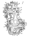
- FIG. 2 is a cross-sectional view showing a configuration of a continuously variable transmission 18 according to an embodiment of the present invention in the vehicle power transmission device 10 of FIG.
- the continuously variable transmission 18 is provided on an outer peripheral side of the input shaft 34, and an input shaft 34 that is rotatably supported by a transaxle case 38 around a shaft center C ⁇ b> 1 via a pair of bearings 42.
- the secondary pulley (groove width variable pulley) 52 provided on the outer peripheral side of the shaft 34 and the primary pulley 46 and the V-groove 54 of the secondary pulley 52 are wound around the pulley 34 so that power is transmitted by friction between the pulleys.
- a known endless annular transmission belt 56 is used to transmit a known endless annular transmission belt 56.
- the primary pulley 46 is relatively non-rotatable with respect to the input shaft 34 so that the V groove 54 is formed between the fixed sheave 58 fixed on the outer peripheral side of the input shaft 34 and the fixed sheave 58, and the input thereof
- the movable sheave 60 provided so as to be relatively movable in the direction of the axis C1 of the shaft 34, and the movable sheave 60 and the fixed sheave 58 are moved closer to each other by moving the movable sheave 60 in the direction of the axis C1 according to the supplied hydraulic pressure.
- a hydraulic actuator 62 that changes the groove width of the V-groove 54 by being separated.
- the secondary pulley 52 is not relatively rotatable with respect to the output shaft 50 so as to form the V groove 54 between the fixed sheave 64 fixed to the outer peripheral side of the output shaft 50 and the fixed sheave 64.
- a movable sheave 66 provided so as to be relatively movable in the direction of the axis C2 of the output shaft 50, and the movable sheave 66 and the fixed sheave 64 are moved in the direction of the axis C2 in accordance with the supplied hydraulic pressure.
- a hydraulic actuator 68 that changes the groove width of the V-groove 54 by approaching or separating.
- the hydraulic actuator 68 of the secondary pulley 52 is a single piston type, whereas the hydraulic actuator 62 of the primary pulley 46 is a double piston type, and the hydraulic pressure of the secondary pulley 52 is
- the actuator 68 is provided with a coil spring 70 that always urges the movable sheave 66 toward the fixed sheave 64 side, whereas the hydraulic actuator 62 of the primary pulley 46 is not provided with a spring as described above. Is a variable groove width pulley having a similar structure.
- the secondary pulley 52 is demonstrated in detail on behalf of the primary pulley 46 and the secondary pulley 52. FIG.
- the fixed sheave 64 is an annular plate-like member that protrudes from the outer peripheral surface of the output shaft 50 to the outer peripheral side and is provided integrally with the output shaft 50.
- the fixed sheave 64 is formed with a tapered surface 72 that is separated from the movable sheave 60 toward the outer peripheral side on the surface facing the movable sheave 60.
- the movable sheave 66 is engaged with the output shaft 50 by a ball spline method so as to be relatively movable in the direction of the axis C2 and non-rotatably around the axis C2, and to fix the cylindrical part 66a.
- a circular plate-like member that is integrally provided so as to protrude from one end portion on the sheave 64 side toward the outer peripheral side, and has a tapered surface 74 that is separated from the fixed sheave 64 toward the outer peripheral side on the surface facing the fixed sheave 64. It has a plate portion 66b and an outer cylindrical portion 66c projecting in the direction of the axis C2 from the outer peripheral portion of the disk portion 66b toward the opposite side of the fixed sheave 64.
- the tapered surface 74 and the tapered surface 72 of the fixed sheave 64 form a V-shaped V groove 54.
- the hydraulic actuator 68 has an inner peripheral wall portion having an inner peripheral portion sandwiched between a stepped end surface of one end portion thereof and the bearing 48 at one end portion of the output shaft 50 opposite to the fixed sheave 64 with respect to the movable sheave 66.
- a cylinder member 76 having an outer peripheral wall portion 76 c that protrudes on the outer peripheral side and slides through an oil seal with respect to the inner peripheral surface of the outer cylindrical portion 66 c of the movable sheave 66 is provided.
- a hydraulic chamber 78 is formed in a space that is oil-tightly surrounded by the cylinder member 76, the movable sheave 66, and the output shaft 50.
- the hydraulic chamber 78 includes a first oil passage 80 and an output shaft 50 that are formed in the transaxle case 38 and are supplied with hydraulic pressure via a hydraulic control device (not shown) that regulates the hydraulic pressure generated by the oil pump 28.
- Hydraulic pressure is supplied through a second oil passage 82 formed on the inner peripheral side and a third oil passage 84 formed through the output shaft 50 in the radial direction.
- the coil spring 70 is located between the stepped end surface formed on the outer peripheral surface of the inner cylindrical portion 66a of the movable sheave 66 and the stepped end surface formed on the inner peripheral surface of the cylindrical portion 76b of the cylinder member 76. Is provided.
- the movable sheave 66 approaches or separates from the fixed sheave 64 in the direction of the axis C1 in accordance with the hydraulic pressure supplied to the hydraulic chamber 78, so that the width of the V groove 54 changes.
- the movable sheave 66 indicated by a solid line below the axis C ⁇ b> 1 shows a state in which the V groove 54 formed between the fixed sheave 64 and the minimum sheave has a minimum width. In this state, the engagement diameter of the transmission belt 56 is maximized.
- a movable sheave 66 indicated by a solid line on the upper side of the axis C1 and indicated by a two-dot chain line on the lower side shows a state in which the V groove 54 formed between the fixed sheave 64 and the fixed sheave 64 has a maximum width. In this state, the diameter of the transmission belt 56 is minimized.
- FIG. 3 is an enlarged cross-sectional view of the secondary pulley 52 and one end of the output shaft 50 in the continuously variable transmission 18 of FIG.
- a parking gear 86 for fixing the output shaft 50 so as not to rotate is fixed between the secondary pulley 52 of the output shaft 50 and the bearing 48.
- the parking gear 86 is fixed to the fixed sheave 64 on the side opposite to the movable sheave 66 by a disc-like main body 86a fixed by, for example, spline fitting to the output shaft 50, and the main body 86a.
- the sheave 64 has an annular protrusion 86b that protrudes toward the surface opposite to the movable sheave 66, that is, the rear surface 90, and abuts at a radial position corresponding to the maximum engagement diameter of the transmission belt 56 in the rear surface 90. Yes.
- outer peripheral teeth 88 that can be engaged with a parking pole (not shown) provided on a non-rotating member such as the transaxle case 38 are formed.
- the output shaft 50 is fixed to be non-rotatable about the axis C2 when the parking pole is engaged with the outer peripheral teeth 88 of the parking gear 86.
- the parking gear 86 has a main body portion 86a fitted into one end portion of the output shaft 50, for example, in an interference fit or a clearance fit, and is sandwiched between the bearing 48 and the fixed sheave 64 in the direction of the axis C2.
- the nut 92 screwed into the shaft end portion of the output shaft 50 is tightened on the opposite side of the bearing 48 from the bearing 48, whereby the shaft 46 is moved in the direction of the axis C2 between the bearing 46 and the fixed sheave 64. It is pinched.
- a pressing force (preload) from the annular protrusion 86b of the parking gear 86 toward the fixed sheave 64 is given to the fixed sheave 64 in advance.
- This pressing force is adjusted to a predetermined value by adjusting the tightening torque according to the relationship between the tightening torque of the nut 92 and the pressing force, which are experimentally determined in advance.
- the predetermined value is set as large as possible within a range in which the fixed sheave 64 is not deformed to the movable sheave 66 side.
- the annular protrusion 86b of the parking gear 86 of this embodiment is different from the annular protrusion 104b of the conventional parking gear 104 shown in FIG.
- the primary hydraulic pressure supplied to the hydraulic actuator 62 of the primary pulley 46 is regulated by the hydraulic control device and supplied to the hydraulic actuator 68 of the secondary pulley 52.
- the secondary hydraulic pressure is controlled by the hydraulic control device, the groove widths of the V grooves 54 of the primary pulley 46 and the secondary pulley 52 change, and the clamping pressure with respect to the transmission belt 56 is adjusted.
- the groove width of the V groove 54 of the primary pulley 46 and the secondary pulley 52 changes, the engagement diameter of the transmission belt 56 changes, and the rotational speed ratio (speed change) between the input shaft 34 and the output shaft 50 changes. Ratio) changes steplessly.
- the transmission belt 56 indicated by a solid line has a minimum engagement diameter at the primary pulley 46 and a maximum engagement diameter at the secondary pulley 52.
- the transmission gear ratio of the continuously variable transmission 18 is set to the maximum transmission gear ratio.
- the transmission belt 56 indicated by a two-dot chain line has a maximum engagement diameter at the primary pulley 46 and a minimum engagement diameter at the secondary pulley 52, and the belt type continuously variable transmission 18. The state where the gear ratio is set to the minimum gear ratio is shown.
- the fixed sheave 64 and the movable sheave 66 of the secondary pulley 52 receive a reaction force from the transmission belt 56 while applying a clamping pressure in the direction of the axis C2 to the transmission belt 56.
- the fixed sheave 64 is fixed to the fixed sheave 64 with the base side of the fixed sheave 64 as a fulcrum by the axial reaction force Fc2 of the axial center C2 component of the reaction force F received from the transmission belt 56.
- a moment M is applied to tilt the sway to the opposite side of the movable sheave 66.
- the reaction force and the moment M are maximized when the engagement diameter of the transmission belt 56 is maximized as shown by the solid line in FIG.
- the parking gear 86 is in contact with the back surface 90 of the fixed sheave 64 on the side where the fixed sheave 64 is about to fall due to the moment M.
- the pressing force acting in the direction opposite to the axial reaction force Fc2 is applied to the fixed sheave 64 in advance.
- the pressing force is applied to a position of the back surface 90 of the fixed sheave 64 that opposes the operating point of the maximum axial reaction force Fc2 that the fixed sheave 64 receives from the transmission belt 56 in the operating direction. It has become. Therefore, the parking gear 86 of this embodiment functions as a member that supports the fixed sheave 64 so as to resist the axial reaction force Fc2 (bending moment M).
- the secondary pulley (groove width variable pulley) 52 includes a fixed sheave 64 fixed to the outer peripheral surface of the output shaft 50 (one of the input shaft and the output shaft), A movable groove provided on the output shaft 50 so as not to be relatively rotatable about the axis C2 and to be relatively movable in the direction of the axis C2 so as to form a V-groove 54 for sandwiching the transmission belt 56 with the fixed sheave 64.
- the annular protrusion 8 protrudes from 86a toward the surface opposite to the movable sheave 66 of the fixed sheave 64, that is, the back surface 90, and abuts at the radial position corresponding to the maximum engagement diameter of the transmission belt 56 on the back surface 90. Since the transmission gear 56 is clamped between the fixed sheave 64 and the movable sheave 66, the fixed sheave 64 is moved from the transmission belt 56 to the axial center direction C2.
- the annular protrusion 86 b of the parking gear 86 abuts on the radial position corresponding to the maximum engagement diameter of the transmission belt 56 on the back surface 90 of the fixed sheave 64.
- the fixed sheave 64 receives the maximum axial reaction force Fc2 in the axial center C2 direction from the transmission belt 56 by sandwiching the transmission belt 56 positioned at the maximum engagement diameter between the fixed sheave 64 and the movable sheave 66.
- the parking gear 86 is tightened with the nut 92 screwed to the shaft end portion of the output shaft 50 and tightened with the fixed sheave 64 in the axial center C2 direction.
- the fixed sheave 64 is preliminarily applied with a pressing force (preload) from the parking gear 86 to the fixed sheave 64 side in a direction opposite to the axial reaction force Fc2. Even if the axial sheer reaction force Fc2 to the parking gear 86 side acts on the fixed sheave 64, it is possible to suitably suppress the fall.
- the pressing force previously applied from the parking gear 86 to the fixed sheave 64 is as large as possible within a range in which the fixed sheave 64 does not deform toward the movable sheave 66 side. Therefore, the stationary sheave 64 can be prevented from falling down while preventing the fixed sheave 64 from being deformed to the movable sheave 66 side by the pressing force and lowering the power transmission efficiency.
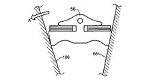
- FIG. 8 is a cross-sectional view showing the secondary pulley 102 and the parking gear 104 in the conventional continuously variable transmission 100 and corresponds to FIG. 3 of the first embodiment.
- the annular protrusion 104 b has a radial position on the inner peripheral side of the base portion of the fixed sheave 106, that is, the minimum engagement diameter of the transmission belt 56 in the back surface 108 of the fixed sheave 106. It is in contact with.
- the continuously variable transmission 18 of the present embodiment since the back surface 90 of the fixed sheave 464 is supported by the annular protrusion 86b of the parking gear 86, the conventional fixed shown by a two-dot chain line in FIG. Even if the thickness of the fixed sheave 64 in the direction of the axis C2 is smaller than that of the sheave 106, the fixed sheave 64 can be prevented from falling. Therefore, compared to the conventional continuously variable transmission 100, the material cost of the fixed sheave 64 is reduced, the manufacturing cost of the continuously variable transmission 18 is reduced, and the weight of the continuously variable transmission 18 is reduced.
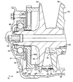
- FIG. 4 is an enlarged sectional view showing the secondary pulley 202 and the parking gear 204 in the continuously variable transmission 200 according to another embodiment of the present invention.
- the fixed sheave 206 of the secondary pulley 202 includes an annular fitting portion 206 a that protrudes from the outer peripheral portion of the back surface 208 on the side opposite to the movable sheave 66 toward the parking gear 204.
- the parking gear 204 is an annular plate-shaped main body portion 204 a fixed to the outer peripheral surface of the output shaft 50, and protrudes from the main body portion 204 a toward the fixed sheave 206. And an annular protrusion 204b fitted in 206a and engaged in the radial direction.
- the parking gear 204 has a main body portion 204a fitted into one end portion of the output shaft 50, for example, in an interference fit or a clearance fit, and is sandwiched between the bearing 48 and the fixed sheave 206 in the axial center C2 direction.
- the nut 92 screwed to the shaft end portion of the output shaft 50 is tightened on the opposite side of the bearing 48 from the parking gear 204, so that the shaft 46 moves in the direction of the axis C2 between the bearing 46 and the fixed sheave 206. It is pinched.
- a pressing force (preload) from the parking gear 204 toward the fixed sheave 206 is applied to the fixed sheave 206.
- This pressing force is adjusted to a predetermined value by adjusting the tightening torque according to the relationship between the tightening torque of the nut 92 and the pressing force, which are experimentally determined in advance.
- the predetermined value is set as large as possible within a range in which the fixed sheave 206 is not deformed to the movable sheave 66 side.
- the pressing force is applied in advance from the parking gear 204 to the fixed sheave 206 by tightening the nut 92 screwed to the shaft end of the output shaft 50. The same applies to each of the parking gears, and the description thereof is omitted in the following embodiments.
- the fixed sheave 206 is opposite to the movable sheave 66 with the base portion, that is, the inner peripheral portion of the fixed sheave 206 as a fulcrum by the axial reaction force Fc2 received from the transmission belt 56.
- a moment M that tends to tilt to the side acts on the fixed sheave 206.
- the parking gear 204 is in contact with the back surface 208 of the fixed sheave 206 on the side where the fixed sheave 206 is about to fall due to the moment M.
- the pressing force acting in the direction opposite to the axial reaction force Fc2 is applied to the fixed sheave 206 in advance.
- the pressing force is applied to a position of the back surface 208 of the fixed sheave 206 that opposes the operating point of the maximum axial reaction force Fc2 that the fixed sheave 206 receives from the transmission belt 56 in the direction of the operation. It has become. Therefore, the parking gear 204 of this embodiment functions as a member that supports the fixed sheave 206 so as to resist the axial reaction force Fc2 (bending moment M).
- the parking gear 204 of the present embodiment is a member that supports the stationary sheave 206 in the radial direction so that the stationary sheave 206 does not fall against the radial reaction force Fr of the direction component orthogonal to the axis C2 of the reaction force F. Function.
- a disc-shaped main body portion 204a fixed to the output shaft 50 on the opposite side of the fixed sheave 206 from the movable sheave 66, a disc-shaped main body portion 204a fixed to the output shaft 50, and the main body portion 204a. Parking having an annular protrusion 204b that protrudes toward a surface opposite to the movable sheave 66 of the fixed sheave 206, that is, a rear surface 208, and abuts at a radial position corresponding to the maximum engagement diameter of the transmission belt 56 on the rear surface 208.
- the fixed sheave 206 Since the gear 204 is provided, the fixed sheave 206 has the maximum in the direction of the axis C2 from the transmission belt 56 by sandwiching the transmission belt 56 positioned at the maximum engagement diameter between the fixed sheave 206 and the movable sheave 66. Even when the axial reaction force Fc2 is received, the axial direction of the back surface 208 of the fixed sheave 206 with respect to the point of application of the maximum axial reaction force Fc2 Since the position of the acting direction of the force Fc2 is supported by the annular protrusion 204b of the parking gear 204, the falling of the fixed sheave 206 can be suppressed without adding any parts and with a relatively simple configuration as in the first embodiment. can do.
- the annular protrusion 204b of the parking gear 204 is located on the side opposite to the movable sheave 66 of the fixed sheave 206, that is, from the outer periphery of the back surface 208 toward the parking gear 204.
- the fixed sheave 206 is inserted into the projecting annular fitting portion 206 a and engaged in the radial direction, so that the fixed sheave 206 is transmitted by clamping the transmission belt 56 between the fixed sheave 206 and the movable sheave 66.
- the radial reaction force Fr in the direction orthogonal to the axis C2 received from the belt 56 is transmitted to the output shaft 50 through the fixed sheave 206 and the parking gear 204, and the radial reaction force Fr is transmitted only through the fixed sheave 206.
- it since it is distributed and applied in the direction of the axis C2, it is possible to suitably suppress the bending of the output shaft 50 due to the radial reaction force Fr.
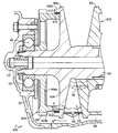
- FIG. 5 is an enlarged sectional view showing the secondary pulley 302 and the parking gear 304 in the continuously variable transmission 300 according to another embodiment of the present invention.
- a stepped end surface 310 is formed on the fixed sheave 306 of the secondary pulley 302 on the inner peripheral portion of the back surface 308 opposite to the movable sheave 66.
- the parking gear 304 includes a main body 304a and an annular protrusion 304b similar to the main body 86a and the annular protrusion 86b of the parking gear 86 of the first embodiment, and an inner peripheral side of the annular protrusion 304b of the main body 304a.
- a stopper portion 304c protruding toward the stepped end surface 310 of the back surface 308.
- the stopper portion 304c comes into contact with the stepped end surface 310 of the back surface 308, and the annular projection 304b.
- the application of the pressing force to the fixed sheave 306 is limited.
- the predetermined value is set as large as possible within a range in which the fixed sheave 306 is not deformed to the movable sheave 66 side.
- FIG. 5 shows a state in which a gap in the direction of the axis C2 is formed between the stopper portion 304c and the stepped end surface 310. This indicates a stage in the middle of assembly, Actually, the stopper portion 304c and the stepped end surface 310 are brought into contact with each other in the axial center C2 direction, and a predetermined pressing force of a predetermined value is applied from the annular protrusion 304b to the fixed sheave 306 as described above.
- the parking gear 304 is a member that supports the fixed sheave 306 so as to resist the axial reaction force Fc2 (bending moment M). Function.
- the fixed sheave 306 has a relatively simple configuration without adding parts. The fall can be suppressed.
- the parking gear 304 is provided with a stopper portion 304c that protrudes from the inner peripheral side of the annular protrusion 304b of the main body portion 304a toward the stepped end surface 310 of the back surface 308.
- the stopper portion 304c comes into contact with the stepped end surface 310 of the back surface 308, and the annular projection Since the application of the pressing force from 304b to the fixed sheave 306 is limited, if the parking gear 304 is fixed at a position where the stopper portion 304c abuts the stepped end surface 310 of the back surface 308, the parking gear 304 is fixed to the fixed sheave 306 beforehand. Since the applied pressing force (preload) can be made uniform, the above pressing force can be adjusted easily. . That is, the pressing force can be adjusted by, for example, human work without using a special device such as a preload adjusting device.
- the parking gear 304 is clamped in the direction of the axis C2 with the fixed sheave 306 by tightening the nut 92 screwed to the shaft end portion of the output shaft 50 to which the parking gear 304 is fixed.
- the parking gear 304 is Since the pressing force to the fixed sheave 306 can be given a predetermined value, the pressing force can be easily adjusted.
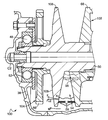
- FIG. 6 is an enlarged sectional view showing the secondary pulley 402 and the parking gear 404 in the continuously variable transmission 400 according to another embodiment of the present invention.
- the fixed sheave 406 of the secondary pulley 402 has an axial center at a portion including the radial position corresponding to the maximum engagement diameter of the transmission belt 56 on the outer peripheral portion of the back surface 408 opposite to the movable sheave 66.
- a plurality of first spline teeth (engagement teeth) 410 extending radially from the center of C2 are formed continuously in the circumferential direction.
- the first spline teeth 410 of this embodiment are involute splines, for example, but may be other splines.
- the parking gear 404 protrudes toward the back surface 408 of the fixed sheave 406 from the main body portion 404a similar to the main body portion 86a of the parking gear 86 of the first embodiment. And an annular protrusion 404b that contacts the fixed sheave 406 at a radial position corresponding to the maximum engagement diameter.
- the parking gear 404 is formed in a fixed sheave via a plurality of second spline teeth 412 that are respectively formed radially at the front end of the annular protrusion 404b and centered on the axis C2 and mesh with the plurality of first spline teeth 410, respectively.
- 406 is in contact with the axis C2 and engaged in the circumferential direction.
- the parking gear 404 is a member that supports the fixed sheave 406 so as to resist the axial reaction force Fc2 (bending moment M). Function.
- the engaging portion between the first spline teeth 410 and the second spline teeth 412 is used.
- the torque of the output shaft 50 is transmitted to the parking gear 404.
- the length L in the axial center C2 direction of the spline fitting portion between the outer peripheral surface of the output shaft 50 and the inner peripheral surface of the parking gear 404 of this embodiment is shortened by the length L1.
- the fixed sheave 406 can be formed without adding parts and with a relatively simple configuration as in the first embodiment. The fall can be suppressed.
- the annular protrusion 404b of the parking gear 404 has a surface opposite to the movable sheave 66 of the fixed sheave 406, that is, the back surface 408 via the second spline teeth 412. Since the first spline teeth (engagement teeth) 410 formed in the outer peripheral portion of the parking gear 404 are engaged in the circumferential direction, the parking gear 404 is fixed to the outer peripheral teeth 88 of the parking gear 404 in order to fix the output shaft 50 in a non-rotatable manner.
- the reaction force that is, the torque that the parking gear 404 receives from the parking pole due to the engagement of the pawl is the engaging portion between the parking gear 404 and the fixed sheave 406 in addition to the engaging portion between the parking gear 404 and the output shaft 50. Therefore, even if the length L of the engagement portion between the parking gear 404 and the output shaft 50 is shortened in the direction of the axis C2, the parking The strength to resist the reaction force received from Lumpur can be secured to a conventional equal to or higher. Further, the engaging portion between the first spline teeth 410 and the second spline teeth 412 is provided on the outer peripheral side than the spline fitting portion between the outer peripheral surface of the output shaft 50 and the inner peripheral surface of the parking gear 404.
- the strength for resisting the reaction force received from the parking pole can be suitably ensured to be equal to or higher than the conventional one. Therefore, the molding cost of the spline fitting portion between the outer peripheral surface of the output shaft 50 and the inner peripheral surface of the parking gear 404 is reduced, and the length of the output shaft 50 is shortened by the shortened length L1 of the spline fitting portion. Therefore, the manufacturing cost of the continuously variable transmission 400 can be reduced.
- FIG. 7 is an enlarged cross-sectional view of the secondary pulley 502 and the parking gear 504 in the continuously variable transmission 500 according to another embodiment of the present invention.
- the fixed sheave 506 of the secondary pulley 502 includes an annular fitting portion 506 a that protrudes from the outer peripheral portion of the back surface 508 opposite to the movable sheave 66 toward the fixed sheave 506.
- a plurality of first spline teeth (engagement teeth) 510 extending in the axial center C2 direction are formed on the inner peripheral surface of the portion 506a in a circumferential direction.
- the first spline teeth 510 of the present embodiment are, for example, involute splines, but may be other splines.
- the parking gear 504 protrudes from the main body 504a toward the rear surface 508 of the fixed sheave 506, and the rear surface of the main body 504a.
- the main body 504a has an inner peripheral surface fitted on the outer peripheral surface of the output shaft 50.
- An annular protrusion 504 b that abuts against the fixed sheave 506 at a radial position corresponding to the maximum engagement diameter of the transmission belt 56 out of 508.
- the parking gear 504 is fixed to the fixed sheave via a plurality of second spline teeth 512 that extend in the direction of the axis C2 on the outer peripheral surface of the tip of the annular protrusion 504b and mesh with the plurality of first spline teeth 510, respectively. 506 is engaged in the circumferential direction.
- the parking gear 504 is a member that supports the fixed sheave 506 so as to resist the axial reaction force Fc2 (bending moment M). Function. Even if the parking gear 504 receives a moment that tends to fall to the opposite side of the movable sheave 66 due to the reaction force F that the fixed sheave 506 receives from the transmission belt 56, the annular protrusion 204 b of the parking gear 504 does not move. The annular fitting portion 506a of the fixed sheave 206 is supported in the radial direction on the side to be tilted.
- the parking gear 504 of this embodiment is a member that supports the stationary sheave 506 in the radial direction so that the stationary sheave 506 does not fall against the radial reaction force Fr of the directional component orthogonal to the axis C2 of the reaction force F. Function.
- the torque of the output shaft 50 is transmitted to the parking gear 504 through the engaging portion between the first spline teeth 510 and the second spline teeth 512.
- the engagement portion between the first spline teeth 410 and the second spline teeth 412 is a spline fitting portion between the outer peripheral surface of the output shaft 50 and the inner peripheral surface of the parking gear 104 formed in the conventional one shown in FIG.
- the parking pawl is engaged with the outer peripheral teeth 88 of the parking gear 504 in order to fix the output shaft 50 in a non-rotatable manner, so that the parking gear 504 receives the reaction force received from the parking pawl.
- the strength to withstand is ensured to be equal to or higher than the conventional one.
- the configuration other than the above is the same as that of the first embodiment, and according to the continuously variable transmission 500 of the present embodiment, as in the first embodiment, the fixed sheave 506 can be formed without adding parts and with a relatively simple configuration. The fall can be suppressed.
- the annular protrusion 504b of the parking gear 504 has a surface opposite to the movable sheave 66 of the fixed sheave 506, that is, the back surface 508 via the second spline teeth 512. Since the first spline teeth (engagement teeth) 510 formed on the outer peripheral portion of the outer peripheral portion are engaged in the circumferential direction, the conventionally provided spline fitting portion between the parking gear 504 and the output shaft 50 is eliminated. be able to.
- the engaging portion between the first spline teeth 410 and the second spline teeth 412 is a spline fitting between the outer peripheral surface of the output shaft 50 and the inner peripheral surface of the parking gear 104 formed in the conventional one shown in FIG. Since the parking pawl is engaged with the outer peripheral teeth 88 of the parking gear 504 in order to fix the output shaft 50 so as not to rotate, the reaction force received by the parking gear 504 from the parking pawl is provided. The strength for resisting the above can be ensured to be equal to or higher than the conventional one.
- annular protrusion 204b of the parking gear 504 supports the annular fitting portion 506a of the fixed sheave 206 in the radial direction, the bending rigidity of the output shaft 50 and the entire member fixed thereto is improved. Enhanced. Therefore, even if the diameter of the output shaft 50 is reduced, it is possible to ensure a bending rigidity equal to or higher than the conventional one.
- the parking gear 86 (204, 304, 404, 504) is provided on the secondary pulley 52 (202, 302, 402, 502), but may be provided on the primary pulley 46 provided on the input shaft. .
- the parking gear 86 (204, 304, 404, 504) has an axis C2 between the nut 92 and the fixed sheave 64 (206, 306, 406, 506).
- the pressing force from the parking gear 86 to the fixed sheave 64 has been applied in advance, but this pressing force does not necessarily have to be applied. Even when the pressing force is applied, the pressing force may not necessarily be as large as possible as long as the fixed sheave 64 is not deformed to the movable sheave 66 side.
- Vehicle continuously variable transmission 34 Input shaft 46: Primary pulley (variable groove width pulley) 50: Output shaft (one of input shaft and output shaft) 52, 202, 302, 402, 502: secondary pulley (variable groove width pulley) 54: V groove 56: Transmission belt 64, 206, 306, 406, 506: Fixed sheave 66: Movable sheave 86, 204, 304, 404, 504: Parking gear 86a, 204a, 304a, 404a, 504a: Main body 86b, 204b, 304b, 404b, 504b: annular projection 304c: stopper portions 90, 208, 308, 408, 508: back surface (surface opposite to the movable sheave of the fixed sheave) 92: Nuts 410, 510: First spline teeth (engagement teeth)
Abstract
Provided is a belt type stepless transmission for a vehicle, configured in such a manner that a fixed sheave is prevented from tilting.
A belt type stepless transmission for a vehicle comprises a parking gear (86) provided on the opposite side of a fixed sheave (64) from a movable sheave (66), and the parking gear (86) is provided with: a circular plate-like body section (86a) secured to an output shaft (50) by being, for example, engaged therewith through splines; and an annular ridge section (86b) which protrudes from the body section (86a) toward the rear surface (90) of the fixed sheave (64), said rear surface (90) being located on the opposite side of the movable sheave (66), and makes contact with the rear surface (90) at the radial position corresponding to the maximum engagement diameter of a power transmitting belt (56). The configuration enables, even if the fixed sheave (64) is subjected to an axial reaction force (Fc2) acting in the axis (C2) direction and applied from the power transmitting belt (56), the parking gear (86), which is formed by applying only a relatively simple change to a conventional product, to support the fixed sheave (64) at the rear surface (90) thereof at a position more toward the outer peripheral side than the minimum engaging diameter of the power transmitting belt (56). As a result, the fixed sheave (64) is prevented from tilting.
Description
本発明は、車両用ベルト式無段変速機に関し、特に、固定シーブの倒れを抑制するための技術に関するものである。
The present invention relates to a belt-type continuously variable transmission for a vehicle, and more particularly to a technique for suppressing the falling of a fixed sheave.
互いに平行に設けられた入力軸および出力軸と、その入力軸および出力軸の外周側に設けられた一対の溝幅可変プーリと、その一対の溝幅可変プーリのV溝にそれぞれ巻き掛けられた伝動ベルトとを備え、そのV溝の溝幅を変化させて前記伝動ベルトの掛かり径を変化させることにより変速比を無段階に変化させる車両用ベルト式無段変速機が知られている。例えば、特許文献1乃至5に記載されたものがそれである。
An input shaft and an output shaft provided in parallel to each other, a pair of variable groove width pulleys provided on the outer peripheral side of the input shaft and the output shaft, and a V groove of the pair of variable groove width pulleys, respectively. 2. Description of the Related Art There is known a vehicular belt type continuously variable transmission that includes a transmission belt and changes a gear ratio steplessly by changing a groove width of the transmission belt by changing a groove width of the V groove. For example, those described in Patent Documents 1 to 5.
ところで、特許文献1乃至3の溝幅可変プーリは、回転軸に固設された固定シーブと、その固定シーブとの間にV溝を形成するようにその回転軸に軸心方向の移動可能且つ軸心まわりの相対回転不能に設けられた可動シーブとを備え、その固定シーブと可動シーブとの間で前記伝動ベルトを挟圧するようになっている。このとき、固定シーブには、伝動ベルトから受ける反力のうち軸心方向の力に起因して、固定シーブの基部すなわち内周部を支点としてその固定シーブを伝動ベルトとは反対側に倒そうとするモーメントが作用する。そのため、従来のベルト式無段変速機では、固定シーブが可動シーブとは反対側へ倒れる方向の変形に起因して、その固定シーブと伝動ベルトとの接触面積が減少して伝達トルクが低下するという問題があった。この問題に対しては、例えば固定シーブの軸心方向の厚みを大きくして強度を高めることで対処されていたが、これによれば、無段変速機の製造コストが増加すると共に重量が増加するという欠点があった。
By the way, the variable groove width pulleys of Patent Documents 1 to 3 are movable in the axial direction on the rotary shaft so as to form a V-groove between the fixed sheave fixed to the rotary shaft and the fixed sheave. And a movable sheave provided around the shaft so as not to rotate relative to the shaft. The transmission belt is clamped between the fixed sheave and the movable sheave. At this time, due to the axial force in the reaction force received from the transmission belt, the fixed sheave will be tilted to the opposite side of the transmission belt with the base portion of the fixed sheave, that is, the inner periphery as a fulcrum. The moment is applied. Therefore, in the conventional belt-type continuously variable transmission, the contact area between the fixed sheave and the transmission belt is reduced due to the deformation in the direction in which the fixed sheave falls to the opposite side of the movable sheave, and the transmission torque is reduced. There was a problem. This problem has been addressed, for example, by increasing the thickness of the fixed sheave in the axial direction to increase the strength, but according to this, the manufacturing cost of the continuously variable transmission increases and the weight increases. There was a drawback of doing.
これに対して、例えば、特許文献4には、前記反力に抗するために、固定シーブを可動シーブとは反対側から付勢する弾性部材たとえば皿ばねが記載されている。しかし、これによれば、部品すなわち上記弾性部材およびそれを支持する軸受を新たに追加する必要があり、部品点数が増加するという欠点があった。特許文献5には、前記反力に抗するために、固定シーブの可動シーブとは反対側の面に隣接して油室を形成して、その油室に油圧を供給することが記載されている。しかし、これによれば、構成が複雑となるとともに、上記油室を形成するための部材およびその油室に油圧を供給するための油路を追加する等の部品の大幅な変更が必要であるという欠点があった。
On the other hand, for example, Patent Document 4 describes an elastic member such as a disc spring that urges the fixed sheave from the side opposite to the movable sheave to resist the reaction force. However, according to this, it is necessary to newly add a component, that is, the elastic member and a bearing for supporting the component, and there is a disadvantage that the number of components increases. Patent Document 5 describes that in order to resist the reaction force, an oil chamber is formed adjacent to the surface of the fixed sheave opposite to the movable sheave and hydraulic pressure is supplied to the oil chamber. Yes. However, this complicates the configuration and requires significant changes in parts such as adding a member for forming the oil chamber and an oil passage for supplying hydraulic pressure to the oil chamber. There was a drawback.
本発明は以上の事情を背景としてなされたものであり、その目的とするところは、部品を追加することなく固定シーブの倒れを抑制することができる車両用ベルト式無段変速機を提供することにある。
The present invention has been made against the background of the above circumstances, and an object of the present invention is to provide a belt type continuously variable transmission for a vehicle that can suppress the falling of a fixed sheave without adding parts. It is in.
かかる目的を達成するための請求項1にかかる発明の要旨とするところは、(a) 互いに平行に設けられた入力軸および出力軸と、その入力軸および出力軸の外周側に設けられた一対の溝幅可変プーリと、その一対の溝幅可変プーリのV溝にそれぞれ巻き掛けられた伝動ベルトとを備え、そのV溝の溝幅を変化させて前記伝動ベルトの掛かり径を変化させることにより変速比を無段階に変化させる車両用ベルト式無段変速機であって、(b) 前記溝幅可変プーリは、前記入力軸および出力軸の一方の外周面に固設された固定シーブと、その固定シーブとの間に前記V溝を形成するように、前記一方の軸に相対回転不能且つその一方の軸の軸心方向に相対移動可能に設けられた可動シーブとを備えるものであり、(c) 前記固定シーブに対して前記可動シーブとは反対側において、前記一方の軸に固設された円板状の本体部と、その本体部から前記固定シーブの前記可動シーブとは反対側の面に向けて突き出し、その反対側の面のうち前記伝動ベルトの最小掛かり径よりも外周側で当接する環状突部とを有するパーキングギヤが設けられていることにある。
The gist of the invention according to claim 1 for achieving this object is that: (a) an input shaft and an output shaft provided in parallel with each other, and a pair provided on the outer peripheral side of the input shaft and the output shaft And a transmission belt wound around each of the V-grooves of the pair of variable-width pulleys, and changing the groove width of the V-groove to change the engagement diameter of the transmission belt. A belt-type continuously variable transmission for a vehicle that continuously changes a gear ratio, wherein (b) the groove width variable pulley includes a fixed sheave fixed to one outer peripheral surface of the input shaft and the output shaft; A movable sheave provided so as to be relatively non-rotatable on the one shaft and relatively movable in the axial direction of the one shaft so as to form the V-groove between the fixed sheave, (c) 可 For the fixed sheave On the opposite side of the sheave, a disc-shaped main body fixed to the one shaft, and projecting from the main body toward the surface of the fixed sheave opposite to the movable sheave, The parking gear which has an annular protrusion which contact | abuts on the outer peripheral side rather than the minimum hook diameter of the said transmission belt is provided in the surface.
また、請求項2にかかる発明の要旨とするところは、請求項1にかかる発明において、前記パーキングギヤの環状突部は、前記固定シーブの前記可動シーブとは反対側の面のうち、前記伝動ベルトの最大掛かり径に対応する径方向位置に当接することにある。
The gist of the invention according to claim 2 is that, in the invention according to claim 1, the annular protrusion of the parking gear is configured such that the transmission of the fixed sheave on the side opposite to the movable sheave is the transmission. It is in contact with the radial position corresponding to the maximum hook diameter of the belt.
また、請求項3にかかる発明の要旨とするところは、請求項1または2にかかる発明において、前記パーキングギヤの環状突部は、前記出力軸に設けられた溝幅可変プーリの固定シーブの前記可動シーブとは反対側の面に当接することにある。
The gist of the invention according to claim 3 is that, in the invention according to claim 1 or 2, the annular protrusion of the parking gear is the fixed sheave of the variable groove width pulley provided on the output shaft. It is in contact with the surface opposite to the movable sheave.
また、請求項4にかかる発明の要旨とするところは、請求項1乃至3のいずれか1にかかる発明において、前記パーキングギヤの環状突部は、前記固定シーブの前記可動シーブとは反対側の面の外周部から前記パーキングギヤ側に突設された環状嵌合部内に嵌め入れられて径方向に係合されていることにある。
According to a fourth aspect of the present invention, in the invention according to any one of the first to third aspects, the annular protrusion of the parking gear is located on a side opposite to the movable sheave of the fixed sheave. That is, it is inserted into an annular fitting portion projecting from the outer peripheral portion of the surface to the parking gear side and engaged in the radial direction.
また、請求項5にかかる発明の要旨とするところは、請求項1乃至4のいずれか1にかかる発明において、前記パーキングギヤの環状突部は、前記固定シーブの前記可動シーブとは反対側の面の外周部に形成された係合歯と周方向に係合されていることにある。
According to a fifth aspect of the present invention, in the invention according to any one of the first to fourth aspects, the annular protrusion of the parking gear is located on a side opposite to the movable sheave of the fixed sheave. It exists in being engaged with the engaging tooth formed in the outer peripheral part of the surface in the circumferential direction.
また、請求項6にかかる発明の要旨とするところは、請求項1乃至5のいずれか1にかかる発明において、前記パーキングギヤは、前記本体部の前記環状突部の内周側から前記固定シーブの前記可動シーブとは反対側の面に向けて突設されたストッパ部を備え、前記固定シーブに予め与えられる前記環状突部からその固定シーブへの押圧力が予め定められた所定値に達すると前記ストッパ部が前記反対側の面に当接して、前記環状突部から固定シーブへの押圧力の付与を制限することにある。
According to a sixth aspect of the present invention, there is provided the invention according to any one of the first to fifth aspects, wherein the parking gear is arranged on the fixed sheave from an inner peripheral side of the annular protrusion of the main body. A stopper portion projecting toward a surface opposite to the movable sheave of the movable sheave, and the pressing force to the fixed sheave from the annular projection previously applied to the fixed sheave reaches a predetermined value. Then, the stopper part comes into contact with the surface on the opposite side to limit the application of the pressing force from the annular protrusion to the fixed sheave.
また、請求項7にかかる発明の要旨とするところは、請求項請求項1乃至6のいずれか1にかかる発明において、前記パーキングギヤは、前記一方の軸の軸端部に螺合されたナットによって締め付けられることで前記固定シーブとの間で軸心方向に挟圧されることにある。
The gist of the invention according to claim 7 is that, in the invention according to any one of claims 1 to 6, the parking gear is a nut screwed to the shaft end portion of the one shaft. By being tightened by the screw, the pressure is clamped in the axial direction between the fixed sheave.
請求項1にかかる発明の車両用ベルト式無段変速機によれば、溝幅可変プーリは、入力軸および出力軸の一方の外周面に固設された固定シーブと、その固定シーブとの間に伝動ベルトを挟持するためのV溝を形成するように、前記一方の軸に相対回転不能且つその一方の軸の軸心方向に相対移動可能に設けられた可動シーブとを備えるものであり、固定シーブに対して可動シーブとは反対側において、前記一方の軸に固設された円板状の本体部と、その本体部から固定シーブの可動シーブとは反対側の面に向けて突き出し、その反対側の面のうち伝動ベルトの最小掛かり径よりも外周側で当接する環状突部とを有するパーキングギヤが設けられていることから、固定シーブと可動シーブとの間で伝動ベルトを挟圧することで固定シーブが伝動ベルトから軸心方向の反力を受けても、従来から用いられるパーキングギヤに対して前記環状突部を形成するという比較的簡易な変更のみが加えられたことによって、固定シーブの伝動ベルトとは反対側の面のうち伝動ベルトの最小掛かり径よりも外周側が支持されるので、部品を追加することなく且つ比較的簡単な構成によって固定シーブの倒れを抑制することができる。
According to the belt type continuously variable transmission for a vehicle according to the first aspect, the groove width variable pulley is formed between the fixed sheave fixed to one outer peripheral surface of the input shaft and the output shaft and the fixed sheave. A movable sheave provided so as to be relatively non-rotatable on the one shaft and relatively movable in the axial direction of the one shaft so as to form a V-groove for holding the transmission belt on the shaft. On the opposite side to the movable sheave with respect to the fixed sheave, the disc-shaped main body fixed to the one shaft, and projecting from the main body toward the surface opposite to the movable sheave of the fixed sheave, Since the parking gear having an annular protrusion that contacts the outer peripheral side of the minimum engagement diameter of the transmission belt is provided on the opposite surface, the transmission belt is pinched between the fixed sheave and the movable sheave. Fixed sheave Even if it receives a reaction force in the axial direction from the belt, only a relatively simple change of forming the annular protrusion on the conventionally used parking gear has been made. Since the outer peripheral side of the opposite surface is supported with respect to the minimum engagement diameter of the transmission belt, it is possible to suppress the falling of the fixed sheave without adding any parts and with a relatively simple configuration.
請求項2にかかる発明の車両用ベルト式無段変速機によれば、パーキングギヤの環状突部は、固定シーブの可動シーブとは反対側の面のうち、伝動ベルトの最大掛かり径に対応する径方向位置に当接することから、固定シーブと可動シーブとの間で最大掛かり径に位置する伝動ベルトを挟圧することで固定シーブが伝動ベルトから軸心方向の最大の反力を受けても、固定シーブの伝動ベルトとは反対側の面のうち、上記最大の反力の作用点に対して軸心方向すなわち上記反力の作用方向の位置が、パーキングギヤの環状突部により支持されるので、固定シーブに最大の反力が作用してもその倒れを好適に抑制することができる。
According to the belt type continuously variable transmission for a vehicle of the second aspect, the annular protrusion of the parking gear corresponds to the maximum engagement diameter of the transmission belt on the surface of the fixed sheave opposite to the movable sheave. Because it contacts the radial position, even if the fixed sheave receives the maximum reaction force in the axial direction from the transmission belt by pinching the transmission belt located at the maximum engagement diameter between the fixed sheave and the movable sheave, Since the surface of the stationary sheave opposite to the transmission belt is supported by the annular protrusion of the parking gear in the axial direction relative to the point of action of the maximum reaction force, that is, the position of the reaction direction of the reaction force. Even if the maximum reaction force acts on the fixed sheave, it is possible to suitably suppress the fall.
請求項3にかかる発明の車両用ベルト式無段変速機によれば、パーキングギヤの環状突部は、出力軸に設けられた溝幅可変プーリの固定シーブの可動シーブとは反対側の面に当接することから、出力軸に固設される固定シーブが伝動ベルトから軸心方向の反力を受けても、従来から出力軸に固設されるパーキングギヤにより固定シーブが支持されるので、部品を追加することなく且つ比較的簡単な構成によって固定シーブの倒れを抑制することができる。
According to the belt type continuously variable transmission for a vehicle according to the third aspect of the present invention, the annular protrusion of the parking gear is on the surface opposite to the movable sheave of the fixed sheave of the groove width variable pulley provided on the output shaft. Since the fixed sheave fixed to the output shaft receives the reaction force in the axial direction from the transmission belt, the fixed sheave is conventionally supported by the parking gear fixed to the output shaft. It is possible to suppress the falling of the fixed sheave without adding a sash and with a relatively simple configuration.
請求項4にかかる発明の車両用ベルト式無段変速機によれば、パーキングギヤの環状突部は、固定シーブの可動シーブとは反対側の面の外周部からパーキングギヤ側に突設された環状嵌合部内に嵌め入れられて径方向に係合されていることから、固定シーブと可動シーブとの間で伝動ベルトを挟圧することで固定シーブが伝動ベルトから軸心に直交する方向の反力を受けても、その反力をパーキングギヤが受けるので、固定シーブの倒れを一層抑制することができる。
According to the belt type continuously variable transmission for a vehicle according to the fourth aspect, the annular protrusion of the parking gear protrudes from the outer peripheral portion of the surface opposite to the movable sheave of the fixed sheave to the parking gear side. Since it is fitted in the annular fitting portion and engaged in the radial direction, the transmission sheave is clamped between the stationary sheave and the movable sheave so that the stationary sheave is in the direction perpendicular to the axis from the transmission belt. Even if force is received, the reaction force is received by the parking gear, so that the falling of the fixed sheave can be further suppressed.
請求項5にかかる発明の車両用ベルト式無段変速機によれば、パーキングギヤの環状突部は、固定シーブの可動シーブとは反対側の面の外周部に形成された係合歯と周方向に係合されていることから、パーキングギヤが固設された軸を回転不能に固定するためにそのパーキングギヤに非回転部材が係合することでパーキングギヤが非回転部材から受ける反力は、パーキングギヤと固定シーブとの係合部に掛かるので、パーキングギヤと軸との嵌合部を軸心方向において短くする或いは無くすことができる。例えば、従来においてパーキングギヤが軸に対してスプライン嵌合されている場合には、スプライン嵌合部の長さを軸心方向において短くする或いは無くすことができる。そのため、上記嵌合部(スプライン嵌合部)の成形コストを減らす或いは削減するとともに、上記軸の長さを短縮することができるので、車両用ベルト式無段変速機の製造コストを低減することができる。
According to the belt type continuously variable transmission for a vehicle according to the fifth aspect of the present invention, the annular protrusion of the parking gear has an engagement tooth formed on the outer peripheral portion of the surface opposite to the movable sheave of the fixed sheave. Since the non-rotating member is engaged with the parking gear in order to fix the shaft on which the parking gear is fixed in a non-rotatable manner, the reaction force that the parking gear receives from the non-rotating member is Since it is applied to the engaging portion between the parking gear and the fixed sheave, the fitting portion between the parking gear and the shaft can be shortened or eliminated in the axial direction. For example, when the parking gear is conventionally spline-fitted to the shaft, the length of the spline fitting portion can be shortened or eliminated in the axial direction. Therefore, the molding cost of the fitting part (spline fitting part) can be reduced or reduced, and the length of the shaft can be shortened, so that the manufacturing cost of the belt type continuously variable transmission for a vehicle can be reduced. Can do.
請求項6にかかる発明の車両用ベルト式無段変速機によれば、パーキングギヤは、本体部の環状突部の内周側から固定シーブの可動シーブとは反対側の面に向けて突設されたストッパ部を備え、固定シーブに予め与えられる環状突部から固定シーブへの押圧力が予め定められた所定値に達するとストッパ部が前記反対側の面に当接して、環状突部から固定シーブへの押圧力の付与を制限することから、ストッパ部が前記反対側の面に当接する位置でパーキングギヤを固定すれば、パーキングギヤに予め与えられる固定シーブ側への押圧力(プレロード)を一律同じにすることができるので、上記押圧力の調整を容易に行うことができる。すなわち、プレロード調整装置などの特別の装置を用いなくても、例えば人為的な作業により上記押圧力の調整を行うことができる。
According to the vehicle belt-type continuously variable transmission of the invention of claim 6, the parking gear projects from the inner peripheral side of the annular projection of the main body toward the surface on the opposite side of the movable sheave of the fixed sheave. The stopper portion comes into contact with the opposite surface when the pressing force to the fixed sheave from the annular protrusion given to the fixed sheave in advance reaches a predetermined value. Since the application of the pressing force to the fixed sheave is limited, if the parking gear is fixed at a position where the stopper portion comes into contact with the opposite surface, the pressing force (preload) applied to the fixed sheave in advance to the parking gear Can be made uniform, so that the pressing force can be easily adjusted. That is, the pressing force can be adjusted by, for example, human work without using a special device such as a preload adjusting device.
請求項7にかかる発明の車両用ベルト式無段変速機によれば、パーキングギヤは、前記一方の軸の軸端部に螺合されたナットによって締め付けられることで固定シーブとの間で軸心方向に挟圧されることから、固定シーブには、伝動ベルトから固定シーブに作用する反力の作用方向とは反対向きのパーキングギヤから固定シーブへの押圧力が予め与えられるので、伝動ベルトから固定シーブに反力が作用してもその倒れを好適に抑制することができる。
According to the vehicle belt type continuously variable transmission of the seventh aspect of the invention, the parking gear is tightened by the nut screwed into the shaft end portion of the one shaft, whereby the shaft center with the fixed sheave. Since the pressing force from the parking gear to the stationary sheave is opposite to the direction of the reaction force acting on the stationary sheave from the transmission belt, the stationary sheave is preliminarily applied to the stationary sheave. Even if a reaction force acts on the fixed sheave, the fall can be suitably suppressed.
以下、本発明の一実施例を図面を参照して詳細に説明する。なお、以下の実施例において図は説明を容易にするために適宜簡略化或いは変形されており、各部の寸法比および形状等は必ずしも正確に描かれていない。
Hereinafter, an embodiment of the present invention will be described in detail with reference to the drawings. In the following embodiments, the drawings are appropriately simplified or modified for ease of explanation, and the dimensional ratios, shapes, and the like of the respective parts are not necessarily drawn accurately.
図1は、本発明が好適に適用された車両用動力伝達装置10の骨子図である。図1において、車両用動力伝達装置10は、FF(フロントエンジン・フロントドライブ)車両用のものであり、車両用駆動源として良く知られたエンジン12に連結されている。この車両用動力伝達装置10は、流体を媒体としてエンジン12のトルクを伝達する流体伝動装置として良く知られたトルクコンバータ14と、そのトルクコンバータ14から伝達されたトルクの回転方向を、車両前進用の回転方向とその反対向きである車両後進用の逆回転方向との間で切り換える前後進切換装置16と、その前後進切換装置16を介して伝達されたトルクを負荷に応じたトルクに変換する車両用ベルト式無段変速機(以下、無段変速機と記載する)18と、その無段変速機18の出力側に連結された減速歯車装置20と、その減速歯車装置20を介して伝達されたトルクを、左右一対の車輪22に対してそれらの回転差を許容しつつ伝達する良く知られた所謂傘歯車式の差動歯車装置24とを備えている。上記トルクコンバータ14のポンプ翼車26には、例えば無段変速機18の変速制御や前後進切換装置16の前後進切換制御に用いられる油圧等を発生させる機械式のオイルポンプ28が設けられている。
FIG. 1 is a skeleton diagram of a vehicle power transmission device 10 to which the present invention is preferably applied. In FIG. 1, a vehicular power transmission device 10 is for an FF (front engine / front drive) vehicle and is connected to an engine 12 well known as a vehicular drive source. This vehicle power transmission device 10 uses a torque converter 14 that is well known as a fluid transmission device that transmits the torque of the engine 12 using a fluid as a medium, and the rotational direction of the torque transmitted from the torque converter 14 in order to advance the vehicle. The forward / reverse switching device 16 that switches between the rotation direction of the vehicle and the reverse rotation direction for reverse traveling of the vehicle, and the torque transmitted through the forward / reverse switching device 16 is converted into torque according to the load. A belt-type continuously variable transmission for a vehicle (hereinafter referred to as a continuously variable transmission) 18, a reduction gear device 20 connected to the output side of the continuously variable transmission 18, and transmission via the reduction gear device 20 A well-known so-called bevel gear type differential gear device 24 is provided which transmits the generated torque to the pair of left and right wheels 22 while allowing the rotational difference therebetween. The pump impeller 26 of the torque converter 14 is provided with a mechanical oil pump 28 that generates, for example, hydraulic pressure used for shift control of the continuously variable transmission 18 and forward / reverse switching control of the forward / reverse switching device 16. Yes.
前記前後進切換装置16は、トルクコンバータ14のタービン軸30に動力伝達可能に連結されたサンギヤ32、無段変速機18の入力軸34に連結され且つタービン軸30に対して前進用クラッチCを介して選択的に連結されるキャリヤ36と、前後進切換装置16、無段変速機18、および差動歯車装置24等を収容するトランスアクスルケース38に対して後進用ブレーキBを介して選択的に連結されるリングギヤ40とを、含むダブルピニオン型の遊星歯車装置を主体として構成されている。上記前進用クラッチCおよび後進用ブレーキBは、何れもオイルポンプ28から油圧が供給されることによって摩擦係合させられる油圧式摩擦係合装置である。
The forward / reverse switching device 16 is connected to a sun gear 32 that is connected to the turbine shaft 30 of the torque converter 14 so that power can be transmitted, and is connected to an input shaft 34 of the continuously variable transmission 18, and a forward clutch C is connected to the turbine shaft 30. The vehicle 36 is selectively connected via a reverse brake B to a transaxle case 38 that accommodates a carrier 36 that is selectively connected to the vehicle, and a forward / reverse switching device 16, a continuously variable transmission 18, a differential gear device 24, and the like. A double pinion type planetary gear device including a ring gear 40 connected to the main body is mainly constituted. Both the forward clutch C and the reverse brake B are hydraulic friction engagement devices that are frictionally engaged when oil pressure is supplied from the oil pump 28.
このような前後進切換装置16では、前進用クラッチCが係合されると共に後進用ブレーキBが解放されることにより、前記遊星歯車装置が一体回転状態とされて前進用動力伝達経路が成立するようになっている。上記前進用動力伝達経路が成立した場合には、トルクコンバータ14から伝達されたトルクがそのままの回転方向で無段変速機18に伝達される。また、前後進切換装置16では、後進用ブレーキBが係合させられると共に前進用クラッチCが解放されることにより、前記遊星歯車装置が入出力逆回転状態とされて後進用動力伝達経路が成立するようになっている。上記後進用動力伝達経路が成立した場合には、トルクコンバータ14から伝達されたトルクが、その回転方向が逆回転にされて無段変速機18に伝達される。また、前後進切換装置16は、前進用クラッチCおよび後進用ブレーキBが共に解放されることにより、動力伝達を遮断するニュートラル状態(遮断状態)とされる。
In such a forward / reverse switching device 16, the forward clutch C is engaged and the reverse brake B is released, whereby the planetary gear device is brought into an integral rotation state and a forward power transmission path is established. It is like that. When the forward power transmission path is established, the torque transmitted from the torque converter 14 is transmitted to the continuously variable transmission 18 in the same rotational direction. Further, in the forward / reverse switching device 16, the reverse brake B is engaged and the forward clutch C is released, whereby the planetary gear device is brought into the input / output reverse rotation state, and the reverse power transmission path is established. It is supposed to be. When the reverse power transmission path is established, the torque transmitted from the torque converter 14 is transmitted to the continuously variable transmission 18 with its rotational direction reversed. Further, the forward / reverse switching device 16 is brought into a neutral state (blocked state) in which power transmission is blocked by releasing both the forward clutch C and the reverse brake B.
図2は、図1の車両用動力伝達装置10のうち、本発明の一実施例の無段変速機18の構成を示す断面図である。図2において、無段変速機18は、一対の軸受42を介してトランスアクスルケース38によって軸心C1まわりの回転可能に支持された入力軸34と、その入力軸34の外周側に設けられたプライマリプーリ(溝幅可変プーリ)46と、入力軸34に平行に設けられ、一対の軸受48を介してトランスアクスルケース38によって軸心C2まわりの回転可能に支持された出力軸50と、その入力軸34の外周側に設けられたセカンダリプーリ(溝幅可変プーリ)52と、そのプライマリプーリ46およびセカンダリプーリ52のV溝54にそれぞれ巻き掛けられて両プーリ間において摩擦力により動力伝達を行う良く知られた無端環状の伝動ベルト56とを備えている。上記一対の軸受42および一対の軸受48のうち、図1に示す前後進切換装置16とは反対側であってトランスアクスルケース38の内周面に嵌め入れられた軸受42および軸受48は、トランスアクスルケース38にボルトによりそれぞれ固定された円環板状の固定プレート55および57によって軸心C1およびC2方向の移動がそれぞれ阻止されている。
FIG. 2 is a cross-sectional view showing a configuration of a continuously variable transmission 18 according to an embodiment of the present invention in the vehicle power transmission device 10 of FIG. In FIG. 2, the continuously variable transmission 18 is provided on an outer peripheral side of the input shaft 34, and an input shaft 34 that is rotatably supported by a transaxle case 38 around a shaft center C <b> 1 via a pair of bearings 42. A primary pulley (variable groove width pulley) 46, an output shaft 50 that is provided in parallel to the input shaft 34, and rotatably supported by the transaxle case 38 around the axis C2 via a pair of bearings 48, and its input The secondary pulley (groove width variable pulley) 52 provided on the outer peripheral side of the shaft 34 and the primary pulley 46 and the V-groove 54 of the secondary pulley 52 are wound around the pulley 34 so that power is transmitted by friction between the pulleys. And a known endless annular transmission belt 56. Of the pair of bearings 42 and the pair of bearings 48, the bearings 42 and the bearings 48 fitted on the inner peripheral surface of the transaxle case 38 on the side opposite to the forward / reverse switching device 16 shown in FIG. Movements in the directions of the axial centers C1 and C2 are prevented by annular plate- like fixing plates 55 and 57 respectively fixed to the axle case 38 by bolts.
上記プライマリプーリ46は、入力軸34の外周側に固設された固定シーブ58と、その固定シーブ58との間に前記V溝54を形成するように、入力軸34に相対回転不能且つその入力軸34の軸心C1方向に相対移動可能に設けられた可動シーブ60と、供給される油圧に応じて可動シーブ60を軸心C1方向に移動させて可動シーブ60と固定シーブ58とを接近または離間させることにより、V溝54の溝幅を変化させる油圧アクチュエータ62とを備えている。そして、上記セカンダリプーリ52は、出力軸50の外周側に固設された固定シーブ64と、その固定シーブ64との間に前記V溝54を形成するように、出力軸50に相対回転不能且つその出力軸50の軸心C2方向に相対移動可能に設けられた可動シーブ66と、供給される油圧に応じて可動シーブ66を軸心C2方向に移動させて可動シーブ66と固定シーブ64とを接近または離間させることにより、V溝54の溝幅を変化させる油圧アクチュエータ68とを備えている。なお、上記プライマリプーリ46およびセカンダリプーリ52は、セカンダリプーリ52の油圧アクチュエータ68がシングルピストン型であるのに対してプライマリプーリ46の油圧アクチュエータ62がダブルピストン型であること、およびセカンダリプーリ52の油圧アクチュエータ68には可動シーブ66を常に固定シーブ64側に付勢するコイルスプリング70が設けられているのに対してプライマリプーリ46の油圧アクチュエータ62には上記のようなスプリングが設けられていないこと以外は、同様な構造の溝幅可変プーリである。以下では、プライマリプーリ46およびセカンダリプーリ52を代表して、セカンダリプーリ52に関して詳しく説明する。
The primary pulley 46 is relatively non-rotatable with respect to the input shaft 34 so that the V groove 54 is formed between the fixed sheave 58 fixed on the outer peripheral side of the input shaft 34 and the fixed sheave 58, and the input thereof The movable sheave 60 provided so as to be relatively movable in the direction of the axis C1 of the shaft 34, and the movable sheave 60 and the fixed sheave 58 are moved closer to each other by moving the movable sheave 60 in the direction of the axis C1 according to the supplied hydraulic pressure. And a hydraulic actuator 62 that changes the groove width of the V-groove 54 by being separated. The secondary pulley 52 is not relatively rotatable with respect to the output shaft 50 so as to form the V groove 54 between the fixed sheave 64 fixed to the outer peripheral side of the output shaft 50 and the fixed sheave 64. A movable sheave 66 provided so as to be relatively movable in the direction of the axis C2 of the output shaft 50, and the movable sheave 66 and the fixed sheave 64 are moved in the direction of the axis C2 in accordance with the supplied hydraulic pressure. And a hydraulic actuator 68 that changes the groove width of the V-groove 54 by approaching or separating. In the primary pulley 46 and the secondary pulley 52, the hydraulic actuator 68 of the secondary pulley 52 is a single piston type, whereas the hydraulic actuator 62 of the primary pulley 46 is a double piston type, and the hydraulic pressure of the secondary pulley 52 is The actuator 68 is provided with a coil spring 70 that always urges the movable sheave 66 toward the fixed sheave 64 side, whereas the hydraulic actuator 62 of the primary pulley 46 is not provided with a spring as described above. Is a variable groove width pulley having a similar structure. Below, the secondary pulley 52 is demonstrated in detail on behalf of the primary pulley 46 and the secondary pulley 52. FIG.
前記固定シーブ64は、出力軸50の外周面から外周側に突き出して出力軸50に一体に設けられた円環板状部材である。この固定シーブ64には、外周側に向かうほど可動シーブ60から離間するテーパ面72が可動シーブ60との対向面に形成されている。
The fixed sheave 64 is an annular plate-like member that protrudes from the outer peripheral surface of the output shaft 50 to the outer peripheral side and is provided integrally with the output shaft 50. The fixed sheave 64 is formed with a tapered surface 72 that is separated from the movable sheave 60 toward the outer peripheral side on the surface facing the movable sheave 60.
前記可動シーブ66は、出力軸50に対してボールスプライン方式で軸心C2方向の相対移動可能且つ軸心C2まわりの相対回転不能に嵌合された内側筒部66aと、その円筒部66aの固定シーブ64側の一端部から外周側に突き出して一体に設けられた円環板状部材であり、外周側に向かうほど固定シーブ64から離間するテーパ面74を固定シーブ64との対向面に有する円板部66bと、その円板部66bの外周部から固定シーブ64とは反対側に向けて軸心C2方向に突設された外側筒部66cとを有している。上記テーパ面74は、固定シーブ64のテーパ面72とともにV字状のV溝54を形成している。
The movable sheave 66 is engaged with the output shaft 50 by a ball spline method so as to be relatively movable in the direction of the axis C2 and non-rotatably around the axis C2, and to fix the cylindrical part 66a. A circular plate-like member that is integrally provided so as to protrude from one end portion on the sheave 64 side toward the outer peripheral side, and has a tapered surface 74 that is separated from the fixed sheave 64 toward the outer peripheral side on the surface facing the fixed sheave 64. It has a plate portion 66b and an outer cylindrical portion 66c projecting in the direction of the axis C2 from the outer peripheral portion of the disk portion 66b toward the opposite side of the fixed sheave 64. The tapered surface 74 and the tapered surface 72 of the fixed sheave 64 form a V-shaped V groove 54.
前記油圧アクチュエータ68は、出力軸50の可動シーブ66に対する固定シーブ64とは反対側の一端部において、その一端部の段付端面と軸受48との間に内周部が挟持された内周壁部76aと、その内周壁部76aの外周部から可動シーブ66の円板部66b側に向けて延設された筒部76bと、その筒部76bの可動シーブ66側の一端部から周方向に連続して外周側に突設され、可動シーブ66の外側筒部66cの内周面に対してオイルシールを介して摺動する外周壁部76cとを有するシリンダ部材76を備えている。このシリンダ部材76と可動シーブ66と出力軸50とによって油密に囲まれる空間には、油圧室78が形成されている。この油圧室78には、トランスアクスルケース38に形成され、前記オイルポンプ28で発生された油圧を調圧する図示しない油圧制御装置を介して油圧が供給される第1油路80、出力軸50の内周側に形成された第2油路82、および出力軸50を径方向に貫通して形成された第3油路84をそれぞれ通じて油圧が供給されるようになっている。そして、可動シーブ66の内側筒部66aの外周面に形成された段付端面とシリンダ部材76の筒部76bの内周面に形成された段付端面との間には、前記コイルスプリング70が設けられている。
The hydraulic actuator 68 has an inner peripheral wall portion having an inner peripheral portion sandwiched between a stepped end surface of one end portion thereof and the bearing 48 at one end portion of the output shaft 50 opposite to the fixed sheave 64 with respect to the movable sheave 66. 76a, a cylindrical portion 76b extending from the outer peripheral portion of the inner peripheral wall portion 76a toward the disc portion 66b side of the movable sheave 66, and a circumferential portion from one end portion of the cylindrical portion 76b on the movable sheave 66 side. Then, a cylinder member 76 having an outer peripheral wall portion 76 c that protrudes on the outer peripheral side and slides through an oil seal with respect to the inner peripheral surface of the outer cylindrical portion 66 c of the movable sheave 66 is provided. A hydraulic chamber 78 is formed in a space that is oil-tightly surrounded by the cylinder member 76, the movable sheave 66, and the output shaft 50. The hydraulic chamber 78 includes a first oil passage 80 and an output shaft 50 that are formed in the transaxle case 38 and are supplied with hydraulic pressure via a hydraulic control device (not shown) that regulates the hydraulic pressure generated by the oil pump 28. Hydraulic pressure is supplied through a second oil passage 82 formed on the inner peripheral side and a third oil passage 84 formed through the output shaft 50 in the radial direction. The coil spring 70 is located between the stepped end surface formed on the outer peripheral surface of the inner cylindrical portion 66a of the movable sheave 66 and the stepped end surface formed on the inner peripheral surface of the cylindrical portion 76b of the cylinder member 76. Is provided.
このようなセカンダリプーリ52では、油圧室78に供給される油圧に応じて可動シーブ66が軸心C1方向に固定シーブ64に接近または離間することによって、V溝54の幅が変化するようになっている。図2において、軸心C1の下側に実線で示す可動シーブ66は、固定シーブ64との間に形成されるV溝54が最小幅とされた状態を示している。この状態においては、伝動ベルト56の掛かり径が最大となる。また、軸心C1の上側に実線で示すとともに下側に2点鎖線で示す可動シーブ66は、固定シーブ64との間に形成されるV溝54が最大幅とされた状態を示している。この状態においては、伝動ベルト56の掛かり径が最小となる。
In such a secondary pulley 52, the movable sheave 66 approaches or separates from the fixed sheave 64 in the direction of the axis C1 in accordance with the hydraulic pressure supplied to the hydraulic chamber 78, so that the width of the V groove 54 changes. ing. In FIG. 2, the movable sheave 66 indicated by a solid line below the axis C <b> 1 shows a state in which the V groove 54 formed between the fixed sheave 64 and the minimum sheave has a minimum width. In this state, the engagement diameter of the transmission belt 56 is maximized. A movable sheave 66 indicated by a solid line on the upper side of the axis C1 and indicated by a two-dot chain line on the lower side shows a state in which the V groove 54 formed between the fixed sheave 64 and the fixed sheave 64 has a maximum width. In this state, the diameter of the transmission belt 56 is minimized.
図3は、図2の無段変速機18のうちセカンダリプーリ52と出力軸50の一端部とを拡大して示す断面図である。図2において、出力軸50のセカンダリプーリ52と軸受48との間には、出力軸50を回転不能に固定するためのパーキングギヤ86が固設されている。このパーキングギヤ86は、固定シーブ64に対して可動シーブ66とは反対側において、出力軸50に例えばスプライン嵌合されて固設された円板状の本体部86aと、その本体部86aから固定シーブ64の可動シーブ66とは反対側の面すなわち背面90に向けて突き出し、その背面90のうち伝動ベルト56の最大掛かり径に対応する径方向位置で当接する環状突部86bとを有している。上記本体部86aの外周面には、例えばトランスアクスルケース38等の非回転部材に設けられた図示しないパーキングポールと係合可能な外周歯88が形成されている。出力軸50は、上記パーキングポールがパーキングギヤ86の外周歯88と係合させられることにより、軸心C2まわりの回転不能に固定されるようになっている。
3 is an enlarged cross-sectional view of the secondary pulley 52 and one end of the output shaft 50 in the continuously variable transmission 18 of FIG. In FIG. 2, a parking gear 86 for fixing the output shaft 50 so as not to rotate is fixed between the secondary pulley 52 of the output shaft 50 and the bearing 48. The parking gear 86 is fixed to the fixed sheave 64 on the side opposite to the movable sheave 66 by a disc-like main body 86a fixed by, for example, spline fitting to the output shaft 50, and the main body 86a. The sheave 64 has an annular protrusion 86b that protrudes toward the surface opposite to the movable sheave 66, that is, the rear surface 90, and abuts at a radial position corresponding to the maximum engagement diameter of the transmission belt 56 in the rear surface 90. Yes. On the outer peripheral surface of the main body 86a, outer peripheral teeth 88 that can be engaged with a parking pole (not shown) provided on a non-rotating member such as the transaxle case 38 are formed. The output shaft 50 is fixed to be non-rotatable about the axis C2 when the parking pole is engaged with the outer peripheral teeth 88 of the parking gear 86.
上記パーキングギヤ86は、その本体部86aが出力軸50の一端部に例えば締り嵌めまたは隙間嵌めの状態で嵌め入れられて、軸受48と固定シーブ64とにより軸心C2方向に挟まれた状態で、その軸受48に対してパーキングギヤ86とは反対側において出力軸50の軸端部に螺合されたナット92が締め付けられることによって、軸受46と固定シーブ64との間で軸心C2方向に挟圧されている。これにより、固定シーブ64には、パーキングギヤ86の環状突部86bから固定シーブ64側への押圧力(プレロード)が予め与えられる。この押圧力は、例えば、予め実験的に求められた上記ナット92の締付トルクと上記押圧力との関係にしたがってその締付トルクを調節することにより、予め定められた所定値に調節される。上記所定値は、例えば、固定シーブ64が可動シーブ66側へ変形しない範囲で可及的に大きい値に設定される。なお、本実施例のパーキングギヤ86の環状突部86bは、図8に示す従来のパーキングギヤ104の環状突部104bに比べて、外周側に形成されている点が異なる。
The parking gear 86 has a main body portion 86a fitted into one end portion of the output shaft 50, for example, in an interference fit or a clearance fit, and is sandwiched between the bearing 48 and the fixed sheave 64 in the direction of the axis C2. The nut 92 screwed into the shaft end portion of the output shaft 50 is tightened on the opposite side of the bearing 48 from the bearing 48, whereby the shaft 46 is moved in the direction of the axis C2 between the bearing 46 and the fixed sheave 64. It is pinched. As a result, a pressing force (preload) from the annular protrusion 86b of the parking gear 86 toward the fixed sheave 64 is given to the fixed sheave 64 in advance. This pressing force is adjusted to a predetermined value by adjusting the tightening torque according to the relationship between the tightening torque of the nut 92 and the pressing force, which are experimentally determined in advance. . For example, the predetermined value is set as large as possible within a range in which the fixed sheave 64 is not deformed to the movable sheave 66 side. The annular protrusion 86b of the parking gear 86 of this embodiment is different from the annular protrusion 104b of the conventional parking gear 104 shown in FIG.
以上のように構成される無段変速機18においては、プライマリプーリ46の油圧アクチュエータ62へ供給されるプライマリ油圧が前記油圧制御装置によって調圧制御され、セカンダリプーリ52の油圧アクチュエータ68へ供給されるセカンダリ油圧が前記油圧制御装置によって調圧制御されることによって、プライマリプーリ46およびセカンダリプーリ52のV溝54の溝幅がそれぞれ変化するとともに伝動ベルト56に対する挟圧力が調節されるようになっている。そして、上記のようにプライマリプーリ46およびセカンダリプーリ52のV溝54の溝幅が変化することにより、伝動ベルト56の掛かり径が変化して入力軸34と出力軸50との回転速度比(変速比)が無段階に変化するようになっている。例えば、図2の軸心C1の上側および軸心C2の下側において、実線で示す伝動ベルト56は、プライマリプーリ46での掛かり径が最小値となり且つセカンダリプーリ52での掛かり径が最大値となって、無段変速機18の変速比が最大変速比とされた状態を示している。また、図2において、2点鎖線で示す伝動ベルト56は、プライマリプーリ46での掛かり径が最大値となり且つセカンダリプーリ52での掛かり径が最小値となって、ベルト式無段変速機18の変速比が最小変速比とされた状態を示している。
In the continuously variable transmission 18 configured as described above, the primary hydraulic pressure supplied to the hydraulic actuator 62 of the primary pulley 46 is regulated by the hydraulic control device and supplied to the hydraulic actuator 68 of the secondary pulley 52. When the secondary hydraulic pressure is controlled by the hydraulic control device, the groove widths of the V grooves 54 of the primary pulley 46 and the secondary pulley 52 change, and the clamping pressure with respect to the transmission belt 56 is adjusted. . As described above, when the groove width of the V groove 54 of the primary pulley 46 and the secondary pulley 52 changes, the engagement diameter of the transmission belt 56 changes, and the rotational speed ratio (speed change) between the input shaft 34 and the output shaft 50 changes. Ratio) changes steplessly. For example, on the upper side of the shaft center C1 and the lower side of the shaft center C2 in FIG. 2, the transmission belt 56 indicated by a solid line has a minimum engagement diameter at the primary pulley 46 and a maximum engagement diameter at the secondary pulley 52. Thus, the transmission gear ratio of the continuously variable transmission 18 is set to the maximum transmission gear ratio. In FIG. 2, the transmission belt 56 indicated by a two-dot chain line has a maximum engagement diameter at the primary pulley 46 and a minimum engagement diameter at the secondary pulley 52, and the belt type continuously variable transmission 18. The state where the gear ratio is set to the minimum gear ratio is shown.
ここで、セカンダリプーリ52の固定シーブ64および可動シーブ66は、上記伝動ベルト56に軸心C2方向の挟圧力を与える一方で、伝動ベルト56から反力を受ける。図3に示すように、固定シーブ64には、伝動ベルト56から受ける反力Fのうち軸心C2方向成分の軸心方向反力Fc2により、固定シーブ64の基部側を支点としてその固定シーブ64を可動シーブ66とは反対側に倒そうとするモーメントMが作用する。上記反力およびモーメントMは、図3に実線で示すように伝動ベルト56の掛かり径が最大となるときに、最大となる。パーキングギヤ86は、固定シーブ64が上記モーメントMにより倒れようとする側において固定シーブ64の背面90に当接している。そして、固定シーブ64には、軸心方向反力Fc2とは反対向きに作用する前記押圧力が予め付与されている。しかも、上記押圧力は、固定シーブ64の背面90のうち、固定シーブ64が伝動ベルト56から受ける最大の軸心方向反力Fc2の作用点に対してその作用方向に対向する位置に加えられるようになっている。そのため、本実施例のパーキングギヤ86は、上記軸心方向反力Fc2(曲げモーメントM)に抗するように固定シーブ64を支持する部材として機能する。
Here, the fixed sheave 64 and the movable sheave 66 of the secondary pulley 52 receive a reaction force from the transmission belt 56 while applying a clamping pressure in the direction of the axis C2 to the transmission belt 56. As shown in FIG. 3, the fixed sheave 64 is fixed to the fixed sheave 64 with the base side of the fixed sheave 64 as a fulcrum by the axial reaction force Fc2 of the axial center C2 component of the reaction force F received from the transmission belt 56. A moment M is applied to tilt the sway to the opposite side of the movable sheave 66. The reaction force and the moment M are maximized when the engagement diameter of the transmission belt 56 is maximized as shown by the solid line in FIG. The parking gear 86 is in contact with the back surface 90 of the fixed sheave 64 on the side where the fixed sheave 64 is about to fall due to the moment M. The pressing force acting in the direction opposite to the axial reaction force Fc2 is applied to the fixed sheave 64 in advance. In addition, the pressing force is applied to a position of the back surface 90 of the fixed sheave 64 that opposes the operating point of the maximum axial reaction force Fc2 that the fixed sheave 64 receives from the transmission belt 56 in the operating direction. It has become. Therefore, the parking gear 86 of this embodiment functions as a member that supports the fixed sheave 64 so as to resist the axial reaction force Fc2 (bending moment M).
本実施例の無段変速機18によれば、セカンダリプーリ(溝幅可変プーリ)52は、出力軸50(入力軸および出力軸の一方)の外周面に固設された固定シーブ64と、その固定シーブ64との間に伝動ベルト56を挟持するためのV溝54を形成するように、出力軸50に軸心C2まわりの相対回転不能且つ軸心C2方向に相対移動可能に設けられた可動シーブ66とを備えるものであり、固定シーブ64に対して可動シーブ66とは反対側において、出力軸50に例えばスプライン嵌合されて固設された円板状の本体部86aと、その本体部86aから固定シーブ64の可動シーブ66とは反対側の面すなわち背面90に向けて突き出し、その背面90のうち伝動ベルト56の最大掛かり径に対応する径方向位置で当接する環状突部86bとを有するパーキングギヤ86が設けられていることから、固定シーブ64と可動シーブ66との間で伝動ベルト56を挟圧することにより固定シーブ64が伝動ベルト56から軸心C2方向の軸心方向反力Fc2を受けても、従来から出力軸50に固設されるものに対して環状突部86bを形成するという比較的簡易な変更のみが加えられたパーキングギヤ86によって、固定シーブ64の伝動ベルト56とは反対側の背面90のうち伝動ベルト56の最小掛かり径よりも外周側が支持されるので、部品を追加することなく且つ比較的簡単な構成によって固定シーブ64の倒れを抑制することができる。
According to the continuously variable transmission 18 of the present embodiment, the secondary pulley (groove width variable pulley) 52 includes a fixed sheave 64 fixed to the outer peripheral surface of the output shaft 50 (one of the input shaft and the output shaft), A movable groove provided on the output shaft 50 so as not to be relatively rotatable about the axis C2 and to be relatively movable in the direction of the axis C2 so as to form a V-groove 54 for sandwiching the transmission belt 56 with the fixed sheave 64. A disc-shaped main body 86a fixed to the output shaft 50 by, for example, spline fitting, on the opposite side of the movable sheave 66 to the fixed sheave 64, and the main body The annular protrusion 8 protrudes from 86a toward the surface opposite to the movable sheave 66 of the fixed sheave 64, that is, the back surface 90, and abuts at the radial position corresponding to the maximum engagement diameter of the transmission belt 56 on the back surface 90. Since the transmission gear 56 is clamped between the fixed sheave 64 and the movable sheave 66, the fixed sheave 64 is moved from the transmission belt 56 to the axial center direction C2. Even if the reaction force Fc2 is received, the transmission of the fixed sheave 64 is performed by the parking gear 86 in which only a relatively simple change has been made to form an annular protrusion 86b with respect to what is conventionally fixed to the output shaft 50. Since the outer peripheral side of the rear surface 90 on the side opposite to the belt 56 is supported from the minimum engagement diameter of the transmission belt 56, it is possible to suppress the falling of the fixed sheave 64 without adding parts and with a relatively simple configuration. it can.
また、本実施例の無段変速機18によれば、パーキングギヤ86の環状突部86bは、固定シーブ64の背面90のうち伝動ベルト56の最大掛かり径に対応する径方向位置に当接することから、固定シーブ64と可動シーブ66との間で最大掛かり径に位置する伝動ベルト56を挟圧することで固定シーブ64が伝動ベルト56から軸心C2方向の最大の軸心方向反力Fc2を受けても、固定シーブ464の背面90のうち上記最大の軸心方向反力Fc2の作用点に対してその軸心方向反力Fc2の作用方向の位置が、パーキングギヤ86の環状突部86bにより支持されるので、固定シーブ64に最大の軸心方向反力Fc2が作用してもその倒れを好適に抑制することができる。
Further, according to the continuously variable transmission 18 of the present embodiment, the annular protrusion 86 b of the parking gear 86 abuts on the radial position corresponding to the maximum engagement diameter of the transmission belt 56 on the back surface 90 of the fixed sheave 64. Thus, the fixed sheave 64 receives the maximum axial reaction force Fc2 in the axial center C2 direction from the transmission belt 56 by sandwiching the transmission belt 56 positioned at the maximum engagement diameter between the fixed sheave 64 and the movable sheave 66. However, the position of the acting direction of the axial reaction force Fc2 on the back surface 90 of the fixed sheave 464 is supported by the annular protrusion 86b of the parking gear 86 with respect to the working point of the maximum axial reaction force Fc2. Therefore, even if the maximum axial direction reaction force Fc2 acts on the fixed sheave 64, it is possible to suitably suppress the fall.
また、本実施例の無段変速機18によれば、パーキングギヤ86は、出力軸50の軸端部に螺合されたナット92が締め付けられて固定シーブ64との間で軸心C2方向に挟圧されており、固定シーブ64には、軸心方向反力Fc2とは反対向きの力であってパーキングギヤ86から固定シーブ64側への押圧力(プレロード)が予め与えられていることから、固定シーブ64にパーキングギヤ86側への軸心方向反力Fc2が作用してもその倒れを好適に抑制することができる。
Further, according to the continuously variable transmission 18 of the present embodiment, the parking gear 86 is tightened with the nut 92 screwed to the shaft end portion of the output shaft 50 and tightened with the fixed sheave 64 in the axial center C2 direction. The fixed sheave 64 is preliminarily applied with a pressing force (preload) from the parking gear 86 to the fixed sheave 64 side in a direction opposite to the axial reaction force Fc2. Even if the axial sheer reaction force Fc2 to the parking gear 86 side acts on the fixed sheave 64, it is possible to suitably suppress the fall.
また、本実施例の無段変速機18によれば、パーキングギヤ86から固定シーブ64へ予め付与される押圧力は、固定シーブ64が可動シーブ66側へ変形しない範囲で可及的に大きい値に設定されることから、上記押圧力により固定シーブ64が可動シーブ66側へ変形して動力伝達効率が低下することを防止しつつも、固定シーブ64の倒れを好適に抑制することができる。
Further, according to the continuously variable transmission 18 of the present embodiment, the pressing force previously applied from the parking gear 86 to the fixed sheave 64 is as large as possible within a range in which the fixed sheave 64 does not deform toward the movable sheave 66 side. Therefore, the stationary sheave 64 can be prevented from falling down while preventing the fixed sheave 64 from being deformed to the movable sheave 66 side by the pressing force and lowering the power transmission efficiency.
因みに、図8は、従来の無段変速機100におけるセカンダリプーリ102およびパーキングギヤ104を示す断面図であって、実施例1の図3に対応する図である。図8に示すように、従来のパーキングギヤ104は、環状突部104bが固定シーブ106の基部、すなわち固定シーブ106の背面108のうち伝動ベルト56の最小掛かり径よりも内周側の径方向位置で当接されている。それ故に、セカンダリプーリ102の固定シーブ106と可動シーブ66との間で伝動ベルト56を挟圧することにより固定シーブ106が伝動ベルト56から軸心C2方向の軸心方向反力Fc2を受けると、図9に矢印Aで示すように、固定シーブ106が可動シーブ66とは反対側へ倒れることに起因して、その固定シーブ106と伝動ベルト56との接触面積が減少して動力伝達効率が低下するという問題があった。そのため、従来の無段変速機100においては、固定シーブ106の軸心C2方向の厚みを大きくして強度を高めることで対処されていたが、これによれば、固定シーブ106の材料コストが増して無段変速機100の製造コストが増加すると共に、無段変速機100の重量が増加するという欠点があった。
FIG. 8 is a cross-sectional view showing the secondary pulley 102 and the parking gear 104 in the conventional continuously variable transmission 100 and corresponds to FIG. 3 of the first embodiment. As shown in FIG. 8, in the conventional parking gear 104, the annular protrusion 104 b has a radial position on the inner peripheral side of the base portion of the fixed sheave 106, that is, the minimum engagement diameter of the transmission belt 56 in the back surface 108 of the fixed sheave 106. It is in contact with. Therefore, when the fixed sheave 106 receives the axial reaction force Fc2 in the direction of the axial center C2 from the transmission belt 56 by sandwiching the transmission belt 56 between the fixed sheave 106 and the movable sheave 66 of the secondary pulley 102, FIG. As indicated by arrow A in FIG. 9, the stationary sheave 106 falls to the opposite side of the movable sheave 66, so that the contact area between the stationary sheave 106 and the transmission belt 56 decreases and the power transmission efficiency decreases. There was a problem. For this reason, the conventional continuously variable transmission 100 has been dealt with by increasing the thickness of the fixed sheave 106 in the direction of the axis C2 to increase the strength. However, this increases the material cost of the fixed sheave 106. As a result, the manufacturing cost of the continuously variable transmission 100 increases, and the weight of the continuously variable transmission 100 increases.
これに対して、本実施例の無段変速機18によれば、固定シーブ464の背面90がパーキングギヤ86の環状突部86bにより支持されるため、図3に2点鎖線で示す従来の固定シーブ106に比べて固定シーブ64の軸心C2方向の厚みを小さくしても、その固定シーブ64の倒れを抑制することができる。そのため、従来の無段変速機100に比べて、固定シーブ64の材料コストが減って無段変速機18の製造コストが減ると共に、無段変速機18の重量が低減するという利点がある。
On the other hand, according to the continuously variable transmission 18 of the present embodiment, since the back surface 90 of the fixed sheave 464 is supported by the annular protrusion 86b of the parking gear 86, the conventional fixed shown by a two-dot chain line in FIG. Even if the thickness of the fixed sheave 64 in the direction of the axis C2 is smaller than that of the sheave 106, the fixed sheave 64 can be prevented from falling. Therefore, compared to the conventional continuously variable transmission 100, the material cost of the fixed sheave 64 is reduced, the manufacturing cost of the continuously variable transmission 18 is reduced, and the weight of the continuously variable transmission 18 is reduced.
次に、本発明の他の実施例について説明する。なお、以下の実施例の説明において、実施例相互に重複する部分については、同一の符号を付してその説明を省略する。
Next, another embodiment of the present invention will be described. In the following description of the embodiments, portions that overlap each other are denoted by the same reference numerals and description thereof is omitted.
図4は、本発明の他の実施例の無段変速機200のうちセカンダリプーリ202とパーキングギヤ204とを拡大して示す断面図である。図4において、セカンダリプーリ202の固定シーブ206は、可動シーブ66とは反対側の背面208の外周部からパーキングギヤ204側に突設された環状嵌合部206aを備えている。そして、パーキングギヤ204は、出力軸50の外周面に固設された円環板状の本体部204aと、その本体部204aから固定シーブ206側へ突設され、固定シーブ206の環状嵌合部206a内に嵌め入れられて径方向に係合された環状突部204bとを備えている。このパーキングギヤ204は、その本体部204aが出力軸50の一端部に例えば締り嵌めまたは隙間嵌めの状態で嵌め入れられて、軸受48と固定シーブ206とにより軸心C2方向に挟まれた状態で、その軸受48に対してパーキングギヤ204とは反対側において出力軸50の軸端部に螺合されたナット92が締め付けられることによって、軸受46と固定シーブ206との間で軸心C2方向に挟圧されている。これにより、固定シーブ206には、パーキングギヤ204から固定シーブ206側への押圧力(プレロード)が与えられる。この押圧力は、例えば、予め実験的に求められた上記ナット92の締付トルクと上記押圧力との関係にしたがってその締付トルクを調節することにより、予め定められた所定値に調節される。上記所定値は、例えば、固定シーブ206が可動シーブ66側へ変形しない範囲で可及的に大きい値に設定される。なお、上述のように、出力軸50の軸端部に螺合されたナット92が締め付けられることにより押圧力(プレロード)がパーキングギヤ204から固定シーブ206に予め与えられることは、以下の実施例の各パーキングギヤにおいても同様であり、以下の実施例ではその説明を省略する。
FIG. 4 is an enlarged sectional view showing the secondary pulley 202 and the parking gear 204 in the continuously variable transmission 200 according to another embodiment of the present invention. In FIG. 4, the fixed sheave 206 of the secondary pulley 202 includes an annular fitting portion 206 a that protrudes from the outer peripheral portion of the back surface 208 on the side opposite to the movable sheave 66 toward the parking gear 204. The parking gear 204 is an annular plate-shaped main body portion 204 a fixed to the outer peripheral surface of the output shaft 50, and protrudes from the main body portion 204 a toward the fixed sheave 206. And an annular protrusion 204b fitted in 206a and engaged in the radial direction. The parking gear 204 has a main body portion 204a fitted into one end portion of the output shaft 50, for example, in an interference fit or a clearance fit, and is sandwiched between the bearing 48 and the fixed sheave 206 in the axial center C2 direction. The nut 92 screwed to the shaft end portion of the output shaft 50 is tightened on the opposite side of the bearing 48 from the parking gear 204, so that the shaft 46 moves in the direction of the axis C2 between the bearing 46 and the fixed sheave 206. It is pinched. As a result, a pressing force (preload) from the parking gear 204 toward the fixed sheave 206 is applied to the fixed sheave 206. This pressing force is adjusted to a predetermined value by adjusting the tightening torque according to the relationship between the tightening torque of the nut 92 and the pressing force, which are experimentally determined in advance. . For example, the predetermined value is set as large as possible within a range in which the fixed sheave 206 is not deformed to the movable sheave 66 side. As described above, the pressing force (preload) is applied in advance from the parking gear 204 to the fixed sheave 206 by tightening the nut 92 screwed to the shaft end of the output shaft 50. The same applies to each of the parking gears, and the description thereof is omitted in the following embodiments.
このように構成される無段変速機200においては、伝動ベルト56から受ける軸心方向反力Fc2により、固定シーブ206の基部すなわち内周部を支点としてその固定シーブ206を可動シーブ66とは反対側に倒そうとするモーメントMが固定シーブ206に作用する。パーキングギヤ204は、固定シーブ206が上記モーメントMにより倒れようとする側において固定シーブ206の背面208に当接している。そして、固定シーブ206には、軸心方向反力Fc2とは反対向きに作用する前記押圧力が予め付与されている。しかも、上記押圧力は、固定シーブ206の背面208のうち、固定シーブ206が伝動ベルト56から受ける最大の軸心方向反力Fc2の作用点に対してその作用方向に対向する位置に加えられるようになっている。そのため、本実施例のパーキングギヤ204は、上記軸心方向反力Fc2(曲げモーメントM)に抗するように固定シーブ206を支持する部材として機能する。
In the continuously variable transmission 200 configured as described above, the fixed sheave 206 is opposite to the movable sheave 66 with the base portion, that is, the inner peripheral portion of the fixed sheave 206 as a fulcrum by the axial reaction force Fc2 received from the transmission belt 56. A moment M that tends to tilt to the side acts on the fixed sheave 206. The parking gear 204 is in contact with the back surface 208 of the fixed sheave 206 on the side where the fixed sheave 206 is about to fall due to the moment M. The pressing force acting in the direction opposite to the axial reaction force Fc2 is applied to the fixed sheave 206 in advance. In addition, the pressing force is applied to a position of the back surface 208 of the fixed sheave 206 that opposes the operating point of the maximum axial reaction force Fc2 that the fixed sheave 206 receives from the transmission belt 56 in the direction of the operation. It has become. Therefore, the parking gear 204 of this embodiment functions as a member that supports the fixed sheave 206 so as to resist the axial reaction force Fc2 (bending moment M).
また、パーキングギヤ204は、固定シーブ206が伝動ベルト56から受ける反力Fに起因して可動シーブ66とは反対側に倒れようとするモーメントを受けても、パーキングギヤ204の環状突部204bが上記倒れようとする側において固定シーブ206の環状嵌合部206aの内周面を径方向に支持するようになっている。本実施例のパーキングギヤ204は、上記反力Fのうち軸心C2に直交する方向成分の径方向反力Frに抗して固定シーブ206を倒れないように、径方向においても支持する部材として機能する。
Even if the parking gear 204 receives a moment that tends to fall to the opposite side of the movable sheave 66 due to the reaction force F received by the fixed sheave 206 from the transmission belt 56, the annular protrusion 204b of the parking gear 204 does not move. The inner peripheral surface of the annular fitting portion 206a of the fixed sheave 206 is supported in the radial direction on the side to be tilted. The parking gear 204 of the present embodiment is a member that supports the stationary sheave 206 in the radial direction so that the stationary sheave 206 does not fall against the radial reaction force Fr of the direction component orthogonal to the axis C2 of the reaction force F. Function.
本実施例の無段変速機200によれば、固定シーブ206に対して可動シーブ66とは反対側において、出力軸50に固設された円板状の本体部204aと、その本体部204aから固定シーブ206の可動シーブ66とは反対側の面すなわち背面208に向けて突き出し、その背面208のうち伝動ベルト56の最大掛かり径に対応する径方向位置で当接する環状突部204bとを有するパーキングギヤ204が設けられていることから、固定シーブ206と可動シーブ66との間で最大掛かり径に位置する伝動ベルト56を挟圧することで固定シーブ206が伝動ベルト56から軸心C2方向の最大の軸心方向反力Fc2を受けても、固定シーブ206の背面208のうち上記最大の軸心方向反力Fc2の作用点に対してその軸心方向反力Fc2の作用方向の位置が、パーキングギヤ204の環状突部204bにより支持されるので、実施例1と同様に、部品を追加することなく且つ比較的簡単な構成によって固定シーブ206の倒れを抑制することができる。
According to the continuously variable transmission 200 of the present embodiment, on the opposite side of the fixed sheave 206 from the movable sheave 66, a disc-shaped main body portion 204a fixed to the output shaft 50, and the main body portion 204a. Parking having an annular protrusion 204b that protrudes toward a surface opposite to the movable sheave 66 of the fixed sheave 206, that is, a rear surface 208, and abuts at a radial position corresponding to the maximum engagement diameter of the transmission belt 56 on the rear surface 208. Since the gear 204 is provided, the fixed sheave 206 has the maximum in the direction of the axis C2 from the transmission belt 56 by sandwiching the transmission belt 56 positioned at the maximum engagement diameter between the fixed sheave 206 and the movable sheave 66. Even when the axial reaction force Fc2 is received, the axial direction of the back surface 208 of the fixed sheave 206 with respect to the point of application of the maximum axial reaction force Fc2 Since the position of the acting direction of the force Fc2 is supported by the annular protrusion 204b of the parking gear 204, the falling of the fixed sheave 206 can be suppressed without adding any parts and with a relatively simple configuration as in the first embodiment. can do.
また、本実施例の無段変速機200によれば、パーキングギヤ204の環状突部204bは、固定シーブ206の可動シーブ66とは反対側の面すなわち背面208の外周部からパーキングギヤ204側に突設された環状嵌合部206a内に嵌め入れられて径方向に係合されていることから、固定シーブ206と可動シーブ66との間で伝動ベルト56を挟圧することで固定シーブ206が伝動ベルト56から受ける軸心C2に直交する方向の径方向反力Frは、固定シーブ206およびパーキングギヤ204を介して出力軸50に伝わり、上記径方向反力Frが固定シーブ206だけを介して伝わる場合に比べて軸心C2方向に分散して掛かるので、上記径方向反力Frによる出力軸50の曲がりを好適に抑制することができる。そして、出力軸50の径寸法を小さくしても、上記径方向反力Frが固定シーブ206だけを介して伝わる場合と同等あるいはそれ以上の曲げ剛性を確保することができるので、出力軸50の重量を低減することができる。
Further, according to the continuously variable transmission 200 of the present embodiment, the annular protrusion 204b of the parking gear 204 is located on the side opposite to the movable sheave 66 of the fixed sheave 206, that is, from the outer periphery of the back surface 208 toward the parking gear 204. The fixed sheave 206 is inserted into the projecting annular fitting portion 206 a and engaged in the radial direction, so that the fixed sheave 206 is transmitted by clamping the transmission belt 56 between the fixed sheave 206 and the movable sheave 66. The radial reaction force Fr in the direction orthogonal to the axis C2 received from the belt 56 is transmitted to the output shaft 50 through the fixed sheave 206 and the parking gear 204, and the radial reaction force Fr is transmitted only through the fixed sheave 206. Compared to the case, since it is distributed and applied in the direction of the axis C2, it is possible to suitably suppress the bending of the output shaft 50 due to the radial reaction force Fr. Even if the diameter dimension of the output shaft 50 is reduced, it is possible to ensure a bending rigidity equal to or higher than that when the radial reaction force Fr is transmitted only through the fixed sheave 206. Weight can be reduced.
図5は、本発明の他の実施例の無段変速機300のうちセカンダリプーリ302とパーキングギヤ304とを拡大して示す断面図である。図5において、セカンダリプーリ302の固定シーブ306には、可動シーブ66とは反対側の背面308の内周部に段付端面310が形成されている。そして、パーキングギヤ304は、実施例1のパーキングギヤ86の本体部86aおよび環状突部86bと同様な本体部304aおよび環状突部304bと、その本体部304aの環状突部304bの内周側から背面308の段付端面310に向けて突設されたストッパ部304cとを備えている。このストッパ部304cは、パーキングギヤ304の環状突部304bから固定シーブ306に与えられる押圧力が予め定められた所定値に達すると、背面308の段付端面310に当接して、環状突部304bから固定シーブ306への押圧力の付与を制限するものである。上記所定値は、例えば、固定シーブ306が可動シーブ66側へ変形しない範囲で可及的に大きい値に設定される。なお、図5には、ストッパ部304cと段付端面310との間に軸心C2方向の隙間が形成された状態が示されているが、これは組付途中の段階を示すものであり、実際にはストッパ部304cと段付端面310とが軸心C2方向に当接されて、上述のように環状突部304bから固定シーブ306へ予め定められた所定値の押圧力が付与される。
FIG. 5 is an enlarged sectional view showing the secondary pulley 302 and the parking gear 304 in the continuously variable transmission 300 according to another embodiment of the present invention. In FIG. 5, a stepped end surface 310 is formed on the fixed sheave 306 of the secondary pulley 302 on the inner peripheral portion of the back surface 308 opposite to the movable sheave 66. The parking gear 304 includes a main body 304a and an annular protrusion 304b similar to the main body 86a and the annular protrusion 86b of the parking gear 86 of the first embodiment, and an inner peripheral side of the annular protrusion 304b of the main body 304a. And a stopper portion 304c protruding toward the stepped end surface 310 of the back surface 308. When the pressing force applied to the fixed sheave 306 from the annular projection 304b of the parking gear 304 reaches a predetermined value, the stopper portion 304c comes into contact with the stepped end surface 310 of the back surface 308, and the annular projection 304b. The application of the pressing force to the fixed sheave 306 is limited. For example, the predetermined value is set as large as possible within a range in which the fixed sheave 306 is not deformed to the movable sheave 66 side. FIG. 5 shows a state in which a gap in the direction of the axis C2 is formed between the stopper portion 304c and the stepped end surface 310. This indicates a stage in the middle of assembly, Actually, the stopper portion 304c and the stepped end surface 310 are brought into contact with each other in the axial center C2 direction, and a predetermined pressing force of a predetermined value is applied from the annular protrusion 304b to the fixed sheave 306 as described above.
このように構成される無段変速機300においては、実施例1と同様に、パーキングギヤ304が前記軸心方向反力Fc2(曲げモーメントM)に抗するように固定シーブ306を支持する部材として機能する。
In the continuously variable transmission 300 configured as described above, as in the first embodiment, the parking gear 304 is a member that supports the fixed sheave 306 so as to resist the axial reaction force Fc2 (bending moment M). Function.
上記以外の構成は実施例1と同じであり、本実施例の無段変速機300によれば、実施例1と同様に、部品を追加することなく且つ比較的簡単な構成によって固定シーブ306の倒れを抑制することができる。
The configuration other than the above is the same as that of the first embodiment. According to the continuously variable transmission 300 of the present embodiment, as in the first embodiment, the fixed sheave 306 has a relatively simple configuration without adding parts. The fall can be suppressed.
また、本実施例の無段変速機300によれば、パーキングギヤ304は、本体部304aの環状突部304bの内周側から背面308の段付端面310に向けて突設されたストッパ部304cを備え、パーキングギヤ304の環状突部304bから固定シーブ306に与えられる押圧力が予め定められた所定値に達すると、ストッパ部304cが背面308の段付端面310に当接して、環状突部304bから固定シーブ306への押圧力の付与を制限することから、ストッパ部304cが背面308の段付端面310に当接する位置でパーキングギヤ304を固定すれば、パーキングギヤ304から固定シーブ306に予め与えられる押圧力(プレロード)を一律同じにすることができるので、上記押圧力の調整を容易に行うことができる。すなわち、プレロード調整装置などの特別の装置を用いなくても、例えば人為的な作業により上記押圧力の調整を行うことができる。
Further, according to the continuously variable transmission 300 of the present embodiment, the parking gear 304 is provided with a stopper portion 304c that protrudes from the inner peripheral side of the annular protrusion 304b of the main body portion 304a toward the stepped end surface 310 of the back surface 308. When the pressing force applied to the fixed sheave 306 from the annular projection 304b of the parking gear 304 reaches a predetermined value, the stopper portion 304c comes into contact with the stepped end surface 310 of the back surface 308, and the annular projection Since the application of the pressing force from 304b to the fixed sheave 306 is limited, if the parking gear 304 is fixed at a position where the stopper portion 304c abuts the stepped end surface 310 of the back surface 308, the parking gear 304 is fixed to the fixed sheave 306 beforehand. Since the applied pressing force (preload) can be made uniform, the above pressing force can be adjusted easily. . That is, the pressing force can be adjusted by, for example, human work without using a special device such as a preload adjusting device.
また、パーキングギヤ304は、それが固設される出力軸50の軸端部に螺合されたナット92が締め付けられることで固定シーブ306との間で軸心C2方向に挟圧されることから、パーキングギヤ304のストッパ部304cが固定シーブ306の背面308の段付端面310に当接する予め実験的に定められた所定の締付トルクに達するまで上記ナット92を締め付けるだけで、パーキングギヤ304から固定シーブ306への押圧力を予め定められた所定値与えることができるので、上記押圧力の調整を容易に行うことができる。
Further, the parking gear 304 is clamped in the direction of the axis C2 with the fixed sheave 306 by tightening the nut 92 screwed to the shaft end portion of the output shaft 50 to which the parking gear 304 is fixed. By simply tightening the nut 92 until the stopper portion 304c of the parking gear 304 reaches a predetermined tightening torque determined experimentally in contact with the stepped end surface 310 of the back surface 308 of the fixed sheave 306, the parking gear 304 is Since the pressing force to the fixed sheave 306 can be given a predetermined value, the pressing force can be easily adjusted.
図6は、本発明の他の実施例の無段変速機400のうちセカンダリプーリ402とパーキングギヤ404とを拡大して示す断面図である。図5において、セカンダリプーリ402の固定シーブ406には、可動シーブ66とは反対側の背面408の外周部であって伝動ベルト56の最大掛かり径に対応する径方向位置を含む部分に、軸心C2を中心とする放射状にそれぞれ延びる複数の第1スプライン歯(係合歯)410が周方向に連なって形成されている。本実施例の第1スプライン歯410は、例えばインボリュートスプラインであるが、その他のスプラインであってもよい。そして、パーキングギヤ404は、実施例1のパーキングギヤ86の本体部86aと同様な本体部404aと、その本体部404aから固定シーブ406の背面408に向けて突き出し、その背面408のうち伝動ベルト56の最大掛かり径に対応する径方向位置で固定シーブ406と当接する環状突部404bとを有している。このパーキングギヤ404は、環状突部404bの先端部において軸心C2を中心とする放射状にそれぞれ形成されて複数の第1スプライン歯410にそれぞれ噛み合う複数の第2スプライン歯412を介して、固定シーブ406と軸心C2方向に当接するとともに周方向に係合している。
FIG. 6 is an enlarged sectional view showing the secondary pulley 402 and the parking gear 404 in the continuously variable transmission 400 according to another embodiment of the present invention. In FIG. 5, the fixed sheave 406 of the secondary pulley 402 has an axial center at a portion including the radial position corresponding to the maximum engagement diameter of the transmission belt 56 on the outer peripheral portion of the back surface 408 opposite to the movable sheave 66. A plurality of first spline teeth (engagement teeth) 410 extending radially from the center of C2 are formed continuously in the circumferential direction. The first spline teeth 410 of this embodiment are involute splines, for example, but may be other splines. The parking gear 404 protrudes toward the back surface 408 of the fixed sheave 406 from the main body portion 404a similar to the main body portion 86a of the parking gear 86 of the first embodiment. And an annular protrusion 404b that contacts the fixed sheave 406 at a radial position corresponding to the maximum engagement diameter. The parking gear 404 is formed in a fixed sheave via a plurality of second spline teeth 412 that are respectively formed radially at the front end of the annular protrusion 404b and centered on the axis C2 and mesh with the plurality of first spline teeth 410, respectively. 406 is in contact with the axis C2 and engaged in the circumferential direction.
このように構成される無段変速機400においては、実施例1と同様に、パーキングギヤ404が前記軸心方向反力Fc2(曲げモーメントM)に抗するように固定シーブ406を支持する部材として機能する。
In the continuously variable transmission 400 configured as described above, as in the first embodiment, the parking gear 404 is a member that supports the fixed sheave 406 so as to resist the axial reaction force Fc2 (bending moment M). Function.
また、本実施例では、出力軸50の外周面とパーキングギヤ404の内周面とのスプライン嵌合部分に加えて、第1スプライン歯410と第2スプライン歯412との係合部分を介して、出力軸50のトルクがパーキングギヤ404に伝達されるようになっている。図8に示す従来の場合のように出力軸50の外周面とパーキングギヤ104の内周面とのスプライン嵌合部分だけを介して出力軸50のトルクがパーキングギヤ104に伝達される場合に比べて、本実施例の出力軸50の外周面とパーキングギヤ404の内周面とのスプライン嵌合部分の軸心C2方向の長さLは、長さL1だけ短縮されている。
In this embodiment, in addition to the spline fitting portion between the outer peripheral surface of the output shaft 50 and the inner peripheral surface of the parking gear 404, the engaging portion between the first spline teeth 410 and the second spline teeth 412 is used. The torque of the output shaft 50 is transmitted to the parking gear 404. Compared to the case where the torque of the output shaft 50 is transmitted to the parking gear 104 only through the spline fitting portion between the outer peripheral surface of the output shaft 50 and the inner peripheral surface of the parking gear 104 as in the conventional case shown in FIG. Thus, the length L in the axial center C2 direction of the spline fitting portion between the outer peripheral surface of the output shaft 50 and the inner peripheral surface of the parking gear 404 of this embodiment is shortened by the length L1.
上記以外の構成は実施例1と同じであり、本実施例の無段変速機400によれば、実施例1と同様に、部品を追加することなく且つ比較的簡単な構成によって固定シーブ406の倒れを抑制することができる。
The configuration other than the above is the same as that of the first embodiment, and according to the continuously variable transmission 400 of the present embodiment, the fixed sheave 406 can be formed without adding parts and with a relatively simple configuration as in the first embodiment. The fall can be suppressed.
また、本実施例の無段変速機400によれば、パーキングギヤ404の環状突部404bは、第2スプライン歯412を介して、固定シーブ406の可動シーブ66とは反対側の面すなわち背面408の外周部に形成された第1スプライン歯(係合歯)410と周方向に係合されていることから、出力軸50を回転不能に固定するためにパーキングギヤ404の外周歯88に前記パーキングポールが係合することでパーキングギヤ404がそのパーキングポールから受ける反力すなわちトルクは、パーキングギヤ404と出力軸50との係合部に加えて、パーキングギヤ404と固定シーブ406との係合部分にも掛かるので、パーキングギヤ404と出力軸50との係合部分の長さLを軸心C2方向において短くしても、上記パーキングポールから受ける反力に抗するための強度を従来と同等あるいはそれ以上に確保することができる。また、第1スプライン歯410と第2スプライン歯412との係合部分は、出力軸50の外周面とパーキングギヤ404の内周面とのスプライン嵌合部分よりも外周側に設けられているので、上記パーキングポールから受ける反力に抗するための強度を従来と同等あるいはそれ以上に好適に確保することができる。そのため、出力軸50の外周面とパーキングギヤ404の内周面とのスプライン嵌合部分の成形コストを減らすとともに、そのスプライン嵌合部分の短縮長さL1の分だけ出力軸50の長さを短くすることができるので、無段変速機400の製造コストを低減することができる。
Further, according to the continuously variable transmission 400 of the present embodiment, the annular protrusion 404b of the parking gear 404 has a surface opposite to the movable sheave 66 of the fixed sheave 406, that is, the back surface 408 via the second spline teeth 412. Since the first spline teeth (engagement teeth) 410 formed in the outer peripheral portion of the parking gear 404 are engaged in the circumferential direction, the parking gear 404 is fixed to the outer peripheral teeth 88 of the parking gear 404 in order to fix the output shaft 50 in a non-rotatable manner. The reaction force, that is, the torque that the parking gear 404 receives from the parking pole due to the engagement of the pawl is the engaging portion between the parking gear 404 and the fixed sheave 406 in addition to the engaging portion between the parking gear 404 and the output shaft 50. Therefore, even if the length L of the engagement portion between the parking gear 404 and the output shaft 50 is shortened in the direction of the axis C2, the parking The strength to resist the reaction force received from Lumpur can be secured to a conventional equal to or higher. Further, the engaging portion between the first spline teeth 410 and the second spline teeth 412 is provided on the outer peripheral side than the spline fitting portion between the outer peripheral surface of the output shaft 50 and the inner peripheral surface of the parking gear 404. The strength for resisting the reaction force received from the parking pole can be suitably ensured to be equal to or higher than the conventional one. Therefore, the molding cost of the spline fitting portion between the outer peripheral surface of the output shaft 50 and the inner peripheral surface of the parking gear 404 is reduced, and the length of the output shaft 50 is shortened by the shortened length L1 of the spline fitting portion. Therefore, the manufacturing cost of the continuously variable transmission 400 can be reduced.
図7は、本発明の他の実施例の無段変速機500のうちセカンダリプーリ502とパーキングギヤ504とを拡大して示す断面図である。図5において、セカンダリプーリ502の固定シーブ506は、可動シーブ66とは反対側の背面508の外周部から固定シーブ506側に突設された環状嵌合部506aを備えており、その環状嵌合部506aの内周面には、軸心C2方向にそれぞれ延びる複数の第1スプライン歯(係合歯)510が周方向に連なって形成されている。本実施例の第1スプライン歯510は、例えばインボリュートスプラインであるが、その他のスプラインであってもよい。そして、パーキングギヤ504は、出力軸50の外周面に内周面が嵌め入れられた円環板状の本体部504aと、その本体部504aから固定シーブ506の背面508に向けて突き出し、その背面508のうち伝動ベルト56の最大掛かり径に対応する径方向位置で固定シーブ506と当接する環状突部504bとを有している。このパーキングギヤ504は、環状突部504bの先端部の外周面に軸心C2方向にそれぞれ延設されて複数の第1スプライン歯510にそれぞれ噛み合う複数の第2スプライン歯512を介して、固定シーブ506と周方向に係合している。
FIG. 7 is an enlarged cross-sectional view of the secondary pulley 502 and the parking gear 504 in the continuously variable transmission 500 according to another embodiment of the present invention. In FIG. 5, the fixed sheave 506 of the secondary pulley 502 includes an annular fitting portion 506 a that protrudes from the outer peripheral portion of the back surface 508 opposite to the movable sheave 66 toward the fixed sheave 506. A plurality of first spline teeth (engagement teeth) 510 extending in the axial center C2 direction are formed on the inner peripheral surface of the portion 506a in a circumferential direction. The first spline teeth 510 of the present embodiment are, for example, involute splines, but may be other splines. The parking gear 504 protrudes from the main body 504a toward the rear surface 508 of the fixed sheave 506, and the rear surface of the main body 504a. The main body 504a has an inner peripheral surface fitted on the outer peripheral surface of the output shaft 50. An annular protrusion 504 b that abuts against the fixed sheave 506 at a radial position corresponding to the maximum engagement diameter of the transmission belt 56 out of 508. The parking gear 504 is fixed to the fixed sheave via a plurality of second spline teeth 512 that extend in the direction of the axis C2 on the outer peripheral surface of the tip of the annular protrusion 504b and mesh with the plurality of first spline teeth 510, respectively. 506 is engaged in the circumferential direction.
このように構成される無段変速機500においては、実施例1と同様に、パーキングギヤ504が前記軸心方向反力Fc2(曲げモーメントM)に抗するように固定シーブ506を支持する部材として機能する。また、パーキングギヤ504は、固定シーブ506が伝動ベルト56から受ける反力Fに起因して可動シーブ66とは反対側に倒れようとするモーメントを受けても、パーキングギヤ504の環状突部204bが上記倒れようとする側において固定シーブ206の環状嵌合部506aを径方向に支持するようになっている。本実施例のパーキングギヤ504は、上記反力Fのうち軸心C2に直交する方向成分の径方向反力Frに抗して固定シーブ506を倒れないように、径方向においても支持する部材として機能する。
In the continuously variable transmission 500 configured as described above, as in the first embodiment, the parking gear 504 is a member that supports the fixed sheave 506 so as to resist the axial reaction force Fc2 (bending moment M). Function. Even if the parking gear 504 receives a moment that tends to fall to the opposite side of the movable sheave 66 due to the reaction force F that the fixed sheave 506 receives from the transmission belt 56, the annular protrusion 204 b of the parking gear 504 does not move. The annular fitting portion 506a of the fixed sheave 206 is supported in the radial direction on the side to be tilted. The parking gear 504 of this embodiment is a member that supports the stationary sheave 506 in the radial direction so that the stationary sheave 506 does not fall against the radial reaction force Fr of the directional component orthogonal to the axis C2 of the reaction force F. Function.
また、本実施例では、第1スプライン歯510と第2スプライン歯512との係合部分を介して、出力軸50のトルクがパーキングギヤ504に伝達されるようになっている。この第1スプライン歯410と第2スプライン歯412との係合部分は、図8に示す従来のものに形成された出力軸50の外周面とパーキングギヤ104の内周面とのスプライン嵌合部分よりも外周側に設けられており、出力軸50を回転不能に固定するためにパーキングギヤ504の外周歯88に前記パーキングポールが係合することでパーキングギヤ504がそのパーキングポールから受ける反力に抗するための強度は、従来と同等以上に確保される。
In this embodiment, the torque of the output shaft 50 is transmitted to the parking gear 504 through the engaging portion between the first spline teeth 510 and the second spline teeth 512. The engagement portion between the first spline teeth 410 and the second spline teeth 412 is a spline fitting portion between the outer peripheral surface of the output shaft 50 and the inner peripheral surface of the parking gear 104 formed in the conventional one shown in FIG. The parking pawl is engaged with the outer peripheral teeth 88 of the parking gear 504 in order to fix the output shaft 50 in a non-rotatable manner, so that the parking gear 504 receives the reaction force received from the parking pawl. The strength to withstand is ensured to be equal to or higher than the conventional one.
上記以外の構成は実施例1と同じであり、本実施例の無段変速機500によれば、実施例1と同様に、部品を追加することなく且つ比較的簡単な構成によって固定シーブ506の倒れを抑制することができる。
The configuration other than the above is the same as that of the first embodiment, and according to the continuously variable transmission 500 of the present embodiment, as in the first embodiment, the fixed sheave 506 can be formed without adding parts and with a relatively simple configuration. The fall can be suppressed.
また、本実施例の無段変速機500によれば、パーキングギヤ504の環状突部504bは、第2スプライン歯512を介して、固定シーブ506の可動シーブ66とは反対側の面すなわち背面508の外周部に形成された第1スプライン歯(係合歯)510と周方向に係合されていることから、従来設けられていたパーキングギヤ504と出力軸50とのスプライン嵌合部を廃止することができる。また、第1スプライン歯410と第2スプライン歯412との係合部分は、図8に示す従来のものに形成された出力軸50の外周面とパーキングギヤ104の内周面とのスプライン嵌合部分よりも外周側に設けられることから、出力軸50を回転不能に固定するためにパーキングギヤ504の外周歯88に前記パーキングポールが係合することでパーキングギヤ504がそのパーキングポールから受ける反力に抗するための強度は、従来と同等以上に確保することができる。そのため、従来設けられていた出力軸50の外周面とパーキングギヤ104の内周面とのスプライン嵌合部分の成形コストを削減するとともに、パーキングギヤ504の軸心C2方向の長さを短縮する分だけ出力軸50の長さを短くすることができるので、無段変速機500の製造コストを低減することができる。
Further, according to the continuously variable transmission 500 of the present embodiment, the annular protrusion 504b of the parking gear 504 has a surface opposite to the movable sheave 66 of the fixed sheave 506, that is, the back surface 508 via the second spline teeth 512. Since the first spline teeth (engagement teeth) 510 formed on the outer peripheral portion of the outer peripheral portion are engaged in the circumferential direction, the conventionally provided spline fitting portion between the parking gear 504 and the output shaft 50 is eliminated. be able to. Further, the engaging portion between the first spline teeth 410 and the second spline teeth 412 is a spline fitting between the outer peripheral surface of the output shaft 50 and the inner peripheral surface of the parking gear 104 formed in the conventional one shown in FIG. Since the parking pawl is engaged with the outer peripheral teeth 88 of the parking gear 504 in order to fix the output shaft 50 so as not to rotate, the reaction force received by the parking gear 504 from the parking pawl is provided. The strength for resisting the above can be ensured to be equal to or higher than the conventional one. Therefore, it is possible to reduce the molding cost of the spline fitting portion between the outer peripheral surface of the output shaft 50 and the inner peripheral surface of the parking gear 104 which has been conventionally provided, and to reduce the length of the parking gear 504 in the axial center C2 direction. Since the length of the output shaft 50 can be shortened only by this, the manufacturing cost of the continuously variable transmission 500 can be reduced.
また、パーキングギヤ504の環状突部204bが固定シーブ206の環状嵌合部506aを径方向において支持するようになっていることで、出力軸50およびそれに固設される部材全体としての曲げ剛性が高められる。そのため、出力軸50の径を縮小化しても従来と同等以上の曲げ剛性を確保できる。
Further, since the annular protrusion 204b of the parking gear 504 supports the annular fitting portion 506a of the fixed sheave 206 in the radial direction, the bending rigidity of the output shaft 50 and the entire member fixed thereto is improved. Enhanced. Therefore, even if the diameter of the output shaft 50 is reduced, it is possible to ensure a bending rigidity equal to or higher than the conventional one.
以上、本発明の一実施例を図面を参照して詳細に説明したが、本発明はこの実施例に限定されるものではなく、別の態様でも実施され得る。
As mentioned above, although one Example of this invention was described in detail with reference to drawings, this invention is not limited to this Example, It can implement in another aspect.
例えば、パーキングギヤ86(204,304,404,504)は、セカンダリプーリ52(202,302,402,502)に設けられていたが、入力軸に設けられたプライマリプーリ46に設けられてもよい。
For example, the parking gear 86 (204, 304, 404, 504) is provided on the secondary pulley 52 (202, 302, 402, 502), but may be provided on the primary pulley 46 provided on the input shaft. .
固定シーブ64(206,306,406,506)には、パーキングギヤ86(204,304,404,504)がナット92と固定シーブ64(206,306,406,506)との間で軸心C2方向に挟圧されることにより、パーキングギヤ86から固定シーブ64への押圧力が予め付与されていたが、この押圧力は、必ずしも付与されなくてもよい。そして、上記押圧力は、付与される場合でも、必ずしも固定シーブ64が可動シーブ66側へ変形しない範囲で可及的に大きい値でなくてもよい。
In the fixed sheave 64 (206, 306, 406, 506), the parking gear 86 (204, 304, 404, 504) has an axis C2 between the nut 92 and the fixed sheave 64 (206, 306, 406, 506). By pressing in the direction, the pressing force from the parking gear 86 to the fixed sheave 64 has been applied in advance, but this pressing force does not necessarily have to be applied. Even when the pressing force is applied, the pressing force may not necessarily be as large as possible as long as the fixed sheave 64 is not deformed to the movable sheave 66 side.
なお、上述したのはあくまでも一実施形態であり、その他一々例示はしないが、本発明は、その主旨を逸脱しない範囲で当業者の知識に基づいて種々変更、改良を加えた態様で実施することができる。
It should be noted that the above description is merely an embodiment, and other examples are not illustrated. However, the present invention is implemented in variously modified and improved modes based on the knowledge of those skilled in the art without departing from the gist of the present invention. Can do.
18,200,300,400,500:車両用無段変速機
34:入力軸
46:プライマリプーリ(溝幅可変プーリ)
50:出力軸(入力軸および出力軸の一方)
52,202,302,402,502:セカンダリプーリ(溝幅可変プーリ)
54:V溝
56:伝動ベルト
64,206,306,406,506:固定シーブ
66:可動シーブ
86,204,304,404,504:パーキングギヤ
86a,204a,304a,404a,504a:本体部
86b,204b,304b,404b,504b:環状突部
304c:ストッパ部
90,208,308,408,508:背面(固定シーブの可動シーブとは反対側の面)
92:ナット
410,510:第1スプライン歯(係合歯) 18, 200, 300, 400, 500: Vehicle continuously variable transmission 34: Input shaft 46: Primary pulley (variable groove width pulley)
50: Output shaft (one of input shaft and output shaft)
52, 202, 302, 402, 502: secondary pulley (variable groove width pulley)
54: V groove 56: Transmission belt 64, 206, 306, 406, 506: Fixed sheave 66: Movable sheave 86, 204, 304, 404, 504: Parking gear 86a, 204a, 304a, 404a, 504a: Main body 86b, 204b, 304b, 404b, 504b: annular projection 304c: stopper portions 90, 208, 308, 408, 508: back surface (surface opposite to the movable sheave of the fixed sheave)
92:Nuts 410, 510: First spline teeth (engagement teeth)
34:入力軸
46:プライマリプーリ(溝幅可変プーリ)
50:出力軸(入力軸および出力軸の一方)
52,202,302,402,502:セカンダリプーリ(溝幅可変プーリ)
54:V溝
56:伝動ベルト
64,206,306,406,506:固定シーブ
66:可動シーブ
86,204,304,404,504:パーキングギヤ
86a,204a,304a,404a,504a:本体部
86b,204b,304b,404b,504b:環状突部
304c:ストッパ部
90,208,308,408,508:背面(固定シーブの可動シーブとは反対側の面)
92:ナット
410,510:第1スプライン歯(係合歯) 18, 200, 300, 400, 500: Vehicle continuously variable transmission 34: Input shaft 46: Primary pulley (variable groove width pulley)
50: Output shaft (one of input shaft and output shaft)
52, 202, 302, 402, 502: secondary pulley (variable groove width pulley)
54: V groove 56:
92:
Claims (7)
- 互いに平行に設けられた入力軸および出力軸と、該入力軸および出力軸の外周側に設けられた一対の溝幅可変プーリと、該一対の溝幅可変プーリのV溝にそれぞれ巻き掛けられた伝動ベルトとを備え、該V溝の溝幅を変化させて該伝動ベルトの掛かり径を変化させることにより変速比を無段階に変化させる車両用ベルト式無段変速機であって、
前記溝幅可変プーリは、前記入力軸および出力軸の一方の外周面に固設された固定シーブと、該固定シーブとの間に前記V溝を形成するように、該一方の軸に相対回転不能且つ該一方の軸の軸心方向に相対移動可能に設けられた可動シーブとを備えるものであり、
前記固定シーブに対して前記可動シーブとは反対側において、前記一方の軸に固設された円板状の本体部と、該本体部から前記固定シーブの前記可動シーブとは反対側の面に向けて突き出し、該反対側の面のうち前記伝動ベルトの最小掛かり径よりも外周側で当接する環状突部とを有するパーキングギヤが設けられていることを特徴とする車両用ベルト式無段変速機。 An input shaft and an output shaft provided in parallel with each other, a pair of variable groove width pulleys provided on the outer peripheral side of the input shaft and the output shaft, and a V groove of the pair of variable groove width pulleys, respectively. A belt-type continuously variable transmission for a vehicle that includes a transmission belt and changes the gear ratio steplessly by changing a groove diameter of the transmission belt by changing a groove width of the V-groove;
The variable groove width pulley rotates relative to one shaft so as to form a fixed sheave fixed to one outer peripheral surface of the input shaft and the output shaft and the V groove between the fixed sheave. And a movable sheave provided so as to be relatively movable in the axial direction of the one shaft,
On the opposite side to the movable sheave with respect to the fixed sheave, a disk-shaped main body fixed to the one shaft, and a surface on the opposite side of the fixed sheave from the movable sheave. A belt-type continuously variable transmission for a vehicle, characterized in that a parking gear is provided that has an annular protrusion that protrudes toward the outer side of the opposite surface of the opposite side surface of the transmission belt. Machine. - 前記パーキングギヤの環状突部は、前記固定シーブの前記可動シーブとは反対側の面のうち、前記伝動ベルトの最大掛かり径に対応する径方向位置に当接することを特徴とする請求項1の車両用ベルト式無段変速機。 The annular protrusion of the parking gear is in contact with a radial position corresponding to a maximum engagement diameter of the transmission belt on a surface of the fixed sheave opposite to the movable sheave. Belt type continuously variable transmission for vehicles.
- 前記パーキングギヤの環状突部は、前記出力軸に設けられた溝幅可変プーリの固定シーブの前記可動シーブとは反対側の面に当接するものであることを特徴とする請求項1または2の車両用ベルト式無段変速機。 The annular protrusion of the parking gear is in contact with a surface of the fixed sheave of the groove width variable pulley provided on the output shaft, which is opposite to the movable sheave. Belt type continuously variable transmission for vehicles.
- 前記パーキングギヤの環状突部は、前記固定シーブの前記可動シーブとは反対側の面の外周部から該パーキングギヤ側に突設された環状嵌合部内に嵌め入れられて径方向に係合されていることを特徴とする請求項1乃至3のいずれか1の車両用ベルト式無段変速機。 The annular projection of the parking gear is fitted into the annular fitting portion protruding from the outer peripheral portion of the surface of the fixed sheave opposite to the movable sheave to the parking gear side, and is engaged in the radial direction. The vehicle belt-type continuously variable transmission according to any one of claims 1 to 3.
- 前記パーキングギヤの環状突部は、前記固定シーブの前記可動シーブとは反対側の面の外周部に形成された係合歯と周方向に係合されていることを特徴とする請求項1乃至4のいずれか1の車両用ベルト式無段変速機。 The annular protrusion of the parking gear is engaged with engagement teeth formed on an outer peripheral portion of a surface of the fixed sheave opposite to the movable sheave in a circumferential direction. 4. A belt type continuously variable transmission for vehicle according to any one of 4;
- 前記パーキングギヤは、前記本体部の前記環状突部の内周側から前記固定シーブの前記可動シーブとは反対側の面に向けて突設されたストッパ部を備え、前記固定シーブに予め与えられる前記環状突部から該固定シーブへの押圧力が予め定められた所定値に達すると該ストッパ部が前記反対側の面に当接して、前記環状突部から固定シーブへの押圧力の付与を制限することを特徴とする請求項1乃至5のいずれか1の車両用ベルト式無段変速機。 The parking gear includes a stopper portion protruding from an inner peripheral side of the annular protrusion of the main body portion toward a surface of the fixed sheave opposite to the movable sheave, and is provided to the fixed sheave in advance. When the pressing force from the annular projection to the fixed sheave reaches a predetermined value, the stopper portion comes into contact with the opposite surface to apply the pressing force from the annular projection to the fixed sheave. The belt type continuously variable transmission for a vehicle according to any one of claims 1 to 5, characterized by being limited.
- 前記パーキングギヤは、前記一方の軸の軸端部に螺合されたナットによって締め付けられることで前記固定シーブとの間で軸心方向に挟圧されるものであることを特徴とする請求項1乃至6のいずれか1の車両用ベルト式無段変速機。 2. The parking gear according to claim 1, wherein the parking gear is clamped in the axial direction with the fixed sheave by being tightened by a nut screwed into a shaft end portion of the one shaft. A belt type continuously variable transmission for vehicle according to any one of 1 to 6.
Priority Applications (5)
| Application Number | Priority Date | Filing Date | Title |
|---|---|---|---|
| PCT/JP2010/053576 WO2011108107A1 (en) | 2010-03-04 | 2010-03-04 | Belt type stepless transmission for vehicle |
| US13/582,154 US8864610B2 (en) | 2010-03-04 | 2010-05-25 | Belt type continuously variable transmission for vehicle |
| CN201080065175.0A CN102812267B (en) | 2010-03-04 | 2010-05-25 | Belt type continuously variable transmission for vehicle |
| JP2012502956A JP5321730B2 (en) | 2010-03-04 | 2010-05-25 | Belt type continuously variable transmission for vehicles |
| PCT/JP2010/058843 WO2011108127A1 (en) | 2010-03-04 | 2010-05-25 | Belt type continuously variable transmission for vehicle |
Applications Claiming Priority (1)
| Application Number | Priority Date | Filing Date | Title |
|---|---|---|---|
| PCT/JP2010/053576 WO2011108107A1 (en) | 2010-03-04 | 2010-03-04 | Belt type stepless transmission for vehicle |
Publications (1)
| Publication Number | Publication Date |
|---|---|
| WO2011108107A1 true WO2011108107A1 (en) | 2011-09-09 |
Family
ID=44541791
Family Applications (2)
| Application Number | Title | Priority Date | Filing Date |
|---|---|---|---|
| PCT/JP2010/053576 WO2011108107A1 (en) | 2010-03-04 | 2010-03-04 | Belt type stepless transmission for vehicle |
| PCT/JP2010/058843 WO2011108127A1 (en) | 2010-03-04 | 2010-05-25 | Belt type continuously variable transmission for vehicle |
Family Applications After (1)
| Application Number | Title | Priority Date | Filing Date |
|---|---|---|---|
| PCT/JP2010/058843 WO2011108127A1 (en) | 2010-03-04 | 2010-05-25 | Belt type continuously variable transmission for vehicle |
Country Status (4)
| Country | Link |
|---|---|
| US (1) | US8864610B2 (en) |
| JP (1) | JP5321730B2 (en) |
| CN (1) | CN102812267B (en) |
| WO (2) | WO2011108107A1 (en) |
Cited By (2)
| Publication number | Priority date | Publication date | Assignee | Title |
|---|---|---|---|---|
| JP2015172426A (en) * | 2014-03-12 | 2015-10-01 | トヨタ自動車株式会社 | Vehicle belt continuously variable transmission |
| CN111542708A (en) * | 2018-03-22 | 2020-08-14 | 舍弗勒技术股份两合公司 | Cone pulley assembly for a conical wound transmission with nested components |
Families Citing this family (8)
| Publication number | Priority date | Publication date | Assignee | Title |
|---|---|---|---|---|
| JP5704230B2 (en) * | 2011-03-31 | 2015-04-22 | トヨタ自動車株式会社 | Belt type continuously variable transmission |
| US9518640B2 (en) * | 2014-02-07 | 2016-12-13 | Deere & Company | Dry variable speed drive mechanism |
| US10154178B2 (en) * | 2015-10-15 | 2018-12-11 | Panasonic Intellectual Property Management Co., Ltd. | Imaging apparatus with light shielding plates for blocking incident light on a lens |
| MX2019006810A (en) * | 2017-02-20 | 2019-08-14 | Unipres Corp | Dividing wall member for primary pulley in belt-type continuously variable transmission. |
| CN111133228A (en) * | 2017-09-28 | 2020-05-08 | 爱信艾达株式会社 | Continuously variable transmission and method of manufacturing the same |
| JP6859915B2 (en) * | 2017-10-10 | 2021-04-14 | トヨタ自動車株式会社 | Transmission belt |
| CN112728029B (en) * | 2020-12-29 | 2023-03-17 | 哈尔滨剑桥学院 | CVT transmission mechanism |
| US11708903B1 (en) * | 2022-10-20 | 2023-07-25 | Borgwarner, Inc. | Park system integration with chain drive |
Citations (2)
| Publication number | Priority date | Publication date | Assignee | Title |
|---|---|---|---|---|
| JP2006105217A (en) * | 2004-10-01 | 2006-04-20 | Toyota Motor Corp | Lubricating device for vehicular belt type continuously variable transmission |
| JP2008309232A (en) * | 2007-06-13 | 2008-12-25 | Toyota Motor Corp | Belt type continuously variable transmission |
Family Cites Families (30)
| Publication number | Priority date | Publication date | Assignee | Title |
|---|---|---|---|---|
| EP0373490B1 (en) * | 1988-12-10 | 1996-02-14 | Suzuki Motor Corporation | Continuously variable transmission for vehicle |
| AU632847B2 (en) | 1989-09-08 | 1993-01-14 | Siegfried Peter | Process for preparing pure monoglycerides, pure diglycerides and/or pure triglycerides |
| JPH0755398Y2 (en) * | 1990-03-16 | 1995-12-20 | 日産自動車株式会社 | Variable groove pulley |
| DE19857710B4 (en) * | 1997-12-22 | 2013-02-21 | Schaeffler Technologies AG & Co. KG | transmission |
| DE19857709B4 (en) * | 1997-12-22 | 2006-03-23 | Luk Gs Verwaltungs Kg | transmission |
| DE19909347B4 (en) * | 1998-03-10 | 2012-03-29 | Schaeffler Technologies Gmbh & Co. Kg | transmission |
| JP2000170859A (en) * | 1998-12-08 | 2000-06-23 | Toyota Motor Corp | Variable pulley device for continuously variable transmission |
| US6406390B1 (en) * | 1999-09-24 | 2002-06-18 | Borgwarner Automotive, Inc. | Continuously variable belt drive system |
| US6569043B2 (en) * | 1999-11-29 | 2003-05-27 | Team Industries, Inc. | Clutch with a one-way torque carrying bearing |
| US6561934B2 (en) * | 2000-02-18 | 2003-05-13 | Fuji Jukogyo Kabushiki Kaisha | Oil pressure control for continuously variable transmission |
| JP4752089B2 (en) * | 2000-05-17 | 2011-08-17 | トヨタ自動車株式会社 | Belt type continuously variable transmission |
| JP2001330089A (en) * | 2000-05-22 | 2001-11-30 | Toyota Motor Corp | Wrapping connector driving device and belt type continuously variable transmission |
| JP2002106658A (en) | 2000-10-03 | 2002-04-10 | Fuji Heavy Ind Ltd | Belt type continuously variable transmission |
| JP2004084874A (en) * | 2002-08-28 | 2004-03-18 | Nissan Motor Co Ltd | Belt type continuously variable transmission |
| ITTO20030041A1 (en) * | 2003-01-24 | 2004-07-25 | Lombardini Srl A Socio Unico | VARIABLE RATIO TRANSMISSION WITH CONTINUITY, |
| US20040248679A1 (en) * | 2003-06-03 | 2004-12-09 | Yu-Wen Hsu | Torque limiting device for wheeled vehicle |
| JP2005003035A (en) * | 2003-06-10 | 2005-01-06 | Toyota Motor Corp | Belt-type continuously variable transmission |
| JP4449441B2 (en) * | 2003-12-09 | 2010-04-14 | トヨタ自動車株式会社 | Belt type continuously variable transmission |
| JP4039379B2 (en) * | 2004-03-23 | 2008-01-30 | トヨタ自動車株式会社 | Belt type continuously variable transmission |
| JP2005291319A (en) * | 2004-03-31 | 2005-10-20 | Jatco Ltd | Belt-type continuously variable transmission |
| CN100523550C (en) * | 2004-06-28 | 2009-08-05 | 雅马哈发动机株式会社 | Belt type continuously variable transmission for saddle-riding type vehicle and saddle-riding type vehicle |
| WO2006003904A1 (en) * | 2004-07-02 | 2006-01-12 | Yamaha Hatsudoki Kabushiki Kaisha | V-belt type continuously variable transmission for small-sized vehicle and saddle-riding type vehicle |
| US7686715B2 (en) * | 2004-07-08 | 2010-03-30 | Gm Global Technology Operations, Inc. | Hybrid clamping mechanism for belt continuously variable transmission and method of use thereof |
| US20060058128A1 (en) * | 2004-08-24 | 2006-03-16 | Luk Lamellen Und Kupplungsbau Beteiligungs Kg | Belt-driven conical-pulley transmission, method for producing it, and motor vehicle having such a transmission |
| US20060052192A1 (en) * | 2004-08-24 | 2006-03-09 | Luk Lamellen Und Kupplungsbau Beteiligungs Kg | Belt-driven conical-pulley transmission, method for producing it, and motor vehicle having such a transmission |
| JP2007071254A (en) * | 2005-09-05 | 2007-03-22 | Yamaha Motor Co Ltd | V-belt type continuously variable transmission and riding type vehicle |
| JP2007170504A (en) | 2005-12-20 | 2007-07-05 | Toyota Motor Corp | Belt type continuously variable transmission |
| JP2008232389A (en) * | 2007-03-23 | 2008-10-02 | Toyota Motor Corp | Belt type continuously variable transmission |
| JP4335941B2 (en) | 2007-12-21 | 2009-09-30 | 株式会社豊田中央研究所 | Belt type continuously variable transmission and pulley thereof |
| JP5382215B2 (en) * | 2010-05-26 | 2014-01-08 | トヨタ自動車株式会社 | Belt type continuously variable transmission |
-
2010
- 2010-03-04 WO PCT/JP2010/053576 patent/WO2011108107A1/en active Application Filing
- 2010-05-25 WO PCT/JP2010/058843 patent/WO2011108127A1/en active Application Filing
- 2010-05-25 US US13/582,154 patent/US8864610B2/en not_active Expired - Fee Related
- 2010-05-25 JP JP2012502956A patent/JP5321730B2/en not_active Expired - Fee Related
- 2010-05-25 CN CN201080065175.0A patent/CN102812267B/en not_active Expired - Fee Related
Patent Citations (2)
| Publication number | Priority date | Publication date | Assignee | Title |
|---|---|---|---|---|
| JP2006105217A (en) * | 2004-10-01 | 2006-04-20 | Toyota Motor Corp | Lubricating device for vehicular belt type continuously variable transmission |
| JP2008309232A (en) * | 2007-06-13 | 2008-12-25 | Toyota Motor Corp | Belt type continuously variable transmission |
Cited By (2)
| Publication number | Priority date | Publication date | Assignee | Title |
|---|---|---|---|---|
| JP2015172426A (en) * | 2014-03-12 | 2015-10-01 | トヨタ自動車株式会社 | Vehicle belt continuously variable transmission |
| CN111542708A (en) * | 2018-03-22 | 2020-08-14 | 舍弗勒技术股份两合公司 | Cone pulley assembly for a conical wound transmission with nested components |
Also Published As
| Publication number | Publication date |
|---|---|
| WO2011108127A1 (en) | 2011-09-09 |
| JP5321730B2 (en) | 2013-10-23 |
| US20130040769A1 (en) | 2013-02-14 |
| CN102812267A (en) | 2012-12-05 |
| CN102812267B (en) | 2014-11-05 |
| US8864610B2 (en) | 2014-10-21 |
| JPWO2011108127A1 (en) | 2013-06-20 |
Similar Documents
| Publication | Publication Date | Title |
|---|---|---|
| JP5321730B2 (en) | Belt type continuously variable transmission for vehicles | |
| US9523417B2 (en) | Vehicle power transmission device | |
| US7438168B2 (en) | Cushion plate | |
| US20190293129A1 (en) | Frictional coupling device of vehicular power transmitting system | |
| JP5397552B2 (en) | Belt type continuously variable transmission for vehicles | |
| AU2011379214B2 (en) | Pulley mechanism for continuously variable belt transmission for vehicle | |
| JP2005207599A (en) | Cone ring type transmission | |
| JP6674243B2 (en) | Transmission and method of manufacturing support structure | |
| JP2015215065A (en) | Vehicle continuously variable transmission | |
| EP3690284A1 (en) | Vehicle power transmission device | |
| JP4583139B2 (en) | Assembling structure and assembling method of continuously variable transmission | |
| JP6366569B2 (en) | Continuously variable transmission | |
| JP6146347B2 (en) | Belt type continuously variable transmission for vehicles | |
| JP6359044B2 (en) | Power transmission mechanism | |
| JP2018071746A (en) | Continuously variable transmission for vehicle | |
| JP4894552B2 (en) | Belt type continuously variable transmission for vehicles | |
| JP2013007397A (en) | Stepless transmission | |
| JP2019060354A (en) | Vehicle non-stage transmission | |
| CN107387590B (en) | Clutch device capable of maintaining state | |
| JP4700165B2 (en) | Belt type continuously variable transmission | |
| JP6493346B2 (en) | Continuously variable transmission for vehicle | |
| JP6517688B2 (en) | Power transmission | |
| JP2014181794A (en) | Non-stage transmission | |
| JP2018179222A (en) | Vehicular continuously variable transmission | |
| JP2011237021A (en) | Continuously variable transmission for vehicle |
Legal Events
| Date | Code | Title | Description |
|---|---|---|---|
| 121 | Ep: the epo has been informed by wipo that ep was designated in this application |
Ref document number: 10847010 Country of ref document: EP Kind code of ref document: A1 |
|
| NENP | Non-entry into the national phase |
Ref country code: DE |
|
| 122 | Ep: pct application non-entry in european phase |
Ref document number: 10847010 Country of ref document: EP Kind code of ref document: A1 |
|
| NENP | Non-entry into the national phase |
Ref country code: JP |