JP2010151237A - V-belt type continuously variable transmission - Google Patents
V-belt type continuously variable transmission Download PDFInfo
- Publication number
- JP2010151237A JP2010151237A JP2008330145A JP2008330145A JP2010151237A JP 2010151237 A JP2010151237 A JP 2010151237A JP 2008330145 A JP2008330145 A JP 2008330145A JP 2008330145 A JP2008330145 A JP 2008330145A JP 2010151237 A JP2010151237 A JP 2010151237A
- Authority
- JP
- Japan
- Prior art keywords
- transmission
- continuously variable
- variable transmission
- type continuously
- belt type
- Prior art date
- Legal status (The legal status is an assumption and is not a legal conclusion. Google has not performed a legal analysis and makes no representation as to the accuracy of the status listed.)
- Pending
Links
Images


Classifications
-
- F—MECHANICAL ENGINEERING; LIGHTING; HEATING; WEAPONS; BLASTING
- F16—ENGINEERING ELEMENTS AND UNITS; GENERAL MEASURES FOR PRODUCING AND MAINTAINING EFFECTIVE FUNCTIONING OF MACHINES OR INSTALLATIONS; THERMAL INSULATION IN GENERAL
- F16H—GEARING
- F16H9/00—Gearings for conveying rotary motion with variable gear ratio, or for reversing rotary motion, by endless flexible members
- F16H9/02—Gearings for conveying rotary motion with variable gear ratio, or for reversing rotary motion, by endless flexible members without members having orbital motion
- F16H9/04—Gearings for conveying rotary motion with variable gear ratio, or for reversing rotary motion, by endless flexible members without members having orbital motion using belts, V-belts, or ropes
- F16H9/12—Gearings for conveying rotary motion with variable gear ratio, or for reversing rotary motion, by endless flexible members without members having orbital motion using belts, V-belts, or ropes engaging a pulley built-up out of relatively axially-adjustable parts in which the belt engages the opposite flanges of the pulley directly without interposed belt-supporting members
- F16H9/16—Gearings for conveying rotary motion with variable gear ratio, or for reversing rotary motion, by endless flexible members without members having orbital motion using belts, V-belts, or ropes engaging a pulley built-up out of relatively axially-adjustable parts in which the belt engages the opposite flanges of the pulley directly without interposed belt-supporting members using two pulleys, both built-up out of adjustable conical parts
- F16H9/18—Gearings for conveying rotary motion with variable gear ratio, or for reversing rotary motion, by endless flexible members without members having orbital motion using belts, V-belts, or ropes engaging a pulley built-up out of relatively axially-adjustable parts in which the belt engages the opposite flanges of the pulley directly without interposed belt-supporting members using two pulleys, both built-up out of adjustable conical parts only one flange of each pulley being adjustable
-
- F—MECHANICAL ENGINEERING; LIGHTING; HEATING; WEAPONS; BLASTING
- F16—ENGINEERING ELEMENTS AND UNITS; GENERAL MEASURES FOR PRODUCING AND MAINTAINING EFFECTIVE FUNCTIONING OF MACHINES OR INSTALLATIONS; THERMAL INSULATION IN GENERAL
- F16H—GEARING
- F16H57/00—General details of gearing
- F16H57/02—Gearboxes; Mounting gearing therein
- F16H57/03—Gearboxes; Mounting gearing therein characterised by means for reinforcing gearboxes, e.g. ribs
-
- F—MECHANICAL ENGINEERING; LIGHTING; HEATING; WEAPONS; BLASTING
- F16—ENGINEERING ELEMENTS AND UNITS; GENERAL MEASURES FOR PRODUCING AND MAINTAINING EFFECTIVE FUNCTIONING OF MACHINES OR INSTALLATIONS; THERMAL INSULATION IN GENERAL
- F16H—GEARING
- F16H57/00—General details of gearing
- F16H57/02—Gearboxes; Mounting gearing therein
- F16H57/035—Gearboxes for gearing with endless flexible members
-
- F—MECHANICAL ENGINEERING; LIGHTING; HEATING; WEAPONS; BLASTING
- F16—ENGINEERING ELEMENTS AND UNITS; GENERAL MEASURES FOR PRODUCING AND MAINTAINING EFFECTIVE FUNCTIONING OF MACHINES OR INSTALLATIONS; THERMAL INSULATION IN GENERAL
- F16H—GEARING
- F16H57/00—General details of gearing
- F16H57/02—Gearboxes; Mounting gearing therein
- F16H2057/0203—Gearboxes; Mounting gearing therein the gearbox is associated or combined with a crank case of an engine
-
- F—MECHANICAL ENGINEERING; LIGHTING; HEATING; WEAPONS; BLASTING
- F16—ENGINEERING ELEMENTS AND UNITS; GENERAL MEASURES FOR PRODUCING AND MAINTAINING EFFECTIVE FUNCTIONING OF MACHINES OR INSTALLATIONS; THERMAL INSULATION IN GENERAL
- F16H—GEARING
- F16H55/00—Elements with teeth or friction surfaces for conveying motion; Worms, pulleys or sheaves for gearing mechanisms
- F16H55/32—Friction members
- F16H55/52—Pulleys or friction discs of adjustable construction
- F16H55/56—Pulleys or friction discs of adjustable construction of which the bearing parts are relatively axially adjustable
- F16H55/563—Pulleys or friction discs of adjustable construction of which the bearing parts are relatively axially adjustable actuated by centrifugal masses
-
- F—MECHANICAL ENGINEERING; LIGHTING; HEATING; WEAPONS; BLASTING
- F16—ENGINEERING ELEMENTS AND UNITS; GENERAL MEASURES FOR PRODUCING AND MAINTAINING EFFECTIVE FUNCTIONING OF MACHINES OR INSTALLATIONS; THERMAL INSULATION IN GENERAL
- F16H—GEARING
- F16H57/00—General details of gearing
- F16H57/02—Gearboxes; Mounting gearing therein
- F16H57/032—Gearboxes; Mounting gearing therein characterised by the materials used
-
- F—MECHANICAL ENGINEERING; LIGHTING; HEATING; WEAPONS; BLASTING
- F16—ENGINEERING ELEMENTS AND UNITS; GENERAL MEASURES FOR PRODUCING AND MAINTAINING EFFECTIVE FUNCTIONING OF MACHINES OR INSTALLATIONS; THERMAL INSULATION IN GENERAL
- F16H—GEARING
- F16H57/00—General details of gearing
- F16H57/04—Features relating to lubrication or cooling or heating
- F16H57/0412—Cooling or heating; Control of temperature
- F16H57/0415—Air cooling or ventilation; Heat exchangers; Thermal insulations
-
- F—MECHANICAL ENGINEERING; LIGHTING; HEATING; WEAPONS; BLASTING
- F16—ENGINEERING ELEMENTS AND UNITS; GENERAL MEASURES FOR PRODUCING AND MAINTAINING EFFECTIVE FUNCTIONING OF MACHINES OR INSTALLATIONS; THERMAL INSULATION IN GENERAL
- F16H—GEARING
- F16H57/00—General details of gearing
- F16H57/04—Features relating to lubrication or cooling or heating
- F16H57/048—Type of gearings to be lubricated, cooled or heated
- F16H57/0487—Friction gearings
- F16H57/0489—Friction gearings with endless flexible members, e.g. belt CVTs
-
- F—MECHANICAL ENGINEERING; LIGHTING; HEATING; WEAPONS; BLASTING
- F16—ENGINEERING ELEMENTS AND UNITS; GENERAL MEASURES FOR PRODUCING AND MAINTAINING EFFECTIVE FUNCTIONING OF MACHINES OR INSTALLATIONS; THERMAL INSULATION IN GENERAL
- F16H—GEARING
- F16H63/00—Control outputs from the control unit to change-speed- or reversing-gearings for conveying rotary motion or to other devices than the final output mechanism
- F16H63/02—Final output mechanisms therefor; Actuating means for the final output mechanisms
- F16H63/04—Final output mechanisms therefor; Actuating means for the final output mechanisms a single final output mechanism being moved by a single final actuating mechanism
- F16H63/06—Final output mechanisms therefor; Actuating means for the final output mechanisms a single final output mechanism being moved by a single final actuating mechanism the final output mechanism having an indefinite number of positions
- F16H63/067—Final output mechanisms therefor; Actuating means for the final output mechanisms a single final output mechanism being moved by a single final actuating mechanism the final output mechanism having an indefinite number of positions mechanical actuating means
Landscapes
- Engineering & Computer Science (AREA)
- General Engineering & Computer Science (AREA)
- Mechanical Engineering (AREA)
- Transmissions By Endless Flexible Members (AREA)
- General Details Of Gearings (AREA)
Abstract
【課題】遠心クラッチを介してエンジンのクランク軸に取り付けられたVベルト式無段変速機において、部品点数を少なくし、構造を簡素化する。
【解決手段】ドライブ軸59に設けられたドライブプーリ組立体65と、ドリブン軸63に設けられたドリブンプーリ組立体66と、Vベルト67と、変速機ケース組立体38と、を備えている。ドライブ軸59の一端部が、遠心クラッチ39の出力側回転部材、たとえば出力側クラッチハウジング60に連結され、ドライブ軸59の他端部が、変速機ケース組立体38に形成されたボス部93に回転自在に支持されている。好ましくは、変速機ケース組立体38は、クランクケース30に固着又は一体に形成された変速機ケース本体40と、アルミニウム製又はアルミニウム合金製の変速機カバー42とから構成される。
【選択図】図4In a V-belt type continuously variable transmission attached to an engine crankshaft via a centrifugal clutch, the number of parts is reduced and the structure is simplified.
A drive pulley assembly 65 provided on a drive shaft 59, a driven pulley assembly 66 provided on a driven shaft 63, a V-belt 67, and a transmission case assembly 38 are provided. One end of the drive shaft 59 is connected to an output side rotating member of the centrifugal clutch 39, for example, the output side clutch housing 60, and the other end of the drive shaft 59 is connected to a boss portion 93 formed in the transmission case assembly 38. It is supported rotatably. Preferably, the transmission case assembly 38 includes a transmission case main body 40 fixed to or integrally formed with the crankcase 30 and a transmission cover 42 made of aluminum or aluminum alloy.
[Selection] Figure 4
Description
本発明は、Vベルト式無段変速機に関し、特に、エンジンのクランク軸に、遠心クラッチを介して取り付けられるVベルト式無段変速機に関する。 The present invention relates to a V-belt continuously variable transmission, and more particularly to a V-belt continuously variable transmission that is attached to a crankshaft of an engine via a centrifugal clutch.
Vベルト式無段変速機には、Vベルトとドライブプーリ組立体との間の動力伝達を切断できるクラッチ機能を有する形式(特許文献1)と、Vベルトとドライブプーリ組立体との間は常に動力伝達可能に接続され、ドライブ軸とエンジンのクランク軸との間に、別途、遠心クラッチ等を配置した形式(特許文献2)がある。 In the V-belt type continuously variable transmission, a type having a clutch function (Patent Document 1) capable of cutting off power transmission between the V-belt and the drive pulley assembly and the V-belt and the drive pulley assembly are always provided. There is a type (Patent Document 2) in which a centrifugal clutch or the like is separately arranged between a drive shaft and an engine crankshaft.
前者は、遠心クラッチ等を別途設ける必要がないので、動力伝達系の全体の構成を簡素化できると共に、動力伝達系全体をコンパクトにできる。しかし、クラッチ切断時においては、たとえばドライブプーリ組立体の可動シーブをクラッチ切断位置まで付勢するために、リターンばねが必要となり、Vベルト無段変速機が大形化し、複雑化すると共に、Vベルトと可動シーブとの間の摩擦力のみでは、クラッチ容量も制限される。 In the former, since it is not necessary to separately provide a centrifugal clutch or the like, the entire configuration of the power transmission system can be simplified and the entire power transmission system can be made compact. However, when the clutch is disengaged, for example, a return spring is required to urge the movable sheave of the drive pulley assembly to the clutch disengagement position, and the V-belt continuously variable transmission becomes larger and more complicated. Only the frictional force between the belt and the movable sheave limits the clutch capacity.
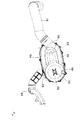
図6は後者の一例を示しており、Vベルト式無段変速機301のドライブ軸302とエンジン303のクランク軸304との間に、遠心クラッチ307が配置されているので、動力伝達系全体としては大形化するが、前述のリターンばねが不要であるので、Vベルト無段変速機301自体の構造は簡素化され、また、大きなクラッチ容量を確保することができる。なお、図6では、断面を示すためのハッチングは施していない。
FIG. 6 shows an example of the latter. Since the
図6の従来構造を簡単に説明すると、遠心クラッチ307は、エンジン303クランクケース310に取り付けられたクラッチカバー311内に収納されており、クラッチ入力軸312はクランク軸304と一体に形成され、クラッチ出力側のクラッチハウジング314は、前記クラッチカバー311の内面にボールベアリング315を介して回転自在に支持されている。
6 will be briefly described. The
変速機ケース組立体320は、クランクケース310と一体成形された変速機ケース本体321と、該変速機ケース本体321にボルトにより取り付けられた変速機カバー322とから構成されており、この変速機カバー322は、軽量化のために樹脂で製作されている。Vベルト式無段変速機301のドリブン軸330は、ギヤ式変速機331の入力軸332と一体に成形され、クランクケース310に片持ち支持されている。ドライブ軸302の一端部は、前記遠心クラッチ307の出力側のクラッチハウジング314に一体的に連結され、ドライブ軸302の他端部は、前記変速機カバー322とは別部材で形成されたアルミニウム製のボス部333に、軸受334等を介して回転自在に支持されている。前記アルミニウム製のボス部333には、変速機カバー322の内面に沿って延びるステー部333aが一体に形成され、該ステー部333aが変速機ケース本体321のカバー取付面に、変速機カバー322と共に固定されている。アルミニウム製のボス部333及びステー部333aでドライブ軸302の他端部を支持することにより、ドライブ軸302の曲げ応力に対する剛性を上げているのである。
しかし、図6に示す上記従来構造のように、ドライブ軸302の他端部を支持するために、変速機カバー322とは別部材のアルミニウム製のボス部333を備えていると、部品点数が増加すると共に、変速機ケース組立体320の組立作業も複雑化する。
However, as in the conventional structure shown in FIG. 6, in order to support the other end portion of the
本発明は、上記課題に鑑みて為されたものであり、遠心クラッチを介してクランク軸に取り付けられるVベルト式無段変速機において、部品点数を増加させることなく、高い支持剛性で、ドライブ軸を両持支持できるようにすることを目的としている。 The present invention has been made in view of the above problems, and in a V-belt type continuously variable transmission that is attached to a crankshaft via a centrifugal clutch, a drive shaft with high support rigidity without increasing the number of parts. It aims to be able to support both ends.
上記課題を解決するため、本発明に係るVベルト式無段変速機は、エンジンのクランク軸に、遠心クラッチを介して取り付けられるVベルト式無段変速機であって、ドライブ軸に設けられたドライブプーリ組立体と、ドリブン軸に設けられたドリブンプーリ組立体と、前記両プーリ組立体間に巻き掛けられたVベルトと、前記両プーリ組立体及びVベルトを収納する変速機ケース組立体と、を備えており、前記ドライブ軸は、軸方向の一端部が前記遠心クラッチの出力側回転部材に連結され、前記ドライブ軸の他端部は、前記変速機ケース組立体に形成されたボス部に回転自在に支持されている。 In order to solve the above problems, a V-belt continuously variable transmission according to the present invention is a V-belt continuously variable transmission that is attached to a crankshaft of an engine via a centrifugal clutch, and is provided on a drive shaft. A drive pulley assembly; a driven pulley assembly provided on a driven shaft; a V-belt wound between the pulley assemblies; and a transmission case assembly for housing both the pulley assembly and the V-belt. The drive shaft is connected at one end in the axial direction to the output side rotating member of the centrifugal clutch, and the other end of the drive shaft is a boss formed on the transmission case assembly. Is supported rotatably.
上記構成によると、Vベルト式無段変速機のドライブ軸の支持のために、変速機ケース組立体とは別の軸支持部材を設けることなく、前記ドライブ軸を、両持ち支持することができ、変速機ケース組立体の組立作業が容易になると共に、Vベルト式無段変速機の部品点数も減らすことができる。 According to the above configuration, for supporting the drive shaft of the V-belt type continuously variable transmission, the drive shaft can be supported at both ends without providing a shaft support member separate from the transmission case assembly. As a result, the assembly work of the transmission case assembly is facilitated, and the number of parts of the V-belt type continuously variable transmission can be reduced.
本発明は、上記特徴に加え、次のような特徴を具備することができる。
(1)前記変速機ケース組立体は、前記エンジンのクランクケースに固着又は一体に形成された変速機ケース本体と、該変速機ケース本体に取り付けられたアルミニウム製又はアルミニウム合金製の変速機カバーとから構成され、前記ボス部は、前記変速機カバーに形成されている。
In addition to the above features, the present invention can have the following features.
(1) The transmission case assembly includes a transmission case main body fixedly or integrally formed with the crankcase of the engine, and an aluminum or aluminum alloy transmission cover attached to the transmission case main body. The boss portion is formed on the transmission cover.
上記構成によると、アルミニウム製又はアルミニウム合金製の変速機カバーに形成したボス部でドライブ軸の他端部を支持するので、ドライブ軸の支持剛性を向上させることができると共に、変速機カバーの強度も向上する。また、放熱性も向上する。 According to the above configuration, since the other end of the drive shaft is supported by the boss formed on the transmission cover made of aluminum or aluminum alloy, the support rigidity of the drive shaft can be improved and the strength of the transmission cover can be improved. Will also improve. Moreover, heat dissipation is also improved.
(2)前記ドライブ軸の前記一端部は、前記変速機ケース本体に形成された軸支持部分に、前記遠心クラッチの前記出力側回転部材と共に支持されている。 (2) The one end portion of the drive shaft is supported together with the output side rotation member of the centrifugal clutch on a shaft support portion formed in the transmission case main body.
上記構成によると、ドライブ軸の一端部の支持構造も簡素化することができる。 According to the said structure, the support structure of the one end part of a drive shaft can also be simplified.
(3)前記変速機カバーには、補強用のリブが形成されている。この補強用のリブとして、前記ボス部の中心より放射状に延びるように形成することができる。 (3) Reinforcing ribs are formed on the transmission cover. The reinforcing rib can be formed to extend radially from the center of the boss portion.
上記構成によると、変速機カバーの肉厚を大きくすることなく、変速機カバーの剛性を上げ、ドライブ軸の他端部の支持強度を高めることができる。特に、ボス部から放射状にリブを形成すると、ボス部及びその近傍の剛性を集中的に向上させることができる。また、補強用のリブが変速機カバーの振動を低減し、騒音の発生を少なくできる。 According to the above configuration, it is possible to increase the rigidity of the transmission cover and increase the support strength of the other end portion of the drive shaft without increasing the thickness of the transmission cover. In particular, when the ribs are formed radially from the boss portion, the rigidity of the boss portion and its vicinity can be intensively improved. Further, the reinforcing ribs can reduce the vibration of the transmission cover and reduce the generation of noise.
(4)前記変速機カバーと前記変速機ケース本体との合わせ面には、シールが配置されている。 (4) A seal is disposed on a mating surface between the transmission cover and the transmission case main body.
上記構成によると、防塵効果を有することは勿論のこと、エンジン等の振動が変速機カバーに伝わるのを防ぎ、騒音の発生を防ぐことができる。 According to the above configuration, it is possible to prevent the generation of noise by preventing vibrations of the engine or the like from being transmitted to the transmission cover as well as having a dustproof effect.
[本発明の第1の実施の形態]
図1〜図4は本発明の第1の実施の形態によるVベルト式無段変速機を備えたエンジン及び四輪走行車を示しており、これらの図面に基づいて本発明の一実施の形態を説明する。
[First embodiment of the present invention]
1 to 4 show an engine and a four-wheel vehicle equipped with a V-belt type continuously variable transmission according to a first embodiment of the present invention, and one embodiment of the present invention is based on these drawings. Will be explained.
図1は前記四輪走行車の左側面図であり、小形の不整地用四輪走行車(いわゆる、ユーティリティビークル)は、車体フレーム1の前部に左右一対の前車輪2を備え、車体フレーム1の後部に左右一対の後車輪3を備え、前車輪2と後車輪3との間に、キャビンフレーム5で囲まれたキャビン6を備え、キャビン6の後方に荷台7を備え、前車輪2の上方と後車輪3の上方にそれぞれフェンダー(図示せず)を備え、キャビン6の前方に、ボンネット8及びバンパー9等を備えている。
FIG. 1 is a left side view of the four-wheel vehicle. A small four-wheel vehicle for rough terrain (a so-called utility vehicle) has a pair of left and right front wheels 2 at the front of a body frame 1. 1 includes a pair of left and right rear wheels 3 at a rear portion, a
キャビン6内の前半部にはベンチ形の前シート10が設置され、キャビン6内の後半部には折り畳み式のベンチ形の後シート11が設置され、キャビン6の前端部にはダッシュボード(操作部)12が設けられている。
A bench-
エンジンルーム14は、前シート10の下側空間から後シート11の下側空間に亘るように形成されると共に、車輌の車幅方向の中央部に位置しており、このエンジンルーム14内にエンジン20が収納され、車体フレーム1に支持されている。エンジン20は単気筒エンジンであり、前傾した単一のシリンダ21を有している。特に、エンジン20の全高を低くするために、前記シリンダ21の傾斜角度を、たとえば鉛直方向に対して略60°又はそれ以上の傾斜角度に設定している。エンジン20としては、V型又はその他の形式の気筒を有するエンジンを備えることもできる。
The
エンジン20の排気ポート(図示せず)に接続された排気管25は、後方に延び、荷台7の下側に配置された排気マフラー26に接続している。
An
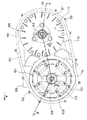
図4において、エンジン20のクランクケース30の左側壁には、クラッチカバー40aを一体に有する変速機ケース本体40が複数のボルト44により結合されており、前記クラッチカバー40aとクランクケース30の左側壁とにより、遠心クラッチ39を収納するためのクラッチ室41を形成している。前記変速機ケース本体40は、アルミニウム又はアルミニウム合金で製作されている。
In FIG. 4, a
前記変速機ケース本体40の左端のカバー取付面には、変速機カバー42が、弾性材製のトリムシール51を介して複数のボルト45により結合されており、無段変速機ケース本体40と無段変速機カバー42とにより、変速機ケース組立体38を構成している。該変速機ケース組立体38内が無段変速機室43となっている。前記変速機カバー42は、前記変速機ケース本体40と同様に、アルミニウム又はアルミニウム合金で製作されている。また、変速機ケース本体40と変速機カバー42とは、ノックピン52により、相互に位置決めされている。上述のように、変速機ケース本体40及び変速機カバー42が、アルミニウム又はアルミニウム合金で製作されている場合、高い強度を得ることができると共に放熱性に優れた構造となる。
A
エンジン20のクランク軸35の左ジャーナル部35bは、クランクケース30の左側壁の軸受孔に、ボールベアリング36を介して回転自在に支持されている。前記左ジャーナル部35bには、前記クラッチ室41内に突出するクラッチ入力側のクラッチ軸55が一体に形成されている。該クラッチ軸55の外周面には、遠心クラッチ39のインナー部材56のボス部56aがクラッチ軸55と一体回転するようにスプライン嵌合している。前記ボス部56aの外周面には、ワンウエイクラッチを介してクラッチハウジング60のボス部60aが嵌合している。該クラッチハウジング60のボス部60aはVベルト式無段変速機46のドライブ軸59と一体に形成されると共に、ボールベアリング61を介してクラッチカバー40aの内周面に回転自在に支持されている。
The
クランクケース30の後部にはトランスミッション室31が備えられており、該トランスミッション室31内には、変速入力軸32及び変速出力軸33等を有するギヤ式トランスミッション(ギヤ等は省略)が配置されている。変速出力軸33は、ベベルギヤ機構及び動力伝達軸等を介して後車輪3(図1)に動力伝達可能に連結されている。変速入力軸32は、トランスミッション室31の左側壁に回転自在に支持されており、この変速入力軸32と一体に、Vベルト式無段変速機46のドリブン軸63が形成されている。
A
(Vベルト式無段変速機46)
無段変速機室43内に配置されるVベルト式無段変速機46は、無段変速機室43の前部に配置されたドライブプーリ組立体65と、無段変速機室43の後部に配置されたドリブンプーリ組立体66と、両プーリ組立体65,66に亘って巻きか掛けられたVベルト67と、両プーリ組立体65,66及びVベルト67を収納する前記変速機ケース組立体38と、から構成されている。
(V belt type continuously variable transmission 46)
A V-belt type continuously
(ドライブプーリ組立体65の構造)
ドライブプーリ組立体65は、前記ドライブ軸59にドライブ軸方向に移動不能に固着された固定シーブ69と、ドライブ軸59にドライブ軸方向に移動可能に嵌合した可動シーブ70と、フライウエイト式のシーブ推力発生機構71等から構成されている。ドライブ軸59に軸方向の一端部、すなわち右端部は、前述のように、遠心クラッチ39のクラッチ出力側のハウジング60のボス部60aと一体に形成され、前記ボールベアリング61を介してクラッチカバー40aの内周面に支持されている。ドライブ軸59の他端部、すなわち左端部は、変速機カバー42に形成されたボス部93の内周面に、ボールベアリング94を介して回転自在に支持されている。すなわち、ドライブ軸59は、クラッチカバー40aの内周面と変速機カバー42のボス部93とにより、両持ち支持されている。前記変速機カバー42のボス部93の中心は、前記ノックピン52により、変速機ケース40の軸受孔部分(ボールベアリング61を支持する部分)の中心と一致させられている。
(Structure of drive pulley assembly 65)
The drive
固定シーブ69はドライブ軸59の右端部に螺着されている。可動シーブ70は固定シーブ69に対してドライブ軸方向の左方から対向すると共にドライブ軸59に対してドライブ軸方向移動可能に嵌合している。両シーブ69、70に形成された円錐状の挟圧面により、Vベルト67を左右から挟圧し、保持している。
The fixed
可動シーブ70の背面には左方に延びる複数の連結腕72を介して四角枠状の受け板73が結合され、該受け板73は可動シーブ70と一体にドライブ軸方向に移動する。
A square frame-shaped receiving
シーブ推力発生機構71は、可動シーブ70の背面と前記受け板73との間に配設され、複数(たとえば4個)のフライウエイト75と、ローラ支持部材76と、複数の受圧ローラ77と、から構成されている。ローラ支持部材76はドライブ軸59の左端部に螺着され、ドライブ軸59と一体に回転するようになっており、ローラ支持部材76が前記連結腕72に周方向に係合することにより、可動シーブ70がローラ支持部材76を介してドライブ軸59と一体的に回転する。複数のフライウエイト75は、ドライブ軸59の周方向に間隔をおいて配置されている。各フライウエイト75は、可動シーブ69の背面に、支軸78を介して回動自在に支持され、前記各受圧ローラ77に右方から当接している。
The sheave
(ドリブンプーリ組立体66の構造)
ドリブンプーリ組立体66は、前記ドリブン軸63に対してドリブン軸方向に移動不能に固定される固定シーブ81と、ドリブン軸63にドリブン軸方向に移動可能に嵌合する可動シーブ82等と、から構成されている。ドリブン軸63は、前述のように、ギヤ式変速機の変速入力軸32と一体に形成されており、クランクケース30の左側壁のボス部95に、ボールベアリング96を介して片持ち支持されている。
(Structure of the driven pulley assembly 66)
The driven
ドリブン軸63の外周面には、複数のスパイラル状カム溝83aを有するカム筒83が固着されており、該カム筒83の左端部に、固定シーブ81の内周端が螺着されている。すなわち、固定シーブ81及びカム筒83は、ドリブン軸63と一体に回転するようになっている。可動シーブ82は、固定シーブ81に対してドリブン軸方向の右方から対向配置され、可動シーブ82の内周端部にはローラ支持用のスリーブ85が一体に結合されている。該スリーブ85は、カム筒83の外周面にドリブン軸方向移動可能に嵌合すると共に、調圧ばね87により固定シーブ81側(左側)に付勢されており、上記調圧ばね87により、ドリブンプレート組立体66のベルト巻掛半径を最大径(ロー位置)に維持するようになっている。
A
スリーブ85には前記スパイラル状カム溝83aに移動可能に係合するローラ86が支持されており、車輌走行中、車輪側の負荷の増大に伴ってVベルト67の張力が増大すると、可動シーブ82が固定シーブ81に対して相対的に回転方向側に回転し、かつ、カム筒83のカム溝83aとローラ86とのカム作用により、カム筒83に対して、スリーブ85及び可動シーブ82が右方へスパイラル状に移動し、ドリブンプーリ組立体66のベルトの巻掛半径を減少させる。
(Vベルト式無段変速機46の冷却装置)
The
(Cooling device for V-belt type continuously variable transmission 46)
図3において、変速機ケース本体40の上壁には、ドライブ軸59の略直上位置に、空気取入口88が開口しており、図2に示すように、前記空気取入口88には、空気取入ダクト89が接続されている。この空気取入ダクト89は側面視で概ねL字状に形成されると共に前方に延び、たとえば図1のボンネット8内に連通している。
In FIG. 3, an
図2において、変速機カバー42の後端部には、ドリブン軸63の後方近傍位置に、空気排出口90が開口しており、この空気排出口90には、空気排出ダクト91が接続されている。
In FIG. 2, an
図4において、固定シーブ69の背面(右側面)には、周方向に等間隔を置いて複数の第1の冷却フィン101が形成されている。該第1の冷却フィン101の右端縁に対して、ドライブ軸方向の右方に所定隙間を隔てた位置に、第1の冷却ファン用の第1のケーシング102が配置されている。該第1のケーシング102は、変速機ケース本体40のクラッチカバー40aの部分にボルト103により固着されており、第1のケーシング102の中央部には、クラッチカバー40aを囲むように空気入口105を備えている。
In FIG. 4, a plurality of
図3及び図4において、ドリブンプーリ組立体66にも、周方向に等間隔を置いて複数の第2の冷却フィン111が形成されている。固定シーブ81の前半部分には、第2の冷却フィン111の左端縁に対して、ドライブ軸方向の左方に所定隙間を隔てた位置に、略半円弧状の第2のケーシング112が配置されている。
3 and 4, the driven
図4において、ドリブンプーリ組立体66の固定シーブ81の後半部分には、無段変速機カバー42の一部42aが、第2の冷却フィン111の左端縁に対して所定間隔で左方から対向しており、これにより、前記無段変速機カバー42の一部42aが、第2のケーシングの役目を果たしている。
In FIG. 4, a portion 42 a of the continuously
変速機ケース本体40の両プーリ組立体65,66の前後方向間に対応する位置には、左方に突出する空気ガイド部120が一体に形成されており、この空気ガイド部120は、ドライブプーリ組立体65の第1の冷却ファン(固定シーブ69)から送り出される空気を、後左方のドリブンプーリ組立体66の中央部の空気入口115に導いている。
An
(作用)
図4において、エンジン停止時又はアイドル回転時は、遠心クラッチ39が切れているので、Vベルト式無段変速機46のドライブ軸59は回転していない。このとき、ドライブプーリ組立体65の可動シーブ70は、受け板73と一体的に最大開位置まで移動している。一方、ドリブンプーリ組立体66の可動シーブ82は、調圧ばね87により、最も固定シーブ81側(最左端位置側)に移動している。すなわち、Vベルト式無段変速機46の減速比は、ロー状態(最大減速状態)となっている。
(Function)
In FIG. 4, when the engine is stopped or idling, the centrifugal clutch 39 is disengaged, so that the
アイドリング回転からエンジン回転数を増加させると、遠心クラッチ39が接続され、ドライブ軸59が回転し始め、まず、ロー状態で、ドライブプーリ組立体65からVベルト67を介してドリブンプーリ組立体66に動力が伝達される。
When the engine speed is increased from idling rotation, the centrifugal clutch 39 is connected and the
エンジン回転数がさらに増加すると、シーブ推力発生機構71のフライウエイト75が遠心力により矢印S方向に回動し、受圧ローラ77を押す。受圧ローラ77自体はドライブ軸方向に移動しないので、この受圧ローラ77の反力より、可動シーブ70と受け板73とは、一体的にドライブ軸方向の右方に移動し、可動シーブ70と固定シーブ69との間隔を縮める。これにより、Vベルト67が径方向の外方へと移動し、巻掛半径が増加する。
When the engine speed further increases, the
ドライブプーリ組立体65のVベルト67の巻掛半径が増加すると、ドリブンプーリ組立体66では、Vベルト67の張力が増加することにより、Vベルト67の左右側面と両シーブ81,82との圧接力が増加する。これにより、可動シーブ82は、調圧ばね87に抗して、固定シーブ81に対してスパイラル状に右方に移動させられ、可動シーブ82と固定シーブ81との間隔を広げ、巻掛半径が減少する。
When the winding radius of the
上記のように、ドライブプーリ組立体65の巻掛半径の増加と、ドリブンプーリ組立体66の巻き掛け半径の減少により、減速比が小さくなる。すなわち、ロー状態からハイ状態へと移行する。
As described above, the reduction ratio is reduced by increasing the winding radius of the
該実施の形態によると、変速機カバー42に形成したボス部93により、ドライブ軸59の他端部(左端部)を支持しているので、ドライブ軸59を支持するために、変速機カバー42とは別の軸支持部材を設ける必要はなく、Vベルト式無段変速機46の部品点数を減らし、構造を簡素化できると共に、組立作業も容易になる。しかも、変速機カバー42を、変速ケース本体40と同様にアルミニウム又はアルミニウム合金製としているので、ドライブ軸59の支持剛性がさらに向上し、かつ、優れた放熱性を得ることができる。
According to this embodiment, since the other end portion (left end portion) of the
また、ドライブ軸59の一端部は、遠心クラッチ39のクラッチ出力側のハウジング60と共に、クラッチカバー40aに支持しているので、これによっても、部品点数を減らすことができる。
In addition, since one end portion of the
また、前記変速機ケース本体40と変速機カバー42との合わせ面には、弾性材製のトリムシール51を配置しているので、エンジン等の振動が変速機カバー42に伝わるのを防ぎ、騒音の発生を防ぐことができる。
Further, since the
[その他の実施の形態]
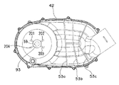
(1)図5は、第2の実施の形態であり、変速機カバー42の左側面図である。この変速機カバー42は、第1の実施の形態と同様に、アルミニウム製又はアルミニウム合金製であり、ドライブ軸支持用のボス部93を一体に備えており、更に、剛性を高くするために、左側面(外側面)に複数の、たとえば3本の補強リブ53a、53b、53cが形成されている。
[Other embodiments]
(1) FIG. 5 is a left side view of the
これらの補強リブ53a、53b、53cは、変速機カバー42の後半部に、前後方向に間隔を置いて配置されており、各補強リブ53a、53b、53cは略上下方向に延びており、変速機カバー42の上端から下端に至っている。前側の補強リブ53aは、側方から見て、略直線状に形成されており、中間の補強リブ53bは、側方から見て、少し折れ曲がっており、後側の補強リブ53cは、側方から見て、L字状に折れ曲がっている。
These reinforcing
このように変速機カバー42に補強リブ53a、53b、53cを形成することにより、変速機カバー42の肉厚を大きくすることなく、剛性を上げることができ、また、エンジン振動又はVベルト式無段変速機の振動に対しても、その振動を抑制することができる。
By forming the reinforcing
さらに、図5に示す実施の形態では、変速機カバー42の前部の左側面(外側面)及び右側面(内側面)に、ボス部93の中心点から放射状に延びる複数の補強リブ201,202,203,204が形成されている。このようにボス部93の周囲に放射状の補強用のリブ201,202,203,204を形成していることにより、変速機カバー42の強度が向上するのは勿論のこと、ドライブ軸59の他端部を支持する前記ボス部93の支持剛性を、集中的に向上させることができる。
Further, in the embodiment shown in FIG. 5, a plurality of reinforcing
(2)前記実施の形態では、変速機ケース本体40を、クランクケース30とは別体に形成し、ボルト44によりクランクケース30に固定しているが、変速機ケース本体40をクランクケース30と一体に成形することもできる。この場合は、クランクケース30は、左右分割構造であることが好ましい。
(2) In the above embodiment, the transmission case
(3)本発明は、図1のような不整地用四輪走行車に搭載されるエンジンに限定されるものではなく、自動二輪車及び三輪車等の各種車輌、又は小形ウォータクラフト等に搭載される乗物用のエンジンに適用できるのは勿論のこと、乗物用のエンジン以外にも適用できる。さらに、複数気筒のエンジンにも適用することもできる。 (3) The present invention is not limited to the engine mounted on the four-wheel vehicle for rough terrain as shown in FIG. 1, but mounted on various vehicles such as motorcycles and tricycles, or small watercrafts. Needless to say, the present invention can be applied not only to a vehicle engine but also to a vehicle engine. Further, it can be applied to a multi-cylinder engine.
(4)本発明は、前記実施の形態の構造に限定されるものではなく、特許請求の範囲に記載した内容を逸脱しない範囲で考えられる各種の変形例が含まれる。 (4) The present invention is not limited to the structure of the embodiment described above, and includes various modifications that can be considered without departing from the scope of the claims.
20 エンジン
30 クランクケース
35 クランク軸
38 変速機ケース組立体
39 遠心クラッチ
40 変速機ケース本体
42 変速機カバー
51 トリムシール
53a,53b,53c 補強リブ
59 ドライブ軸
60 出力側のハウジング(出力側回転部材の一例)
61 ボールベアリング(軸支持部分)
63 ドリブン軸
65 ドライブプーリ組立体
66 ドリブンプーリ組立体
67 Vベルト
93 ボス部
201,202,203,204 放射状配置の補強用のリブ
20
61 Ball bearing (shaft support part)
63 Driven
Claims (6)
ドライブ軸に設けられたドライブプーリ組立体と、
ドリブン軸に設けられたドリブンプーリ組立体と、
前記両プーリ組立体間に巻き掛けられたVベルトと、
前記両プーリ組立体及びVベルトを収納する変速機ケース組立体と、を備えており、
前記ドライブ軸は、軸方向の一端部が前記遠心クラッチの出力側回転部材に連結され、前記ドライブ軸の他端部は、前記変速機ケース組立体に形成されたボス部に回転自在に支持されている、Vベルト式無段変速機。 A V-belt continuously variable transmission attached to the crankshaft of an engine via a centrifugal clutch,
A drive pulley assembly provided on the drive shaft;
A driven pulley assembly provided on the driven shaft;
A V-belt wound between the pulley assemblies;
A transmission case assembly that houses both the pulley assemblies and the V-belt,
One end of the drive shaft in the axial direction is connected to the output side rotation member of the centrifugal clutch, and the other end of the drive shaft is rotatably supported by a boss formed in the transmission case assembly. V-belt type continuously variable transmission.
前記変速機ケース組立体は、前記エンジンのクランクケースに固着又は一体に形成された変速機ケース本体と、該変速機ケース本体に取り付けられたアルミニウム製又はアルミニウム合金製の変速機カバーとから構成され、
前記ボス部は、前記変速機カバーに形成されている、Vベルト式無段変速機。 In the V belt type continuously variable transmission according to claim 1,
The transmission case assembly includes a transmission case main body fixed to or integrally formed with the crankcase of the engine, and an aluminum or aluminum alloy transmission cover attached to the transmission case main body. ,
The boss is a V-belt type continuously variable transmission formed on the transmission cover.
前記ドライブ軸の前記一端部は、前記変速機ケース本体に形成された軸支持部分に、前記遠心クラッチの前記出力側回転部材と共に支持されている、Vベルト式無段変速機。 In the V belt type continuously variable transmission according to claim 2,
The V belt type continuously variable transmission, wherein the one end portion of the drive shaft is supported by a shaft support portion formed in the transmission case main body together with the output side rotation member of the centrifugal clutch.
前記変速機カバーには、補強用のリブが形成されている、Vベルト式無段変速機。 In the V belt type continuously variable transmission according to claim 2 or 3,
A V-belt type continuously variable transmission in which a reinforcing rib is formed on the transmission cover.
前記補強用のリブが、前記ボス部の中心より放射状に延びるように形成されている、Vベルト式無段変速機。 In the V belt type continuously variable transmission according to claim 4,
A V-belt type continuously variable transmission in which the reinforcing ribs are formed so as to extend radially from the center of the boss portion.
前記変速機カバーと前記変速機ケース本体との合わせ面には、シールが配置されている、Vベルト式無段変速機。 In the V belt type continuously variable transmission according to any one of claims 2 to 5,
A V-belt type continuously variable transmission in which a seal is disposed on a mating surface between the transmission cover and the transmission case main body.
Priority Applications (2)
| Application Number | Priority Date | Filing Date | Title |
|---|---|---|---|
| JP2008330145A JP2010151237A (en) | 2008-12-25 | 2008-12-25 | V-belt type continuously variable transmission |
| US12/639,296 US8382620B2 (en) | 2008-12-25 | 2009-12-16 | V-belt type continuously variable transmission |
Applications Claiming Priority (1)
| Application Number | Priority Date | Filing Date | Title |
|---|---|---|---|
| JP2008330145A JP2010151237A (en) | 2008-12-25 | 2008-12-25 | V-belt type continuously variable transmission |
Publications (1)
| Publication Number | Publication Date |
|---|---|
| JP2010151237A true JP2010151237A (en) | 2010-07-08 |
Family
ID=42285647
Family Applications (1)
| Application Number | Title | Priority Date | Filing Date |
|---|---|---|---|
| JP2008330145A Pending JP2010151237A (en) | 2008-12-25 | 2008-12-25 | V-belt type continuously variable transmission |
Country Status (2)
| Country | Link |
|---|---|
| US (1) | US8382620B2 (en) |
| JP (1) | JP2010151237A (en) |
Cited By (6)
| Publication number | Priority date | Publication date | Assignee | Title |
|---|---|---|---|---|
| US8863887B2 (en) | 2013-02-28 | 2014-10-21 | Kawasaki Jukogyo Kabushiki Kaisha | Utility vehicle |
| US9341255B2 (en) | 2014-04-24 | 2016-05-17 | Kawasaki Jukogyo Kabushiki Kaisha | V-belt type continuously variable transmission |
| US9410512B2 (en) | 2013-03-15 | 2016-08-09 | Kawasaki Jukogyo Kabushiki Kaisha | Air intake apparatus for four wheeled utility vehicle |
| US9528595B2 (en) | 2014-04-24 | 2016-12-27 | Kawasaki Jukogyo Kabushiki Kaisha | V-belt type continuously variable transmission |
| CN109844370A (en) * | 2016-10-06 | 2019-06-04 | 株式会社F.C.C. | CVT |
| JP2023049569A (en) * | 2021-09-29 | 2023-04-10 | 株式会社クボタ | multipurpose vehicle |
Families Citing this family (29)
| Publication number | Priority date | Publication date | Assignee | Title |
|---|---|---|---|---|
| WO2012172863A1 (en) * | 2011-06-16 | 2012-12-20 | 本田技研工業株式会社 | Clutch for transmission |
| EP2733388B1 (en) * | 2011-07-11 | 2015-09-16 | Toyota Jidosha Kabushiki Kaisha | Power transmission device for vehicle |
| US8834307B2 (en) * | 2011-10-06 | 2014-09-16 | Kawasaki Jukogyo Kabushiki Kaisha | Belt type continuously variable transmission |
| US8911312B2 (en) * | 2011-10-06 | 2014-12-16 | Kawasaki Jukogyo Kabushiki Kaisha | Belt type continuously variable transmission |
| US8556015B2 (en) | 2011-10-07 | 2013-10-15 | Kawasaki Jukogyo Kabushiki Kaisha | Utility vehicle |
| US8596406B2 (en) | 2011-10-07 | 2013-12-03 | Kawasaki Jukogyo Kabushiki Kaisha | Utility vehicle |
| JP2013231475A (en) * | 2012-04-27 | 2013-11-14 | Yamaha Motor Co Ltd | Continuously variable transmission and saddle-ride type vehicle |
| US9511761B2 (en) * | 2012-10-19 | 2016-12-06 | Kubota Corporation | Hybrid vehicle |
| US9103428B2 (en) * | 2013-03-15 | 2015-08-11 | Kawasaki Jukogyo Kabushiki Kaisha | Structure for coupling V-belt type continuously variable transmission with engine |
| US9366331B2 (en) | 2013-07-22 | 2016-06-14 | Arctic Cat Inc. | Transmission cover with improved airflow |
| EP2853781B1 (en) * | 2013-09-30 | 2016-06-01 | Honda Motor Co., Ltd. | V-belt continuously variable transmission |
| US20150133247A1 (en) * | 2013-11-13 | 2015-05-14 | Shawn Watling | Snow mobile drive assembly |
| US10648554B2 (en) * | 2014-09-02 | 2020-05-12 | Polaris Industries Inc. | Continuously variable transmission |
| JP6512967B2 (en) | 2015-07-02 | 2019-05-15 | 株式会社クボタ | Work vehicle |
| ITUB20156895A1 (en) * | 2015-12-10 | 2017-06-10 | Piaggio & C Spa | TRANSMISSION DEVICE WITH CONTINUOUS CHANGE WITH CHANGE ADJUSTMENT DEVICE |
| US9863523B2 (en) * | 2016-03-21 | 2018-01-09 | Textron Innovations Inc. | Continuously variable transmission |
| US10197149B2 (en) * | 2016-03-23 | 2019-02-05 | Kawasaki Jukogyo Kabushiki Kaisha | V-belt type continuously variable transmission |
| US10697532B2 (en) * | 2016-12-22 | 2020-06-30 | Polaris Industries Inc. | Housing for a transmission |
| DE102017213827A1 (en) * | 2017-08-08 | 2019-02-14 | Aktiebolaget Skf | Bearing carrier or housing part and method for producing a bearing carrier or a housing part |
| WO2019142530A1 (en) * | 2018-01-20 | 2019-07-25 | ジヤトコ株式会社 | Stepless transmission |
| CN111836980A (en) * | 2018-03-19 | 2020-10-27 | 北极星工业有限公司 | CVT |
| CN111801518B (en) | 2018-03-19 | 2023-10-31 | 北极星工业有限公司 | Electronic CVT with friction clutch |
| US10054213B1 (en) * | 2018-04-09 | 2018-08-21 | Borgwarner Inc. | Vehicle drivetrain component having an internal vent relocation tube for venting a housing of the vehicle drivetrain component |
| US11543006B2 (en) | 2019-06-21 | 2023-01-03 | Team Industries, Inc. | Variable torque limiting clutch for a steel belt continuously variable transmission |
| US11499608B2 (en) * | 2019-06-21 | 2022-11-15 | Team Industries, Inc. | Integrated launch clutch and drive sheave for steel belt continuously variable transmission |
| US12504070B2 (en) | 2021-01-29 | 2025-12-23 | Polaris Industries Inc. | Electronically-controlled continuously variable transmission for a utility vehicle |
| US11913537B2 (en) * | 2022-01-18 | 2024-02-27 | Kris Werth, Inc. | CVT belt cooling system |
| US11821376B1 (en) | 2022-05-20 | 2023-11-21 | Kawasaki Motors, Ltd. | Utility vehicle |
| US12467533B2 (en) | 2023-10-18 | 2025-11-11 | Team Industries, Inc. | High-low shifting active torque management continuously variable transmission system |
Citations (7)
| Publication number | Priority date | Publication date | Assignee | Title |
|---|---|---|---|---|
| JPS6362951A (en) * | 1986-09-02 | 1988-03-19 | Honda Motor Co Ltd | Vehicles using belt-type transmissions |
| JPH08128517A (en) * | 1994-10-31 | 1996-05-21 | Jatco Corp | Transmission case |
| JPH1130314A (en) * | 1997-07-08 | 1999-02-02 | Jatco Corp | Case structure for automatic transmission |
| JP2003042270A (en) * | 2001-07-25 | 2003-02-13 | Yamaha Motor Co Ltd | Cooling structure of belt transmission |
| JP2003172437A (en) * | 2001-12-07 | 2003-06-20 | Suzuki Motor Corp | Cooling structure of belt type continuously variable transmission |
| JP2004232805A (en) * | 2003-01-31 | 2004-08-19 | Yamaha Motor Co Ltd | V-belt type continuously variable transmission cooling structure |
| JP2007198457A (en) * | 2006-01-25 | 2007-08-09 | Yamaha Motor Co Ltd | Seal member for belt type continuously variable transmission and belt type continuously variable transmission |
Family Cites Families (5)
| Publication number | Priority date | Publication date | Assignee | Title |
|---|---|---|---|---|
| JP3524533B2 (en) | 2001-12-19 | 2004-05-10 | 川崎重工業株式会社 | In-vehicle V-belt continuously variable transmission |
| JP2004156657A (en) * | 2002-11-05 | 2004-06-03 | Yamaha Motor Co Ltd | Engine drive belt cooling structure |
| JP2007071254A (en) * | 2005-09-05 | 2007-03-22 | Yamaha Motor Co Ltd | V-belt type continuously variable transmission and saddle riding type vehicle |
| JP2007071255A (en) | 2005-09-05 | 2007-03-22 | Yamaha Motor Co Ltd | V-belt type continuously variable transmission and saddle riding type vehicle |
| JP4833675B2 (en) | 2006-01-27 | 2011-12-07 | 本田技研工業株式会社 | Hydraulic control device for automatic transmission |
-
2008
- 2008-12-25 JP JP2008330145A patent/JP2010151237A/en active Pending
-
2009
- 2009-12-16 US US12/639,296 patent/US8382620B2/en not_active Expired - Fee Related
Patent Citations (7)
| Publication number | Priority date | Publication date | Assignee | Title |
|---|---|---|---|---|
| JPS6362951A (en) * | 1986-09-02 | 1988-03-19 | Honda Motor Co Ltd | Vehicles using belt-type transmissions |
| JPH08128517A (en) * | 1994-10-31 | 1996-05-21 | Jatco Corp | Transmission case |
| JPH1130314A (en) * | 1997-07-08 | 1999-02-02 | Jatco Corp | Case structure for automatic transmission |
| JP2003042270A (en) * | 2001-07-25 | 2003-02-13 | Yamaha Motor Co Ltd | Cooling structure of belt transmission |
| JP2003172437A (en) * | 2001-12-07 | 2003-06-20 | Suzuki Motor Corp | Cooling structure of belt type continuously variable transmission |
| JP2004232805A (en) * | 2003-01-31 | 2004-08-19 | Yamaha Motor Co Ltd | V-belt type continuously variable transmission cooling structure |
| JP2007198457A (en) * | 2006-01-25 | 2007-08-09 | Yamaha Motor Co Ltd | Seal member for belt type continuously variable transmission and belt type continuously variable transmission |
Cited By (7)
| Publication number | Priority date | Publication date | Assignee | Title |
|---|---|---|---|---|
| US8863887B2 (en) | 2013-02-28 | 2014-10-21 | Kawasaki Jukogyo Kabushiki Kaisha | Utility vehicle |
| US9410512B2 (en) | 2013-03-15 | 2016-08-09 | Kawasaki Jukogyo Kabushiki Kaisha | Air intake apparatus for four wheeled utility vehicle |
| US9341255B2 (en) | 2014-04-24 | 2016-05-17 | Kawasaki Jukogyo Kabushiki Kaisha | V-belt type continuously variable transmission |
| US9528595B2 (en) | 2014-04-24 | 2016-12-27 | Kawasaki Jukogyo Kabushiki Kaisha | V-belt type continuously variable transmission |
| CN109844370A (en) * | 2016-10-06 | 2019-06-04 | 株式会社F.C.C. | CVT |
| JP2023049569A (en) * | 2021-09-29 | 2023-04-10 | 株式会社クボタ | multipurpose vehicle |
| JP7645756B2 (en) | 2021-09-29 | 2025-03-14 | 株式会社クボタ | Multi-purpose vehicles |
Also Published As
| Publication number | Publication date |
|---|---|
| US20100167853A1 (en) | 2010-07-01 |
| US8382620B2 (en) | 2013-02-26 |
Similar Documents
| Publication | Publication Date | Title |
|---|---|---|
| JP2010151237A (en) | V-belt type continuously variable transmission | |
| US8911312B2 (en) | Belt type continuously variable transmission | |
| US10138823B2 (en) | Combustion engine air intake system for motorcycle | |
| CN1361354A (en) | Radiating apparatus for vehicle | |
| JP6110954B2 (en) | Supercharger power transmission device | |
| US6405823B1 (en) | Vehicle power unit | |
| CN101186228B (en) | Motorcycle | |
| WO2006003904A1 (en) | V-belt type continuously variable transmission for small-sized vehicle and saddle-riding type vehicle | |
| US7647995B2 (en) | Riding type vehicle | |
| EP1967768B1 (en) | Continuously variable transmission | |
| JP4660286B2 (en) | Power unit | |
| JPH08175477A (en) | Power switching device for engine and motor of motorcycles, etc. | |
| JP2007062716A (en) | Saddle riding vehicle | |
| KR101157363B1 (en) | Crank case structure of internal combustion engine | |
| JP5654389B2 (en) | Continuous transmission structure | |
| EP1666721B1 (en) | Internal combustion engine | |
| JP4627067B2 (en) | Motorcycle | |
| US7434645B2 (en) | Swing arm structure in motorcycle | |
| JP2006168468A (en) | Motorcycle power unit and motorcycle | |
| JP3150481U (en) | Saddle riding vehicle | |
| JP2004052908A (en) | Power unit for vehicle | |
| JP7401585B2 (en) | vehicle transmission | |
| JP2005096690A (en) | Arrangement structure of turbocharger | |
| JP2024095190A (en) | V-belt type continuously variable transmission | |
| JPH05139366A (en) | Electric scooters |
Legal Events
| Date | Code | Title | Description |
|---|---|---|---|
| A621 | Written request for application examination |
Free format text: JAPANESE INTERMEDIATE CODE: A621 Effective date: 20110802 |
|
| A977 | Report on retrieval |
Free format text: JAPANESE INTERMEDIATE CODE: A971007 Effective date: 20120515 |
|
| A131 | Notification of reasons for refusal |
Free format text: JAPANESE INTERMEDIATE CODE: A131 Effective date: 20120522 |
|
| A02 | Decision of refusal |
Free format text: JAPANESE INTERMEDIATE CODE: A02 Effective date: 20120925 |