EP1760355A1 - Amortisseur de vibrations de torsion avec des ressorts à fil dans une poulie d'entraînement - Google Patents
Amortisseur de vibrations de torsion avec des ressorts à fil dans une poulie d'entraînement Download PDFInfo
- Publication number
- EP1760355A1 EP1760355A1 EP06017389A EP06017389A EP1760355A1 EP 1760355 A1 EP1760355 A1 EP 1760355A1 EP 06017389 A EP06017389 A EP 06017389A EP 06017389 A EP06017389 A EP 06017389A EP 1760355 A1 EP1760355 A1 EP 1760355A1
- Authority
- EP
- European Patent Office
- Prior art keywords
- hub
- wire springs
- rim
- cup
- drive
- Prior art date
- Legal status (The legal status is an assumption and is not a legal conclusion. Google has not performed a legal analysis and makes no representation as to the accuracy of the status listed.)
- Granted
Links
- 229920001971 elastomer Polymers 0.000 claims description 8
- 239000006096 absorbing agent Substances 0.000 claims description 5
- 230000003534 oscillatory effect Effects 0.000 claims 1
- 238000002485 combustion reaction Methods 0.000 abstract description 5
- 230000010355 oscillation Effects 0.000 abstract description 2
- 238000013016 damping Methods 0.000 description 27
- 239000002184 metal Substances 0.000 description 8
- 230000008878 coupling Effects 0.000 description 5
- 238000010168 coupling process Methods 0.000 description 5
- 238000005859 coupling reaction Methods 0.000 description 5
- 239000000806 elastomer Substances 0.000 description 5
- 239000000463 material Substances 0.000 description 5
- 230000002349 favourable effect Effects 0.000 description 4
- 230000000694 effects Effects 0.000 description 3
- 230000002093 peripheral effect Effects 0.000 description 3
- 230000006835 compression Effects 0.000 description 2
- 238000007906 compression Methods 0.000 description 2
- 238000005553 drilling Methods 0.000 description 2
- 230000007613 environmental effect Effects 0.000 description 2
- 230000008029 eradication Effects 0.000 description 2
- 238000003780 insertion Methods 0.000 description 2
- 239000000725 suspension Substances 0.000 description 2
- 230000005540 biological transmission Effects 0.000 description 1
- 238000010276 construction Methods 0.000 description 1
- 238000011109 contamination Methods 0.000 description 1
- 230000001419 dependent effect Effects 0.000 description 1
- 239000007789 gas Substances 0.000 description 1
- 230000017525 heat dissipation Effects 0.000 description 1
- 230000037431 insertion Effects 0.000 description 1
- 239000007788 liquid Substances 0.000 description 1
- 239000007769 metal material Substances 0.000 description 1
- 238000000034 method Methods 0.000 description 1
- 239000003921 oil Substances 0.000 description 1
- 230000000737 periodic effect Effects 0.000 description 1
- 239000004033 plastic Substances 0.000 description 1
- 230000002787 reinforcement Effects 0.000 description 1
- 125000006850 spacer group Chemical group 0.000 description 1
- 239000004636 vulcanized rubber Substances 0.000 description 1
Images


Classifications
-
- F—MECHANICAL ENGINEERING; LIGHTING; HEATING; WEAPONS; BLASTING
- F16—ENGINEERING ELEMENTS AND UNITS; GENERAL MEASURES FOR PRODUCING AND MAINTAINING EFFECTIVE FUNCTIONING OF MACHINES OR INSTALLATIONS; THERMAL INSULATION IN GENERAL
- F16D—COUPLINGS FOR TRANSMITTING ROTATION; CLUTCHES; BRAKES
- F16D3/00—Yielding couplings, i.e. with means permitting movement between the connected parts during the drive
- F16D3/50—Yielding couplings, i.e. with means permitting movement between the connected parts during the drive with the coupling parts connected by one or more intermediate members
- F16D3/52—Yielding couplings, i.e. with means permitting movement between the connected parts during the drive with the coupling parts connected by one or more intermediate members comprising a continuous strip, spring, or the like engaging the coupling parts at a number of places
-
- F—MECHANICAL ENGINEERING; LIGHTING; HEATING; WEAPONS; BLASTING
- F16—ENGINEERING ELEMENTS AND UNITS; GENERAL MEASURES FOR PRODUCING AND MAINTAINING EFFECTIVE FUNCTIONING OF MACHINES OR INSTALLATIONS; THERMAL INSULATION IN GENERAL
- F16D—COUPLINGS FOR TRANSMITTING ROTATION; CLUTCHES; BRAKES
- F16D41/00—Freewheels or freewheel clutches
- F16D41/20—Freewheels or freewheel clutches with expandable or contractable clamping ring or band
-
- F—MECHANICAL ENGINEERING; LIGHTING; HEATING; WEAPONS; BLASTING
- F16—ENGINEERING ELEMENTS AND UNITS; GENERAL MEASURES FOR PRODUCING AND MAINTAINING EFFECTIVE FUNCTIONING OF MACHINES OR INSTALLATIONS; THERMAL INSULATION IN GENERAL
- F16D—COUPLINGS FOR TRANSMITTING ROTATION; CLUTCHES; BRAKES
- F16D47/00—Systems of clutches, or clutches and couplings, comprising devices of types grouped under at least two of the preceding guide headings
-
- F—MECHANICAL ENGINEERING; LIGHTING; HEATING; WEAPONS; BLASTING
- F16—ENGINEERING ELEMENTS AND UNITS; GENERAL MEASURES FOR PRODUCING AND MAINTAINING EFFECTIVE FUNCTIONING OF MACHINES OR INSTALLATIONS; THERMAL INSULATION IN GENERAL
- F16F—SPRINGS; SHOCK-ABSORBERS; MEANS FOR DAMPING VIBRATION
- F16F15/00—Suppression of vibrations in systems; Means or arrangements for avoiding or reducing out-of-balance forces, e.g. due to motion
- F16F15/10—Suppression of vibrations in rotating systems by making use of members moving with the system
- F16F15/12—Suppression of vibrations in rotating systems by making use of members moving with the system using elastic members or friction-damping members, e.g. between a rotating shaft and a gyratory mass mounted thereon
- F16F15/121—Suppression of vibrations in rotating systems by making use of members moving with the system using elastic members or friction-damping members, e.g. between a rotating shaft and a gyratory mass mounted thereon using springs as elastic members, e.g. metallic springs
- F16F15/1216—Torsional springs, e.g. torsion bar or torsionally-loaded coil springs
-
- F—MECHANICAL ENGINEERING; LIGHTING; HEATING; WEAPONS; BLASTING
- F16—ENGINEERING ELEMENTS AND UNITS; GENERAL MEASURES FOR PRODUCING AND MAINTAINING EFFECTIVE FUNCTIONING OF MACHINES OR INSTALLATIONS; THERMAL INSULATION IN GENERAL
- F16H—GEARING
- F16H55/00—Elements with teeth or friction surfaces for conveying motion; Worms, pulleys or sheaves for gearing mechanisms
- F16H55/32—Friction members
- F16H55/36—Pulleys
- F16H2055/366—Pulleys with means providing resilience or vibration damping
-
- Y—GENERAL TAGGING OF NEW TECHNOLOGICAL DEVELOPMENTS; GENERAL TAGGING OF CROSS-SECTIONAL TECHNOLOGIES SPANNING OVER SEVERAL SECTIONS OF THE IPC; TECHNICAL SUBJECTS COVERED BY FORMER USPC CROSS-REFERENCE ART COLLECTIONS [XRACs] AND DIGESTS
- Y10—TECHNICAL SUBJECTS COVERED BY FORMER USPC
- Y10S—TECHNICAL SUBJECTS COVERED BY FORMER USPC CROSS-REFERENCE ART COLLECTIONS [XRACs] AND DIGESTS
- Y10S474/00—Endless belt power transmission systems or components
- Y10S474/902—Particular connection between rim and hub
Definitions
- the invention relates to a drive pulley, to which a hub and a pulley are connected via a suspension and damping element - as a torsional vibration damper or decoupler - for purposes of torque transmission.
- the drive can take place here from the pulley rim to the hub or from the hub to the pulley rim.
- the hub may be bolted to a drive shaft.
- the named drive shaft may in this case be, for example, a crank shaft or a camshaft of an internal combustion engine, it being possible for auxiliary drives to be driven via the drive pulley.
- Elastomers as a material for the spring and damping elements have a number of disadvantages.
- the rigidity and thus the natural frequency of the spring and damping element in this case depends strongly on the circumferential temperature, which can result in a detuning of the damping effect when changing the operating temperature. This changes, apart from external influences, already due to the internal damping work over time.
- Elastomers are susceptible to environmental influences; In particular, they are vulnerable to aggressive liquids or oils as well as gases that are present in the field of internal combustion engines.
- the damping properties are primarily dependent on the properties of the elastomers, which can be varied only to a limited extent.
- the spring and damping elements made of elastomers require a relatively large amount of space.
- a drive pulley is known as Kurbtwallenentkoppler in which between a drive hub attached to a drive hub and a pulley extending in the circumferential direction curved coil springs are arranged, which are pre-tensioned and circumferentially installed in the same direction between drive disk and pulley.
- the drive pulley is combined with a directional slip clutch.
- a pulley unit in particular for an internal combustion engine, known in which between a hub and a ring member for the belt seat as a coupling means one or two metallic coil springs are provided, wherein the coupling means depending on the tendency of the hub, faster or slower than the ring member to rotate, have a different behavior, such that with an increasing tendency for the hub to rotate faster than the ring element, the coupling means have the behavior of a flexible coupling with increasing rigidity, while with increasing tendency the hub to rotate slower than the ring element Coupling means tend to decouple the hub from the ring member. In the latter process, the coil springs are completely relieved, so that it may come to noise at their support points.
- the solution consists in a drive pulley with a hub and a pulley wheel, which are rotatably mounted with each other, with at least two wound wire springs, which are installed substantially coaxially with the hub and disc rim and whose one end opposite the hub and the other end opposite to the Disc rim is set in the direction of rotation, wherein the at least two wire springs are wound in opposite directions and installed biased against each other.
- At least two wire springs are wound in opposite directions and installed biased against each other.
- the springs can be supported with their ends on the hub or on the pulley rim so that positive engagement arises only in one direction. Even with a maximum relative rotation of hub and pulley to each other a bias in both wire springs should still be given, so that the positive engagement with both wire springs is maintained constantly.
- the spring ends may be truncated and supported on corresponding rotation stops on the hub and / or in the disc rim.
- At least one of the ends of the at least two wire springs can be bent axially parallel or radially for the positive fixing in one of the parts - hub or disk rim.
- the spring ends can be hung in simple holes in a suitable manner.
- the at least two wire springs are each spirally wound in a plane, even with the use of two counter-installed wire springs, this leads to a very short construction.
- the wire springs can in this case have several nested spirals.
- the hub is composed of a cup-shaped part and a lid or two mutually symmetrical cup-shaped parts and includes two wound wire springs, wherein in each case one end of the wire springs passes through the hub and is connected to the disk rim.
- the wire springs can be protected in this way against contamination, so that the damping properties do not change.
- slots are provided in the hub, which are penetrated by the one ends of the wire springs, which are set in the pulley rim. This is a relative rotational movement in both circumferential directions starting from a central position possible.
- intermediate disks or support disks can be provided which lie between the wire springs and / or over which the brah springs are supported axially inside the hub.
- the hub and the disc rim can be composed of a cup-shaped part and a lid and enclose the hub as a whole each end face and the circumference.
- a pulley for a V-belt, Muiti-Keitriemen, a toothed belt or a sprocket can be formed, be it directly or as a deferred part.
- Sliding disks can be inserted between the end faces of the hub and the wheel rim. Furthermore, between the peripheral surface of the hub and the disc rim, a sliding or friction sleeve can be used. These parts, which may for example consist of plastic, serve on the one hand to adjust the backlash, on the other hand, the damping effect can be varied hereby.
- the hub may be composed of a cup-shaped part and a ring-lid-shaped part, wherein the ring-dekkelförmige part is placed externally on the cup-shaped part so that the hub forms an annular groove in which the wire springs are seated.
- the disc rim comprises a guide disc which engages in said annular groove of the hub, and comprises a cylindrical ring which forms with the annular groove two annular spaces which are separated from the guide disc and in which the two wire springs are located.
- the wire springs can each be directly supported on rotation stops on the hub on the one hand and on the pulley ring on the other hand, without having to penetrate one of the two parts.
- the two parts of the hub are installed here after the wire springs and the disc rim have been pushed onto the cup portion of the cup-shaped part.
- the cup-shaped part as well as the ring-lid-shaped part can be produced as multi-stepped deep-drawn parts made of sheet metal, which are viewed in each case unidirectional formed.
- At least one sliding or friction sleeve for adjusting the damping properties can be provided between hub and disk rim, wherein the sliding or friction sleeve can in particular laterally and / or internally surround the guide disk.
- the at least two wire springs will usually be wound from round wire.
- the hub can be screwed to a shaft journal or a shaft, wherein the screwing means for the sake of simplicity also for the connection of the two parts the hub can serve.
- the hub can be formed with a simple réelleftansch, which is formed from two parts.
- an annular absorber mass can be connected via a damper rubber to the hub so that it can vibrate.
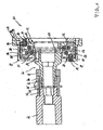
- FIG. 1 shows a drive disk 11 according to the invention is shown in longitudinal section and connected to a bolted shaft journal 41, which in turn is screwed into a hollow shaft 42 shown broken off.
- a sleeve 44 is pushed with a pinion 45, wherein splines 46 form the torque-fixed connection.
- a spacer sleeve 47 is pushed. The tension takes place via the thread pairing 48, whose pitch is to be selected so that it attracts in the preferred drive direction of the drive pulley 11.
- the drive pulley 11 comprises a hub 12 which is screwed to the shaft journal 41 by means of screwing 13.
- the hub 12 is composed of a cup-shaped part 21 and a lid-like part 22, wherein the parts are connected to each other by the screw 13.
- the hub has thus the shape of a ring cage with an inner flange 23 for screwing on the shaft journal 41.
- the two wire springs 15, 16 are supported via an inserted into the hub 12 intermediate disc 24 axially from each other, the surface of the washer with a suitable selection for damping the elastic spring movement, which takes the form of widening or contracting.
- the hub 12 two support plates 25, 26 are further inserted, via which the springs 15, 16 are each supported axially in the hub 12. These support discs 25, 26 can be used to influence the damping of the elastic spring movement.
- The-disc rim 14 also consists of a napfert part 27 and a lid-like part 28, which are connected to each other via screw 29. The disc rim 14 encloses the hub 12 in each case at the end and on the circumference.
- friction-reducing sliding discs 31, 32 are arranged, which can also serve to define or influence the damping properties of the drive pulley 11.
- a sliding or friction sleeve 33 is arranged, which serves for a play-free support between disc rim 14 and hub 12, on the other hand influencing and selecting the damping properties of the entire drive pulley.
- the inner not dargesteitten ends of the wire springs 15, 16 are each in the circumferential direction form-fitting on the hub 12 from.
- the two springs should be installed in against each other biased state.
- the drive pulley 11 is shown as a single part, wherein like details are identified by the same reference numerals as in the preceding figure.
- the foregoing description is referred to.
- two opposing slots 35, 36 are provided in the hub 12, through which the fixed in the bores 19, 20 ends 17, 18 of the wire springs 15, 16 pass through, without the relative rotational movement between the hub 12 and disk rim 14 to hinder.
- the respective inner ends of the wire springs 15,16 are truncated cut and are based on radial stops 37, 38 of the hub 12, which are expressed from sheet metal. In this case, both wire springs should be biased against each other, ie in each case radially spread apart from their relaxed starting position.
- FIG. 4 shows a drive disk 11 'according to the invention in longitudinal section.
- the drive pulley 11 ' comprises a hub 12', which can be screwed to a shaft journal by means of screwing. It further comprises a disc rim 14 ', which is connected to the hub 12' via two spirally wound wire springs 15 ', 16' torsionally elastic.
- the wire springs 15 ', 16' are spirally wound in more than one turn and can each be supported in a form-fitting manner on the pulley rim 14 with one end in rotation.
- the hub 12 ' is composed of a cup-shaped part 21' and a ring-lid-shaped part 22 ', wherein the parts are connected by axial compression to a press fit axially and rotationally fixed to each other.
- the lid-shaped part 22 ' is in this case pushed onto the outside of the cup-shaped part 21'.
- the hub 12 ' in this case forms a stepped in the width annular groove 55 with mutually parallel flanks.
- the cup-shaped part 21 ' is a sheet metal part of approximately constant wall thickness but with thickened bottom, which is stepped in three and forms three cylinder sections 49, 50, 51.
- the part 21 ' is viewed from the right undercut, It is in particular as a deep-drawn part executable.
- the cup-shaped part 21 ' has a bottom 52 in the form of an inner flange, which can serve as a screw-on flange for a shaft journal.
- a spur gear teeth can be formed, which can cooperate with a corresponding spur toothing of the left subsequent shaft journal.
- An insertion opening 62 can receive a central screw.
- the cylinder portion 49 may serve as a seat for the lid-shaped part 22 '.
- the lid-shaped part 22 ' is also formed as a sheet metal part of approximately constant wall thickness, which is stepped twice and two cylinder sections 53, 54 forms The ringdekkelförmige part 22' is seen from the left undercut and can also be prepared as a deep-drawn part.
- the part 22 With the smaller-diameter cylinder portion 53, the part 22 'sits on the smallest cylinder portion 49 of the cup-shaped part 21' as already mentioned and forms with it the annular groove 55, which comprises a narrower lower part and a wider less deep part.
- the disc rim 14 ' comprises an approximately centrally formed radial guide disc 39 and a Riernensitz 34 forming cylindrical ring 40.
- the guide plate 39 in the deeper narrower part of the annular groove 55 of the hub 12' out.
- the guide disk 39 with the hub 12 ' forms two annular spaces 56, 57 for the two wire springs 15', 16 '.
- an inner rotation stop 58 for the wire spring 15 ' can be seen, which is formed from the sheet, the disc rim 14' an outer rotation stop 59 for the wire spring 16 'visible from the disc rim 14th 'is formed.
- an outer rotation stop for the wire spring 15 'and another inner rotation stop for the wire spring 16' are provided, which are not visible in the present section.
- both wire springs 15 ', 16' should be biased against each other, ie each be radially spread apart from their relaxed starting position.
- one of the springs is additionally tensioned, while the second spring relaxes without being completely relieved, ie the prestressed contact on the respective rotation stop 58, 59 is to be maintained.
- the damping takes place on the one hand on the inner material damping of the wire springs 15 ', 16' and on the other on the relative surface friction between the guide plate 39 of the disc rim 14 'and the annular groove 55 in the hub 12', adjusted by the properties and the obstruction of the sliding or friction sleeve 30 can be.
- annular absorber mass 61 is arranged, which is formed via a vulcanized damper rubber 60, torsionally vibratory with respect to the hub 12' for the eradication of high-frequency oscillations. This vibration of the shaft journal from the pulley rim 14 'can be effectively isolated.
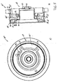
- FIG. 5 shows a drive disk 11 "according to the invention in an axial view and in a longitudinal section, the drive disk 11" comprising a hub 12 "which can be screwed to a shaft journal by means of screwing means and further comprising a disk rim 14" connected to the hub 12
- the wire springs 15 ", 16" are each spirally wound in more than one turn and can each be positively supported on the pulley rim 14 "with a cut end in rotation.
- the hub 12 " is composed of a first cup-shaped part 21" and a second cup-shaped part 22 ", wherein the parts are axially and non-rotatably connected to each other by axial compression to a press fit
- the hub 12 "in this case forms a stepped annular groove 55 with mutually parallel flanks.
- the cup-shaped part 21 is a sheet metal part of approximately constant wall thickness, which is multi-stepped and forms two Zylinderabschnitie.
- the part 21" is axially undercut free. It can be executed in particular as a deep-drawn part.
- a disk 63 is mounted centrally on the cup-shaped part 22 "for reinforcement purposes, and a through-insertion opening 62 can receive a central screw
- the inner cylinder section can serve as an outer seat for the second cup-shaped part 22".
- the second cup-shaped part 22 is likewise designed as a sheet-metal part of approximately constant wall thickness, which is multi-stepped and forms three cylindrical sections.”
- the second cup-shaped part 22 is likewise axially undercut-free and can likewise be produced as a deep-drawn part. With the smallest in diameter cylinder section sitting the part 22 "on the smallest cylinder portion of the first cup-shaped part 21" and forms with this the annular groove 55, which comprises a narrower lower part and a wider less deep part
- the disc rim 14 “comprises an approximately centrally formed radial guide disc 39 and a belt seat 34 forming cylinder ring 40.
- the guide disk 39 with the hub 12 "forms two annular spaces 56, 57 for the two wire springs 15", 16 ".” While an inner rotary stop 58 for the wire spring 15 'can be seen on the first cup-shaped part 21 “of the hub 12” the plate is formed on the other part 22 “of the hub, a further inner rotation stop 59 and two guide eyelets 70, 71 for the wire spring 16" provided These parts are each formed from the metal sheet They are found in a similar manner to the part 22 " , where there only the rotation stop 58 for the wire spring 15 "can be seen.
- both wire springs 15 ", 16” should be biased against each other, i. each be radially spread apart from their relaxed starting position.
- one of the springs is additionally tensioned, while the second spring is relaxed, without being completely relieved thereby, i.
- the system under biasing force on the respective rotation stop 58, 59 should be maintained.
- the damping takes place on the one hand on the inner material damping of the wire springs 15 “, 16” and on the other on the relative surface friction between the guide plate 39 of the disc rim 14 "and the annular groove 55 in the hub 12", by the properties and the obstruction of the sliding - or friction sleeve 30 can be adjusted.
- annular absorber mass 61 On the largest cylinder portion of the cup-shaped part 22 "is also an annular absorber mass 61 is arranged, which has a vulcanized rubber damper 60 is capable of torsional vibration with respect to the hub 12 "for the purpose of eliminating high-frequency vibrations, thereby effectively isolating vibrations of a shaft journal from the disk rim 14".
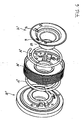
- FIG 6 the drive pulley of Figure 5 is shown in exploded view, wherein like details are designated by like reference numerals.
Landscapes
- Engineering & Computer Science (AREA)
- General Engineering & Computer Science (AREA)
- Mechanical Engineering (AREA)
- Physics & Mathematics (AREA)
- Acoustics & Sound (AREA)
- Aviation & Aerospace Engineering (AREA)
- Pulleys (AREA)
- Mechanical Operated Clutches (AREA)
- Valve Device For Special Equipments (AREA)
Applications Claiming Priority (2)
| Application Number | Priority Date | Filing Date | Title |
|---|---|---|---|
| DE102005041674 | 2005-09-01 | ||
| DE102005055034A DE102005055034B3 (de) | 2005-09-01 | 2005-11-16 | Torisionsschwingungsdämpfer oder Dekoppler mit gewickelten Drahtfedern in einer Antriebsscheibe |
Publications (2)
| Publication Number | Publication Date |
|---|---|
| EP1760355A1 true EP1760355A1 (fr) | 2007-03-07 |
| EP1760355B1 EP1760355B1 (fr) | 2009-07-01 |
Family
ID=37451166
Family Applications (1)
| Application Number | Title | Priority Date | Filing Date |
|---|---|---|---|
| EP06017389A Not-in-force EP1760355B1 (fr) | 2005-09-01 | 2006-08-22 | Amortisseur de vibrations de torsion avec des ressorts à fil dans une poulie d'entraînement |
Country Status (6)
| Country | Link |
|---|---|
| US (1) | US7815510B2 (fr) |
| EP (1) | EP1760355B1 (fr) |
| JP (1) | JP4847826B2 (fr) |
| KR (1) | KR20070026192A (fr) |
| AT (1) | ATE435383T1 (fr) |
| DE (2) | DE102005055034B3 (fr) |
Cited By (5)
| Publication number | Priority date | Publication date | Assignee | Title |
|---|---|---|---|---|
| EP2000699A2 (fr) | 2007-06-04 | 2008-12-10 | Muhr und Bender KG | Amortisseur d'oscillations de torsions ou découpleur doté de fils de fer enroulés dans un disque d'entraînement |
| EP2146111A1 (fr) | 2008-07-17 | 2010-01-20 | Carl Freudenberg KG | Dispositif d'embrayage élastique rotatif |
| WO2013124009A1 (fr) * | 2012-02-20 | 2013-08-29 | Skf B.V. | Poulie d'amortissement pour transfert de couple du type bidirectionnel |
| CN108119569A (zh) * | 2018-02-02 | 2018-06-05 | 郑州职业技术学院 | 缠带式联轴器 |
| EP2882973B1 (fr) * | 2012-08-07 | 2019-02-13 | Litens Automotive Partnership | Support d'élément découplant à forces équilibrées |
Families Citing this family (10)
| Publication number | Priority date | Publication date | Assignee | Title |
|---|---|---|---|---|
| DE102007008282A1 (de) | 2007-02-16 | 2008-08-21 | Muhr Und Bender Kg | Antriebsscheibe mit Schwingungsdämpfermitteln |
| DE102007019003A1 (de) * | 2007-04-21 | 2008-10-23 | Zf Friedrichshafen Ag | Lüfterantriebs-Übertragungseinrichtung |
| DE102008026026B4 (de) * | 2008-05-30 | 2016-01-21 | Hasse & Wrede Gmbh | Schwingungsentkoppelte Riemenscheibe |
| DE102008031419A1 (de) | 2008-07-04 | 2010-01-14 | Muhr Und Bender Kg | Drehschwingungsdämpfer |
| US8272982B2 (en) | 2008-07-09 | 2012-09-25 | Ct Drives, Llc | Cam damped pulley for rotary devices |
| US10052122B2 (en) | 2014-01-17 | 2018-08-21 | Cardiovascular Systems, Inc. | Spin-to-open atherectomy device with electric motor control |
| WO2016069260A1 (fr) | 2014-10-29 | 2016-05-06 | Borgwarner Inc. | Roue dentée élastique en torsion dotée d'un mécanisme de blocage |
| EP3271615B1 (fr) * | 2015-03-20 | 2021-08-18 | Dayco Europe S.R.L. | Poulie filtrante comprenant un dispositif d'amortissement amélioré |
| US20200217409A1 (en) * | 2019-01-09 | 2020-07-09 | Gates Corporation | Isolator |
| DE102019108656B4 (de) | 2019-04-03 | 2022-02-03 | Schaeffler Technologies AG & Co. KG | Verfahren zur Montage einer Schlingbandfeder |
Citations (2)
| Publication number | Priority date | Publication date | Assignee | Title |
|---|---|---|---|---|
| US1985296A (en) * | 1930-04-30 | 1934-12-25 | Continental Motors Corp | Engine |
| US4257500A (en) * | 1978-05-12 | 1981-03-24 | Sulzer Brothers Limited | Hand drive for coupling to a rotatable shaft |
Family Cites Families (8)
| Publication number | Priority date | Publication date | Assignee | Title |
|---|---|---|---|---|
| US1472782A (en) * | 1920-01-29 | 1923-11-06 | Albert E Barber | Shaft coupling |
| US3726133A (en) * | 1971-07-13 | 1973-04-10 | Gen Motors Corp | Flexible torque transmitting unit |
| DE3820189A1 (de) * | 1988-03-17 | 1989-09-28 | Heinz Backers | Vorrichtung zur drehmomentuebertragenden verbindung mehrerer (maschinen-)elemente |
| GB9420741D0 (en) * | 1994-10-14 | 1994-11-30 | Litens Automotive Inc | Crankshaft decoupler |
| DE19749421C2 (de) * | 1997-11-07 | 2000-08-10 | Pahl Gummi Asbest | Verfahren zur Herstellung eines Drehschwingungsdämpfers |
| ITTO20010739A1 (it) * | 2001-07-26 | 2003-01-26 | Diantel Corp N V | Gruppo di puleggia, particolarmente per un motore a combustione interna. |
| MXPA04012817A (es) * | 2002-07-26 | 2005-03-31 | Litens Automotive | Polea de desacoplador de alternador de sobremarcha con resorte de alambre desnudo y lubricacion de grasa. |
| US7591357B2 (en) * | 2003-02-04 | 2009-09-22 | John Antchak | Crankshaft torque modulator |
-
2005
- 2005-11-16 DE DE102005055034A patent/DE102005055034B3/de not_active Expired - Fee Related
-
2006
- 2006-08-22 AT AT06017389T patent/ATE435383T1/de not_active IP Right Cessation
- 2006-08-22 DE DE502006004106T patent/DE502006004106D1/de active Active
- 2006-08-22 EP EP06017389A patent/EP1760355B1/fr not_active Not-in-force
- 2006-08-30 JP JP2006234431A patent/JP4847826B2/ja not_active Expired - Fee Related
- 2006-08-31 KR KR1020060083486A patent/KR20070026192A/ko not_active Application Discontinuation
- 2006-08-31 US US11/514,066 patent/US7815510B2/en not_active Expired - Fee Related
Patent Citations (2)
| Publication number | Priority date | Publication date | Assignee | Title |
|---|---|---|---|---|
| US1985296A (en) * | 1930-04-30 | 1934-12-25 | Continental Motors Corp | Engine |
| US4257500A (en) * | 1978-05-12 | 1981-03-24 | Sulzer Brothers Limited | Hand drive for coupling to a rotatable shaft |
Cited By (8)
| Publication number | Priority date | Publication date | Assignee | Title |
|---|---|---|---|---|
| EP2000699A2 (fr) | 2007-06-04 | 2008-12-10 | Muhr und Bender KG | Amortisseur d'oscillations de torsions ou découpleur doté de fils de fer enroulés dans un disque d'entraînement |
| DE102007026195A1 (de) | 2007-06-04 | 2008-12-11 | Muhr Und Bender Kg | Torsionsschwingungsdämpfer oder Dekoppler mit gewickelten Drahtfedern in einer Antriebsscheibe |
| EP2000699A3 (fr) * | 2007-06-04 | 2010-09-15 | Muhr und Bender KG | Amortisseur d'oscillations de torsions ou découpleur doté de fils de fer enroulés dans un disque d'entraînement |
| EP2146111A1 (fr) | 2008-07-17 | 2010-01-20 | Carl Freudenberg KG | Dispositif d'embrayage élastique rotatif |
| WO2013124009A1 (fr) * | 2012-02-20 | 2013-08-29 | Skf B.V. | Poulie d'amortissement pour transfert de couple du type bidirectionnel |
| EP2882973B1 (fr) * | 2012-08-07 | 2019-02-13 | Litens Automotive Partnership | Support d'élément découplant à forces équilibrées |
| CN108119569A (zh) * | 2018-02-02 | 2018-06-05 | 郑州职业技术学院 | 缠带式联轴器 |
| CN108119569B (zh) * | 2018-02-02 | 2024-02-02 | 郑州职业技术学院 | 缠带式联轴器 |
Also Published As
| Publication number | Publication date |
|---|---|
| US20070060395A1 (en) | 2007-03-15 |
| US7815510B2 (en) | 2010-10-19 |
| ATE435383T1 (de) | 2009-07-15 |
| JP2007064485A (ja) | 2007-03-15 |
| JP4847826B2 (ja) | 2011-12-28 |
| DE502006004106D1 (de) | 2009-08-13 |
| KR20070026192A (ko) | 2007-03-08 |
| EP1760355B1 (fr) | 2009-07-01 |
| DE102005055034B3 (de) | 2007-02-08 |
Similar Documents
| Publication | Publication Date | Title |
|---|---|---|
| EP1760355B1 (fr) | Amortisseur de vibrations de torsion avec des ressorts à fil dans une poulie d'entraînement | |
| EP2000699B1 (fr) | Amortisseur d'oscillations de torsions ou découpleur doté de fils de fer enroulés dans un disque d'entraînement | |
| DE102006028552B4 (de) | Kupplungseinrichtung mit Kupplungsscheibe | |
| DE69928624T2 (de) | Torsionsnachgiebiges und gedämpftes Zahnkettentriebwerk mit Positionsanschlag | |
| DE3218192C2 (fr) | ||
| EP1626199B1 (fr) | Amortisseur de vibrations torsionelles | |
| EP1780434A2 (fr) | Dispositif d'embrayage | |
| DE19840664A1 (de) | Kolbenmotor mit Drehschwingungstilger sowie Drehschwingungstilger für einen Kolbenmotor | |
| DE4225304A1 (de) | Scheibenfoermiges bauteil | |
| DE8103147U1 (de) | Dämpfungsscheibe für Drehmomentübertragung | |
| DE102007058018A1 (de) | Triebrad | |
| DE60205242T2 (de) | Vorrichtung zur isolation von drehmomentschwingungen | |
| EP0863330B1 (fr) | Amortisseur mécanique de vibrations de torsion | |
| DE102008061589A1 (de) | Kupplungsscheibe | |
| DE19949206B4 (de) | Kolbenmotor mit Drehschwingungstilger sowie Drehschwingungstilger für einen Kolbenmotor | |
| DE4303371B4 (de) | Drehschwingungsdämpfer, insbesondere Doppel-Dämpfungsrad und Kupplungsscheibe für Kraftfahrzeuge | |
| EP1752682A1 (fr) | Amortisseur ou découpleur de vibrations torsionelles pour un disque entraîné par un ressort de torsion monté dans un arbre creux | |
| DE102010005600A1 (de) | Drehschwingungsdämpfer | |
| DE112015004974T5 (de) | Schwingungsdämpfungsvorrichtung vom Typ Trägheitsdämpfer | |
| EP1801460B1 (fr) | Unité motrice ayant un composant moteur interne et un composant moteur externe | |
| EP2141384A2 (fr) | Amortisseur de vibrations de torsions | |
| DE102005016803A1 (de) | Harmonic Drive Getriebe | |
| DE102015118465A1 (de) | Pendeldämpfungsvorrichtung für eine kraftfahrzeug-drehmomentübertragungsvorrichtung | |
| DE19932967C2 (de) | Dämpfungsvorrichtung | |
| DE19711145B4 (de) | Torsionsdämpfer mit Zwischenscheibe, insbesondere für Kraftfahrzeuge |
Legal Events
| Date | Code | Title | Description |
|---|---|---|---|
| PUAI | Public reference made under article 153(3) epc to a published international application that has entered the european phase |
Free format text: ORIGINAL CODE: 0009012 |
|
| AK | Designated contracting states |
Kind code of ref document: A1 Designated state(s): AT BE BG CH CY CZ DE DK EE ES FI FR GB GR HU IE IS IT LI LT LU LV MC NL PL PT RO SE SI SK TR |
|
| AX | Request for extension of the european patent |
Extension state: AL BA HR MK YU |
|
| 17P | Request for examination filed |
Effective date: 20070405 |
|
| 17Q | First examination report despatched |
Effective date: 20070514 |
|
| AKX | Designation fees paid |
Designated state(s): AT BE BG CH CY CZ DE DK EE ES FI FR GB GR HU IE IS IT LI LT LU LV MC NL PL PT RO SE SI SK TR |
|
| GRAP | Despatch of communication of intention to grant a patent |
Free format text: ORIGINAL CODE: EPIDOSNIGR1 |
|
| GRAS | Grant fee paid |
Free format text: ORIGINAL CODE: EPIDOSNIGR3 |
|
| GRAA | (expected) grant |
Free format text: ORIGINAL CODE: 0009210 |
|
| AK | Designated contracting states |
Kind code of ref document: B1 Designated state(s): AT BE BG CH CY CZ DE DK EE ES FI FR GB GR HU IE IS IT LI LT LU LV MC NL PL PT RO SE SI SK TR |
|
| REG | Reference to a national code |
Ref country code: GB Ref legal event code: FG4D Free format text: NOT ENGLISH |
|
| REG | Reference to a national code |
Ref country code: CH Ref legal event code: EP |
|
| REG | Reference to a national code |
Ref country code: IE Ref legal event code: FG4D |
|
| REF | Corresponds to: |
Ref document number: 502006004106 Country of ref document: DE Date of ref document: 20090813 Kind code of ref document: P |
|
| PG25 | Lapsed in a contracting state [announced via postgrant information from national office to epo] |
Ref country code: SI Free format text: LAPSE BECAUSE OF FAILURE TO SUBMIT A TRANSLATION OF THE DESCRIPTION OR TO PAY THE FEE WITHIN THE PRESCRIBED TIME-LIMIT Effective date: 20090701 |
|
| NLV1 | Nl: lapsed or annulled due to failure to fulfill the requirements of art. 29p and 29m of the patents act | ||
| PG25 | Lapsed in a contracting state [announced via postgrant information from national office to epo] |
Ref country code: FI Free format text: LAPSE BECAUSE OF FAILURE TO SUBMIT A TRANSLATION OF THE DESCRIPTION OR TO PAY THE FEE WITHIN THE PRESCRIBED TIME-LIMIT Effective date: 20090701 Ref country code: IS Free format text: LAPSE BECAUSE OF FAILURE TO SUBMIT A TRANSLATION OF THE DESCRIPTION OR TO PAY THE FEE WITHIN THE PRESCRIBED TIME-LIMIT Effective date: 20091101 Ref country code: EE Free format text: LAPSE BECAUSE OF FAILURE TO SUBMIT A TRANSLATION OF THE DESCRIPTION OR TO PAY THE FEE WITHIN THE PRESCRIBED TIME-LIMIT Effective date: 20090701 Ref country code: ES Free format text: LAPSE BECAUSE OF FAILURE TO SUBMIT A TRANSLATION OF THE DESCRIPTION OR TO PAY THE FEE WITHIN THE PRESCRIBED TIME-LIMIT Effective date: 20091012 Ref country code: LT Free format text: LAPSE BECAUSE OF FAILURE TO SUBMIT A TRANSLATION OF THE DESCRIPTION OR TO PAY THE FEE WITHIN THE PRESCRIBED TIME-LIMIT Effective date: 20090701 Ref country code: SE Free format text: LAPSE BECAUSE OF FAILURE TO SUBMIT A TRANSLATION OF THE DESCRIPTION OR TO PAY THE FEE WITHIN THE PRESCRIBED TIME-LIMIT Effective date: 20090701 |
|
| REG | Reference to a national code |
Ref country code: IE Ref legal event code: FD4D |
|
| PG25 | Lapsed in a contracting state [announced via postgrant information from national office to epo] |
Ref country code: LV Free format text: LAPSE BECAUSE OF FAILURE TO SUBMIT A TRANSLATION OF THE DESCRIPTION OR TO PAY THE FEE WITHIN THE PRESCRIBED TIME-LIMIT Effective date: 20090701 Ref country code: PL Free format text: LAPSE BECAUSE OF FAILURE TO SUBMIT A TRANSLATION OF THE DESCRIPTION OR TO PAY THE FEE WITHIN THE PRESCRIBED TIME-LIMIT Effective date: 20090701 Ref country code: NL Free format text: LAPSE BECAUSE OF FAILURE TO SUBMIT A TRANSLATION OF THE DESCRIPTION OR TO PAY THE FEE WITHIN THE PRESCRIBED TIME-LIMIT Effective date: 20090701 |
|
| BERE | Be: lapsed |
Owner name: MUHR UND BENDER K.G. Effective date: 20090831 |
|
| PG25 | Lapsed in a contracting state [announced via postgrant information from national office to epo] |
Ref country code: MC Free format text: LAPSE BECAUSE OF NON-PAYMENT OF DUE FEES Effective date: 20090831 Ref country code: PT Free format text: LAPSE BECAUSE OF FAILURE TO SUBMIT A TRANSLATION OF THE DESCRIPTION OR TO PAY THE FEE WITHIN THE PRESCRIBED TIME-LIMIT Effective date: 20091102 Ref country code: BG Free format text: LAPSE BECAUSE OF FAILURE TO SUBMIT A TRANSLATION OF THE DESCRIPTION OR TO PAY THE FEE WITHIN THE PRESCRIBED TIME-LIMIT Effective date: 20091001 |
|
| PG25 | Lapsed in a contracting state [announced via postgrant information from national office to epo] |
Ref country code: IE Free format text: LAPSE BECAUSE OF FAILURE TO SUBMIT A TRANSLATION OF THE DESCRIPTION OR TO PAY THE FEE WITHIN THE PRESCRIBED TIME-LIMIT Effective date: 20090701 Ref country code: RO Free format text: LAPSE BECAUSE OF FAILURE TO SUBMIT A TRANSLATION OF THE DESCRIPTION OR TO PAY THE FEE WITHIN THE PRESCRIBED TIME-LIMIT Effective date: 20090701 Ref country code: DK Free format text: LAPSE BECAUSE OF FAILURE TO SUBMIT A TRANSLATION OF THE DESCRIPTION OR TO PAY THE FEE WITHIN THE PRESCRIBED TIME-LIMIT Effective date: 20090701 Ref country code: CZ Free format text: LAPSE BECAUSE OF FAILURE TO SUBMIT A TRANSLATION OF THE DESCRIPTION OR TO PAY THE FEE WITHIN THE PRESCRIBED TIME-LIMIT Effective date: 20090701 |
|
| PLBE | No opposition filed within time limit |
Free format text: ORIGINAL CODE: 0009261 |
|
| STAA | Information on the status of an ep patent application or granted ep patent |
Free format text: STATUS: NO OPPOSITION FILED WITHIN TIME LIMIT |
|
| PG25 | Lapsed in a contracting state [announced via postgrant information from national office to epo] |
Ref country code: SK Free format text: LAPSE BECAUSE OF FAILURE TO SUBMIT A TRANSLATION OF THE DESCRIPTION OR TO PAY THE FEE WITHIN THE PRESCRIBED TIME-LIMIT Effective date: 20090701 |
|
| 26N | No opposition filed |
Effective date: 20100406 |
|
| PG25 | Lapsed in a contracting state [announced via postgrant information from national office to epo] |
Ref country code: BE Free format text: LAPSE BECAUSE OF NON-PAYMENT OF DUE FEES Effective date: 20090831 |
|
| PG25 | Lapsed in a contracting state [announced via postgrant information from national office to epo] |
Ref country code: GR Free format text: LAPSE BECAUSE OF FAILURE TO SUBMIT A TRANSLATION OF THE DESCRIPTION OR TO PAY THE FEE WITHIN THE PRESCRIBED TIME-LIMIT Effective date: 20091002 |
|
| PG25 | Lapsed in a contracting state [announced via postgrant information from national office to epo] |
Ref country code: AT Free format text: LAPSE BECAUSE OF NON-PAYMENT OF DUE FEES Effective date: 20090822 |
|
| REG | Reference to a national code |
Ref country code: CH Ref legal event code: PL |
|
| PG25 | Lapsed in a contracting state [announced via postgrant information from national office to epo] |
Ref country code: LI Free format text: LAPSE BECAUSE OF NON-PAYMENT OF DUE FEES Effective date: 20100831 Ref country code: CH Free format text: LAPSE BECAUSE OF NON-PAYMENT OF DUE FEES Effective date: 20100831 Ref country code: LU Free format text: LAPSE BECAUSE OF NON-PAYMENT OF DUE FEES Effective date: 20090822 |
|
| PG25 | Lapsed in a contracting state [announced via postgrant information from national office to epo] |
Ref country code: HU Free format text: LAPSE BECAUSE OF FAILURE TO SUBMIT A TRANSLATION OF THE DESCRIPTION OR TO PAY THE FEE WITHIN THE PRESCRIBED TIME-LIMIT Effective date: 20100102 |
|
| PG25 | Lapsed in a contracting state [announced via postgrant information from national office to epo] |
Ref country code: TR Free format text: LAPSE BECAUSE OF FAILURE TO SUBMIT A TRANSLATION OF THE DESCRIPTION OR TO PAY THE FEE WITHIN THE PRESCRIBED TIME-LIMIT Effective date: 20090701 |
|
| PG25 | Lapsed in a contracting state [announced via postgrant information from national office to epo] |
Ref country code: CY Free format text: LAPSE BECAUSE OF FAILURE TO SUBMIT A TRANSLATION OF THE DESCRIPTION OR TO PAY THE FEE WITHIN THE PRESCRIBED TIME-LIMIT Effective date: 20090701 |
|
| PGFP | Annual fee paid to national office [announced via postgrant information from national office to epo] |
Ref country code: DE Payment date: 20130812 Year of fee payment: 8 |
|
| PGFP | Annual fee paid to national office [announced via postgrant information from national office to epo] |
Ref country code: FR Payment date: 20130725 Year of fee payment: 8 Ref country code: GB Payment date: 20130816 Year of fee payment: 8 |
|
| PGFP | Annual fee paid to national office [announced via postgrant information from national office to epo] |
Ref country code: IT Payment date: 20130726 Year of fee payment: 8 |
|
| REG | Reference to a national code |
Ref country code: DE Ref legal event code: R119 Ref document number: 502006004106 Country of ref document: DE |
|
| GBPC | Gb: european patent ceased through non-payment of renewal fee |
Effective date: 20140822 |
|
| PG25 | Lapsed in a contracting state [announced via postgrant information from national office to epo] |
Ref country code: IT Free format text: LAPSE BECAUSE OF NON-PAYMENT OF DUE FEES Effective date: 20140822 |
|
| REG | Reference to a national code |
Ref country code: DE Ref legal event code: R119 Ref document number: 502006004106 Country of ref document: DE Effective date: 20150303 |
|
| REG | Reference to a national code |
Ref country code: FR Ref legal event code: ST Effective date: 20150430 |
|
| PG25 | Lapsed in a contracting state [announced via postgrant information from national office to epo] |
Ref country code: GB Free format text: LAPSE BECAUSE OF NON-PAYMENT OF DUE FEES Effective date: 20140822 Ref country code: DE Free format text: LAPSE BECAUSE OF NON-PAYMENT OF DUE FEES Effective date: 20150303 |
|
| PG25 | Lapsed in a contracting state [announced via postgrant information from national office to epo] |
Ref country code: FR Free format text: LAPSE BECAUSE OF NON-PAYMENT OF DUE FEES Effective date: 20140901 |