EP1759804A1 - Laser processing machine comprising a nozzle polishing device - Google Patents
Laser processing machine comprising a nozzle polishing device Download PDFInfo
- Publication number
- EP1759804A1 EP1759804A1 EP06405238A EP06405238A EP1759804A1 EP 1759804 A1 EP1759804 A1 EP 1759804A1 EP 06405238 A EP06405238 A EP 06405238A EP 06405238 A EP06405238 A EP 06405238A EP 1759804 A1 EP1759804 A1 EP 1759804A1
- Authority
- EP
- European Patent Office
- Prior art keywords
- nozzle
- axis
- laser processing
- polishing device
- processing
- Prior art date
- Legal status (The legal status is an assumption and is not a legal conclusion. Google has not performed a legal analysis and makes no representation as to the accuracy of the status listed.)
- Granted
Links
Images




Classifications
-
- B—PERFORMING OPERATIONS; TRANSPORTING
- B23—MACHINE TOOLS; METAL-WORKING NOT OTHERWISE PROVIDED FOR
- B23K—SOLDERING OR UNSOLDERING; WELDING; CLADDING OR PLATING BY SOLDERING OR WELDING; CUTTING BY APPLYING HEAT LOCALLY, e.g. FLAME CUTTING; WORKING BY LASER BEAM
- B23K37/00—Auxiliary devices or processes, not specially adapted for a procedure covered by only one of the other main groups of this subclass
- B23K37/04—Auxiliary devices or processes, not specially adapted for a procedure covered by only one of the other main groups of this subclass for holding or positioning work
- B23K37/0408—Auxiliary devices or processes, not specially adapted for a procedure covered by only one of the other main groups of this subclass for holding or positioning work for planar work
-
- B—PERFORMING OPERATIONS; TRANSPORTING
- B23—MACHINE TOOLS; METAL-WORKING NOT OTHERWISE PROVIDED FOR
- B23K—SOLDERING OR UNSOLDERING; WELDING; CLADDING OR PLATING BY SOLDERING OR WELDING; CUTTING BY APPLYING HEAT LOCALLY, e.g. FLAME CUTTING; WORKING BY LASER BEAM
- B23K26/00—Working by laser beam, e.g. welding, cutting or boring
- B23K26/08—Devices involving relative movement between laser beam and workpiece
- B23K26/0869—Devices involving movement of the laser head in at least one axial direction
- B23K26/0876—Devices involving movement of the laser head in at least one axial direction in at least two axial directions
- B23K26/0884—Devices involving movement of the laser head in at least one axial direction in at least two axial directions in at least three axial directions, e.g. manipulators, robots
-
- B—PERFORMING OPERATIONS; TRANSPORTING
- B23—MACHINE TOOLS; METAL-WORKING NOT OTHERWISE PROVIDED FOR
- B23K—SOLDERING OR UNSOLDERING; WELDING; CLADDING OR PLATING BY SOLDERING OR WELDING; CUTTING BY APPLYING HEAT LOCALLY, e.g. FLAME CUTTING; WORKING BY LASER BEAM
- B23K26/00—Working by laser beam, e.g. welding, cutting or boring
- B23K26/14—Working by laser beam, e.g. welding, cutting or boring using a fluid stream, e.g. a jet of gas, in conjunction with the laser beam; Nozzles therefor
- B23K26/1462—Nozzles; Features related to nozzles
- B23K26/1482—Detachable nozzles, e.g. exchangeable or provided with breakaway lines
-
- B—PERFORMING OPERATIONS; TRANSPORTING
- B23—MACHINE TOOLS; METAL-WORKING NOT OTHERWISE PROVIDED FOR
- B23K—SOLDERING OR UNSOLDERING; WELDING; CLADDING OR PLATING BY SOLDERING OR WELDING; CUTTING BY APPLYING HEAT LOCALLY, e.g. FLAME CUTTING; WORKING BY LASER BEAM
- B23K26/00—Working by laser beam, e.g. welding, cutting or boring
- B23K26/14—Working by laser beam, e.g. welding, cutting or boring using a fluid stream, e.g. a jet of gas, in conjunction with the laser beam; Nozzles therefor
- B23K26/1462—Nozzles; Features related to nozzles
- B23K26/1494—Maintenance of nozzles
-
- B—PERFORMING OPERATIONS; TRANSPORTING
- B23—MACHINE TOOLS; METAL-WORKING NOT OTHERWISE PROVIDED FOR
- B23K—SOLDERING OR UNSOLDERING; WELDING; CLADDING OR PLATING BY SOLDERING OR WELDING; CUTTING BY APPLYING HEAT LOCALLY, e.g. FLAME CUTTING; WORKING BY LASER BEAM
- B23K26/00—Working by laser beam, e.g. welding, cutting or boring
- B23K26/70—Auxiliary operations or equipment
- B23K26/702—Auxiliary equipment
-
- B—PERFORMING OPERATIONS; TRANSPORTING
- B23—MACHINE TOOLS; METAL-WORKING NOT OTHERWISE PROVIDED FOR
- B23K—SOLDERING OR UNSOLDERING; WELDING; CLADDING OR PLATING BY SOLDERING OR WELDING; CUTTING BY APPLYING HEAT LOCALLY, e.g. FLAME CUTTING; WORKING BY LASER BEAM
- B23K37/00—Auxiliary devices or processes, not specially adapted for a procedure covered by only one of the other main groups of this subclass
- B23K37/02—Carriages for supporting the welding or cutting element
- B23K37/0211—Carriages for supporting the welding or cutting element travelling on a guide member, e.g. rail, track
- B23K37/0235—Carriages for supporting the welding or cutting element travelling on a guide member, e.g. rail, track the guide member forming part of a portal
-
- B—PERFORMING OPERATIONS; TRANSPORTING
- B24—GRINDING; POLISHING
- B24B—MACHINES, DEVICES, OR PROCESSES FOR GRINDING OR POLISHING; DRESSING OR CONDITIONING OF ABRADING SURFACES; FEEDING OF GRINDING, POLISHING, OR LAPPING AGENTS
- B24B27/00—Other grinding machines or devices
- B24B27/033—Other grinding machines or devices for grinding a surface for cleaning purposes, e.g. for descaling or for grinding off flaws in the surface
-
- B—PERFORMING OPERATIONS; TRANSPORTING
- B24—GRINDING; POLISHING
- B24B—MACHINES, DEVICES, OR PROCESSES FOR GRINDING OR POLISHING; DRESSING OR CONDITIONING OF ABRADING SURFACES; FEEDING OF GRINDING, POLISHING, OR LAPPING AGENTS
- B24B9/00—Machines or devices designed for grinding edges or bevels on work or for removing burrs; Accessories therefor
- B24B9/007—Machines or devices designed for grinding edges or bevels on work or for removing burrs; Accessories therefor for end faces of tubes
Definitions
- the present invention provides means for unattended operation for a long time of period by removing contaminants with a cutting tool such as a grinding tool when contaminants adhere to a nozzle of a laser processing machine.
- Patent Document 1 discloses a machine having a brush for removing dross which adheres to a nozzle.
- some melt (sputtered material) in the processing flies above a work surface, due to the pressure of an assist gas for example, and adheres to a bottom surface of a nozzle, which makes a gap between the bottom surface of the nozzle and the upper work surface non-uniform.
- the patent document above described discloses a copy operation to control the position of a laser processing tool in the Z axis direction which records a Z axis coordinate by bring a nozzle into contact with a touch sensor.
- the patent document also discloses a method for removing contaminants such as dross adhering to a nozzle by bringing a nozzle tip to a brush so that a circular motion of the nozzle removes the contaminants.
- the present invention provides a device having a polishing device to polish a nozzle without moving the nozzle.
- a laser processing machine comprises: a bed; a pallet disposed on the bed to support a work; a column which is controlled to move along the X axis, the X axis being the longitudinal axis of the bed; a saddle which is supported by the column and is controlled to move along the Y axis, the Y axis being perpendicularly crossing the X axis; a processing head which is supported by the saddle and is controlled to move along the Z axis, the Z axis being perpendicular to a plane defined by the X axis and the Y axis.
- the present invention provides a nozzle polishing device comprising a melt removing device for removing melt with a grinding tool, the melt adhering to a tip nozzle of a laser processing tool mounted to the processing head as basic means.
- a copy function is stabilized so that a gap between a bottom surface of a nozzle and an upper work surface becomes uniform, imperfections in a processing such as dross forming are not caused, which stabilizes the processing and makes an unattended operation for a long time of period possible.
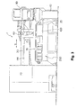
- FIG. 1 is a perspective view to generally show a laser processing machine according to the present invention.
- FIG. 2 is a plan view of the same
- FIG. 3 is an elevational view of the same
- FIG. 4 is a perspective view to show the main parts of the same
- FIG. 5 is a side view to show the main parts of the same.
- a laser processing machine which is generally denoted by reference numeral 1, has a bed 10 and a pallet (table) 20 disposed on the bed 10, and a sheet of a work W 1 is rested on the pallet 20.
- a pallet exchanging device 12 is arranged adjacent to the bed 10 in the longitudinal direction of the bed 10, having a pallet 20a on which a work W 2 is rested for a subsequent processing.
- a pair of guide rails 34 are provided along both of the longitudinal sides of the bed 10, and a column 30 is mounted on the guide rails 34 to be movable in the X axis direction.
- the column 30 may move in the X axis direction driven by for example a linear motor which is formed with a stator provided to the guide rails 34 and movers provided to translation guides 32.
- the column 30 includes a guide rail 44 provided along the Y axis which is perpendicularly crossing the X axis to mount a saddle 40 movable in the Y axis direction.
- the saddle 40 includes a translation guide 42 which engages with the guide rail 44, which forms a linear motor between the guide rail 44 and the translation guide 42.
- the saddle 40 includes a guide rail in the Z axis direction which is perpendicular to a plane defined by the X axis and the Y axis, and a processing head 50 is mounted to the guide rail movable along the Z axis.
- the processing head 50 includes an optical system into which a laser beam is introduced from a laser emitting device 72.
- a laser processing tool 60 is exchangeably mounted to the processing head 50.
- a processing area is covered with a cover 90 for safety.
- An electric cabinet 70 and the laser emitting device 72 are arranged adjacent to the bed 10.
- a control panel 80 through which an operator issues commands for various operations is disposed at one end of a longitudinal side of the bed 10.
- a setup station 100 for a laser processing tool is equipped with.
- FIG. 6 is an elevational view to show the setup station 100 for a laser processing tool as seen from the table
- FIG. 7 is a plan view to show the same.
- the setup station 100 for a laser processing tool includes: a tool station 200 equipped with a tool change magazine for laser processing tools having a torch and a nozzle respectively; and a nozzle station 300 equipped with a nozzle change magazine for nozzles of the laser processing tools.
- FIG. 8 is a view to illustrate a nozzle polishing device according to the present invention.
- a nozzle polishing device 600 includes a processing head 610, and the processing head 610 drives a processing tool 620 which is a formed grindstone.
- the processing tool 620 may be a formed grindstone having a processing surface 622 corresponding to the outer configuration of a nozzle 65.
- a laser processing head equipped with the nozzle 65 to which sputtered material S 1 adheres is positioned above the nozzle polishing device 600, and the entire laser processing tool is lowered in the Z axis direction.
- FIG. 10 is a view to illustrate another example of a nozzle polishing device.
- a nozzle polishing device 650 has a frame 652 and a processing head 660 which is supported with bolts 654 in the frame 652.
- the processing head 660 is equipped with a motor therein, and has a rotation shaft 662 mounted with a cylindrical grindstone 670.
- the cylindrical grindstone 670 has an upper surface 672 which is used to polish and remove contaminants such as dross adhering to a bottom end surface of the nozzle 65.
- FIG. 11 is a view to illustrate another example of a nozzle polishing device according to the present invention.
- a nozzle 65a includes a flange portion 65b, and sputtered material S 1 adhering to the flange portion 65b sometimes causes imperfections in a processing.
- a nozzle polishing device 650 is used so that an upper surface 672 of a cylindrical grindstone 670 is brought into contact with the flange portions 65b of the nozzle 65a to remove the sputtered material S 1 .
- the nozzle polishing device 650 is moved in circle along the flange portions 65b in the direction shown by an arrow R 2 to complete the removal of the sputtered material S 1 .
- a grindstone is used as a polishing tool for a nozzle, but of course, other tools such as a carbide tool may be used as needed.
Landscapes
- Engineering & Computer Science (AREA)
- Physics & Mathematics (AREA)
- Optics & Photonics (AREA)
- Mechanical Engineering (AREA)
- Plasma & Fusion (AREA)
- Robotics (AREA)
- Laser Beam Processing (AREA)
Abstract
Description
- The present invention provides means for unattended operation for a long time of period by removing contaminants with a cutting tool such as a grinding tool when contaminants adhere to a nozzle of a laser processing machine.
- In a conventional laser processing machine, predetermined standard processing conditions defined by materials and thicknesses are registered in a numeral count device (NC device). During a laser processing according to the processing conditions, any trouble in the function of a nozzle mounted to the tip of a processing torch causes imperfections in the processing such as dross forming. In order to maintain the optimal processing conditions, an operator needs to detect such a trouble of a nozzle in ahead, stop a machine, and examine the nozzle for abnormality, and when a trouble is recognized, the nozzle should be manually changed or be cleaned, any deformation of the nozzle should be adjusted, or the processing conditions should be changed.
Japanese Patent Laid-Open Publication No. 2001-150173 - During a laser processing, some melt (sputtered material) in the processing flies above a work surface, due to the pressure of an assist gas for example, and adheres to a bottom surface of a nozzle, which makes a gap between the bottom surface of the nozzle and the upper work surface non-uniform. The patent document above described discloses a copy operation to control the position of a laser processing tool in the Z axis direction which records a Z axis coordinate by bring a nozzle into contact with a touch sensor. The patent document also discloses a method for removing contaminants such as dross adhering to a nozzle by bringing a nozzle tip to a brush so that a circular motion of the nozzle removes the contaminants. The present invention provides a device having a polishing device to polish a nozzle without moving the nozzle.
- A laser processing machine according to the present invention comprises: a bed; a pallet disposed on the bed to support a work; a column which is controlled to move along the X axis, the X axis being the longitudinal axis of the bed; a saddle which is supported by the column and is controlled to move along the Y axis, the Y axis being perpendicularly crossing the X axis; a processing head which is supported by the saddle and is controlled to move along the Z axis, the Z axis being perpendicular to a plane defined by the X axis and the Y axis. The present invention provides a nozzle polishing device comprising a melt removing device for removing melt with a grinding tool, the melt adhering to a tip nozzle of a laser processing tool mounted to the processing head as basic means.
- According to the present invention, because a copy function is stabilized so that a gap between a bottom surface of a nozzle and an upper work surface becomes uniform, imperfections in a processing such as dross forming are not caused, which stabilizes the processing and makes an unattended operation for a long time of period possible.
-
- FIG. 1 is a perspective view to generally show a laser processing machine according to the present invention;
- FIG. 2 is a plan view to show a laser processing machine according to the present invention;
- FIG. 3 is an elevational view to show the main parts of a laser processing machine according to the present invention;
- FIG. 4 is a perspective view to show the main parts of a laser processing machine according to the present invention;
- FIG. 5 is a side view to show the main parts of a laser processing machine according to the present invention;
- FIG. 6 is an elevational view to show a setup station for a laser processing tool;
- FIG. 7 is a plan view to show a setup station for a laser processing tool;
- FIG. 8 is a view to illustrate a nozzle polishing device;
- FIG. 9 is a view to illustrate a nozzle polishing device;
- FIG. 10 is a view to illustrate another example of a nozzle polishing device; and
- FIG. 11 is a view to illustrate another example of a nozzle polishing device.
- FIG. 1 is a perspective view to generally show a laser processing machine according to the present invention. FIG. 2 is a plan view of the same, FIG. 3 is an elevational view of the same, FIG. 4 is a perspective view to show the main parts of the same, and FIG. 5 is a side view to show the main parts of the same. A laser processing machine, which is generally denoted by reference numeral 1, has a
bed 10 and a pallet (table) 20 disposed on thebed 10, and a sheet of a work W1 is rested on thepallet 20. Apallet exchanging device 12 is arranged adjacent to thebed 10 in the longitudinal direction of thebed 10, having a pallet 20a on which a work W2 is rested for a subsequent processing. - A pair of
guide rails 34 are provided along both of the longitudinal sides of thebed 10, and acolumn 30 is mounted on theguide rails 34 to be movable in the X axis direction. - The
column 30 may move in the X axis direction driven by for example a linear motor which is formed with a stator provided to theguide rails 34 and movers provided totranslation guides 32. - The
column 30 includes aguide rail 44 provided along the Y axis which is perpendicularly crossing the X axis to mount asaddle 40 movable in the Y axis direction. Thesaddle 40 includes atranslation guide 42 which engages with theguide rail 44, which forms a linear motor between theguide rail 44 and thetranslation guide 42. - The
saddle 40 includes a guide rail in the Z axis direction which is perpendicular to a plane defined by the X axis and the Y axis, and aprocessing head 50 is mounted to the guide rail movable along the Z axis. Theprocessing head 50 includes an optical system into which a laser beam is introduced from alaser emitting device 72. - To the
processing head 50, alaser processing tool 60 is exchangeably mounted. A processing area is covered with a cover 90 for safety. Anelectric cabinet 70 and thelaser emitting device 72 are arranged adjacent to thebed 10. Acontrol panel 80 through which an operator issues commands for various operations is disposed at one end of a longitudinal side of thebed 10. At one end of thebed 10 which is close to thecontrol panel 80, asetup station 100 for a laser processing tool is equipped with. - FIG. 6 is an elevational view to show the
setup station 100 for a laser processing tool as seen from the table, and FIG. 7 is a plan view to show the same. Thesetup station 100 for a laser processing tool includes: atool station 200 equipped with a tool change magazine for laser processing tools having a torch and a nozzle respectively; and anozzle station 300 equipped with a nozzle change magazine for nozzles of the laser processing tools. - FIG. 8 is a view to illustrate a nozzle polishing device according to the present invention. A
nozzle polishing device 600 includes aprocessing head 610, and theprocessing head 610 drives aprocessing tool 620 which is a formed grindstone. Theprocessing tool 620 may be a formed grindstone having aprocessing surface 622 corresponding to the outer configuration of anozzle 65. As shown in FIG. 9, a laser processing head equipped with thenozzle 65 to which sputtered material S1 adheres is positioned above thenozzle polishing device 600, and the entire laser processing tool is lowered in the Z axis direction. Then, theprocessing tool 620 of thenozzle polishing device 600 is rotated and thenozzle 65 is brought into contact with theprocessing surface 622, thereby the sputtered material adhering to thenozzle 65 is ground and removed. FIG. 10 is a view to illustrate another example of a nozzle polishing device. Anozzle polishing device 650 has aframe 652 and aprocessing head 660 which is supported withbolts 654 in theframe 652. Theprocessing head 660 is equipped with a motor therein, and has arotation shaft 662 mounted with acylindrical grindstone 670. Thecylindrical grindstone 670 has anupper surface 672 which is used to polish and remove contaminants such as dross adhering to a bottom end surface of thenozzle 65. - FIG. 11 is a view to illustrate another example of a nozzle polishing device according to the present invention. A
nozzle 65a includes aflange portion 65b, and sputtered material S1 adhering to theflange portion 65b sometimes causes imperfections in a processing. Thus, anozzle polishing device 650 is used so that anupper surface 672 of acylindrical grindstone 670 is brought into contact with theflange portions 65b of thenozzle 65a to remove the sputtered material S1. Thenozzle polishing device 650 is moved in circle along theflange portions 65b in the direction shown by an arrow R2 to complete the removal of the sputtered material S1. - In the above examples, a grindstone is used as a polishing tool for a nozzle, but of course, other tools such as a carbide tool may be used as needed.
Claims (4)
- In a laser processing machine (1) comprising: a bed (10); a pallet (20) disposed on the bed (10) to support a work (W1); a column (30) which is controlled to move along the X axis, the X axis being the longitudinal axis of the bed (10); a saddle (40) which is supported by the column (30) and is controlled to move along the Y axis, the Y axis being perpendicularly crossing the X axis; and a processing head (50) which is supported by the saddle (40) and is controlled to move along the Z axis, the Z axis being perpendicular to a plane defined by the X axis and the Y axis,
a nozzle polishing device (600, 650) comprising a melt removing device for removing melt (S1) with a grinding tool (620, 670), the melt (S1) adhering to a tip nozzle (65, 65a) of a laser processing tool (60) mounted to the processing head (50). - The nozzle polishing device (600, 650) in a laser processing machine (1) according to claim 1, wherein the laser processing tool (60) comprises a torch having an optical system including a condenser lens, and a nozzle (65, 65a) which is exchangeably mounted to the tip of the torch.
- The nozzle polishing device (600, 650) in a laser processing machine (1) according to claim 1, wherein further comprising a formed grindstone (620, 670) which is mounted to the melt removing device.
- The nozzle polishing device (600, 650) in a laser processing machine (1) according to claim 1, wherein further comprising a plurality of melt removing devices each of which are equipped with a polishing tool corresponding to a type of a nozzle (65, 65a).
Applications Claiming Priority (1)
| Application Number | Priority Date | Filing Date | Title |
|---|---|---|---|
| JP2005249695A JP2006175580A (en) | 2004-11-29 | 2005-08-30 | Grinding device for nozzle in laser beam machine |
Publications (2)
| Publication Number | Publication Date |
|---|---|
| EP1759804A1 true EP1759804A1 (en) | 2007-03-07 |
| EP1759804B1 EP1759804B1 (en) | 2009-11-11 |
Family
ID=37460230
Family Applications (1)
| Application Number | Title | Priority Date | Filing Date |
|---|---|---|---|
| EP06405238A Not-in-force EP1759804B1 (en) | 2005-08-30 | 2006-05-31 | Laser processing machine comprising a nozzle polishing device |
Country Status (4)
| Country | Link |
|---|---|
| US (1) | US20070045258A1 (en) |
| EP (1) | EP1759804B1 (en) |
| CN (1) | CN100558496C (en) |
| DE (1) | DE602006010283D1 (en) |
Cited By (1)
| Publication number | Priority date | Publication date | Assignee | Title |
|---|---|---|---|---|
| US20220379413A1 (en) * | 2019-10-31 | 2022-12-01 | Amada Co., Ltd. | Workpiece support member for use with workpiece support table, and thermal processing machine |
Families Citing this family (4)
| Publication number | Priority date | Publication date | Assignee | Title |
|---|---|---|---|---|
| US20090076741A1 (en) * | 2007-09-19 | 2009-03-19 | Eb Associates, Inc. | Distributed system for measuring lumber in a sawmill |
| DE102013200067A1 (en) * | 2013-01-04 | 2014-07-10 | Ford-Werke Gmbh | Device for thermally coating a surface |
| DE102016209285B3 (en) * | 2016-05-30 | 2017-08-17 | Trumpf Maschinen Ag | Processing machine with a nozzle changer |
| USD850500S1 (en) * | 2016-08-31 | 2019-06-04 | Trumpf Gmbh + Co. Kg | Machine tool |
Citations (4)
| Publication number | Priority date | Publication date | Assignee | Title |
|---|---|---|---|---|
| US5091625A (en) * | 1990-02-16 | 1992-02-25 | Brother Kogyo Kabushiki Kaisha | Plasma arc cutting device having metal deposition removal function and method for removing deposition from nozzle of the plasma arc cutting device |
| US5854460A (en) * | 1996-05-07 | 1998-12-29 | Cincinnati Incorporated | Linear motor driven laser cutting machine |
| JP2001150173A (en) * | 1999-11-22 | 2001-06-05 | Amada Wasino Co Ltd | Laser beam machining method and laser beam machine |
| JP2001162376A (en) * | 1999-12-09 | 2001-06-19 | Koji Irie | Grinding fixture of welding torch |
Family Cites Families (7)
| Publication number | Priority date | Publication date | Assignee | Title |
|---|---|---|---|---|
| US4027137A (en) * | 1975-09-17 | 1977-05-31 | International Business Machines Corporation | Laser drilling nozzle |
| US4272007A (en) * | 1979-02-02 | 1981-06-09 | Steranko James J | Wire bonding system and method |
| US4593445A (en) * | 1984-11-13 | 1986-06-10 | Westinghouse Electric Corp. | Apparatus and process for refurbishing valves |
| US5304773A (en) * | 1992-02-19 | 1994-04-19 | Trumpf Inc. | Laser work station with optical sensor for calibration of guidance system |
| JP3057631B2 (en) * | 1995-11-24 | 2000-07-04 | 株式会社新川 | Cleaning method of wire bonding tool for coated wire |
| US6976909B1 (en) * | 2003-05-30 | 2005-12-20 | Hoover Bruce G | Extended sanding support |
| JP4338204B2 (en) * | 2005-03-30 | 2009-10-07 | Tdk株式会社 | Soldering method, soldering apparatus, joining method and joining apparatus |
-
2006
- 2006-05-25 US US11/420,278 patent/US20070045258A1/en not_active Abandoned
- 2006-05-31 DE DE602006010283T patent/DE602006010283D1/en active Active
- 2006-05-31 EP EP06405238A patent/EP1759804B1/en not_active Not-in-force
- 2006-06-05 CN CNB2006100887646A patent/CN100558496C/en not_active Expired - Fee Related
Patent Citations (4)
| Publication number | Priority date | Publication date | Assignee | Title |
|---|---|---|---|---|
| US5091625A (en) * | 1990-02-16 | 1992-02-25 | Brother Kogyo Kabushiki Kaisha | Plasma arc cutting device having metal deposition removal function and method for removing deposition from nozzle of the plasma arc cutting device |
| US5854460A (en) * | 1996-05-07 | 1998-12-29 | Cincinnati Incorporated | Linear motor driven laser cutting machine |
| JP2001150173A (en) * | 1999-11-22 | 2001-06-05 | Amada Wasino Co Ltd | Laser beam machining method and laser beam machine |
| JP2001162376A (en) * | 1999-12-09 | 2001-06-19 | Koji Irie | Grinding fixture of welding torch |
Non-Patent Citations (1)
| Title |
|---|
| DATABASE WPI Week 200160, Derwent World Patents Index; AN 2001-539046, XP002410461 * |
Cited By (1)
| Publication number | Priority date | Publication date | Assignee | Title |
|---|---|---|---|---|
| US20220379413A1 (en) * | 2019-10-31 | 2022-12-01 | Amada Co., Ltd. | Workpiece support member for use with workpiece support table, and thermal processing machine |
Also Published As
| Publication number | Publication date |
|---|---|
| CN1923428A (en) | 2007-03-07 |
| DE602006010283D1 (en) | 2009-12-24 |
| CN100558496C (en) | 2009-11-11 |
| EP1759804B1 (en) | 2009-11-11 |
| US20070045258A1 (en) | 2007-03-01 |
Similar Documents
| Publication | Publication Date | Title |
|---|---|---|
| US7159294B2 (en) | Burr removal apparatus for laser beam machine | |
| US6327761B1 (en) | Apparatus for machining a flat metallic workpiece | |
| CN100404190C (en) | Nozzle exchange box in laser processing machine | |
| JP7220035B2 (en) | band saw | |
| EP1600241B1 (en) | Focus adjuster for laser beam machine | |
| US20070045258A1 (en) | Nozzle polishing device in laser processing machine | |
| JP5008861B2 (en) | Conveying device and band saw type cutting device | |
| JP2006175580A (en) | Grinding device for nozzle in laser beam machine | |
| JP5170862B2 (en) | Laser cutting device | |
| JP2004209534A (en) | Combined laser punch machine, and method for cleaning work chip | |
| US5887325A (en) | Transfer method and apparatus | |
| JPH02106247A (en) | horizontal machining center | |
| CN110561624B (en) | Flat plate material punching, edging and water cutting processing equipment and processing method using vacuum synchronous belt | |
| JP2891379B2 (en) | Work vertical laser machine | |
| US4632365A (en) | Apparatus for the torch cutting of a steel structural shape | |
| JP3457370B2 (en) | Laser processing machine | |
| JPH05212611A (en) | Combined deposit-processing and bevelling device for square welded pillar | |
| CN112059437A (en) | Pipe cutting method of plate-pipe integrated machine | |
| JP2004202533A (en) | Combined machining machine | |
| CN113815025A (en) | Coil cutting device and laser cutting system | |
| CN113798744A (en) | Automatic positioning welding device and welding method | |
| JP2011136356A (en) | Laser beam machine | |
| KR20110040076A (en) | Plasma cutting device | |
| KR200315263Y1 (en) | auto-working system for stopper of voice coil motor | |
| JPH0627230Y2 (en) | Punch / laser combined processing machine |
Legal Events
| Date | Code | Title | Description |
|---|---|---|---|
| PUAI | Public reference made under article 153(3) epc to a published international application that has entered the european phase |
Free format text: ORIGINAL CODE: 0009012 |
|
| AK | Designated contracting states |
Kind code of ref document: A1 Designated state(s): AT BE BG CH CY CZ DE DK EE ES FI FR GB GR HU IE IS IT LI LT LU LV MC NL PL PT RO SE SI SK TR |
|
| AX | Request for extension of the european patent |
Extension state: AL BA HR MK YU |
|
| 17P | Request for examination filed |
Effective date: 20070424 |
|
| 17Q | First examination report despatched |
Effective date: 20070523 |
|
| RAP1 | Party data changed (applicant data changed or rights of an application transferred) |
Owner name: YAMAZAKI MAZAK CORPORATION |
|
| AKX | Designation fees paid |
Designated state(s): DE FR GB IT |
|
| GRAP | Despatch of communication of intention to grant a patent |
Free format text: ORIGINAL CODE: EPIDOSNIGR1 |
|
| GRAS | Grant fee paid |
Free format text: ORIGINAL CODE: EPIDOSNIGR3 |
|
| GRAA | (expected) grant |
Free format text: ORIGINAL CODE: 0009210 |
|
| AK | Designated contracting states |
Kind code of ref document: B1 Designated state(s): DE FR GB IT |
|
| REG | Reference to a national code |
Ref country code: GB Ref legal event code: FG4D |
|
| REF | Corresponds to: |
Ref document number: 602006010283 Country of ref document: DE Date of ref document: 20091224 Kind code of ref document: P |
|
| PLBE | No opposition filed within time limit |
Free format text: ORIGINAL CODE: 0009261 |
|
| STAA | Information on the status of an ep patent application or granted ep patent |
Free format text: STATUS: NO OPPOSITION FILED WITHIN TIME LIMIT |
|
| 26N | No opposition filed |
Effective date: 20100812 |
|
| REG | Reference to a national code |
Ref country code: FR Ref legal event code: PLFP Year of fee payment: 10 |
|
| PGFP | Annual fee paid to national office [announced via postgrant information from national office to epo] |
Ref country code: DE Payment date: 20150527 Year of fee payment: 10 Ref country code: GB Payment date: 20150527 Year of fee payment: 10 |
|
| PGFP | Annual fee paid to national office [announced via postgrant information from national office to epo] |
Ref country code: IT Payment date: 20150515 Year of fee payment: 10 Ref country code: FR Payment date: 20150508 Year of fee payment: 10 |
|
| REG | Reference to a national code |
Ref country code: DE Ref legal event code: R119 Ref document number: 602006010283 Country of ref document: DE |
|
| GBPC | Gb: european patent ceased through non-payment of renewal fee |
Effective date: 20160531 |
|
| PG25 | Lapsed in a contracting state [announced via postgrant information from national office to epo] |
Ref country code: IT Free format text: LAPSE BECAUSE OF NON-PAYMENT OF DUE FEES Effective date: 20160531 |
|
| REG | Reference to a national code |
Ref country code: FR Ref legal event code: ST Effective date: 20170131 |
|
| PG25 | Lapsed in a contracting state [announced via postgrant information from national office to epo] |
Ref country code: FR Free format text: LAPSE BECAUSE OF NON-PAYMENT OF DUE FEES Effective date: 20160531 Ref country code: DE Free format text: LAPSE BECAUSE OF NON-PAYMENT OF DUE FEES Effective date: 20161201 |
|
| PG25 | Lapsed in a contracting state [announced via postgrant information from national office to epo] |
Ref country code: GB Free format text: LAPSE BECAUSE OF NON-PAYMENT OF DUE FEES Effective date: 20160531 |