EP1759730A2 - Befestigungsvorrichtung für Injektionsnadeln - Google Patents
Befestigungsvorrichtung für Injektionsnadeln Download PDFInfo
- Publication number
- EP1759730A2 EP1759730A2 EP06026254A EP06026254A EP1759730A2 EP 1759730 A2 EP1759730 A2 EP 1759730A2 EP 06026254 A EP06026254 A EP 06026254A EP 06026254 A EP06026254 A EP 06026254A EP 1759730 A2 EP1759730 A2 EP 1759730A2
- Authority
- EP
- European Patent Office
- Prior art keywords
- injection
- thread
- cap
- needle
- tips
- Prior art date
- Legal status (The legal status is an assumption and is not a legal conclusion. Google has not performed a legal analysis and makes no representation as to the accuracy of the status listed.)
- Granted
Links
Images
Classifications
-
- A—HUMAN NECESSITIES
- A61—MEDICAL OR VETERINARY SCIENCE; HYGIENE
- A61M—DEVICES FOR INTRODUCING MEDIA INTO, OR ONTO, THE BODY; DEVICES FOR TRANSDUCING BODY MEDIA OR FOR TAKING MEDIA FROM THE BODY; DEVICES FOR PRODUCING OR ENDING SLEEP OR STUPOR
- A61M5/00—Devices for bringing media into the body in a subcutaneous, intra-vascular or intramuscular way; Accessories therefor, e.g. filling or cleaning devices, arm-rests
- A61M5/178—Syringes
- A61M5/31—Details
- A61M5/32—Needles; Details of needles pertaining to their connection with syringe or hub; Accessories for bringing the needle into, or holding the needle on, the body; Devices for protection of needles
- A61M5/34—Constructions for connecting the needle, e.g. to syringe nozzle or needle hub
- A61M5/347—Constructions for connecting the needle, e.g. to syringe nozzle or needle hub rotatable, e.g. bayonet or screw
-
- A—HUMAN NECESSITIES
- A61—MEDICAL OR VETERINARY SCIENCE; HYGIENE
- A61M—DEVICES FOR INTRODUCING MEDIA INTO, OR ONTO, THE BODY; DEVICES FOR TRANSDUCING BODY MEDIA OR FOR TAKING MEDIA FROM THE BODY; DEVICES FOR PRODUCING OR ENDING SLEEP OR STUPOR
- A61M5/00—Devices for bringing media into the body in a subcutaneous, intra-vascular or intramuscular way; Accessories therefor, e.g. filling or cleaning devices, arm-rests
- A61M5/178—Syringes
- A61M5/24—Ampoule syringes, i.e. syringes with needle for use in combination with replaceable ampoules or carpules, e.g. automatic
-
- A—HUMAN NECESSITIES
- A61—MEDICAL OR VETERINARY SCIENCE; HYGIENE
- A61M—DEVICES FOR INTRODUCING MEDIA INTO, OR ONTO, THE BODY; DEVICES FOR TRANSDUCING BODY MEDIA OR FOR TAKING MEDIA FROM THE BODY; DEVICES FOR PRODUCING OR ENDING SLEEP OR STUPOR
- A61M5/00—Devices for bringing media into the body in a subcutaneous, intra-vascular or intramuscular way; Accessories therefor, e.g. filling or cleaning devices, arm-rests
- A61M5/178—Syringes
- A61M5/31—Details
- A61M5/32—Needles; Details of needles pertaining to their connection with syringe or hub; Accessories for bringing the needle into, or holding the needle on, the body; Devices for protection of needles
- A61M5/34—Constructions for connecting the needle, e.g. to syringe nozzle or needle hub
- A61M5/348—Constructions for connecting the needle, e.g. to syringe nozzle or needle hub snap lock, i.e. upon axial displacement of needle assembly
Definitions
- the invention relates to fastening devices for injection needles according to the preamble of patent claim 1.
- reusable injection devices are increasingly used for the subcutaneous administration of liquid drugs instead of disposable syringes, for example, a Injekomspen, which delivers the drug in the desired amount by means of a metering device from a prefilled ampule.
- a new injection needle in the following simply called a needle, is also placed on the injection pen per injection and removed again after use.
- the needle is a hollow needle for delivering drug from a reservoir into the body.
- manufacturers prefer to develop injection devices that are specific to their drugs only. Thus, virtually every one of these injection devices has a specific attachment device for the needle, which thus does not or only unsure fits another model.
- a secure attachment of the needle to an injection pen is when it does not slip or fall out of the plumb.
- An unsafe attached needle increases the risk of injury or needle breakage.
- a doctor or patient requires multiple medications or injection devices for therapy, he or she will need a corresponding variety of needles, making their procurement and storage difficult, and more expensive for smaller quantities
- hypodermic needle securing device which securely and releasably secures the needle to various models of injection devices, particularly those commercially available Injection pens with a thread or threaded segments for releasably securing the needle.
- a typical fastener device is in the form of a cap having an open and a closed end adhered centrally perpendicularly to the needle. On the inside of the lateral surfaces of this cap is at least one elevation or depression, for example a cam, a thread or a thread segment, which snaps into the thread of the complementary thread or thread segment of the Injektpens or is screwed by turning.
- the fasteners of the above patents typically have thread-tapered cams with a pitch adapted to the thread, such that when mounted on a thread of varying pitch, the cap undesirably tips out of the lot if the cams engage in the thread intervention.
- a smaller clamping force therefore allows a greater spring travel of the cam or the lateral surface of the cap with the same spring force. Consequently, such a cap would fit correspondingly larger or smaller thread diameter, provided that the clamping force always acts the same, preferably perpendicular to the thread of the Injetationspens.
- None of the known fastening devices for hypodermic needles shows a solution in which the spring forces always act in the contact points with increased spring travel equal, in particular perpendicular, to the thread. This would be the case if the cams were mounted in the middle of resilient elements, which would be connected with one end, analogous to a three-point bending element with the dimensionally stable lateral surface.
- the invention has the object to provide a Befest Trentsvordchtung for hypodermic needles with at least 6 possible contact points on at least two levels, the spring forces in the contact points preferably always act perpendicular to the thread of the injection device, so that the needle fits securely on several models of Injetationspens.
- the fastening device according to the invention for injection needles has at least three cams whose tips tapering towards the thread each have at least one notch parallel to the circumference of the shell, with which each cam has at least two points which also engage perpendicularly into the thread.
- This solution results in at least three, not in the same plane clamping points between the cap and the thread, which are required for a tight fit of the cap on the thread.
- the additional clamping points reduce the required clamping force or allow a correspondingly higher elasticity of the cams or the lateral surface of the cap, so that the cap or the needle fits correspondingly larger and smaller thread diameter.
- the distance between the tips of each notched cam is at least the height of the largest thread, so that the cap fits without slipping or tilting on the corresponding Injetationspens with different pitch and shape of threads.
- the fastening device if the lateral surface of the cap can not be elastically deformed in height, but spring elements which hold the notched cams are fastened thereto.
- these spring elements act in the manner of bending beam, on the centers of each a notched cam is fixed, whereby its tips always optimally, that is, perpendicular to the threads engage.
- a fastening device constructed according to the invention corresponds to the usual effort for the design and manufacture of caps that hold a hypodermic needle. Consequently, a fastening device according to the invention for injection needles can also be produced inexpensively and in large series as a one-piece plastic injection-molded part. Due to its good dimensional stability, PCTG (polycyclohexylene-dimethylene-tethphtalate) is a particularly suitable material for this application.
- a particularly interesting application of the inventive fastening device for hypodermic needles is the outpatient insulin therapy for diabetics, whereby most injection pens are often used in various combinations depending on the therapy. Since these injection pens have ampoules as medicament containers, which are closed with a septum or a rubber membrane, the one end of the needle must protrude into the cap, so that this pierces the septum when attaching the cap to the thread. Due to similar closures of the ampoules holding the septum, these injection pens have an outside diameter of the thread or thread segment in the range of 9 to 10 mm. According to the invention, a cap with a correspondingly dimensioned inner diameter and with at least five, regularly distributed over the circumference of the spring elements and notched cam safely on virtually all commercially available Injetechnischspens for insulin.
- the needle is a 30 gauge or 31 gauge needle. Especially preferred is a needle smaller than 31 gauge.
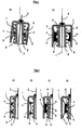
- FIG. 1 schematically shows a comparison between an existing one, as shown in part drawing a), and a fastening device or cap 1 according to the invention for a needle 2, as shown in part drawing b).
- the caps 1 each have a lower, open end and an upper, closed end, which holds the needle 2 centered and vertical.
- spring elements 3 are arranged in the manner of bending beam, in the middle of each a cam 4 is located. If the cap 1 is now slipped over a thread 5, the cams 4 engage in the thread 6 of the thread 5 in the existing solution a).
- the cams 4 are mounted analogously on spring elements 3, but have, in contrast to the existing cam 4, no easy, itself to the thread 5 towards tapered end. This has by a, extending horizontally to the lateral surface of the cap 1 notch 8 two tips 9, which each act perpendicular to the thread 6. The distance of the tips 9 of a cam 4 is at least as the height of the thread 6, resulting in at least three, not in the same plane contact points between the inventive fastening device or cap 1 and the thread 5. The needle 2 is thereby kept safe without tilting out of the solder or the axis of rotation 7 of the thread 5.
- FIG. 2 schematically shows a further advantage of the fastening device or cap 1 according to the invention with a notched cam 4, as shown in FIG the part drawing c) and d) is shown opposite a cap 1 with two conventional cams 4, as shown in the part drawing a) and b).
- These cams 4 act only perpendicular to a Thread 5 with the appropriate thread diameter, as shown in the drawing a). In the partial drawing b), the diameter of the thread 5 is smaller, whereby the spring element 3 bulges more in the direction of the thread 5.
- the cams 4 located thereon tilt according to the curvature of the spring element 3 from the vertical orientation on the thread. Consequently, the clamping force no longer acts optimally, that is, perpendicular to the thread 5, whereby the cap 1 less securely adhered to the thread 5.
- the inventive solution shown in part drawing c) and d) has an analog, acting in the manner of a bending beam spring element 3, on the center of a cam 4 is arranged.
- this cam 4 has a notch 8 and two directed to the thread 5 tips 9, whose distance is at least the height of the thread 6.
- the tips 9 and the spring force acts advantageous always perpendicular and with maximum spring force on the thread 5, even if the diameter of the thread 5 is smaller, as shown in the drawing d) with respect to the part drawing c).
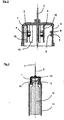
- FIG. 3 shows a horizontal section through a fastening device for injection needles 2 according to the invention, the cap 1 having segments of different thickness along the lateral surface.
- Slits 10 which do not extend all the way from the top to the bottom of the cap 1, separate the thinner segments on both sides from the thicker ones, allowing the thin segments to elastically deform analogously to a bending beam.
- the thus formed from the same material as the cap 1 spring elements 3 have in the middle a cam 4, which is a rigid, molded from the same material thickening with a horizontal notch 8 and two tips 9.
- FIG. 4 is a partial view of a schematic sectional view of an injection pen 11 with injection needle 2, which is securely attached or screwed onto the thread 5 with the aid of a fastening device or cap 1 according to the invention.
- a rotationally symmetrical ampoule 12 for example a filled with the drug, cylindrical reservoir of glass or plastic, is used in the designated part of the injection pen 11.
- the ampoule 12 has at one end a closure 13, which usually protrudes into the thread 5 of the injection pen 11.
- a part of the closure 13 is a septum 14 or a rubber membrane, which is pierced when plugging the cap 1 of the needle 2, if the one end of the needle 2 correspondingly far into the interior of the cap 1 protrudes.
- the drug is delivered from the ampule 12 into the needle 2 with a metering device, not shown.
- the needle 2 or cap 1 is removed, with the septum 14 closing again.
Landscapes
- Health & Medical Sciences (AREA)
- Vascular Medicine (AREA)
- Engineering & Computer Science (AREA)
- Anesthesiology (AREA)
- Biomedical Technology (AREA)
- Heart & Thoracic Surgery (AREA)
- Hematology (AREA)
- Life Sciences & Earth Sciences (AREA)
- Animal Behavior & Ethology (AREA)
- General Health & Medical Sciences (AREA)
- Public Health (AREA)
- Veterinary Medicine (AREA)
- Infusion, Injection, And Reservoir Apparatuses (AREA)
- Nitrogen Condensed Heterocyclic Rings (AREA)
Abstract
Description
- Die Erfindung bezieht sich auf Befestigungsvorrichtungen für Injektionsnadeln gemäss Oberbegriff des Patentanspruchs 1.
- In der ambulanten Medizin werden zur subkutanen Verabreichung von flüssigen Medikamenten zunehmend an Stelle von Einwegspritzen wiederverwendbare injektionsgeräte eingesetzt, zum Beispiel ein Injektionspen, welcher das Medikament in der gewünschten Menge mittels einer Dosiereinrichtung aus einer vorgefüllten Ampulle abgibt. Pro Injektion wird in der Regel jeweils auch eine neue Injektionsnadel, in der Folge einfach Nadel genannt, auf den Injektionspen aufgesetzt und nach deren Verwendung wieder entfernt. Die Nadel ist eine Hohlnadel zur Durchleitung von Arzneimittel von einem Vorratsbehälter in den Körper. Trotz gewisser Normen für Injektionsgeräte, bevorzugen die Hersteller Injektionsgeräte zu entwickeln, weiche spezifisch nur für ihre Medikamente geeignet sind. Somit hat praktisch jedes dieser Injektionsgeräte eine spezifische Befestigungsvorrichtung für die Nadel, welche dadurch nicht oder nur unsicher auf ein anderes Modell passt. Eine sichere Befestigung der Nadel auf einem Injektionspen ist dann, wenn diese weder rutscht noch aus dem Lot kippt Eine unsicher befestigte Nadel erhöht das Risiko von Verletzungen oder eines Nadelbruchs. Falls ein Arzt oder Patient mehrere Medikamente bzw. Injektionsgeräte für eine Therapie benötigt, ist er zudem auf eine entsprechende Vielfalt an Nadeln angewiesen, was deren Beschaffung und Lagerhaltung erschwert und bei kleineren Mengen auch teurer macht
- Folglich war man auf der Suche nach einer Befestigungsvorrichtung für Injektionsnadeln, weiche die Nadel auf unterschiedlichen Modellen von Injektionsgeräten sicher und lösbar befestigt, insbesondere auf den handelsüblichen Injektionspens mit einem Gewinde oder mit Gewindesegmenten zur lösbaren Befestigung der Nadel.
- Befestigungsvorrichtungen für Injektionsnadein zum Aufstecken oder Aufschrauben der Nadel auf das Gewinde oder Gewindesegment sind beispielsweise aus der Schrift
WO 95/01812 GB 737,676 - Um das Kippen zu verhindern, braucht es mindestens drei Kontaktpunkte zwischen der Innenseite der Kappe bzw. deren Nocken und dem Gewinde des Injektionspens, welche nicht In der gleichen Ebene sind und zudem die Kappe im Lot halten. Das heisst, dass diese Kontaktpunkte nach dem Aufstecken sich nicht mehr verschieben dürfen, ansonsten die Nadel entlang der Richtung der Nadel rutscht. Obschon nicht für Injektionspens vorgesehen, beschreiben die Patentschriften
US 2,894,509 undUS 2,828,743 Befestigungsvorrichtungen mit Nocken bzw. Nuten, weiche unabhängig von einer Gewindesteigung, nicht in der gleichen Ebene sind, und zwei feste Positionen und eine definierte Verschiebung einer Nadel ermöglichen. Die Lösung aus der SchriftUS 2,828,743 ist jedoch mit den praktisch den ganzen Umfang umschliessenden Nuten für das lösbare Aufstecken oder Aufschrauben auf ein Gewinde nicht geeignet. Die Lösung aus Figur 2 und 3 der SchriftUS 2,894,509 ist nur dann für ein Gewinde oder für Gewindesegmente geeignet, wenn die Nocken gleichmässig und rutschfest in die Gewindegänge eingreifen, was bei den unterschiedlichen Dimensionen der Gewinde selten der Fall ist. In besonderen Fällen kann auch diese Kappe aus dem Lot kippen, wobei das obere oder das untere Nockenpaar eine Kippachse beschreiben. Folglich wären mehr Nocken notwendig, um dieser Kippsymmetrie entgegen zu wirken. Mehr Nocken ergibt ferner den Vorteil, dass durch mehr Kontaktpunkte, die Klemmkraft in diesen Punkten kleiner sein darf, bei gleichbleibender Haftung der Kappe bzw. der Nadel auf dem Injektionspen. Die Klemmkraft entspricht einer Federkraft, weiche vorwiegend durch die Geometrie der Nocken, der Anordnung auf der Mantelfläche der Kappe und der Elastizität der Werkstoffe bestimmt wird. Eine kleinere Klemmkraft erlaubt daher bei gleichbleibender Federkraft einen grösseren Federweg der Nocken oder der Mantelfläche der Kappe. Folglich würde eine solche Kappe auf entsprechend grössere oder kleinere Gewindedurchmesser passen, vorausgesetzt die Klemmkraft wirkt stets gleich, vorzugsweise senkrecht auf das Gewinde des Injektionspens. Keine der bekannten Befestigungsvorrichtungen für Injektionsnadeln zeigt eine Lösung, bei der die Federkräfte in den Kontaktpunkten bei erhöhtem Federweg stets gleich, insbesondere senkrecht, auf das Gewinde wirken. Dies wäre der Fall, wenn die Nocken in der Mitte von federnden Elementen angebracht wären, welche mit je einem Ende, analog eines Dreipunkt-Biegeelements mit der formfesten Mantelfläche verbunden wären. Eine Verdoppelung der Kontaktpunkte, um einen grösseren Federweg der Nocken für ebenso grössere Unterschiede in den Durchmessern der Gewinde zu ermöglichen, erfordert mindestens doppelt so viel Platz auf der Innenseite der Mantelfläche von der Kappe. Dies ist bei den bekannten Lösungen mit bis zu maximal fünf Nocken konstruktiv sehr aufwändig oder gar nicht lösbar, bedenkt man, dass die Nocken auf unterschiedlichen Ebenen angeordnet sein müssen, falls die Kappe nicht aus dem Lot kippen soll. - Die Erfindung hat die Aufgabe, eine Befestigungsvordchtung für Injektionsnadeln mit mindestens 6 möglichen Kontaktpunkten auf mindestens zwei Ebenen zu schaffen, wobei die Federkräfte in den Kontaktpunkten vorzugsweise stets senkrecht auf das Gewinde des Injektionsgerätes wirken, damit die Nadel sicher auf mehrere Modelle von Injektionspens passt.
- Die erfindungsgemässe Befestigungsvorrichtung für Injektionsnadeln hat mindestens drei Nocken, deren sich zum Gewinde hin verjüngende Spitzen je mindestens eine parallel zum Mantelumfang angeordnete Kerbe aufweisen, womit jeder Nocken mindestens zwei ebenfalls senkrecht ins Gewinde eingreifende Spitzen hat. Diese Lösung ergibt mindestens drei, nicht in der gleichen Ebene liegende Klemmpunkte zwischen der Kappe und dem Gewinde, welche für einen festen Sitz der Kappe auf dem Gewinde erforderlich sind. Zudem reduzieren die zusätzlichen Klemmpunkte die benötigte Klemmkraft oder ermöglichen eine entsprechend höhere Elastizität der Nocken bzw. der Mantelfläche der Kappe, damit die Kappe bzw. die Nadel auf entsprechend grössere und kleinere Gewindedurchmesser passt.
- Bei einer bevorzugten Ausführung der erfindungsgemässen Befestigungsvorrichtung für Injektionsnadeln ist die Distanz zwischen den Spitzen eines jeden gekerbten Nockens mindestens die Höhe des grössten Gewindegangs, womit die Kappe ohne Rutschen oder Verkanten auf die entsprechenden Injektionspens mit unterschiedlicher Steigung und Form von Gewindegängen passt.
- Vorteilhaft für die erfindungsgemässe Befestigungsvorrichtung ist zudem, wenn die Mantelfläche der Kappe in der Höhe nicht elastisch verformbar ist, sondern daran Federelemente befestigt sind, welche die gekerbten Nocken halten. Vorzugsweise wirken diese Federelemente in der Art von Biegebalken, auf deren Mittelpunkte je ein gekerbter Nocken befestigt ist, womit dessen Spitzen stets optimal, das heisst senkrecht in die Gewindegänge eingreifen.
- Trotz der verbesserten Haftung der Injektionsnadel auf einem handelsüblichen Injektionsgerät, entspricht eine nach der Erfindung konstruierte Befestigungsvorrichtung dem üblichen Aufwand für die Konstruktion und Herstellung für Kappen, welche eine Injektionsnadel halten. Folglich lässt sich eine erfindungsgemasse Befestigungsvorrichtung für Injektionsnadeln ebenso kostengünstig und in grossen Serien als einstückiges Spritzgussteil aus Kunststoff herstellen. Durch seine gute Formbeständigkeit ist PCTG (Polycyclohexylen-dimethylen-therephtalat) für diese Anwendung ein besonders geeignetes Material.
- Eine besonders interessante Anwendung der erfindungsgemässen Befestigungsvorrichtung für Injektionsnadeln ist die ambulante Insulintherapie für Diabetiker, wobei die meisten Injektionspens je nach Therapie oft in diversen Kombinationen verwendet werden. Da diese Injektionspens als Medikamentenbehälter Ampullen haben, welche mit einem Septum bzw. einer Gummimembran verschlossen sind, muss das eine Ende der Nadel in die Kappe hineinragen, so dass diese beim Aufstecken der Kappe auf das Gewinde das Septum durchsticht. Bedingt durch ähnliche, das Septum haltende Verschlüsse der Ampullen, haben diese Injektionspens einen Aussendurchmesser des Gewindes oder Gewindesegments im Bereich von 9 bis 10mm. Gemäss der Erfindung passt eine Kappe mit einem entsprechend dimensionierten Innendurchmesser und mit mindestens fünf, regelmässig über den Umfang verteilten Federelementen und gekerbten Nocken sicher auf praktisch alle handelsüblichen Injektionspens für Insulin.
- Vorzugsweise handelt es sich bei der Nadel um eine 30 Gauge oder 31 Gauge Nadel. Besonders bevorzugt um eine Nadel kleiner als 31 Gauge.
- Bevorzugte Ausführungsbeisplele der erfindungsgemässen Befestigungsvorrichtung sind nachstehend mit Hilfe von Figuren beschrieben, wobei die Figuren folgendes darstellen:
- Fig. 1
- einen ersten schematisch dargestellten Vergleich zwischen einer bestehenden und einer erfindungsgemässen Befestigungsvorrichtung für Injektionsnadeln;
- Fig. 2
- einen zweiten schematisch dargestellten Vergleich zwischen einer bestehenden und einer erfindungsgemässen Befestigungsvorrichtung für Injektionsnadeln;
- Fig. 3
- einen Vertikalschnitt durch eine erfindungsgemässe Befestigungsvorrichtung für Injeklionsnadeln und
- Fig. 4
- eine Teilansicht einer schematischen Schnittzeichnung einer auf einem Injektionspen aufgesteckten Injektionsnadel mit einer erfindungsgemässen Befesdgungsvoffichtung.
- Die Figur 1 zeigt schematisch einen Vergleich zwischen einer bestehenden, wie in der Teilzeichnung a) dargestellt ist, und einer erfindungsgemassen Befestigungsvorrichtung bzw. Kappe 1 für eine Nadel 2, wie dies in der Teilzeichnung b) dargestellt ist. Die Kappen 1 haben je ein unteres, offenes Ende und ein oberes, geschlossenes Ende, welches die Nadel 2 mittig und senkrecht hält. An der inneren Mantelfläche der Kappen 1 sind Federelemente 3 in der Art von Biegebalken angeordnet, in deren Mitte sich je ein Nocken 4 befindet. Wird nun die Kappe 1 über ein Gewinde 5 gestülpt, so greifen in der bestehenden Lösung a) die Nocken 4 in den Gewindegang 6 des Gewindes 5. ist die Positionierung der Nocken 4 nicht der Steigung des Gewindegangs 6 angepasst, so kippt die Kappe 1 nachteilig aus dem Lot bzw. die Nadel 2 ist nicht mehr parallel zur Rotationsachse 7 des Gewindes 5. In der erfindungsgemässen Lösung b) sind die Nocken 4 analog auf Federelementen 3 angebracht, haben aber, im Gegensatz zu den bestehenden Nocken 4, kein einfaches, sich zum Gewinde 5 hin verjüngendes Ende. Dieses hat durch eine, horizontal zur Mantelfläche der Kappe 1 verlaufenden Kerbe 8 zwei Spitzen 9, welche je senkrecht in den Gewindegang 6 einwirken. Der Abstand der Spitzen 9 eines Nockens 4 ist mindestens als die Höhe des Gewindegangs 6, was mindestens drei, nicht in der gleichen Ebene liegende Kontaktpunkte zwischen der erfindungsgemässen Befestigungsvorrichtung bzw. Kappe 1 und dem Gewinde 5 ergibt. Die Nadel 2 wird dadurch sicher, ohne aus dem Lot bzw. der Rotationsachse 7 des Gewindes 5 zu kippen gehalten.
- In Figur 2 wird schematisch ein weiterer Vorteil der erfindungsgemässen Befestigungsvorrichtung bzw. Kappe 1 mit einem gekerbten Nocken 4, wie dies in der Teilzeichnung c) und d) dargestellt ist, gegenüber einer Kappe 1 mit zwei üblichen Nocken 4 gezeigt, wie dies in der Teilzeichnung a) und b) dargestellt ist. Das Federelement 3 in der unvorteilhaften Lösung a) und b), das in der Art eines Biegebalkens zwischen den beiden Enden der Kappe 4 angeordnet ist, hat zwei, mindestens die Höhe des Gewindegangs 6 beabstandete Nocken 4. Diese Nocken 4 wirken nur senkrecht auf ein Gewinde 5 bei entsprechendem Gewindedurchmesser, wie dies in der Teilzeichnung a) zu sehen ist. In der Teilzeichnung b) ist der Durchmesser des Gewindes 5 kleiner, wodurch sich das Federelement 3 mehr in Richtung des Gewindes 5 wölbt. Die sich darauf befindenden Nocken 4 kippen entsprechend der Wölbung des Federelements 3 aus der senkrechten Ausrichtung auf das Gewinde. Folglich wirkt die Klemmkraft nicht mehr optimal, das heisst, senkrecht auf das Gewinde 5, womit die Kappe 1 weniger sicher auf dem Gewinde 5 haftet. Die in der Teilzeichnung c) und d) gezeigte, erfindungsgemässe Lösung hat ein analoges, in der Art eines Biegebalken wirkendes Federelement 3, auf dessen Mitte ein Nocken 4 angeordnet ist. Gemäss der Erfindung hat dieser Nocken 4 eine Kerbe 8 und zwei zum Gewinde 5 gerichtete Spitzen 9, deren Abstand mindestens die Höhe des Gewindegangs 6 beträgt. Die Spitzen 9 bzw. die Federkraft wirkt vorteilhaft stets senkrecht und mit maximaler Federkraft auf das Gewinde 5 auch dann, wenn der Durchmesser des Gewindes 5 kleiner ist, wie dies in der Teilzeichnung d) gegenüber der Teilzeichnung c) gezeigt wird.
- Die Figur 3 zeigt einen Horizontaischnitt mittig durch eine Befestigungsvorrichtung für Injektionsnadeln 2 gemäss der Erfindung, wobei die Kappe 1 unterschiedlich dicke Segmente längs der Mantelfläche hat. Schlitze 10, die nicht ganz vom oberen zum unteren Ende der Kappe 1 reichen, trennen die dünneren Segmente beidseitig von den dickeren, wodurch sich die dünnen Segmente analog einem Biegebalken elastisch verformen können. Die so aus dem gleichen Material wie die Kappe 1 geformten Federelemente 3 weisen in der Mitte einen Nocken 4 auf, welcher eine steife, aus dem gleichen Material geformte Verdickung mit einer horizontalen Kerbe 8 und zwei Spitzen 9 ist.
- Die Figur 4 ist eine Teilansicht einer schematischen Schnittzeichnung eines Injektionspens 11 mit Injektionsnadel 2, welche mit Hilfe einer erfindungsgemässen Befestigungsvorrichtung bzw. Kappe 1 sicher auf das Gewinde 5 aufgesteckt oder aufgeschraubt ist. Eine rotationssymmetrische Ampulle 12, zum Beispiel ein mit dem Medikament befüllter, zylindrischer Vorratsbehälter aus Glas oder Kunststoff, wird in dem dafür vorgesehen Teil des Injektionspens 11 eingesetzt. Die Ampulle 12 hat am einen Ende einen Verschluss 13, welcher üblicherweise in das Gewinde 5 des Injektionspens 11 hineinragt. Ein Teil des Verschlusses 13 ist ein Septum 14 bzw. eine Gummimembran, welche beim Aufstecken der Kappe 1 von der Nadel 2 durchstochen wird, falls das eine Ende der Nadel 2 entsprechend weit in das Innere der Kappe 1 ragt. Anschliessend wird das Medikament mit einer Dosiereinrichtung, weiche nicht gezeigt ist, aus der Ampulle 12 in die Nadel 2 gefördert. Nach der Anwendung des Injektionspens 11 wird die Nadel 2 bzw. die Kappe 1 entfernt, wobei sich das Septum 14 wieder schliesst.
-
- 1
- Kappe
- 2
- Nadel
- 3
- Federelement
- 4
- Nocken
- 5
- Gewinde
- 6
- Gewindegang
- 7
- Rotationsachse
- 8
- Kerbe
- 9
- Spitze
- 10
- Schlitz
- 11
- Injektionspen
- 12
- Ampulle
- 13
- Verschluss
- 14
- Septum
Claims (10)
- Befestigungsvorrichtung für Injektionsnadeln zum Aufstecken auf ein Gewinde (5) eines Injektionsgerätes, wobei die Befestigungsvorrichtung als Kappe (1) mit einem offenen und einem geschlossenen, mittig senkrecht eine Nadel (2) haltenden, Ende geformt ist und eine Mantelfläche aufweist, dadurch gekennzeichnet, dass an oder in der Mantelfläche Federelemente angeordnet sind, wobei an einem Federelement eine gekerbte Nocke (4) angeordnet ist.
- Befestigungsvorrichtung für Injektionsnadeln nach Anspruch 1, dadurch gekennzeichnet, dass das Federelement an der Mantelfläche ein Biegebalken (3) ist.
- Befestigungsvorrichtung für Injektionsnadeln nach Anspruch 2, dadurch gekennzeichnet, dass der Biegebalken (3) im Bereich des oberen und unteren Endes der Kappe (1) mit dieser verbunden ist und auf dem Mittelpunkt des Biegebalkens eine gekerbte Nocke (4) befestigt ist, dessen Spitzen (9) stets senkrecht in die Gewindegänge (7) eingreifen.
- Befestigungsvorrichtung für Injektionsnadeln nach Anspruch 1, dadurch gekennzeichnet, dass die Mantelfläche der Kappe aus Längssegmenten mit unterschiedlich grossen Wandstärken besteht, und die Längssegmente durch Schlitze (10) getrennt sind, wobei ein Längssegment (3) mit einer kleineren Wandstärke das Federelement ist.
- Befestigungsvonichtung für Injektionsnadeln nach Anspruch 4, dadurch gekennzeichnet, dass die Längssegmente mit unterschiedlich grossen Wandstärken stoffgleich sind, die am oberen und unteren Ende mit der Kappe (1) stofflich verbunden sind und die mittig stoffgleiche, gekerbte und feste Nocken (4) aufweisen, deren Spitzen (9) senkrecht in die Gewindegänge (7) greifen.
- Befestigungsvorrichtung für Injektionsnadeln nach einen der vorhergehenden Ansprüche, dadurch gekennzeichnet, dass jede gekerbte Nocke (4) mindestens zwei senkrecht ins Gewinde (5) eingreifende Spitzen (9) hat.
- Befestigungsvorrichtung für Injektionsnadeln nach Anspruch 6, dadurch gekennzeichnet, dass die Spitzen (9) der gekerbten Nocken (4) mindestens drei, nicht in der gleichen Ebene liegende Kontaktpunkte ergeben.
- Befestigungsvorrichtung für Injektionsnadeln nach einem der vorhergehenden Ansprüche, dadurch gekennzeichnet, dass die Distanz zwischen den Spitzen (9) eines jeden gekerbten Nockens (4) mindestens gleich der Höhe des Gewindeganges (7) ist.
- Befestigungsvorrichtung für Injektionsnadeln nach einem der vorhergehenden Ansprüche, dadurch gekennzeichnet, dass die Befestigungsvorrichtung aus einem Teil gefertigt ist, vorzugsweise als Spritzgussteil.
- Befestigungsvorrichtung für Injektionsnadeln nach einem der vorhergehenden Ansprüche, dadurch gekennzeichnet, dass ein Ende der Nadel (2) in die Kappe (1) hineinragt, sodass diese beim Aufstecken der Kappe (1) auf das Gewinde (5) der Injektionseinheit in den mit Medikament befüllten Vorratsbehälter eindringt.
Applications Claiming Priority (2)
| Application Number | Priority Date | Filing Date | Title |
|---|---|---|---|
| CH01543/01A CH695288A5 (de) | 2001-08-21 | 2001-08-21 | Befestigungsvorrichtung fuer Injektionsnadeln. |
| EP02745035A EP1420840B1 (de) | 2001-08-21 | 2002-07-22 | Befestigungsvorrichtung für injektionsnadeln |
Related Parent Applications (1)
| Application Number | Title | Priority Date | Filing Date |
|---|---|---|---|
| EP02745035A Division EP1420840B1 (de) | 2001-08-21 | 2002-07-22 | Befestigungsvorrichtung für injektionsnadeln |
Publications (3)
| Publication Number | Publication Date |
|---|---|
| EP1759730A2 true EP1759730A2 (de) | 2007-03-07 |
| EP1759730A3 EP1759730A3 (de) | 2007-08-01 |
| EP1759730B1 EP1759730B1 (de) | 2016-03-09 |
Family
ID=4565546
Family Applications (2)
| Application Number | Title | Priority Date | Filing Date |
|---|---|---|---|
| EP06026254.0A Expired - Lifetime EP1759730B1 (de) | 2001-08-21 | 2002-07-22 | Befestigungsvorrichtung für Injektionsnadeln |
| EP02745035A Expired - Lifetime EP1420840B1 (de) | 2001-08-21 | 2002-07-22 | Befestigungsvorrichtung für injektionsnadeln |
Family Applications After (1)
| Application Number | Title | Priority Date | Filing Date |
|---|---|---|---|
| EP02745035A Expired - Lifetime EP1420840B1 (de) | 2001-08-21 | 2002-07-22 | Befestigungsvorrichtung für injektionsnadeln |
Country Status (8)
| Country | Link |
|---|---|
| US (2) | US8043249B2 (de) |
| EP (2) | EP1759730B1 (de) |
| JP (2) | JP4384490B2 (de) |
| CN (1) | CN1315546C (de) |
| AT (1) | ATE349237T1 (de) |
| CH (1) | CH695288A5 (de) |
| DE (1) | DE50209092D1 (de) |
| WO (1) | WO2003018092A1 (de) |
Families Citing this family (51)
| Publication number | Priority date | Publication date | Assignee | Title |
|---|---|---|---|---|
| CH695288A5 (de) * | 2001-08-21 | 2006-03-15 | Tecpharma Licensing Ag | Befestigungsvorrichtung fuer Injektionsnadeln. |
| US20080033347A1 (en) * | 2006-08-03 | 2008-02-07 | Becton, Dickinson And Company | Detachable needle syringe having reduced dead space |
| DE102006038123C5 (de) * | 2006-08-14 | 2012-05-03 | Tecpharma Licensing Ag | Injektionsvorrichtung mit Mechanikverriegelung |
| DE102007001432A1 (de) * | 2006-08-14 | 2008-02-21 | Tecpharma Licensing Ag | Dosiermechaniksperrung |
| DE102006038103B4 (de) * | 2006-08-14 | 2017-02-23 | Tecpharma Licensing Ag | Injektionsvorrichtung mit variabler Gewindeführung |
| CA2639322C (en) | 2007-09-07 | 2016-11-08 | Becton, Dickinson And Company | Pen needle hub having increased contact area |
| US10420880B2 (en) | 2007-10-02 | 2019-09-24 | West Pharma. Services IL, Ltd. | Key for securing components of a drug delivery system during assembly and/or transport and methods of using same |
| US9656019B2 (en) | 2007-10-02 | 2017-05-23 | Medimop Medical Projects Ltd. | Apparatuses for securing components of a drug delivery system during transport and methods of using same |
| US9173997B2 (en) | 2007-10-02 | 2015-11-03 | Medimop Medical Projects Ltd. | External drug pump |
| US9345836B2 (en) | 2007-10-02 | 2016-05-24 | Medimop Medical Projects Ltd. | Disengagement resistant telescoping assembly and unidirectional method of assembly for such |
| US7967795B1 (en) | 2010-01-19 | 2011-06-28 | Lamodel Ltd. | Cartridge interface assembly with driving plunger |
| US9393369B2 (en) | 2008-09-15 | 2016-07-19 | Medimop Medical Projects Ltd. | Stabilized pen injector |
| US12097357B2 (en) | 2008-09-15 | 2024-09-24 | West Pharma. Services IL, Ltd. | Stabilized pen injector |
| US10071198B2 (en) | 2012-11-02 | 2018-09-11 | West Pharma. Servicees IL, Ltd. | Adhesive structure for medical device |
| US10071196B2 (en) | 2012-05-15 | 2018-09-11 | West Pharma. Services IL, Ltd. | Method for selectively powering a battery-operated drug-delivery device and device therefor |
| US8157769B2 (en) | 2009-09-15 | 2012-04-17 | Medimop Medical Projects Ltd. | Cartridge insertion assembly for drug delivery system |
| US8348898B2 (en) | 2010-01-19 | 2013-01-08 | Medimop Medical Projects Ltd. | Automatic needle for drug pump |
| WO2011141907A1 (en) | 2010-05-10 | 2011-11-17 | Medimop Medical Projects Ltd. | Low volume accurate injector |
| USD702834S1 (en) | 2011-03-22 | 2014-04-15 | Medimop Medical Projects Ltd. | Cartridge for use in injection device |
| CN103100129B (zh) * | 2011-11-09 | 2015-09-02 | 温州市贝普科技有限公司 | 一种注射剂药液免转移的卡式瓶注射器 |
| EP2809375B1 (de) | 2012-01-31 | 2021-08-11 | Medimop Medical Projects Ltd. | Zeitabhängige wirkstofffreisetzungsvorrichtung |
| US9072827B2 (en) | 2012-03-26 | 2015-07-07 | Medimop Medical Projects Ltd. | Fail safe point protector for needle safety flap |
| US10668213B2 (en) | 2012-03-26 | 2020-06-02 | West Pharma. Services IL, Ltd. | Motion activated mechanisms for a drug delivery device |
| US9463280B2 (en) | 2012-03-26 | 2016-10-11 | Medimop Medical Projects Ltd. | Motion activated septum puncturing drug delivery device |
| US9421323B2 (en) | 2013-01-03 | 2016-08-23 | Medimop Medical Projects Ltd. | Door and doorstop for portable one use drug delivery apparatus |
| US9011164B2 (en) | 2013-04-30 | 2015-04-21 | Medimop Medical Projects Ltd. | Clip contact for easy installation of printed circuit board PCB |
| US9889256B2 (en) | 2013-05-03 | 2018-02-13 | Medimop Medical Projects Ltd. | Sensing a status of an infuser based on sensing motor control and power input |
| KR101473945B1 (ko) | 2013-09-13 | 2014-12-17 | 메디칸(주) | 주사기용 어댑터 세트 및 그를 포함한 주사기 |
| US9980521B2 (en) * | 2014-06-27 | 2018-05-29 | Philip Morris Products S.A. | Aerosol-generating system with improved piercing member |
| US10251813B2 (en) | 2015-03-04 | 2019-04-09 | West Pharma. Services IL, Ltd. | Flexibly mounted cartridge alignment collar for drug delivery device |
| US9795534B2 (en) | 2015-03-04 | 2017-10-24 | Medimop Medical Projects Ltd. | Compliant coupling assembly for cartridge coupling of a drug delivery device |
| US9744297B2 (en) | 2015-04-10 | 2017-08-29 | Medimop Medical Projects Ltd. | Needle cannula position as an input to operational control of an injection device |
| US10293120B2 (en) | 2015-04-10 | 2019-05-21 | West Pharma. Services IL, Ltd. | Redundant injection device status indication |
| KR20150001784U (ko) * | 2015-04-20 | 2015-05-08 | 박원귀 | 펜 타입 주사기 허브 및 제조방법 |
| US10149943B2 (en) | 2015-05-29 | 2018-12-11 | West Pharma. Services IL, Ltd. | Linear rotation stabilizer for a telescoping syringe stopper driverdriving assembly |
| EP3302652B1 (de) | 2015-06-04 | 2023-09-06 | Medimop Medical Projects Ltd. | Kartuscheneinführung für arzneimittelabgavevorrichtung |
| EP3106191B1 (de) * | 2015-06-15 | 2019-03-13 | Gerresheimer Regensburg GmbH | Sicherheitsvorrichtung für eine spritze |
| US10576207B2 (en) | 2015-10-09 | 2020-03-03 | West Pharma. Services IL, Ltd. | Angled syringe patch injector |
| US9987432B2 (en) | 2015-09-22 | 2018-06-05 | West Pharma. Services IL, Ltd. | Rotation resistant friction adapter for plunger driver of drug delivery device |
| JP7017512B2 (ja) | 2015-10-09 | 2022-02-08 | ウェスト ファーマ サービシーズ イスラエル リミテッド | 充填済流体容器の屈曲流体路型付属物 |
| JP6542481B2 (ja) | 2016-01-21 | 2019-07-10 | ウェスト ファーマ サービシーズ イスラエル リミテッド | システム |
| EP3711793B1 (de) | 2016-01-21 | 2021-12-01 | West Pharma Services IL, Ltd. | Verfahren zur verbindung einer patrone mit einem automatischen injektor |
| US11311674B2 (en) | 2016-01-21 | 2022-04-26 | West Pharma. Services IL, Ltd. | Medicament delivery device comprising a visual indicator |
| US11389597B2 (en) | 2016-03-16 | 2022-07-19 | West Pharma. Services IL, Ltd. | Staged telescopic screw assembly having different visual indicators |
| EP3463526B1 (de) | 2016-06-02 | 2024-08-21 | West Pharma. Services Il, Ltd. | Nadelrückzug mit drei positionen |
| EP3490643B1 (de) | 2016-08-01 | 2021-10-27 | West Pharma. Services Il, Ltd. | Verdrehsicherungsstift |
| EP3978047B1 (de) | 2016-08-01 | 2023-08-23 | West Pharma Services IL, Ltd | Feder zur verhinderung von teilweisem türverschluss |
| EP3630226B1 (de) | 2017-05-30 | 2025-10-22 | West Pharma. Services Il, Ltd. | Modularer antriebsstrang für am körper tragbaren injektor |
| CN114470420B (zh) | 2017-12-22 | 2024-08-27 | 西氏医药包装(以色列)有限公司 | 适用于不同尺寸的药筒的注射器 |
| CN113289154B (zh) * | 2021-06-28 | 2022-06-17 | 昆山爱希斯顿智能制造有限公司 | 一种注射美容用钝末端注射针 |
| US20240390587A1 (en) * | 2023-05-24 | 2024-11-28 | Claudio Esteban Ouwerkerk | Device for drug injection |
Family Cites Families (20)
| Publication number | Priority date | Publication date | Assignee | Title |
|---|---|---|---|---|
| US2894509A (en) * | 1952-01-18 | 1959-07-14 | Becton Dickinson Co | Hypodermic syringe |
| GB737676A (en) * | 1952-11-14 | 1955-09-28 | S & R J Everett & Co Ltd | Improvements relating to hypodermic needles |
| US2828743A (en) | 1957-06-17 | 1958-04-01 | American Home Prod | Snap-on cartridge-needle unit |
| US3344787A (en) * | 1964-08-13 | 1967-10-03 | Truelove & Maclean Inc | Hypodermic needle holders |
| US3857387A (en) * | 1972-12-26 | 1974-12-31 | Ultrasonic Systems | Ultrasonic cataract removal method and apparatus |
| AT360139B (de) * | 1978-10-16 | 1980-12-29 | Immuno Ag | Kombinierte ampullen-einweg-injektionsspritze |
| US4827911A (en) * | 1986-04-02 | 1989-05-09 | Cooper Lasersonics, Inc. | Method and apparatus for ultrasonic surgical fragmentation and removal of tissue |
| JPH021277A (ja) * | 1988-03-31 | 1990-01-05 | Fujisawa Pharmaceut Co Ltd | 輸液容器 |
| CA2001732A1 (en) * | 1988-10-31 | 1990-04-30 | Lawrence A. Lynn | Intravenous line coupling device |
| DE69019289T2 (de) * | 1989-10-27 | 1996-02-01 | Storz Instr Co | Verfahren zum Antreiben eines Ultraschallwandlers. |
| JPH06239352A (ja) * | 1993-02-05 | 1994-08-30 | Nissho Corp | 溶解液注入セット |
| CH685677A5 (de) * | 1993-07-09 | 1995-09-15 | Disetronic Ag | Befestigungsmechanismus für Nadelsysteme. |
| CN2235818Y (zh) * | 1995-01-24 | 1996-09-25 | 周华杰 | 可作试管用的一次性注射器 |
| US5984882A (en) * | 1996-08-19 | 1999-11-16 | Angiosonics Inc. | Methods for prevention and treatment of cancer and other proliferative diseases with ultrasonic energy |
| US5782803A (en) * | 1996-11-26 | 1998-07-21 | Jentzen; S. William | Low dead space, interchangeable needle syringe |
| US6558365B2 (en) * | 2001-01-03 | 2003-05-06 | Medimop Medical Projects, Ltd. | Fluid transfer device |
| US6656433B2 (en) | 2001-03-07 | 2003-12-02 | Churchill Medical Systems, Inc. | Vial access device for use with various size drug vials |
| EP1264609B1 (de) * | 2001-06-06 | 2006-01-18 | Graziano Azzolini | Hochsterilen sowie Hochkapazitativen Verbinder für Leitungen für ausfluss aus Flaschen |
| CH695288A5 (de) * | 2001-08-21 | 2006-03-15 | Tecpharma Licensing Ag | Befestigungsvorrichtung fuer Injektionsnadeln. |
| US6875205B2 (en) * | 2002-02-08 | 2005-04-05 | Alaris Medical Systems, Inc. | Vial adapter having a needle-free valve for use with vial closures of different sizes |
-
2001
- 2001-08-21 CH CH01543/01A patent/CH695288A5/de not_active IP Right Cessation
-
2002
- 2002-07-22 WO PCT/CH2002/000408 patent/WO2003018092A1/de not_active Ceased
- 2002-07-22 AT AT02745035T patent/ATE349237T1/de active
- 2002-07-22 EP EP06026254.0A patent/EP1759730B1/de not_active Expired - Lifetime
- 2002-07-22 JP JP2003522605A patent/JP4384490B2/ja not_active Expired - Lifetime
- 2002-07-22 DE DE50209092T patent/DE50209092D1/de not_active Expired - Lifetime
- 2002-07-22 CN CNB028162625A patent/CN1315546C/zh not_active Expired - Lifetime
- 2002-07-22 EP EP02745035A patent/EP1420840B1/de not_active Expired - Lifetime
-
2004
- 2004-02-19 US US10/782,735 patent/US8043249B2/en active Active
-
2006
- 2006-10-05 JP JP2006273698A patent/JP4614932B2/ja not_active Expired - Lifetime
-
2009
- 2009-06-05 US US12/479,753 patent/US8114046B2/en not_active Expired - Fee Related
Also Published As
| Publication number | Publication date |
|---|---|
| WO2003018092A1 (de) | 2003-03-06 |
| EP1420840A1 (de) | 2004-05-26 |
| CN1315546C (zh) | 2007-05-16 |
| JP4384490B2 (ja) | 2009-12-16 |
| ATE349237T1 (de) | 2007-01-15 |
| US20040186443A1 (en) | 2004-09-23 |
| DE50209092D1 (de) | 2007-02-08 |
| US8043249B2 (en) | 2011-10-25 |
| JP2007029750A (ja) | 2007-02-08 |
| CN1551787A (zh) | 2004-12-01 |
| JP4614932B2 (ja) | 2011-01-19 |
| JP2004538119A (ja) | 2004-12-24 |
| US8114046B2 (en) | 2012-02-14 |
| US20090240212A1 (en) | 2009-09-24 |
| EP1759730A3 (de) | 2007-08-01 |
| EP1759730B1 (de) | 2016-03-09 |
| EP1420840B1 (de) | 2006-12-27 |
| CH695288A5 (de) | 2006-03-15 |
Similar Documents
| Publication | Publication Date | Title |
|---|---|---|
| EP1420840B1 (de) | Befestigungsvorrichtung für injektionsnadeln | |
| DE60309479T2 (de) | Nadelbefestigungssystem zur befestigung einer nadelanordnung | |
| DE60202315T2 (de) | Flexible Nadelvorrichtung | |
| EP0022977B1 (de) | Vorrichtung für Injektionsspritzen | |
| DE69621515T2 (de) | Rückhaltevorrichtung für Spritzen zum Verhindern des unbeabsichtigten Herausziehens eines Kolbens | |
| EP0525525B1 (de) | Injektor | |
| DE69728357T2 (de) | Spritzenhalterung und eine die Halterung aufweisende Injektionsvorrichtung | |
| DE4200595C2 (de) | Baugruppe zum Infusion-Set für eine Insulinpumpe | |
| DE2939180C2 (de) | ||
| DE69405581T2 (de) | Injektionsspritzen | |
| DE29522418U1 (de) | Injektionsgerät | |
| WO1998011927A1 (de) | Abtriebsglied für den vorschub eines stopfens einer spritzampulle und stopfen hierzu | |
| DE29703820U1 (de) | Injektionsgerät | |
| DE10106367A1 (de) | Ablesehilfe für eine Vorrichtung zur Verabreichung einer einstellbaren Dosis eines injizierbaren Produkts | |
| DE102004004310A1 (de) | Injektionsgerät mit verrastbarem Dosierglied | |
| DE69001281T2 (de) | Wegwerfspritze fuer einmalverwendung. | |
| WO2002064199A1 (de) | Verstellsperre für eine vorrichtung zur verabreichung einer einstellbaren dosis eines injizierbaren produkts | |
| DE69016351T2 (de) | Sicherheitskappe für eine gebrauchte medizinische Nadel. | |
| DE69025320T2 (de) | Flasche mit Tropfvorrichtung | |
| EP1417981B1 (de) | Medizinische Spritze | |
| DE102006022081B3 (de) | Einstellvorrichtung für die Einstellung der Länge eines Injektionsabschnitts einer Injektionsnadel | |
| DE2800579C3 (de) | Einweg-Spritze | |
| CH397157A (de) | Injektionsspritze | |
| CH715313A2 (de) | Rückdrehsicherungsanordnung für Injektionsvorrichtung und Injektionsvorrichtung. | |
| DE3325046A1 (de) | Nadel fuer injektionsspritzen |
Legal Events
| Date | Code | Title | Description |
|---|---|---|---|
| PUAI | Public reference made under article 153(3) epc to a published international application that has entered the european phase |
Free format text: ORIGINAL CODE: 0009012 |
|
| AC | Divisional application: reference to earlier application |
Ref document number: 1420840 Country of ref document: EP Kind code of ref document: P |
|
| AK | Designated contracting states |
Kind code of ref document: A2 Designated state(s): AT BE BG CH CY CZ DE DK EE ES FI FR GB GR IE IT LI LU MC NL PT SE SK TR |
|
| PUAL | Search report despatched |
Free format text: ORIGINAL CODE: 0009013 |
|
| RIN1 | Information on inventor provided before grant (corrected) |
Inventor name: KIRCHHOFER, FRITZ Inventor name: SCHEIDEGGER, DANIEL Inventor name: LEHRMANN, HANS-ULRICH Inventor name: WENGER, STEFAN Inventor name: COVINO, GIAN-CARLO Inventor name: FIECHTER, PATRICK |
|
| AK | Designated contracting states |
Kind code of ref document: A3 Designated state(s): AT BE BG CH CY CZ DE DK EE ES FI FR GB GR IE IT LI LU MC NL PT SE SK TR |
|
| 17P | Request for examination filed |
Effective date: 20080201 |
|
| 17Q | First examination report despatched |
Effective date: 20080304 |
|
| AKX | Designation fees paid |
Designated state(s): AT BE BG CH CY CZ DE DK EE ES FI FR GB GR IE IT LI LU MC NL PT SE SK TR |
|
| GRAP | Despatch of communication of intention to grant a patent |
Free format text: ORIGINAL CODE: EPIDOSNIGR1 |
|
| INTG | Intention to grant announced |
Effective date: 20151016 |
|
| GRAS | Grant fee paid |
Free format text: ORIGINAL CODE: EPIDOSNIGR3 |
|
| GRAA | (expected) grant |
Free format text: ORIGINAL CODE: 0009210 |
|
| AC | Divisional application: reference to earlier application |
Ref document number: 1420840 Country of ref document: EP Kind code of ref document: P |
|
| AK | Designated contracting states |
Kind code of ref document: B1 Designated state(s): AT BE BG CH CY CZ DE DK EE ES FI FR GB GR IE IT LI LU MC NL PT SE SK TR |
|
| REG | Reference to a national code |
Ref country code: GB Ref legal event code: FG4D Free format text: NOT ENGLISH |
|
| REG | Reference to a national code |
Ref country code: DE Ref legal event code: R081 Ref document number: 50216134 Country of ref document: DE Owner name: YPSOMED AG, CH Free format text: FORMER OWNER: TECPHARMA LICENSING AG, BURGDORF, CH |
|
| REG | Reference to a national code |
Ref country code: AT Ref legal event code: REF Ref document number: 779033 Country of ref document: AT Kind code of ref document: T Effective date: 20160315 Ref country code: CH Ref legal event code: EP |
|
| REG | Reference to a national code |
Ref country code: IE Ref legal event code: FG4D Free format text: LANGUAGE OF EP DOCUMENT: GERMAN |
|
| REG | Reference to a national code |
Ref country code: DE Ref legal event code: R096 Ref document number: 50216134 Country of ref document: DE |
|
| REG | Reference to a national code |
Ref country code: NL Ref legal event code: MP Effective date: 20160309 |
|
| REG | Reference to a national code |
Ref country code: FR Ref legal event code: PLFP Year of fee payment: 15 |
|
| PG25 | Lapsed in a contracting state [announced via postgrant information from national office to epo] |
Ref country code: FI Free format text: LAPSE BECAUSE OF FAILURE TO SUBMIT A TRANSLATION OF THE DESCRIPTION OR TO PAY THE FEE WITHIN THE PRESCRIBED TIME-LIMIT Effective date: 20160309 Ref country code: ES Free format text: LAPSE BECAUSE OF FAILURE TO SUBMIT A TRANSLATION OF THE DESCRIPTION OR TO PAY THE FEE WITHIN THE PRESCRIBED TIME-LIMIT Effective date: 20160309 Ref country code: GR Free format text: LAPSE BECAUSE OF FAILURE TO SUBMIT A TRANSLATION OF THE DESCRIPTION OR TO PAY THE FEE WITHIN THE PRESCRIBED TIME-LIMIT Effective date: 20160610 |
|
| PG25 | Lapsed in a contracting state [announced via postgrant information from national office to epo] |
Ref country code: NL Free format text: LAPSE BECAUSE OF FAILURE TO SUBMIT A TRANSLATION OF THE DESCRIPTION OR TO PAY THE FEE WITHIN THE PRESCRIBED TIME-LIMIT Effective date: 20160309 Ref country code: SE Free format text: LAPSE BECAUSE OF FAILURE TO SUBMIT A TRANSLATION OF THE DESCRIPTION OR TO PAY THE FEE WITHIN THE PRESCRIBED TIME-LIMIT Effective date: 20160309 |
|
| PG25 | Lapsed in a contracting state [announced via postgrant information from national office to epo] |
Ref country code: EE Free format text: LAPSE BECAUSE OF FAILURE TO SUBMIT A TRANSLATION OF THE DESCRIPTION OR TO PAY THE FEE WITHIN THE PRESCRIBED TIME-LIMIT Effective date: 20160309 |
|
| PG25 | Lapsed in a contracting state [announced via postgrant information from national office to epo] |
Ref country code: SK Free format text: LAPSE BECAUSE OF FAILURE TO SUBMIT A TRANSLATION OF THE DESCRIPTION OR TO PAY THE FEE WITHIN THE PRESCRIBED TIME-LIMIT Effective date: 20160309 Ref country code: CZ Free format text: LAPSE BECAUSE OF FAILURE TO SUBMIT A TRANSLATION OF THE DESCRIPTION OR TO PAY THE FEE WITHIN THE PRESCRIBED TIME-LIMIT Effective date: 20160309 Ref country code: PT Free format text: LAPSE BECAUSE OF FAILURE TO SUBMIT A TRANSLATION OF THE DESCRIPTION OR TO PAY THE FEE WITHIN THE PRESCRIBED TIME-LIMIT Effective date: 20160711 |
|
| REG | Reference to a national code |
Ref country code: DE Ref legal event code: R097 Ref document number: 50216134 Country of ref document: DE |
|
| PG25 | Lapsed in a contracting state [announced via postgrant information from national office to epo] |
Ref country code: BE Free format text: LAPSE BECAUSE OF NON-PAYMENT OF DUE FEES Effective date: 20160731 |
|
| PLBE | No opposition filed within time limit |
Free format text: ORIGINAL CODE: 0009261 |
|
| STAA | Information on the status of an ep patent application or granted ep patent |
Free format text: STATUS: NO OPPOSITION FILED WITHIN TIME LIMIT |
|
| PG25 | Lapsed in a contracting state [announced via postgrant information from national office to epo] |
Ref country code: DK Free format text: LAPSE BECAUSE OF FAILURE TO SUBMIT A TRANSLATION OF THE DESCRIPTION OR TO PAY THE FEE WITHIN THE PRESCRIBED TIME-LIMIT Effective date: 20160309 |
|
| 26N | No opposition filed |
Effective date: 20161212 |
|
| PG25 | Lapsed in a contracting state [announced via postgrant information from national office to epo] |
Ref country code: BG Free format text: LAPSE BECAUSE OF FAILURE TO SUBMIT A TRANSLATION OF THE DESCRIPTION OR TO PAY THE FEE WITHIN THE PRESCRIBED TIME-LIMIT Effective date: 20160609 |
|
| PG25 | Lapsed in a contracting state [announced via postgrant information from national office to epo] |
Ref country code: MC Free format text: LAPSE BECAUSE OF FAILURE TO SUBMIT A TRANSLATION OF THE DESCRIPTION OR TO PAY THE FEE WITHIN THE PRESCRIBED TIME-LIMIT Effective date: 20160309 |
|
| REG | Reference to a national code |
Ref country code: IE Ref legal event code: MM4A |
|
| REG | Reference to a national code |
Ref country code: FR Ref legal event code: PLFP Year of fee payment: 16 |
|
| PG25 | Lapsed in a contracting state [announced via postgrant information from national office to epo] |
Ref country code: IE Free format text: LAPSE BECAUSE OF NON-PAYMENT OF DUE FEES Effective date: 20160722 |
|
| PG25 | Lapsed in a contracting state [announced via postgrant information from national office to epo] |
Ref country code: LU Free format text: LAPSE BECAUSE OF NON-PAYMENT OF DUE FEES Effective date: 20160722 |
|
| PG25 | Lapsed in a contracting state [announced via postgrant information from national office to epo] |
Ref country code: CY Free format text: LAPSE BECAUSE OF FAILURE TO SUBMIT A TRANSLATION OF THE DESCRIPTION OR TO PAY THE FEE WITHIN THE PRESCRIBED TIME-LIMIT Effective date: 20160309 |
|
| PG25 | Lapsed in a contracting state [announced via postgrant information from national office to epo] |
Ref country code: TR Free format text: LAPSE BECAUSE OF FAILURE TO SUBMIT A TRANSLATION OF THE DESCRIPTION OR TO PAY THE FEE WITHIN THE PRESCRIBED TIME-LIMIT Effective date: 20160309 |
|
| REG | Reference to a national code |
Ref country code: FR Ref legal event code: PLFP Year of fee payment: 17 |
|
| REG | Reference to a national code |
Ref country code: CH Ref legal event code: PUE Owner name: YPSOMED AG, CH Free format text: FORMER OWNER: TECPHARMA LICENSING AG, CH |
|
| REG | Reference to a national code |
Ref country code: DE Ref legal event code: R082 Ref document number: 50216134 Country of ref document: DE Representative=s name: SSM SANDMAIR PATENTANWAELTE RECHTSANWALT PARTN, DE Ref country code: DE Ref legal event code: R081 Ref document number: 50216134 Country of ref document: DE Owner name: YPSOMED AG, CH Free format text: FORMER OWNER: TECPHARMA LICENSING AG, BURGDORF, CH |
|
| REG | Reference to a national code |
Ref country code: AT Ref legal event code: PC Ref document number: 779033 Country of ref document: AT Kind code of ref document: T Owner name: YPSOMED AG, CH Effective date: 20201214 |
|
| REG | Reference to a national code |
Ref country code: GB Ref legal event code: 732E Free format text: REGISTERED BETWEEN 20210325 AND 20210331 |
|
| PGFP | Annual fee paid to national office [announced via postgrant information from national office to epo] |
Ref country code: AT Payment date: 20210720 Year of fee payment: 20 Ref country code: FR Payment date: 20210722 Year of fee payment: 20 Ref country code: IT Payment date: 20210730 Year of fee payment: 20 |
|
| PGFP | Annual fee paid to national office [announced via postgrant information from national office to epo] |
Ref country code: GB Payment date: 20210722 Year of fee payment: 20 Ref country code: DE Payment date: 20210721 Year of fee payment: 20 Ref country code: CH Payment date: 20210723 Year of fee payment: 20 |
|
| REG | Reference to a national code |
Ref country code: DE Ref legal event code: R071 Ref document number: 50216134 Country of ref document: DE |
|
| REG | Reference to a national code |
Ref country code: CH Ref legal event code: PL |
|
| REG | Reference to a national code |
Ref country code: GB Ref legal event code: PE20 Expiry date: 20220721 |
|
| REG | Reference to a national code |
Ref country code: AT Ref legal event code: MK07 Ref document number: 779033 Country of ref document: AT Kind code of ref document: T Effective date: 20220722 |
|
| PG25 | Lapsed in a contracting state [announced via postgrant information from national office to epo] |
Ref country code: GB Free format text: LAPSE BECAUSE OF EXPIRATION OF PROTECTION Effective date: 20220721 |