EP1759625B1 - A endoscope assembly with a disposable sheath - Google Patents
A endoscope assembly with a disposable sheath Download PDFInfo
- Publication number
- EP1759625B1 EP1759625B1 EP05781667A EP05781667A EP1759625B1 EP 1759625 B1 EP1759625 B1 EP 1759625B1 EP 05781667 A EP05781667 A EP 05781667A EP 05781667 A EP05781667 A EP 05781667A EP 1759625 B1 EP1759625 B1 EP 1759625B1
- Authority
- EP
- European Patent Office
- Prior art keywords
- channel
- endoscope
- disposal
- fluid
- sheath
- Prior art date
- Legal status (The legal status is an assumption and is not a legal conclusion. Google has not performed a legal analysis and makes no representation as to the accuracy of the status listed.)
- Expired - Lifetime
Links
Images



Classifications
-
- A—HUMAN NECESSITIES
- A61—MEDICAL OR VETERINARY SCIENCE; HYGIENE
- A61B—DIAGNOSIS; SURGERY; IDENTIFICATION
- A61B1/00—Instruments for performing medical examinations of the interior of cavities or tubes of the body by visual or photographical inspection, e.g. endoscopes; Illuminating arrangements therefor
- A61B1/00064—Constructional details of the endoscope body
- A61B1/00071—Insertion part of the endoscope body
- A61B1/0008—Insertion part of the endoscope body characterised by distal tip features
- A61B1/00091—Nozzles
-
- A—HUMAN NECESSITIES
- A61—MEDICAL OR VETERINARY SCIENCE; HYGIENE
- A61B—DIAGNOSIS; SURGERY; IDENTIFICATION
- A61B1/00—Instruments for performing medical examinations of the interior of cavities or tubes of the body by visual or photographical inspection, e.g. endoscopes; Illuminating arrangements therefor
- A61B1/00064—Constructional details of the endoscope body
- A61B1/00071—Insertion part of the endoscope body
- A61B1/0008—Insertion part of the endoscope body characterised by distal tip features
- A61B1/00101—Insertion part of the endoscope body characterised by distal tip features the distal tip features being detachable
-
- A—HUMAN NECESSITIES
- A61—MEDICAL OR VETERINARY SCIENCE; HYGIENE
- A61B—DIAGNOSIS; SURGERY; IDENTIFICATION
- A61B1/00—Instruments for performing medical examinations of the interior of cavities or tubes of the body by visual or photographical inspection, e.g. endoscopes; Illuminating arrangements therefor
- A61B1/00131—Accessories for endoscopes
- A61B1/00135—Oversleeves mounted on the endoscope prior to insertion
-
- A—HUMAN NECESSITIES
- A61—MEDICAL OR VETERINARY SCIENCE; HYGIENE
- A61B—DIAGNOSIS; SURGERY; IDENTIFICATION
- A61B1/00—Instruments for performing medical examinations of the interior of cavities or tubes of the body by visual or photographical inspection, e.g. endoscopes; Illuminating arrangements therefor
- A61B1/00131—Accessories for endoscopes
- A61B1/00137—End pieces at either end of the endoscope, e.g. caps, seals or forceps plugs
-
- A—HUMAN NECESSITIES
- A61—MEDICAL OR VETERINARY SCIENCE; HYGIENE
- A61B—DIAGNOSIS; SURGERY; IDENTIFICATION
- A61B1/00—Instruments for performing medical examinations of the interior of cavities or tubes of the body by visual or photographical inspection, e.g. endoscopes; Illuminating arrangements therefor
- A61B1/00131—Accessories for endoscopes
- A61B1/0014—Fastening element for attaching accessories to the outside of an endoscope, e.g. clips, clamps or bands
-
- A—HUMAN NECESSITIES
- A61—MEDICAL OR VETERINARY SCIENCE; HYGIENE
- A61B—DIAGNOSIS; SURGERY; IDENTIFICATION
- A61B1/00—Instruments for performing medical examinations of the interior of cavities or tubes of the body by visual or photographical inspection, e.g. endoscopes; Illuminating arrangements therefor
- A61B1/00142—Instruments for performing medical examinations of the interior of cavities or tubes of the body by visual or photographical inspection, e.g. endoscopes; Illuminating arrangements therefor with means for preventing contamination, e.g. by using a sanitary sheath
-
- A—HUMAN NECESSITIES
- A61—MEDICAL OR VETERINARY SCIENCE; HYGIENE
- A61B—DIAGNOSIS; SURGERY; IDENTIFICATION
- A61B1/00—Instruments for performing medical examinations of the interior of cavities or tubes of the body by visual or photographical inspection, e.g. endoscopes; Illuminating arrangements therefor
- A61B1/012—Instruments for performing medical examinations of the interior of cavities or tubes of the body by visual or photographical inspection, e.g. endoscopes; Illuminating arrangements therefor characterised by internal passages or accessories therefor
- A61B1/018—Instruments for performing medical examinations of the interior of cavities or tubes of the body by visual or photographical inspection, e.g. endoscopes; Illuminating arrangements therefor characterised by internal passages or accessories therefor for receiving instruments
-
- A—HUMAN NECESSITIES
- A61—MEDICAL OR VETERINARY SCIENCE; HYGIENE
- A61B—DIAGNOSIS; SURGERY; IDENTIFICATION
- A61B1/00—Instruments for performing medical examinations of the interior of cavities or tubes of the body by visual or photographical inspection, e.g. endoscopes; Illuminating arrangements therefor
- A61B1/00064—Constructional details of the endoscope body
- A61B1/00071—Insertion part of the endoscope body
- A61B1/0008—Insertion part of the endoscope body characterised by distal tip features
- A61B1/00089—Hoods
Definitions
- This invention relates to endoscope and more particularly to an endoscope system with a disposal sheath for effective isolation of an endoscope from contamination on endoscopy, it is an improvement on traditional medical endoscopes to solve disposal sterilization, belongs to medical instrument field, suited for clinical use in hospitals.
- Medical endoscope is used for diagnostic and therapeutic purpose during Micro-invasive surgery due to its incomparable function, because the morpho-characters and excision of focus can be directly observed and performed on endoscopy. But the serious problem is medical cross-infection in particular some virus infection, such as Hepatitis and AIDS, via blood or other body fluid by endoscopy. Therefore, disposable small medical instruments should be recommended.
- endoscopes as an interfering instrument are quite high cost at present. People have not found any excellent way to effect and conveniently sterilize and prevent endoscopes from damage simultaneously. By now autoclaved method is recommended for some rigid, endoscopes' sterilization due to application of some optical glues which could bear high temperature and high pressure.
- the US patent numbered 5050585 (forming the preamble of claim 1) provides that of the disposal channel settled in inside of traditional endoscopes, and the anterior opening of disposal channel connected with the disposal sheath which covers on the endoscope to protect endoscope's outer surface and inner surface of opened channel, that is a good idea.
- Japanese Pentax company on this basis applied lots of patents for improvement later on.
- the cross-infection problem of medical endoscope in clinic application has yet not solved. In order to produce this kind of product, it will have yet a quite long way to go. More details are also needed to improve, such as fluid-air channel's position in endoscope system and other located connecting structure and correctly treat the disposal channel after use etc. All of such problems must be solved by new way.
- This invention provides a safe matching assembly system with an endoscope disposal sheath, to solve medical cross-infection thoroughly. That is to put forward newly program, improve lots of details, and reach clinical practice.
- the invention is defined in claim 1.
- the innovative uses a disposal sheath to ensure the endoscope not contaminant in clinic application.
- the said disposal sheath consists of a end cap, a capsule, a disposal channel, a soft double cavity fluid-air channel, a jet channel, a locking ring.
- Said end cap connects the disposal capsule which located in outside endoscope and the disposal channel which located in the endoscope channel and the soft double cavity fluid-air channel, thus all together connect with and join in a whole body, then to protect the endoscope's outer surface and channel's inner surface as well.
- the end cap is made from some elastic or partial elastic transparent materials, its inner end face's size fits in the end face's size of anterior endoscope.
- the end cap's inner face matches the endoscope body.
- a jet channel orifice is coaxially set at the anterior end cap to fix the jet channel.
- the space between the ditch and the channel need to tight glue with certain adhesive.
- a fixing seat or a fixing orifice of the disposal channel is set at the endoscope's operation orifice's position in the end surface of the end cap for convenient connecting with the disposal channel.
- the outer surrounding of posterior end cap is sheathed in the anterior end of the capsule.
- the capsule is made from elastic flexible thin wall nonpoisonous, non-immune biocompatible and lubricant or lubricated, medical material.
- the capsule covers the outside of endoscope.
- the posterior capsule connects a locking ring.
- the elastic capsule While pull to lengthen, the elastic capsule can be locked by the locking ring to ensure the anterior inner face of the end cap constantly and tight close to anterior end face of the endoscope. Since no space between the capsule end cap end anterior tip of the endoscope, reflected complicated light formed by lighting ray at observation system can be decreased.
- the upper and lower handles of the locking ring have corresponding oblique teeth to tighten or loose the posterior capsule.
- the fluid-air channel is connected to posterior end of the jet channel, and located in between the endoscope and the capsule, the fluid-air channel can be a single cavity or double cavities, or the structure of two single cavity channels together join in one cavity channel at nearing jet channel site, its channel's size can be cylinder, or flat orifice, said the structure of single cavity channels, may be two flat channels which is formed via heat pressure, and parallel together with each other thin wall channels.
- the flat channels is not easy to be bent and to block the flowing fluid-air also can be inflated and expanded into two cylinder channel cavities while flowing fluid-air flow into them, said the structure of double cavity fluid-air channel, Inside of the anterior part of it which sheathes on the jet channel has not any septum, but inside the later part of the double cavity channel has a septum, and at the back of the jet channel anterior septum has a round head which fits in the inner wall of the channel cavity, and there is a section of incision, respectively at situation of the septum's two sides, separated from the channel wall in order to make the septum swing towards any side of channel cavity to block the channel which the flowing fluid needs not flow into;
- the posterior soft double cavity channel(including two channels) is sheathed on two rigid connecting tubes that is has two parallel channels which are welded together, the posterior orifice of two rigid connecting tube are sheathed in two adapters of the two soft channels connecting with fluid and air channels respectively.
- the jet of the jet channel which is connected with the anterior double cavity channel, sprays out the fluid or air and direct towards the outer surface of the end cap and fits in the object lens situated inside of the end cap.
- the disposal channel is made of flexible, durable, hard to bent, bear negative pressure and electric arc-resistant medical materials, its anterior tip connects with the end cap. Its connecting method includes to directly sheathe and glue the disposal channel on the end cap by set a channel seat or to sheathe by a channel seat which can bear high temperature and be electric arc-resistant, glued in fixing orifice of the end cap.
- the endoscope body needs to be improved as follows:
- this invention also may use a kind of three-way sealing cap, a guide tube, a sucking tube and two kinds of heat fusion forceps which can shear disposal channel to V-shape cut edge. This can isolate the endoscope channel from the contaminated disposal channel.
- the three-way sealing cap is made from elastic material, the straight cavity is used for fixing and sealing the posterior end of the disposal channel and used as entrance or exit of instrument, its anterior end can be fixed on the exit of the endoscope channel, and on one side of the straight cavity set a sucking channel adapter used as a sucking way connecting the sucking tube via the disposal channel.
- Three elastic sealing orifices are set in the straight cavity.
- the inner diameter of three elastic sealing orifices is less than the outer diameter of the disposal channel.
- the invention provides a kind of guide tube.
- the inner diameter of the guide tube is more than the outer diameter of the disposal channel.
- the outer diameter of the guide tube is more than the inner diameter of three sealing orifices of the three-way sealing cap.
- the guide tube Due to the guide tube is made of rigid thin wall of tube, it can be, in advance, inserted into three-way sealing cap as to put the disposal channel into it with convenience. After the three-way sealing cap was fixed on, the guide tube is pulled out, then the disposal channel is kept in the three-way sealing cap. In order to let the disposal channel is correctly put in the exit of the second elastic sealing orifice, a tube core is set in the guide tube and the over-length part which is heightened than the sucking channel orifice can be pushed to the above mentioned application position by the lower end of the tube core. The inserting deepness of the guide tube core depends on the distance between the handle limiting face and orientation pin.
- the orientation pin is pushed to in front of the third elastic sealing orifice by the posterior end of the guide tube's long orifice, and to be blocked, during the process of pulling the guide tube out although the lower end of the guide tube leave away from the first elastic sealing orifice, the disposal channel, instantly is held by the first elastic sealing orifice, cannot turn over to raise till the guide tube bring the tube core continuous pulled out so that the disposal channel again be blocked in the second elastic sealing orifice of the three-way sealing cap and be then sealed and be keep-held, till the guide tube is pulled out wholly.
- the disposal sheath and the endoscope While the disposal sheath and the endoscope being in use, the first thing is to insert the disposal channel into the endoscope channel, later the other part of the disposal sheath is sheathed into it respectively.
- an endoscope instrument such as biopsy forceps into the endoscope channel
- the disposal channel can be smoothly passed into the endoscope channel along a space between the endoscope instrument and endoscope channel. Then outside of endoscope can also be covered on by another part of the disposal sheath.
- the capsule's elastic thin membrane makes the end cap's inner end and anterior endoscope end's surface tight close with each other. There is clear vision field so far.
- the anterior end orifice of the guide tube which was inserted in the anterior three-way sealing cap sheathes on outside of posterior end orifice of the disposal channel, sheathes forwards and the three-way sealing cap is fixed on the endoscope channel exit site and the sucking channel connecting with the three-way sealing cap is connected to the sucking channel adapter, it can be used in clinic application after pulling out the guide tube when finishing this process , and two channels (fluid channel and air channel) are connected to two exit (fluid exit and air exit) of the endoscope respectively.
- the three-way sealing cap and the sucking channel need to pull out(the three-way sealing cap and the sucking channel are made of high temperature resistant material so that they can be reused after cleaning and disinfecting, of course also can be disposal), then the disposal sheath need to pull out Due to the disposal channel orifice has been contaminative, the outlet of the disposal channel must be well blocked. After be blocked and then extracted, this can avoid the endoscope channel from pollution.
- the endoscope channel can be protected and prevented from becoming re-polluted source in the later use. Two kinds of heat fusion forceps for cutting the outlet of the disposal channel and fusing certain shape of the disposal channel at the position nearing the posterior outlet of the disposal channel may be used.
- the cut edge's size also need to meet certain requirement, that is while the sheared outlet of the disposal channel passed the endoscope channel, the cut-edge's shape becomes a V-shape, the disposal channel's shape still all is a full cylindrical not to be squeezed and opened, the cut edge's shape needs to become a V-shape.
- This invention may provide two kinds of V-shape cut edge which can satisfy the goal.
- Structure of the one of the heat fusion forceps is to set a piece of electric resistance thread in axial direction with V-shape at the forceps exit plane (the V-shape electric resistance thread also can be installed in contradirectional position), to set a flexible insulation board at an opposite plane's piece which can freely swing.
- the two planes are parallel with each other and can be freely closed.
- the second kind of heat fusion forceps has two pieces structures, piece-upper and piece-lower with a same degree, formed positive and negative V-shapes forceps exit. One piece can be moved radially and swing relatively for parallel pressurization to the channel exit. After heat the electric thread, the sheared outlet of the disposal channel can be changed into V-shape in radial direction as the first kind of heat fusion forceps also can achieve the same effectiveness. Compare to present technology, this invention has following advantages:
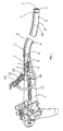
- This invention consists of two parts, an improved permanent endoscope and a disposal sheath, altogether formed an endoscope system with the disposal sheath (see Fig.1 ). It offers the permanent endoscope, which can be used for many times, to be protected by the disposal sheath from pollution.
- the disposal sheath (see fig.2 ) not only has the capsule 8 and the end cap 2, to protect the endoscope louter-surface, but also has a disposal channel 3 placed into the endoscope channel 10 to protect the endoscope channel's inner-surface.
- the capsule and the disposal channel are connected through the end cap 2. And they are joined in a whole body, therefore, the endoscope of both inside and outside are protected in all.
- the anterior endoscope 1 there is not any fluid-air channel or jet channel.
- the fluid-air channel and the jet channel are removed to the outside of the endoscope position between the endoscope 1 and the capsule 8.
- the jet channel is fixed in the jet channel ditch which located in one side of the end cap, the fluid-air exit 7 and the sucking channel adapter 16 are set on the posterior endoscope.
- the fluid-air exit 7 and the sucking channel adapter 16 connect the fluid-air channel adapter 6 and the sucking channel 17 respectively.
- the sucking channel adapter 12.5 of the three-way sealing cap 12 sheathed with another end of the sucking channel 17.
- the disposal sheath consists of the end cap2, the capsule 8, the disposal channel 3, the locking ring 9, the fluid-air channel 4, the jet channel 5, the fluid-air channel adapter 6, the three-way sealing cap12, the sucking channel 17 and guide tube 13 etc.
- the invention preferably also provides the traction forceps and two kinds of heat fusion forceps 14 and 15 for simultaneous melting and cutting the disposal channel 3 after the use, the end cap 2 is made of transparent or partial flexible transparent material.
- this invention preferably provides two kinds of program: due to conventional endoscopes' anterior end surface are not flat, and have different size, the invention offers the end cap as shown in figure 8 .
- the end surface of the end cap is made of elastic, flexible, thin membrane, so that it can close to the illumination out-going light and the observation system while it is pulled and tightened and the complication light reflected between them can be decreased.
- the invention preferably provides special endoscope-its anterior end surface is quite flat.
- a kind of end cap, improved by this invention processes its flat anterior inner surface. This makes closely contact possible between anterior end surface of endoscope and inner end surface of the end cap 2 which can decrease complication light as well.
- the posterior end of the jet channel 5 is connected with the fluid-air channel.
- the jet orifice of the jet channel 5 directs towards, outer end surface of the end cap relative to the object lens' position, and buckle up in the through ditch 2.3, its posterior end sheathes the fluid-air channel 4 the exit of the jet channel 5 directs towards the outer surface of the end cap relative to the object lens site.
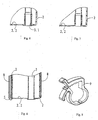
- Anterior end cap similar with anterior end of the endoscope, at the position of endoscope channel, opening the end surface of end cap 2 connects with the disposal channel 3, there are three connection ways:1) as shown in Fig 6 , adopting the channel seat 3.1 to connect the end cap 2 with adhesive; 2) as shown in Fig 7 , the channel seat 3.1 and the end cap 2 formed a whole body; 3) as shown in Fig 8 , without any channel seat, the tip of the disposal channel turned over outwards.
- the capsule tight covers the outside of end cap 2.
- the parts that the end cap 2 connected with including the capsule 8, the jet channel 5, the disposal channel seat 3.1, the disposal channel 3, all applied with medical adhesive.
- the capsule 8 is made of lacto rubber thin membrane material, or PVC thin membrane tube or polyaminoesters, or other high molecular material etc. Anterior end of the capsule 8 adhesively connects with the outside of posterior end cap 2 or majority of the outside of end cap 2.
- the length and diameter of the capsule 8 matches the length and diameter of the endoscope body, its posterior end connects to the locking ring 9. All of those connections are adhered with adhesive.
- the disposal channel 3 is made from sturdy, elastic, high temperature resistance, electric arc resistance and bear negative pressure material, its length and diameter matches the length and diameter of the endoscope channel. Its anterior end is adhered on the end surface of the end cap 2, sites in the endoscope channel.
- the operation can be: firstly to insert an instrument such as biopsy forceps into the endoscope channel 10, let the instrument's head surpass anterior end of endoscope channel, then outside of the instrument sheathes in the disposal channel, they are inserted into the endoscope channel 10 altogether. As shown in Fig.19 and Fig 20 , a traction forceps can be used, if necessary, to pull the disposal channel 3 passing through the endoscope channel 10.
- the traction forceps has two pieces of forceps piece, one piece is a cylinder and other piece is a half bullet size for contacting most area of channel wall.
- the lock of the forceps handle has some locking teeth While the disposal channel 3 passes through the endoscope channel, the capsule 8 and the end cap 2 are pulled by the locking ring 9 and heightened.
- Two fluid-air channels adapters 6 sheathe on the fluid-air exit 7 of the endoscope.
- the fluid-air channel can be single cavity or double cavity channel or the structure of two single cavity channels are joined together in one channel at nearing jet channel site , the channels shape may be cylinders, or flat shape as shown in fig.5 the fluid-air channel consisted of two single cavity channels may be consisted of two flat channels, which is formed via heat pressure, and parallel together with each other.
- the advantage of the flat channel is can not bent and can not be blocked by the flowing fluid-air, in addition, the closing channel which is not entered into by the flowing fluid-air only occupies less space, as shown in fig 3, 4 ) said of the structure of two fluid-air channel 4, it has not any septum inside the sheathed part with the jet channel 5.
- septum cavity 4.1 inside the later part of the double cavity channel has a septum cavity 4.1 and on the anterior septum part of the double cavity channel at the back of the jet channel swinging set a septum of round head 4.2, its curve rate of double cavity septum head R2 fits the curve rate of the channel cavity.
- the septum section of round head 4.2 can be swung towards the left or right, to block the one of two cavities of the channel which flowing fluid needs not to flow into, prevent injecting fluid or air from back flowing into this one cavity.
- a connecting material in this application example is a welding pad piece
- the part of the posterior end of disposal channel 3, which passed through the posterior end of the endoscope 11, needs to sheathe in a three-way sealing cap 12 as shown in Fig. 10 .
- the straight cavity of the three-way sealing cap 12 has upper adapter 12.6and lower adapter 12.4.
- the first elastic sealing orifices 12.1, the second elastic sealing orifices 12.2, and the third elastic sealing orifices 12.3 are also set inside the straight cavity of the three-way sealing cap 12.
- the sucking channel adapter 12.5 is set for sheathing the sucking channel 17.
- the sucking channel 21 connects with sucking channel adapter 16.
- the sucking channel adapter20 connects with some relative channel or handy valve inside the endoscope. To suck the anterior disposal channel's fluid into fluid reserve by handy valve when needed.
- the guide tube 13 consists of a tube body 13.8 with a handle 13.2, a guide tube core 13.1, a long orifice 13.4, a orientation pin 13.3.
- the tube body 13.8 is made of thin wall tube. A certain length, symmetrical long orifice 13.4 is set at surface of its one side, to let the orientation pin 13.3 across the tube core 17.1 conveniently and slide in it.
- the distance between the handle end face 13.6 and posterior end of long orifice equals to the distance between the upper orifice of the three-way sealing cap and lower end face of the third elastic sealing orifice.
- the long orifice's length is more than the distance between the lower end of the guide tube and the first elastic sealing orifice of the three-way sealing cap.
- the three-way sealing cap12 is prepared to sheathe in the disposal channel 3 and fix on endoscope channel exit, the followings are needed to be done: firstly to let the guide tube 13(as shown in Fig.12 ) sheathe in the three-way sealing cap 12, then to aim the lower end orifice 13.5 of the guide tube 13 at and cover the disposal channel orifice. While the three-way sealing cap 12 and sheathes on the endoscope (as shown in Fig.13 ) over length posterior end of disposal channel 3 is pressured to lower end of the sucking orifice by lower end of tube core 13.7. The orientation of the lower end of tube core 13.7 depends on the deepness decided by the orientation pin 13.3 and handle end face 13.6.
- the disposal channel After clinic use, the disposal channel has contaminated all around, must be taken off treated as medical rubbish. Before the disposal channel 3 is taken out from the endoscope channel 10, the posterior end of channel orifice must be blocked, otherwise the endoscope channel 10 will be polluted.
- the blocking method is to ensure sterilizing the channel orifice and not reopen the channel orifice because of its bad size during the taking out process. Therefore, this invention may use two kinds of heat fusion forceps 14 and 15 (respectively as shown in Fig 15 and Fig 17 ).
- the disposal channel's orifice can be cut off and formed a V-shape by heating the electric resistance thread to one piece of two pieces of forceps exit. The cut-edge's temperature reaches sterilization condition.
- Said two forceps concrete structures are as follows: one is, as shown in Fig.15 , the kind of heat fusion forceps 14, its channel orifice forms V-shape in radial direction V-shape electric resistance thread 14.2 in radial direction is parallel set on one piece of forceps opening. A cut edge by the heat fusion forceps of the disposal channel 3 formed a radial V-shape section as shown in Fig.16 . The action of the forceps piece 14.3 makes the channel orifice balance and symmetric heating fusion; another heat fusion forceps 19 structured an axial direction V-shape of cut edge as shown in Fig.17 .
- a movable insulation active board 15.1, set on one forceps piece, can form symmetric heat fusion. Its cutting edge forms a V-shape as shown in Fig.18 .
- the disposal channel 3 can basically be full cylindrical shape of channel for ensure after cutting off by this method, therefore, can be securely taken off from the endoscope channel 11 in favor of the blocked channel orifice not reopening.
- the disposal channel 3 formed an axial direction V-shape cut edge of channel-other V-shape channel 3.3 after cutting off by the heat fusion forceps ( Fig.17 ). As shown in Fig.
- the electric resistance thread 14.2 of the forceps orifice can be set and swung contradirectionally the same effeteness to the formed V-shape cut edge 3.2.
- Due to the three-way sealing cap 12 and the sucking channel 17 are made of materials which can bear high temperature, so that they can be reused after cleaning and disinfecting, of course also can be disposal. Since the sucking channel 13 did not contact with contamination at all, it can be cleaned by common method.
Landscapes
- Health & Medical Sciences (AREA)
- Life Sciences & Earth Sciences (AREA)
- Surgery (AREA)
- Biomedical Technology (AREA)
- Medical Informatics (AREA)
- Optics & Photonics (AREA)
- Pathology (AREA)
- Radiology & Medical Imaging (AREA)
- Biophysics (AREA)
- Engineering & Computer Science (AREA)
- Physics & Mathematics (AREA)
- Heart & Thoracic Surgery (AREA)
- Nuclear Medicine, Radiotherapy & Molecular Imaging (AREA)
- Molecular Biology (AREA)
- Animal Behavior & Ethology (AREA)
- General Health & Medical Sciences (AREA)
- Public Health (AREA)
- Veterinary Medicine (AREA)
- Endoscopes (AREA)
- Surgical Instruments (AREA)
- Orthopedics, Nursing, And Contraception (AREA)
Abstract
Description
- This invention relates to endoscope and more particularly to an endoscope system with a disposal sheath for effective isolation of an endoscope from contamination on endoscopy, it is an improvement on traditional medical endoscopes to solve disposal sterilization, belongs to medical instrument field, suited for clinical use in hospitals.
- Medical endoscope is used for diagnostic and therapeutic purpose during Micro-invasive surgery due to its incomparable function, because the morpho-characters and excision of focus can be directly observed and performed on endoscopy. But the terrible problem is medical cross-infection in particular some virus infection, such as Hepatitis and AIDS, via blood or other body fluid by endoscopy. Therefore, disposable small medical instruments should be recommended. However endoscopes as an interfering instrument are quite high cost at present. People have not found any excellent way to effect and conveniently sterilize and prevent endoscopes from damage simultaneously. By now autoclaved method is recommended for some rigid, endoscopes' sterilization due to application of some optical glues which could bear high temperature and high pressure. But flexible endoscopes can't bear with autoclaved way, also disinfection solution can't thoroughgoing flow into varied channels to sterilize wholly. Since ninety decade last century, some foreign patents discussed the difficult issues thereinbefore. They generally set a disposal sheath on outside endoscope and transform endoscope body (this patent's applicant, JIANG, Kerang, also provides some patent applications numbered
03136141.2 (publication numberCN-A-1486 667 ) and02158217.3 et al), and disposal channel is settled on outside of the endoscope channel. TheUS patent numbered 5050585 , (forming the preamble of claim 1) provides that of the disposal channel settled in inside of traditional endoscopes, and the anterior opening of disposal channel connected with the disposal sheath which covers on the endoscope to protect endoscope's outer surface and inner surface of opened channel, that is a good idea. Japanese Pentax company on this basis applied lots of patents for improvement later on. However, as to information from applications' publication, the cross-infection problem of medical endoscope in clinic application has yet not solved. In order to produce this kind of product, it will have yet a quite long way to go. More details are also needed to improve, such as fluid-air channel's position in endoscope system and other located connecting structure and correctly treat the disposal channel after use etc. All of such problems must be solved by new way. - This invention provides a safe matching assembly system with an endoscope disposal sheath, to solve medical cross-infection thoroughly. That is to put forward newly program, improve lots of details, and reach clinical practice. The invention is defined in
claim 1. - For protecting an improved permanent endoscope, the innovative uses a disposal sheath to ensure the endoscope not contaminant in clinic application. The said disposal sheath consists of a end cap, a capsule, a disposal channel, a soft double cavity fluid-air channel, a jet channel, a locking ring. Said end cap connects the disposal capsule which located in outside endoscope and the disposal channel which located in the endoscope channel and the soft double cavity fluid-air channel, thus all together connect with and join in a whole body, then to protect the endoscope's outer surface and channel's inner surface as well. The end cap is made from some elastic or partial elastic transparent materials, its inner end face's size fits in the end face's size of anterior endoscope. The end cap's inner face matches the endoscope body. A jet channel orifice is coaxially set at the anterior end cap to fix the jet channel. The space between the ditch and the channel need to tight glue with certain adhesive. A fixing seat or a fixing orifice of the disposal channel is set at the endoscope's operation orifice's position in the end surface of the end cap for convenient connecting with the disposal channel. The outer surrounding of posterior end cap is sheathed in the anterior end of the capsule. The capsule is made from elastic flexible thin wall nonpoisonous, non-immune biocompatible and lubricant or lubricated, medical material. The capsule covers the outside of endoscope. The posterior capsule connects a locking ring. While pull to lengthen, the elastic capsule can be locked by the locking ring to ensure the anterior inner face of the end cap constantly and tight close to anterior end face of the endoscope. Since no space between the capsule end cap end anterior tip of the endoscope, reflected complicated light formed by lighting ray at observation system can be decreased. The upper and lower handles of the locking ring have corresponding oblique teeth to tighten or loose the posterior capsule. The fluid-air channel is connected to posterior end of the jet channel, and located in between the endoscope and the capsule, the fluid-air channel can be a single cavity or double cavities, or the structure of two single cavity channels together join in one cavity channel at nearing jet channel site, its channel's size can be cylinder, or flat orifice, said the structure of single cavity channels, may be two flat channels which is formed via heat pressure, and parallel together with each other thin wall channels. The flat channels is not easy to be bent and to block the flowing fluid-air also can be inflated and expanded into two cylinder channel cavities while flowing fluid-air flow into them, said the structure of double cavity fluid-air channel, Inside of the anterior part of it which sheathes on the jet channel has not any septum, but inside the later part of the double cavity channel has a septum, and at the back of the jet channel anterior septum has a round head which fits in the inner wall of the channel cavity, and there is a section of incision, respectively at situation of the septum's two sides, separated from the channel wall in order to make the septum swing towards any side of channel cavity to block the channel which the flowing fluid needs not flow into; The posterior soft double cavity channel(including two channels) is sheathed on two rigid connecting tubes that is has two parallel channels which are welded together, the posterior orifice of two rigid connecting tube are sheathed in two adapters of the two soft channels connecting with fluid and air channels respectively. The jet of the jet channel which is connected with the anterior double cavity channel, sprays out the fluid or air and direct towards the outer surface of the end cap and fits in the object lens situated inside of the end cap. The disposal channel is made of flexible, durable, hard to bent, bear negative pressure and electric arc-resistant medical materials, its anterior tip connects with the end cap. Its connecting method includes to directly sheathe and glue the disposal channel on the end cap by set a channel seat or to sheathe by a channel seat which can bear high temperature and be electric arc-resistant, glued in fixing orifice of the end cap.
- For the use of matching the disposal sheath, the endoscope body needs to be improved as follows:
- ① The original anterior endoscope's fluid-air channel and jet channel are removed, and placed into the position outside of the endoscope, only a fluid exit and a air exit are set on posterior endoscope below the handle. A sucking channel adapter is also set near the fluid-air exits mentioned above.
- ② The diameter of operation channel(endoscope channel) is enlarged properly, for being convenient to insert disposal channel into it.
- In addition, this invention also may use a kind of three-way sealing cap, a guide tube, a sucking tube and two kinds of heat fusion forceps which can shear disposal channel to V-shape cut edge. This can isolate the endoscope channel from the contaminated disposal channel.
- The three-way sealing cap is made from elastic material, the straight cavity is used for fixing and sealing the posterior end of the disposal channel and used as entrance or exit of instrument, its anterior end can be fixed on the exit of the endoscope channel, and on one side of the straight cavity set a sucking channel adapter used as a sucking way connecting the sucking tube via the disposal channel. Three elastic sealing orifices are set in the straight cavity. The inner diameter of three elastic sealing orifices is less than the outer diameter of the disposal channel. In order to solve the difficulty of inserting the disposal channel, the invention provides a kind of guide tube. The inner diameter of the guide tube is more than the outer diameter of the disposal channel. The outer diameter of the guide tube is more than the inner diameter of three sealing orifices of the three-way sealing cap. Due to the guide tube is made of rigid thin wall of tube, it can be, in advance, inserted into three-way sealing cap as to put the disposal channel into it with convenience. After the three-way sealing cap was fixed on, the guide tube is pulled out, then the disposal channel is kept in the three-way sealing cap. In order to let the disposal channel is correctly put in the exit of the second elastic sealing orifice, a tube core is set in the guide tube and the over-length part which is heightened than the sucking channel orifice can be pushed to the above mentioned application position by the lower end of the tube core. The inserting deepness of the guide tube core depends on the distance between the handle limiting face and orientation pin. The orientation pin is pushed to in front of the third elastic sealing orifice by the posterior end of the guide tube's long orifice, and to be blocked, during the process of pulling the guide tube out although the lower end of the guide tube leave away from the first elastic sealing orifice, the disposal channel, instantly is held by the first elastic sealing orifice, cannot turn over to raise till the guide tube bring the tube core continuous pulled out so that the disposal channel again be blocked in the second elastic sealing orifice of the three-way sealing cap and be then sealed and be keep-held, till the guide tube is pulled out wholly.
- While the disposal sheath and the endoscope being in use, the first thing is to insert the disposal channel into the endoscope channel, later the other part of the disposal sheath is sheathed into it respectively. For solving the difficulty of inserting the disposal channel, to begin with, it is about to put an endoscope instrument, such as biopsy forceps into the endoscope channel, besides, to cover the instrument's head part by using the disposal channel and stretch out the endoscope head. While the instrument is in fixing position, not to remove, the disposal channel can be smoothly passed into the endoscope channel along a space between the endoscope instrument and endoscope channel. Then outside of endoscope can also be covered on by another part of the disposal sheath. After that, to pull upwards the locking ring to nearing handle position on endoscope body, then to firmly lock it. Thus the capsule's elastic thin membrane makes the end cap's inner end and anterior endoscope end's surface tight close with each other. There is clear vision field so far. At that time posterior end of the disposal channel already extends to exterior of the endoscope channel exit, the anterior end orifice of the guide tube which was inserted in the anterior three-way sealing cap sheathes on outside of posterior end orifice of the disposal channel, sheathes forwards and the three-way sealing cap is fixed on the endoscope channel exit site and the sucking channel connecting with the three-way sealing cap is connected to the sucking channel adapter, it can be used in clinic application after pulling out the guide tube when finishing this process , and two channels (fluid channel and air channel) are connected to two exit (fluid exit and air exit) of the endoscope respectively.
- After the clinic use, the three-way sealing cap and the sucking channel need to pull out(the three-way sealing cap and the sucking channel are made of high temperature resistant material so that they can be reused after cleaning and disinfecting, of course also can be disposal), then the disposal sheath need to pull out Due to the disposal channel orifice has been contaminative, the outlet of the disposal channel must be well blocked. After be blocked and then extracted, this can avoid the endoscope channel from pollution. The endoscope channel can be protected and prevented from becoming re-polluted source in the later use. Two kinds of heat fusion forceps for cutting the outlet of the disposal channel and fusing certain shape of the disposal channel at the position nearing the posterior outlet of the disposal channel may be used. This shall ensure sheared the disposal channel under certain sterilization temperature when exiting. While fused and melted simultaneous the disposal channel to be cut out. The cut edge's size also need to meet certain requirement, that is while the sheared outlet of the disposal channel passed the endoscope channel, the cut-edge's shape becomes a V-shape, the disposal channel's shape still all is a full cylindrical not to be squeezed and opened, the cut edge's shape needs to become a V-shape. Thus the outlet of the disposal channel is in favor of not reopening. This invention may provide two kinds of V-shape cut edge which can satisfy the goal. Structure of the one of the heat fusion forceps is to set a piece of electric resistance thread in axial direction with V-shape at the forceps exit plane (the V-shape electric resistance thread also can be installed in contradirectional position), to set a flexible insulation board at an opposite plane's piece which can freely swing. The two planes are parallel with each other and can be freely closed. The second kind of heat fusion forceps has two pieces structures, piece-upper and piece-lower with a same degree, formed positive and negative V-shapes forceps exit. One piece can be moved radially and swing relatively for parallel pressurization to the channel exit. After heat the electric thread, the sheared outlet of the disposal channel can be changed into V-shape in radial direction as the first kind of heat fusion forceps also can achieve the same effectiveness. Compare to present technology, this invention has following advantages:
- □ Both
US 2004/0077927A1 and Japanese
2004-129813 - □ Japanese patent application,

2003-153848 - ③Compared with other aspects of present technology, the invention also provides more advantages such as the three-way sealing cap's structure, a special guide tube and traction forceps different kind of fluid-air channel and its septum, and the anterior part of the septum can swing to avoid the back-flow function etc. It also has unique advantage and special points, to arouse elastic sealing cap smoothly fixing in the disposal channel.
-
-
Fig. 1 is a whole body's appearance of this invention. -
Fig. 2 shows the structure figure of a disposal sheath. -
Fig. 3 shows the double cavity fluid-air channel. -
Fig. 4 is the overlooking figure of thefigure3 . -
Fig. 5 is a fluid-air channel consists of two flat channels. -
Fig. 6 is a head part's structure figure of the disposal sheath. -
Fig. 7 shows another kind of head part's structure figure of disposal sheath. -
Fig. 8 is a head part's (having thin membrane) structure figure of disposal sheath. -
Fig. 9 show is a locking ring. -
Fig. 10 is a three-way sealing cap figure. -
Fig. 11 is a guide tube figure. -
Fig. 12 shows a guide tube inserting into three way sealing cap and a disposal channel for preparation to sheathe and shows endoscope channel outlet. -
Fig. 13 shows a disposal channel is already sheathed into three way sealing cap and a disposal channel. -
Fig. 14 shows preparation of pulling out the guide tube after the process offigure 13 . -
Fig. 15 shows a kind of V-shape heat fusion forceps. -
Fig. 16 shows a section view of a V-shape heat fusion forceps at closing forceps' position as shown infigure 15 . -
Fig. 17 shows another example of the structure of V-shape head fusion forceps. -
Fig. 18 shows two samples of a disposal channel's outlet have been cut off by a forceps as shown infigure 17 . -
Fig.19 shows a structure figure of a traction forceps. -
Fig.20 is a magnified figure of head part of the traction forceps infigure 19 . - This invention consists of two parts, an improved permanent endoscope and a disposal sheath, altogether formed an endoscope system with the disposal sheath (see
Fig.1 ). It offers the permanent endoscope, which can be used for many times, to be protected by the disposal sheath from pollution. The disposal sheath (seefig.2 ) not only has the capsule 8 and theend cap 2, to protect the endoscope louter-surface, but also has adisposal channel 3 placed into theendoscope channel 10 to protect the endoscope channel's inner-surface. The capsule and the disposal channel are connected through theend cap 2. And they are joined in a whole body, therefore, the endoscope of both inside and outside are protected in all. - The detail of above-mentioned endoscope system with a disposal sheath is as follows:
- At first, to reform the traditional endoscope below:
- In the
anterior endoscope 1, there is not any fluid-air channel or jet channel. The fluid-air channel and the jet channel are removed to the outside of the endoscope position between theendoscope 1 and the capsule 8. The jet channel is fixed in the jet channel ditch which located in one side of the end cap, the fluid-air exit 7 and the suckingchannel adapter 16 are set on the posterior endoscope. The fluid-air exit 7 and the suckingchannel adapter 16 connect the fluid-air channel adapter 6 and the suckingchannel 17 respectively. The sucking channel adapter 12.5 of the three-way sealing cap 12 sheathed with another end of the suckingchannel 17. - On the other aspect, the disposal sheath consists of the end cap2, the capsule 8, the
disposal channel 3, thelocking ring 9, the fluid-air channel 4, thejet channel 5, the fluid-air channel adapter 6, the three-way sealing cap12, the suckingchannel 17 and guidetube 13 etc. The invention preferably also provides the traction forceps and two kinds ofheat fusion forceps disposal channel 3 after the use, theend cap 2 is made of transparent or partial flexible transparent material. To decrease the complication light, out of illumination outgoing light and reflect into observation system, this invention preferably provides two kinds of program: due to conventional endoscopes' anterior end surface are not flat, and have different size, the invention offers the end cap as shown infigure 8 . The end surface of the end cap is made of elastic, flexible, thin membrane, so that it can close to the illumination out-going light and the observation system while it is pulled and tightened and the complication light reflected between them can be decreased. For this reason, the invention preferably provides special endoscope-its anterior end surface is quite flat. As shown infigure 6 and figure 7 a kind of end cap, improved by this invention, processes its flat anterior inner surface. This makes closely contact possible between anterior end surface of endoscope and inner end surface of theend cap 2 which can decrease complication light as well. The posterior end of thejet channel 5 is connected with the fluid-air channel. The jet orifice of thejet channel 5 directs towards, outer end surface of the end cap relative to the object lens' position, and buckle up in the through ditch 2.3, its posterior end sheathes the fluid-air channel 4 the exit of thejet channel 5 directs towards the outer surface of the end cap relative to the object lens site. Anterior end cap, similar with anterior end of the endoscope, at the position of endoscope channel, opening the end surface ofend cap 2 connects with thedisposal channel 3, there are three connection ways:1) as shown inFig 6 , adopting the channel seat 3.1 to connect theend cap 2 with adhesive; 2) as shown inFig 7 , the channel seat 3.1 and theend cap 2 formed a whole body; 3) as shown inFig 8 , without any channel seat, the tip of the disposal channel turned over outwards. The capsule tight covers the outside ofend cap 2. The parts that theend cap 2 connected with including the capsule 8, thejet channel 5, the disposal channel seat 3.1, thedisposal channel 3, all applied with medical adhesive. - The capsule 8 is made of lacto rubber thin membrane material, or PVC thin membrane tube or polyaminoesters, or other high molecular material etc. Anterior end of the capsule 8 adhesively connects with the outside of
posterior end cap 2 or majority of the outside ofend cap 2. The length and diameter of the capsule 8 matches the length and diameter of the endoscope body, its posterior end connects to thelocking ring 9. All of those connections are adhered with adhesive. - The
disposal channel 3 is made from sturdy, elastic, high temperature resistance, electric arc resistance and bear negative pressure material, its length and diameter matches the length and diameter of the endoscope channel. Its anterior end is adhered on the end surface of theend cap 2, sites in the endoscope channel. In order to solve the inserting difficulty of thedisposal channel 3, the operation can be: firstly to insert an instrument such as biopsy forceps into theendoscope channel 10, let the instrument's head surpass anterior end of endoscope channel, then outside of the instrument sheathes in the disposal channel, they are inserted into theendoscope channel 10 altogether. As shown inFig.19 and Fig 20 , a traction forceps can be used, if necessary, to pull thedisposal channel 3 passing through theendoscope channel 10. The traction forceps has two pieces of forceps piece, one piece is a cylinder and other piece is a half bullet size for contacting most area of channel wall. The lock of the forceps handle has some locking teeth While thedisposal channel 3 passes through the endoscope channel, the capsule 8 and theend cap 2 are pulled by the lockingring 9 and heightened. Two fluid-air channels adapters 6 sheathe on the fluid-air exit 7 of the endoscope. The fluid-air channel can be single cavity or double cavity channel or the structure of two single cavity channels are joined together in one channel at nearing jet channel site , the channels shape may be cylinders, or flat shape as shown infig.5 the fluid-air channel consisted of two single cavity channels may be consisted of two flat channels, which is formed via heat pressure, and parallel together with each other. The advantage of the flat channel is can not bent and can not be blocked by the flowing fluid-air, in addition, the closing channel which is not entered into by the flowing fluid-air only occupies less space, as shown infig 3, 4 ) said of the structure of two fluid-air channel 4, it has not any septum inside the sheathed part with thejet channel 5. but inside the later part of the double cavity channel has a septum cavity 4.1 and on the anterior septum part of the double cavity channel at the back of the jet channel swinging set a septum of round head 4.2, its curve rate of double cavity septum head R2 fits the curve rate of the channel cavity. There are two incisions separating from the cavity wall, located at two sides of the certain section of the septum of round head 4.2, the septum section of round head 4.2 can be swung towards the left or right, to block the one of two cavities of the channel which flowing fluid needs not to flow into, prevent injecting fluid or air from back flowing into this one cavity. The posterior end of the soft double cavity channel sheathes on the rigid double channels adapters 4.3, between the double channels there is a connecting material (in this application example is a welding pad piece), the posterior end of double channels adapters sheathe in two single cavity channels 4.6, Which again sheath on two rigid curve channels 4.5 connecting the fluid-air channels adapters in order to convenience connect with two fluid-air exits of the endoscope. - At that time, the part of the posterior end of
disposal channel 3, which passed through the posterior end of theendoscope 11, needs to sheathe in a three-way sealing cap 12 as shown inFig. 10 . The straight cavity of the three-way sealing cap 12 has upper adapter 12.6and lower adapter 12.4. The first elastic sealing orifices 12.1, the second elastic sealing orifices 12.2, and the third elastic sealing orifices 12.3 are also set inside the straight cavity of the three-way sealing cap 12. At one side of the three-way sealing cap 12, the sucking channel adapter 12.5 is set for sheathing the sucking channel 17.The sucking channel 21connects with suckingchannel adapter 16. On posterior endoscope, the sucking channel adapter20 connects with some relative channel or handy valve inside the endoscope. To suck the anterior disposal channel's fluid into fluid reserve by handy valve when needed. - Owing to the inner diameter of the first to third elastic sealing orifices 12.1, 12.2, 12.3 of the three-
way sealing cap 12 is less than the outer diameter of thedisposal channel 3, for solve the inserting difficulty of thedisposal channel 3, this invention preferably also provides theguide tube 13 as shown inFig. 11 . Theguide tube 13 consists of a tube body 13.8 with a handle 13.2, a guide tube core 13.1, a long orifice 13.4, a orientation pin 13.3. The tube body 13.8 is made of thin wall tube. A certain length, symmetrical long orifice 13.4 is set at surface of its one side, to let the orientation pin 13.3 across the tube core 17.1 conveniently and slide in it. While match the guide tube with the three-way sealing cap(as shown in thefig.11 ) the distance between the handle end face 13.6 and posterior end of long orifice equals to the distance between the upper orifice of the three-way sealing cap and lower end face of the third elastic sealing orifice. The long orifice's length is more than the distance between the lower end of the guide tube and the first elastic sealing orifice of the three-way sealing cap. While the three-way sealing cap12 is prepared to sheathe in thedisposal channel 3 and fix on endoscope channel exit, the followings are needed to be done: firstly to let the guide tube 13(as shown inFig.12 ) sheathe in the three-way sealing cap 12, then to aim the lower end orifice 13.5 of theguide tube 13 at and cover the disposal channel orifice. While the three-way sealing cap 12 and sheathes on the endoscope (as shown inFig.13 ) over length posterior end ofdisposal channel 3 is pressured to lower end of the sucking orifice by lower end of tube core 13.7. The orientation of the lower end of tube core 13.7 depends on the deepness decided by the orientation pin 13.3 and handle end face 13.6. As shown inFig 12 , the process of pulling theguide tube 13 out, at the time that lower orifice of guide tube 13.5 leaves the first elastic sealing orifice 12.1, the lower end of tube core 13.7 is yet locked on the front of the third elastic sealing orifice 12.3 due to the orientation pin. After thedisposal channel 3 is contracted and fixed in the first elastic sealing orifice 12.1, till theguide tube 13 and tube core 13.1 are pulled out by the handle 13.2, as shown inFig 14 , the orientation pin 13.3 had retracted out of the third elastic sealing orifice 12.1, the lower end of tube core 13.7 no longer limit thedisposal channel 3. The disposal channel is tight fixed in the first elastic sealing orifice, at that time again had tight fixed and sealed in the second elastic sealing orifice 12.2. - After clinic use, the disposal channel has contaminated all around, must be taken off treated as medical rubbish. Before the
disposal channel 3 is taken out from theendoscope channel 10, the posterior end of channel orifice must be blocked, otherwise theendoscope channel 10 will be polluted. The blocking method is to ensure sterilizing the channel orifice and not reopen the channel orifice because of its bad size during the taking out process. Therefore, this invention may use two kinds ofheat fusion forceps 14 and 15 (respectively as shown inFig 15 and Fig 17 ). The disposal channel's orifice can be cut off and formed a V-shape by heating the electric resistance thread to one piece of two pieces of forceps exit. The cut-edge's temperature reaches sterilization condition. Said two forceps concrete structures are as follows: one is, as shown inFig.15 , the kind ofheat fusion forceps 14, its channel orifice forms V-shape in radial direction V-shape electric resistance thread 14.2 in radial direction is parallel set on one piece of forceps opening. A cut edge by the heat fusion forceps of thedisposal channel 3 formed a radial V-shape section as shown inFig.16 . The action of the forceps piece 14.3 makes the channel orifice balance and symmetric heating fusion; another heat fusion forceps 19 structured an axial direction V-shape of cut edge as shown inFig.17 . A movable insulation active board 15.1, set on one forceps piece, can form symmetric heat fusion. Its cutting edge forms a V-shape as shown inFig.18 . According to tests, thedisposal channel 3 can basically be full cylindrical shape of channel for ensure after cutting off by this method, therefore, can be securely taken off from theendoscope channel 11 in favor of the blocked channel orifice not reopening. As shown inFig.18 , thedisposal channel 3 formed an axial direction V-shape cut edge of channel-other V-shape channel 3.3 after cutting off by the heat fusion forceps (Fig.17 ). As shown inFig. 17 , the electric resistance thread 14.2 of the forceps orifice can be set and swung contradirectionally the same effeteness to the formed V-shape cut edge 3.2. Due to the three-way sealing cap 12 and the suckingchannel 17 are made of materials which can bear high temperature, so that they can be reused after cleaning and disinfecting, of course also can be disposal. Since the suckingchannel 13 did not contact with contamination at all, it can be cleaned by common method.
Claims (5)
- An endoscope system comprising(a) a reusable endoscope (1) including an endoscope channel member (10),(b) a disposable sheath assembly including a sheath (8) for covering the exterior of the endoscope (1), a disposable channel member (3) for insertion into the endoscope channel member (10), and an end cap (2) which is joined with the disposable channel member (3) and the sheath (8) at the front ends thereof;(c) a fluid-air channel member (4) having one or two through-passages, extending within the sheath (8) from adjacent the end cap (2) where it is coupled to a a jet channel (5), to a rear end region where it is coupled to a fluid-air channel adapter means (6);(d) a three-way sealing cap (12) mounted at the rear of the endoscope (1), having a straight through passage (11) for passage of the disposable channel member (3), and a laterally-extending sucking channel adapter (12.5); and(e) means for fusion-cutting the disposable channel member (3);characterised in that the disposable sheath assembly includes the fluid-air channel member (4) and the fluid-air channel adapter means (6), and a locking-ring (9) embracing the sheath (8) at the rear end region thereof; said fluid-air channel member (4) extending externally of the endoscope (1);
in that said through passage (11) of the sealing cap (12) has three elastic sealing orifices (12.1,12.2, 12.3);
in that said means for fusion-cutting is heat fusion forceps adapted to melt and cut off the disposable channel member (3) to form a blocked V-shape;
and in that a guide tube (13) is provided which is insertable through the elastic sealing orifices (12.1,12.2, 12.3) of the through-passage (11) of the three-way sealing cap (12) from the rear, so that the disposable channel (3) can be passed through the guide tube (13) and hence through the sealing cap's through passage (11) from the front, whereafter the guide tube (13) can be withdrawn. - The endoscope system according to claim 1, characterised in that the end cap (2) is made of transparent material, its inner end face's shape coincides with the front end face of the endoscope (1); and the end cap (2) is embraced by the sheath (8).
- The endoscope system according to claim 1 or claim 2, wherein the connection between the disposable channel member (3) and the end cap (2) is via a channel seat (3.1) provided on the end cap (2), or an adapter portion produced by turning the tip of the channel member over radially outwards.
- The endoscope system according to claim 1, characterised in that the sheath (8) is made from elastic, flexible, thin-walled, non-poisonous, non-immunogenic, biocompatible and lubricant or lubricated material, its front portion covers the end cap (2); and the locking ring (9) has portions with mutually engagable oblique teeth and a handle whereby the locking ring can be adjusted to make the sheath (8) tighten or loosen about the endoscope, and can be locked up tight or unlocked by means of the handle.
- The endoscope system according to claim 1, characterised in that the fluid-air channel member (4) has two through passages divided by a septum (4.1) except adjacent the end cap where there is no septum (4.1), and the channel member (4) engages over the jet channel (5) which is fast with the end cap (92); the septum (4.1) terminating in a round head with a curve rate the same as that of the channel cavity, the rounded head being cut free at each side so that it can swing in either direction, to block off either passage; the passages at the rear end of the member (4) engaging over respective rigid connecting tubes (4.3) with a welding pad piece (4,4) between them; the rear ends of said rigid connecting tubes (4.3) being connected to two fluid-air channel adapters constituting said fluid-air channel adapter means (6).
Applications Claiming Priority (2)
| Application Number | Priority Date | Filing Date | Title |
|---|---|---|---|
| CN200420055751 | 2004-12-14 | ||
| PCT/CN2005/001281 WO2006063497A1 (en) | 2004-12-14 | 2005-08-18 | A endoscope assembly with a disposable sheath |
Publications (3)
| Publication Number | Publication Date |
|---|---|
| EP1759625A4 EP1759625A4 (en) | 2007-03-07 |
| EP1759625A1 EP1759625A1 (en) | 2007-03-07 |
| EP1759625B1 true EP1759625B1 (en) | 2008-10-29 |
Family
ID=36587512
Family Applications (1)
| Application Number | Title | Priority Date | Filing Date |
|---|---|---|---|
| EP05781667A Expired - Lifetime EP1759625B1 (en) | 2004-12-14 | 2005-08-18 | A endoscope assembly with a disposable sheath |
Country Status (6)
| Country | Link |
|---|---|
| US (1) | US20080249362A1 (en) |
| EP (1) | EP1759625B1 (en) |
| CN (1) | CN200939121Y (en) |
| AT (1) | ATE412362T1 (en) |
| DE (1) | DE602005010703D1 (en) |
| WO (3) | WO2006063491A1 (en) |
Cited By (2)
| Publication number | Priority date | Publication date | Assignee | Title |
|---|---|---|---|---|
| WO2011124149A1 (en) * | 2010-04-09 | 2011-10-13 | 姜守美 | Disposable protection assembly for endoscope |
| US11786108B2 (en) | 2020-01-28 | 2023-10-17 | Ambu A/S | Tip part for an endoscope |
Families Citing this family (60)
| Publication number | Priority date | Publication date | Assignee | Title |
|---|---|---|---|---|
| US6309384B1 (en) | 1999-02-01 | 2001-10-30 | Adiana, Inc. | Method and apparatus for tubal occlusion |
| CN100423682C (en) * | 2006-09-29 | 2008-10-08 | 姜克让 | Endoscope system with disposable sheath |
| WO2008098124A1 (en) | 2007-02-07 | 2008-08-14 | Boston Scientific Scimed, Inc. | Attachment clamp |
| US9050036B2 (en) | 2007-06-19 | 2015-06-09 | Minimally Invasive Devices, Inc. | Device for maintaining visualization with surgical scopes |
| US20100087710A1 (en) * | 2008-05-19 | 2010-04-08 | Boston Scientific Scimed, Inc. | Integrated Locking Device With Fluid Control |
| US8388521B2 (en) * | 2008-05-19 | 2013-03-05 | Boston Scientific Scimed, Inc. | Integrated locking device with active sealing |
| JP2010125088A (en) * | 2008-11-28 | 2010-06-10 | Nippon Sherwood Medical Industries Ltd | Protective cover slip preventive means and endoscope set equipped with the same |
| CN102307511B (en) | 2008-12-10 | 2015-06-03 | 微创设备股份有限公司 | Systems for optimizing and maintaining visualization of a surgical field during the use of surgical scopes |
| CN102038479B (en) * | 2009-10-23 | 2012-05-23 | 姜克让 | Disposable protecting jacket for endoscope |
| US9078562B2 (en) | 2010-01-11 | 2015-07-14 | Minimally Invasive Devices, Inc. | Systems and methods for optimizing and maintaining visualization of a surgical field during the use of surgical scopes |
| US8231619B2 (en) | 2010-01-22 | 2012-07-31 | Cytyc Corporation | Sterilization device and method |
| GB201007920D0 (en) * | 2010-05-12 | 2010-06-30 | Park Medical Ltd Q | Sheath for protecting endoscope probe |
| JP5968886B2 (en) | 2010-08-04 | 2016-08-10 | ミニマリー インべーシブ デバイシーズ, インコーポレイテッド | System and method for optimizing and maintaining operative field visualization while using a surgical microscope |
| WO2012075487A2 (en) | 2010-12-03 | 2012-06-07 | Minimally Invasive Devices, Llc | Devices, systems, and methods for performing endoscopic surgical procedures |
| DE102010055984A1 (en) * | 2010-12-23 | 2012-06-28 | Ingoscope Systems Gmbh | Holding device for an endoscope |
| CN102198304A (en) * | 2011-05-04 | 2011-09-28 | 南通伊诺精密塑胶导管有限公司 | Multi-cavity microflow guide pipe formed by welding with joint |
| JP6100247B2 (en) * | 2011-06-07 | 2017-03-22 | ボストン サイエンティフィック サイムド,インコーポレイテッドBoston Scientific Scimed,Inc. | Sheath for medical instruments and medical device |
| CN102613955A (en) * | 2011-08-11 | 2012-08-01 | 杨文� | Disposable enteroscope outer tube and necessary accessories thereof |
| EP2750583A1 (en) | 2011-08-31 | 2014-07-09 | Boston Scientific Scimed, Inc. | Extendible flexible sheath |
| CN102319089B (en) * | 2011-09-24 | 2013-04-03 | 天津博朗科技发展有限公司 | Improved disposal endoscope sheath |
| CN102727160A (en) * | 2012-07-13 | 2012-10-17 | 广州市沅子工业产品设计有限公司 | Disposable endoscope protective cover |
| US9968241B2 (en) | 2013-02-22 | 2018-05-15 | Ambu A/S | Apparatus for maintaining a tensioned pull-wire in an endoscope |
| US10398292B2 (en) | 2013-03-14 | 2019-09-03 | Floshield, Inc. | Fluid dispensing control systems and methods |
| CN103417178B (en) * | 2013-08-20 | 2016-08-24 | 姜泊 | A kind of Dispoable medical endoscope |
| CN106659357B (en) * | 2014-06-25 | 2018-09-07 | 刘家源 | Auxiliary system for small-diameter endoscope |
| CN105326468A (en) * | 2014-07-22 | 2016-02-17 | 芯发威达电子(上海)有限公司 | Pharyngoscope having waterproof structure and waterproof structure |
| JP5932180B1 (en) * | 2014-08-29 | 2016-06-08 | オリンパス株式会社 | Insertion device |
| CN104287687B (en) * | 2014-10-31 | 2016-03-09 | 江苏瑞上医疗器械有限公司 | enteroscope sleeve pipe with integrated structure |
| CN104970755A (en) * | 2015-06-18 | 2015-10-14 | 北京大学第三医院 | Auxiliary device for superfine endoscope biliary tract detection |
| JP7082052B2 (en) | 2015-09-03 | 2022-06-07 | ネプチューン メディカル インク. | A device for advancing the endoscope in the small intestine |
| CN105662327A (en) * | 2016-01-29 | 2016-06-15 | 姜克让 | Jacketed endoscope |
| WO2019232354A1 (en) | 2018-05-31 | 2019-12-05 | Neptune Medical Inc. | Device and method for enhanced visualization of the small intestine |
| EP3500151A4 (en) | 2016-08-18 | 2020-03-25 | Neptune Medical Inc. | DEVICE AND METHOD FOR IMPROVED VISUALIZATION OF THE SMALL INTESTIN |
| CN110234263B (en) | 2017-03-08 | 2022-04-08 | 安布股份有限公司 | Handle for endoscope |
| US11642014B2 (en) | 2017-03-08 | 2023-05-09 | Ambu A/S | Handle for an endoscope |
| CN108618741A (en) * | 2017-03-28 | 2018-10-09 | 深圳英美达医疗技术有限公司 | Endoscope |
| TWI795414B (en) * | 2017-06-29 | 2023-03-11 | 美商美國德州系統大學評議委員會 | Surgical apparatus and surgical instrument thereof |
| WO2019018682A1 (en) | 2017-07-20 | 2019-01-24 | Neptune Medical Inc. | Dynamically rigidizing overtube |
| CN115813455A (en) | 2017-08-11 | 2023-03-21 | 波士顿科学国际有限公司 | Biopsy cap for endoscope |
| EP3513706B1 (en) | 2018-01-19 | 2024-10-16 | Ambu A/S | A method for fixation of a wire portion of an endoscope, and an endoscope |
| EP3517017B1 (en) | 2018-01-26 | 2023-01-18 | Ambu A/S | A method for fixation of a wire portion of an endoscope, and an endoscope |
| WO2020018934A1 (en) | 2018-07-19 | 2020-01-23 | Nep Tune Medical Inc. | Dynamically rigidizing composite medical structures |
| US11109746B2 (en) * | 2018-10-10 | 2021-09-07 | Titan Medical Inc. | Instrument insertion system, method, and apparatus for performing medical procedures |
| CN109567727B (en) * | 2019-01-24 | 2021-06-01 | 安多特(北京)内窥镜技术有限公司 | Assembly of medical endoscope |
| JP2022529936A (en) | 2019-04-17 | 2022-06-27 | ネプチューン メディカル インク. | Dynamic curing composite structure for medical use |
| US11793392B2 (en) | 2019-04-17 | 2023-10-24 | Neptune Medical Inc. | External working channels |
| US12357159B2 (en) | 2019-09-27 | 2025-07-15 | The Government of the United States, as represented by the Director of the Defense Health Agency | Surgical scope with removable lumen |
| CN110916598A (en) * | 2020-01-02 | 2020-03-27 | 张强 | Suction device for soft endoscope |
| DE102020109966A1 (en) | 2020-04-09 | 2021-10-14 | Hoya Corporation | Endoscope with working channel and control body |
| JP2024505529A (en) | 2021-01-29 | 2024-02-06 | ネプチューン メディカル インク. | Device and method for preventing unintended movement of dynamically rigidifying devices |
| CA3211622A1 (en) | 2021-03-10 | 2022-09-15 | Neal Tanner | Control of robotic dynamically rigidizing composite medical structures |
| CN113288032B (en) * | 2021-04-30 | 2023-12-29 | 上海澳华内镜股份有限公司 | a duodenoscope |
| CN113952027A (en) * | 2021-11-09 | 2022-01-21 | 山东大学齐鲁医院(青岛) | A convenient snap tool and visualized orthopaedic lesion ablation device |
| CA3249667A1 (en) | 2022-04-19 | 2023-10-26 | Neptune Medical Inc. | Managing and manipulating a long length robotic endoscope |
| CN119233783A (en) | 2022-04-27 | 2024-12-31 | 海王星医疗公司 | Sanitary sheath for endoscopy |
| WO2023212641A2 (en) * | 2022-04-27 | 2023-11-02 | Neptune Medical Inc. | Hygienic sheath for endoscopy |
| US20240016376A1 (en) * | 2022-07-18 | 2024-01-18 | IntraVu, Inc. | Surgical Clip for Endoscopic Carpal Tunnel Surgery and Other Procedures |
| AU2024338348A1 (en) | 2023-09-07 | 2026-03-19 | Neptune Medical Inc. | Pressure rigidization apparatuses and methods |
| AU2024353942A1 (en) | 2023-09-28 | 2026-03-19 | Neptune Medical Inc. | Telescoping robot |
| CN117257217B (en) * | 2023-11-22 | 2024-02-09 | 江苏济远医疗科技有限公司 | Disposable uterine endoscope with anti-blocking function |
Family Cites Families (17)
| Publication number | Priority date | Publication date | Assignee | Title |
|---|---|---|---|---|
| US3398743A (en) * | 1965-10-20 | 1968-08-27 | Shalit Shimon | Closed system irrigating apparatus for viscus organs |
| US4741326A (en) * | 1986-10-01 | 1988-05-03 | Fujinon, Inc. | Endoscope disposable sheath |
| JPH01244732A (en) * | 1988-03-28 | 1989-09-29 | Asahi Optical Co Ltd | Endoscope with sheath |
| US5386817A (en) * | 1991-06-10 | 1995-02-07 | Endomedical Technologies, Inc. | Endoscope sheath and valve system |
| AU3610693A (en) * | 1992-02-07 | 1993-09-03 | Nakao, Naomi | Endoscope with disposable insertion member |
| US5643175A (en) * | 1992-09-01 | 1997-07-01 | Adair; Edwin L. | Sterilizable endoscope with separable disposable tube assembly |
| US5263939A (en) * | 1992-10-09 | 1993-11-23 | Surgin Surgical Instrumentation, Inc. | Retainer for laparoscopic cannula |
| US5746694A (en) * | 1996-05-16 | 1998-05-05 | Wilk; Peter J. | Endoscope biopsy channel liner and associated method |
| US5685822A (en) * | 1996-08-08 | 1997-11-11 | Vision-Sciences, Inc. | Endoscope with sheath retaining device |
| US6117070A (en) * | 1996-11-28 | 2000-09-12 | Fuji Photo Optical Co., Ltd. | Plug device for endoscopic instrument channel |
| US6663598B1 (en) * | 2000-05-17 | 2003-12-16 | Scimed Life Systems, Inc. | Fluid seal for endoscope |
| US6699221B2 (en) * | 2000-06-15 | 2004-03-02 | Vincent L. Vaillancourt | Bloodless catheter |
| US6461294B1 (en) * | 2000-10-30 | 2002-10-08 | Vision Sciences, Inc. | Inflatable member for an endoscope sheath |
| JP3902458B2 (en) * | 2001-11-26 | 2007-04-04 | ペンタックス株式会社 | Contamination prevention endoscope channel tube obturator |
| JP4131012B2 (en) * | 2002-10-10 | 2008-08-13 | Hoya株式会社 | Endoscope with sheath |
| CN1486667A (en) * | 2002-11-22 | 2004-04-07 | Endoscope system with disposable sheath | |
| CN1277506C (en) * | 2002-12-19 | 2006-10-04 | 姜克让 | Endoscope system with disposable sheath |
-
2005
- 2005-03-15 WO PCT/CN2005/000311 patent/WO2006063491A1/en not_active Ceased
- 2005-07-07 WO PCT/CN2005/000991 patent/WO2006063494A1/en not_active Ceased
- 2005-08-18 EP EP05781667A patent/EP1759625B1/en not_active Expired - Lifetime
- 2005-08-18 DE DE602005010703T patent/DE602005010703D1/en not_active Expired - Lifetime
- 2005-08-18 AT AT05781667T patent/ATE412362T1/en not_active IP Right Cessation
- 2005-08-18 US US10/574,485 patent/US20080249362A1/en not_active Abandoned
- 2005-08-18 CN CNU2005900000167U patent/CN200939121Y/en not_active Expired - Lifetime
- 2005-08-18 WO PCT/CN2005/001281 patent/WO2006063497A1/en not_active Ceased
Cited By (4)
| Publication number | Priority date | Publication date | Assignee | Title |
|---|---|---|---|---|
| WO2011124149A1 (en) * | 2010-04-09 | 2011-10-13 | 姜守美 | Disposable protection assembly for endoscope |
| US11786108B2 (en) | 2020-01-28 | 2023-10-17 | Ambu A/S | Tip part for an endoscope |
| US12514433B2 (en) | 2020-01-28 | 2026-01-06 | Ambu A/S | Tip part for forming a tip of a disposable insertion endoscope |
| US12575714B2 (en) | 2020-01-28 | 2026-03-17 | Ambu A/S | Tip part for forming a tip of a disposable insertion endoscope |
Also Published As
| Publication number | Publication date |
|---|---|
| WO2006063494A1 (en) | 2006-06-22 |
| WO2006063497A1 (en) | 2006-06-22 |
| EP1759625A4 (en) | 2007-03-07 |
| CN200939121Y (en) | 2007-08-29 |
| ATE412362T1 (en) | 2008-11-15 |
| EP1759625A1 (en) | 2007-03-07 |
| WO2006063491A1 (en) | 2006-06-22 |
| US20080249362A1 (en) | 2008-10-09 |
| DE602005010703D1 (en) | 2008-12-11 |
Similar Documents
| Publication | Publication Date | Title |
|---|---|---|
| EP1759625A1 (en) | A endoscope assembly with a disposable sheath | |
| US5891013A (en) | System for single-puncture endoscopic surgery | |
| US5746694A (en) | Endoscope biopsy channel liner and associated method | |
| US12310560B2 (en) | Endoscope with quick-change tubes | |
| US5419309A (en) | Tip cleaning accessory for rigid endoscopic instrument | |
| US20080033462A1 (en) | Incision system for ophthalmology | |
| JP2716265B2 (en) | Endoscope with sterile sleeve | |
| JP6082169B2 (en) | Endoscopic treatment tool, treatment tool unit, and treatment system | |
| EP2413828B1 (en) | Cervical seal | |
| JP6375457B2 (en) | Insertion device assembly for the sinuses | |
| WO1997036536A9 (en) | Optical female urethroscope | |
| WO1997036536A1 (en) | Optical female urethroscope | |
| CN103338718A (en) | Disposable sheath | |
| JP2021520929A (en) | Equipment and methods for performing endoscopy without contamination | |
| JP7449703B2 (en) | Removable insulation insert for use with resectoscopes | |
| ES2937939T3 (en) | Connector for surgical handpiece | |
| WO2011024901A1 (en) | Endoscope insertion aid | |
| US20130317419A1 (en) | Endoscopic surgery instrumentation | |
| JP3422213B2 (en) | Endoscope guide device | |
| JP3135288U (en) | Endoscope system having a disposable sheath | |
| EP2640253A1 (en) | Medical device for using an endoscopic instrument for diagnostic or operating purposes, particularly in urology and gynecology | |
| CN112807049B (en) | A hemostatic clip and auxiliary system | |
| JP2019092911A (en) | Lacrimal duct endoscope | |
| CN108125666B (en) | Endoscope device for lacrimal duct diagnosis and treatment and method of use | |
| CN119564328B (en) | Nipple cutting system |
Legal Events
| Date | Code | Title | Description |
|---|---|---|---|
| PUAI | Public reference made under article 153(3) epc to a published international application that has entered the european phase |
Free format text: ORIGINAL CODE: 0009012 |
|
| 17P | Request for examination filed |
Effective date: 20060717 |
|
| A4 | Supplementary search report drawn up and despatched |
Effective date: 20070111 |
|
| AK | Designated contracting states |
Kind code of ref document: A1 Designated state(s): AT BE BG CH CY CZ DE DK EE ES FI FR GB GR HU IE IS IT LI LT LU LV MC NL PL PT RO SE SI SK TR |
|
| 17Q | First examination report despatched |
Effective date: 20070606 |
|
| GRAP | Despatch of communication of intention to grant a patent |
Free format text: ORIGINAL CODE: EPIDOSNIGR1 |
|
| DAX | Request for extension of the european patent (deleted) | ||
| GRAS | Grant fee paid |
Free format text: ORIGINAL CODE: EPIDOSNIGR3 |
|
| GRAA | (expected) grant |
Free format text: ORIGINAL CODE: 0009210 |
|
| AK | Designated contracting states |
Kind code of ref document: B1 Designated state(s): AT BE BG CH CY CZ DE DK EE ES FI FR GB GR HU IE IS IT LI LT LU LV MC NL PL PT RO SE SI SK TR |
|
| REG | Reference to a national code |
Ref country code: GB Ref legal event code: FG4D |
|
| REG | Reference to a national code |
Ref country code: CH Ref legal event code: EP |
|
| REG | Reference to a national code |
Ref country code: IE Ref legal event code: FG4D |
|
| REF | Corresponds to: |
Ref document number: 602005010703 Country of ref document: DE Date of ref document: 20081211 Kind code of ref document: P |
|
| NLV1 | Nl: lapsed or annulled due to failure to fulfill the requirements of art. 29p and 29m of the patents act | ||
| LTIE | Lt: invalidation of european patent or patent extension |
Effective date: 20081029 |
|
| PG25 | Lapsed in a contracting state [announced via postgrant information from national office to epo] |
Ref country code: BG Free format text: LAPSE BECAUSE OF FAILURE TO SUBMIT A TRANSLATION OF THE DESCRIPTION OR TO PAY THE FEE WITHIN THE PRESCRIBED TIME-LIMIT Effective date: 20090129 Ref country code: ES Free format text: LAPSE BECAUSE OF FAILURE TO SUBMIT A TRANSLATION OF THE DESCRIPTION OR TO PAY THE FEE WITHIN THE PRESCRIBED TIME-LIMIT Effective date: 20090209 Ref country code: LT Free format text: LAPSE BECAUSE OF FAILURE TO SUBMIT A TRANSLATION OF THE DESCRIPTION OR TO PAY THE FEE WITHIN THE PRESCRIBED TIME-LIMIT Effective date: 20081029 Ref country code: AT Free format text: LAPSE BECAUSE OF FAILURE TO SUBMIT A TRANSLATION OF THE DESCRIPTION OR TO PAY THE FEE WITHIN THE PRESCRIBED TIME-LIMIT Effective date: 20081029 |
|
| PG25 | Lapsed in a contracting state [announced via postgrant information from national office to epo] |
Ref country code: FI Free format text: LAPSE BECAUSE OF FAILURE TO SUBMIT A TRANSLATION OF THE DESCRIPTION OR TO PAY THE FEE WITHIN THE PRESCRIBED TIME-LIMIT Effective date: 20081029 Ref country code: PL Free format text: LAPSE BECAUSE OF FAILURE TO SUBMIT A TRANSLATION OF THE DESCRIPTION OR TO PAY THE FEE WITHIN THE PRESCRIBED TIME-LIMIT Effective date: 20081029 Ref country code: NL Free format text: LAPSE BECAUSE OF FAILURE TO SUBMIT A TRANSLATION OF THE DESCRIPTION OR TO PAY THE FEE WITHIN THE PRESCRIBED TIME-LIMIT Effective date: 20081029 Ref country code: LV Free format text: LAPSE BECAUSE OF FAILURE TO SUBMIT A TRANSLATION OF THE DESCRIPTION OR TO PAY THE FEE WITHIN THE PRESCRIBED TIME-LIMIT Effective date: 20081029 Ref country code: IS Free format text: LAPSE BECAUSE OF FAILURE TO SUBMIT A TRANSLATION OF THE DESCRIPTION OR TO PAY THE FEE WITHIN THE PRESCRIBED TIME-LIMIT Effective date: 20090228 Ref country code: PT Free format text: LAPSE BECAUSE OF FAILURE TO SUBMIT A TRANSLATION OF THE DESCRIPTION OR TO PAY THE FEE WITHIN THE PRESCRIBED TIME-LIMIT Effective date: 20090330 Ref country code: SI Free format text: LAPSE BECAUSE OF FAILURE TO SUBMIT A TRANSLATION OF THE DESCRIPTION OR TO PAY THE FEE WITHIN THE PRESCRIBED TIME-LIMIT Effective date: 20081029 |
|
| PG25 | Lapsed in a contracting state [announced via postgrant information from national office to epo] |
Ref country code: DK Free format text: LAPSE BECAUSE OF FAILURE TO SUBMIT A TRANSLATION OF THE DESCRIPTION OR TO PAY THE FEE WITHIN THE PRESCRIBED TIME-LIMIT Effective date: 20081029 Ref country code: EE Free format text: LAPSE BECAUSE OF FAILURE TO SUBMIT A TRANSLATION OF THE DESCRIPTION OR TO PAY THE FEE WITHIN THE PRESCRIBED TIME-LIMIT Effective date: 20081029 Ref country code: RO Free format text: LAPSE BECAUSE OF FAILURE TO SUBMIT A TRANSLATION OF THE DESCRIPTION OR TO PAY THE FEE WITHIN THE PRESCRIBED TIME-LIMIT Effective date: 20081029 Ref country code: BE Free format text: LAPSE BECAUSE OF FAILURE TO SUBMIT A TRANSLATION OF THE DESCRIPTION OR TO PAY THE FEE WITHIN THE PRESCRIBED TIME-LIMIT Effective date: 20081029 |
|
| PG25 | Lapsed in a contracting state [announced via postgrant information from national office to epo] |
Ref country code: SE Free format text: LAPSE BECAUSE OF FAILURE TO SUBMIT A TRANSLATION OF THE DESCRIPTION OR TO PAY THE FEE WITHIN THE PRESCRIBED TIME-LIMIT Effective date: 20090129 Ref country code: CZ Free format text: LAPSE BECAUSE OF FAILURE TO SUBMIT A TRANSLATION OF THE DESCRIPTION OR TO PAY THE FEE WITHIN THE PRESCRIBED TIME-LIMIT Effective date: 20081029 |
|
| PLBE | No opposition filed within time limit |
Free format text: ORIGINAL CODE: 0009261 |
|
| STAA | Information on the status of an ep patent application or granted ep patent |
Free format text: STATUS: NO OPPOSITION FILED WITHIN TIME LIMIT |
|
| PG25 | Lapsed in a contracting state [announced via postgrant information from national office to epo] |
Ref country code: SK Free format text: LAPSE BECAUSE OF FAILURE TO SUBMIT A TRANSLATION OF THE DESCRIPTION OR TO PAY THE FEE WITHIN THE PRESCRIBED TIME-LIMIT Effective date: 20081029 |
|
| 26N | No opposition filed |
Effective date: 20090730 |
|
| PG25 | Lapsed in a contracting state [announced via postgrant information from national office to epo] |
Ref country code: MC Free format text: LAPSE BECAUSE OF NON-PAYMENT OF DUE FEES Effective date: 20090831 |
|
| REG | Reference to a national code |
Ref country code: CH Ref legal event code: PL |
|
| PG25 | Lapsed in a contracting state [announced via postgrant information from national office to epo] |
Ref country code: LI Free format text: LAPSE BECAUSE OF NON-PAYMENT OF DUE FEES Effective date: 20090831 Ref country code: CH Free format text: LAPSE BECAUSE OF NON-PAYMENT OF DUE FEES Effective date: 20090831 |
|
| PG25 | Lapsed in a contracting state [announced via postgrant information from national office to epo] |
Ref country code: IE Free format text: LAPSE BECAUSE OF NON-PAYMENT OF DUE FEES Effective date: 20090818 |
|
| PG25 | Lapsed in a contracting state [announced via postgrant information from national office to epo] |
Ref country code: GR Free format text: LAPSE BECAUSE OF FAILURE TO SUBMIT A TRANSLATION OF THE DESCRIPTION OR TO PAY THE FEE WITHIN THE PRESCRIBED TIME-LIMIT Effective date: 20090130 |
|
| PG25 | Lapsed in a contracting state [announced via postgrant information from national office to epo] |
Ref country code: LU Free format text: LAPSE BECAUSE OF NON-PAYMENT OF DUE FEES Effective date: 20090818 |
|
| PG25 | Lapsed in a contracting state [announced via postgrant information from national office to epo] |
Ref country code: HU Free format text: LAPSE BECAUSE OF FAILURE TO SUBMIT A TRANSLATION OF THE DESCRIPTION OR TO PAY THE FEE WITHIN THE PRESCRIBED TIME-LIMIT Effective date: 20090430 |
|
| PG25 | Lapsed in a contracting state [announced via postgrant information from national office to epo] |
Ref country code: TR Free format text: LAPSE BECAUSE OF FAILURE TO SUBMIT A TRANSLATION OF THE DESCRIPTION OR TO PAY THE FEE WITHIN THE PRESCRIBED TIME-LIMIT Effective date: 20081029 |
|
| PG25 | Lapsed in a contracting state [announced via postgrant information from national office to epo] |
Ref country code: CY Free format text: LAPSE BECAUSE OF FAILURE TO SUBMIT A TRANSLATION OF THE DESCRIPTION OR TO PAY THE FEE WITHIN THE PRESCRIBED TIME-LIMIT Effective date: 20081029 |
|
| PGFP | Annual fee paid to national office [announced via postgrant information from national office to epo] |
Ref country code: FR Payment date: 20130827 Year of fee payment: 9 Ref country code: GB Payment date: 20130815 Year of fee payment: 9 |
|
| PGFP | Annual fee paid to national office [announced via postgrant information from national office to epo] |
Ref country code: IT Payment date: 20130829 Year of fee payment: 9 |
|
| GBPC | Gb: european patent ceased through non-payment of renewal fee |
Effective date: 20140818 |
|
| PG25 | Lapsed in a contracting state [announced via postgrant information from national office to epo] |
Ref country code: IT Free format text: LAPSE BECAUSE OF NON-PAYMENT OF DUE FEES Effective date: 20140818 |
|
| REG | Reference to a national code |
Ref country code: FR Ref legal event code: ST Effective date: 20150430 |
|
| PG25 | Lapsed in a contracting state [announced via postgrant information from national office to epo] |
Ref country code: GB Free format text: LAPSE BECAUSE OF NON-PAYMENT OF DUE FEES Effective date: 20140818 |
|
| PG25 | Lapsed in a contracting state [announced via postgrant information from national office to epo] |
Ref country code: FR Free format text: LAPSE BECAUSE OF NON-PAYMENT OF DUE FEES Effective date: 20140901 |
|
| PGFP | Annual fee paid to national office [announced via postgrant information from national office to epo] |
Ref country code: DE Payment date: 20190828 Year of fee payment: 15 |
|
| REG | Reference to a national code |
Ref country code: DE Ref legal event code: R119 Ref document number: 602005010703 Country of ref document: DE |
|
| PG25 | Lapsed in a contracting state [announced via postgrant information from national office to epo] |
Ref country code: DE Free format text: LAPSE BECAUSE OF NON-PAYMENT OF DUE FEES Effective date: 20210302 |