EP1759467B1 - Verfahren und vorrichtung zur informationsübertragung in einem stromverteilungsnetz - Google Patents
Verfahren und vorrichtung zur informationsübertragung in einem stromverteilungsnetz Download PDFInfo
- Publication number
- EP1759467B1 EP1759467B1 EP05778875A EP05778875A EP1759467B1 EP 1759467 B1 EP1759467 B1 EP 1759467B1 EP 05778875 A EP05778875 A EP 05778875A EP 05778875 A EP05778875 A EP 05778875A EP 1759467 B1 EP1759467 B1 EP 1759467B1
- Authority
- EP
- European Patent Office
- Prior art keywords
- pulses
- control signal
- voltage
- signal
- switch
- Prior art date
- Legal status (The legal status is an assumption and is not a legal conclusion. Google has not performed a legal analysis and makes no representation as to the accuracy of the status listed.)
- Expired - Lifetime
Links
Images


Classifications
-
- H—ELECTRICITY
- H04—ELECTRIC COMMUNICATION TECHNIQUE
- H04B—TRANSMISSION
- H04B3/00—Line transmission systems
- H04B3/54—Systems for transmission via power distribution lines
- H04B3/542—Systems for transmission via power distribution lines the information being in digital form
-
- G—PHYSICS
- G01—MEASURING; TESTING
- G01D—MEASURING NOT SPECIALLY ADAPTED FOR A SPECIFIC VARIABLE; ARRANGEMENTS FOR MEASURING TWO OR MORE VARIABLES NOT COVERED IN A SINGLE OTHER SUBCLASS; TARIFF METERING APPARATUS; MEASURING OR TESTING NOT OTHERWISE PROVIDED FOR
- G01D4/00—Tariff metering apparatus
- G01D4/002—Remote reading of utility meters
- G01D4/004—Remote reading of utility meters to a fixed location
-
- G—PHYSICS
- G01—MEASURING; TESTING
- G01R—MEASURING ELECTRIC VARIABLES; MEASURING MAGNETIC VARIABLES
- G01R22/00—Arrangements for measuring time integral of electric power or current, e.g. electricity meters
- G01R22/06—Arrangements for measuring time integral of electric power or current, e.g. electricity meters by electronic methods
- G01R22/061—Details of electronic electricity meters
- G01R22/063—Details of electronic electricity meters related to remote communication
-
- H—ELECTRICITY
- H04—ELECTRIC COMMUNICATION TECHNIQUE
- H04B—TRANSMISSION
- H04B2203/00—Indexing scheme relating to line transmission systems
- H04B2203/54—Aspects of powerline communications not already covered by H04B3/54 and its subgroups
- H04B2203/5404—Methods of transmitting or receiving signals via power distribution lines
- H04B2203/5412—Methods of transmitting or receiving signals via power distribution lines by modofying wave form of the power source
-
- Y—GENERAL TAGGING OF NEW TECHNOLOGICAL DEVELOPMENTS; GENERAL TAGGING OF CROSS-SECTIONAL TECHNOLOGIES SPANNING OVER SEVERAL SECTIONS OF THE IPC; TECHNICAL SUBJECTS COVERED BY FORMER USPC CROSS-REFERENCE ART COLLECTIONS [XRACs] AND DIGESTS
- Y02—TECHNOLOGIES OR APPLICATIONS FOR MITIGATION OR ADAPTATION AGAINST CLIMATE CHANGE
- Y02B—CLIMATE CHANGE MITIGATION TECHNOLOGIES RELATED TO BUILDINGS, e.g. HOUSING, HOUSE APPLIANCES OR RELATED END-USER APPLICATIONS
- Y02B90/00—Enabling technologies or technologies with a potential or indirect contribution to GHG emissions mitigation
- Y02B90/20—Smart grids as enabling technology in buildings sector
-
- Y—GENERAL TAGGING OF NEW TECHNOLOGICAL DEVELOPMENTS; GENERAL TAGGING OF CROSS-SECTIONAL TECHNOLOGIES SPANNING OVER SEVERAL SECTIONS OF THE IPC; TECHNICAL SUBJECTS COVERED BY FORMER USPC CROSS-REFERENCE ART COLLECTIONS [XRACs] AND DIGESTS
- Y04—INFORMATION OR COMMUNICATION TECHNOLOGIES HAVING AN IMPACT ON OTHER TECHNOLOGY AREAS
- Y04S—SYSTEMS INTEGRATING TECHNOLOGIES RELATED TO POWER NETWORK OPERATION, COMMUNICATION OR INFORMATION TECHNOLOGIES FOR IMPROVING THE ELECTRICAL POWER GENERATION, TRANSMISSION, DISTRIBUTION, MANAGEMENT OR USAGE, i.e. SMART GRIDS
- Y04S20/00—Management or operation of end-user stationary applications or the last stages of power distribution; Controlling, monitoring or operating thereof
- Y04S20/30—Smart metering, e.g. specially adapted for remote reading
Definitions
- the present invention relates to a method and a device for transmitting information through an electricity distribution network.
- the power line has been used for many years as a means of low-speed data transmission, particularly in home automation applications, for remotely controlling electrical equipment (eg electric shutters).
- Known data transmission methods consist in injecting into the network a carrier signal which is modulated in an appropriate manner to convey data.
- the disadvantage of these methods is to require the injection of such a carrier signal. They are therefore intrusive and disruptive, and complex to implement.
- the present invention provides a method for transmitting information via an electricity distribution network that is less intrusive and less disruptive than known methods.
- the targeted applications include the transmission of binary data but also the transmission of non-binary information, for example a series of pulses having a predetermined profile for identifying an electrical device without requiring a reconstruction of the information in binary form. .
- any device or electrical element including motor, pump, transformer, light bulb, electrical or electronic circuit generates at its power and power off a high frequency spurious signal having an electromagnetic origin.
- This signal being of very short duration, it forms a high frequency spurious pulse emitted naturally by the electric element.
- Such a parasitic pulse forms a kind of unique signature that is representative of the electrical apparatus and its location on the electricity distribution network.
- the patent EP 1 136 829 proposes to detect and analyze the high frequency pulses transmitted on the network by electrical devices, in order to identify the devices that are switched on or off.
- the aforementioned patent also teaches to provide a pulse synthesizer capable of providing a pulse replacing the parasitic pulse emitted naturally when it is of an amplitude too small to be validly detected. Also contemplated is the use of a pulse synthesizer for transmitting a sequence of pulses comprising a determined number of pulses forming a single signature.
- a pulse synthesizer capable of transmitting a series of pulses comprises, for example, a pulse generator HF switch, an HF oscillator, a logic circuit and an output transformer.
- the HF oscillator provides a high frequency switching signal of the RF switch.
- the logic circuit provides a coded signal which is mixed with the switching signal to obtain a control signal of the switch.
- the output transformer allows to reinject into the electricity distribution network the sequences of artificially reconstituted HF pulses.
- the present invention provides for transmitting information on a power distribution network without using a pulse synthesizer.
- the present invention provides for transmitting information using the high frequency spurious pulses naturally emitted by an electrical element when the latter is connected to or disconnected from the network.
- the electrical element is connected to the network by a switch and the switch is controlled by a control signal representative of the information to be transmitted.
- the high frequency spurious pulses emitted by the electrical element are the image of the control signal which is itself the image of the information to be transmitted.
- the duration of such pulses, of electromagnetic origin, is very small and is independent of the time flowing between the closing and opening of the switch, which can be significantly longer.
- the electrical energy to be applied to the network can on the contrary be very low or almost zero (within the limits of the laws of physics and inductive phenomena) because it is not a voltage or current pulse energy carrier that is detected, but a high frequency spurious pulse that accompanies the connection or disconnection of the electrical element.
- high frequency spurious pulses may be unintentionally transmitted simultaneously with the emission of voltage or current pulses, but such unintentionally transmitted spurious pulses are not used as transmission means of information and are therefore not detected as such.
- the document GB 1 153 908 discloses a data transmission method of discharging a capacitor 4 into the power grid (see page 2 lines 55-121, Figures 1 to 3 ) and to detect the discharge pulses superimposed on the AC voltage of the network.
- the document GB 2,008,299 also discloses a capacitor discharge data transmission method 20 (see claim 1, last line, figure 1 ). In this process also, the capacitor can be discharged at times when the wave of the AC voltage passes through 0 (see Fig. 18, "pulse signal at zero crossing").
- the document US 2003/0156014 describes a data transmission method on an electrical network using a plurality of sub-carrier frequencies (see paragraph 011) which are injected into the network by means of a coupling circuit (Cf. Fig. 3 ).
- the document WO 00/26679 describes a method for detecting the closing of a switch in which peaks of current are injected into a branch of a network (Cf. figure 4 ) controlled by the switch.
- the injection of current is ensured by a circuit (Cf. FIGS. 1A or 1B ) which cyclically discharges a capacitor (see 170 or 260).
- the current pulses are of short duration in order to limit the appearance, in neighboring network branches, of induced current peaks.
- the induced current peaks are thus of low amplitude and do not disturb the detection of the main current peak.
- Detection of the main current peak is provided by a detector (Cf. Fig. 2 ) which comprises a coil (L1) for detecting the current peak by induction.
- An amplifier coupled to the coil electrically supplies a buzzer (351) that emits an audible signal when the user approaches the branch where the current peaks are injected.
- the present invention provides a method of transmitting information via a power distribution network carrying a voltage, comprising the following steps: connecting an electrical element to the network via a means switch, the electrical element naturally emitting a high frequency spurious pulse when it is connected to the network by closing the switch means and / or when it is disconnected from the network by the opening of the switch means, applying to the switch means a signal shape-controlling circuit so that the electric element emits a predetermined sequence of high-frequency spurious pulses at the rhythm of the control signal, and detects the high frequency spurious pulses and reconstruct the control signal.
- the switch means is controlled by a data carrier control signal, so that high-frequency spurious data-carrying pulses are emitted at the rhythm of the control signal.
- control signal is a coded signal.
- the electricity distribution network carries an alternating voltage and the control signal is synchronized with the waveform of the alternating voltage, so that the switch is only closed when the alternating voltage is reached. found near its peak value.
- the AC voltage is considered to be in the vicinity of its peak value when it has an amplitude at least equal to 50% of its peak value.
- control signal is synchronized to the waveform of the AC voltage so that the switch is only open when the AC voltage is in the vicinity of zero.
- control signal is composed of closing / opening pulses of the constant duration switch means, each closing / opening pulse comprising a rising edge and / or a high level causing a change in the open state. or closed the switch and a falling edge and / or a low level causing an inverse change in the state of the switch.
- control signal comprises closing / opening pulses of a duration less than 1 / 8th of the period of the AC voltage.
- the electrical element is a capacitor, a resistor, a light emitting diode or a combination of at least two of these elements.
- spurious pulses are neutralized, rejected or ignored, and are not taken into account to reconstitute the control signal.
- the detection of the spurious pulses comprises the production of an image signal of the voltage carried by the electricity distribution network, the high-pass filtering of the image signal, the sampling of the image signal according to a window of determined sampling, to obtain digital samples of the image signal, and the analysis of the samples of the image signal.
- the invention also relates to a method for remotely measuring the local electrical consumption of an electrical appliance connected to an electricity distribution network carrying a determined voltage, comprising a step of measuring the electrical consumption of the device by means of an onboard current sensor, an emission step and a step of receiving information relating to the measured electrical consumption implemented in accordance with the method according to the invention.
- the invention also relates to a method for identifying an electrical apparatus connected to an electricity distribution network carrying a determined voltage, comprising a step of transmitting a series of high frequency spurious pulses forming a code of identification of the apparatus, implemented in accordance with the method according to the invention.
- the electrical apparatus is a circuit breaker; and the issuance of the identification code is triggered only when the circuit breaker has tripped.
- the device comprises means for supplying the switch means with a control signal carrying data.
- the device comprises means for supplying the switch means with an encoded control signal.
- the receiving device comprises means for monitoring the amplitude of the AC voltage, providing a pulse emission authorization signal having a value determined when the AC voltage is in the vicinity of its peak value, and means for closing the switch only when the pulse emission authorization signal has the determined value.
- the monitoring means provide a pulse emission authorization signal having the determined value when the amplitude of the AC voltage is at least 50% of its peak value.
- the monitoring means comprise a rectifier providing a single or full-wave rectified voltage whose amplitude is representative of the amplitude of the alternating voltage, and a comparator receiving on one input a reference voltage and on a another input the rectified voltage, providing the data transmission authorization signal.
- the means for supplying the control signal provide a control signal composed of closing / opening pulses of the constant duration switch means, each pulse comprising a rising edge and / or a high level causing a change in the open or closed state of the switch and a front going down and / or a low level causing an inverse change in the state of the switch.
- the means for supplying the control signal provide closing / opening pulses of a duration at least less than 1 / 8th of the period of the AC voltage.
- the electrical element is a capacitor, a resistor, a light emitting diode or a combination of at least two of these elements.
- the switch means is a triac, a MOS transistor or a relay.
- control signal is provided by a microcontroller or a microprocessor.
- the device for transmitting pulses comprises means for measuring current and is arranged to transmit in the form of high frequency spurious pulses information relating to a measured current.
- the reception device comprises means for filtering, rejecting or ignoring spurious pulses in order not to take into account such pulses in the reconstitution of the control signal.
- the reception device comprises means for providing an image signal of the alternating voltage, and means for high-pass filtering of the image signal, in order to extract the high frequency spurious pulses.
- the receiving device comprises an antenna for detecting high frequency spurious pulses by using an electromagnetic component of the spurious pulses.
- the receiving device comprises means for sampling the received signal, and means for analyzing the samples of the received signal, to detect the presence of high frequency spurious pulses.
- the invention also relates to a circuit-breaker device having a closed state and an open state, and a pulse-emitting device according to the invention for transmitting a determined series of pulses when the circuit-breaker device is in the open state.
- the device comprises a control switch which switches from the open state to the closed state when the circuit-breaker device switches from the closed state to the open state, and all or part of the pulse-emitting device is electrically powered via the control switch, so that the transmission device of pulse is inactive as long as the circuit breaker is in the closed state.
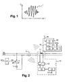
- the figure 1 represents the appearance of a parasitic pulse I naturally emitted by an electrical element when it is powered up.
- a parasitic pulse is independent of the electrical consumption of the electrical element and takes the form of a high frequency alternating wave train, typically of a frequency of the order of 20. MHz.
- the duration of this parasitic pulse is a few hundred nanoseconds, typically 250 nanoseconds.
- Its amplitude U can range from ten millivolt up to a few volts (under a voltage of 220 volts) depending on the reactive component of the element and the power it absorbs.
- the pulses collected are wider and of the order of ten microseconds, or a spreading by a factor of 40 of the initial impulse.
- the present invention proposes to control the emission, by an electrical element, of high frequency spurious pulses, to obtain a series of pulses having a desired profile, instead of artificially reproducing such pulses.
- the figure 2 illustrates the process according to the invention.
- An electrical element 1 is connected via a switch 2 to a power distribution network 3 carrying an alternating voltage Uac.
- the network 3 is here single-phase and the electric element 1 is connected to the phase wire (PH) and the neutral wire (NL) of the network, the switch 2 being interposed between the phase wire and the corresponding terminal of the electric element.
- the switch 2 comprises a control terminal to which is applied a control signal CS ensuring the control of the closing and opening of the switch.
- the switch 2 is of any suitable type, for example a monostable switch normally open type (MOS or bipolar transistor, monostable relay ...) or a bistable switch (triac, bistable relay ).
- the element 1 can be any type of electrical element producing parasitic pulses of desired shape (duration, amplitude, ...), for example a light bulb, a light-emitting diode (LED diode), a capacitor, a resistance of strong value or a combination of these elements.
- the electrical element preferably has a high impedance to prevent the appearance of a high switching current on the network.
- the control signal CS is a two-state signal "1" and "0", the "1" corresponding to a determined control voltage and the "0" corresponding to another determined control voltage, which can be the mass potential.
- the switch is closed (passing) when the signal CS is at 1 (monostable switch) or when the signal CS goes from 0 to 1 (bistable switch) and the switch is open (not passing) when the signal CS is at 0 or goes from 1 to 0.
- the signal CS is likely to be applied directly to the control terminal of the switch or via a stage d 'adaptation.
- the signal CS thus represents, in the sense of the invention, the logic control signal of the switch. It can constitute the primary control signal of the switch, that is to say the signal that is actually applied to the control terminal of the switch, if it is compatible with the electrical characteristics of this control terminal .
- the method according to the invention is based on the emission of high frequency pulses referred to herein and in the claims as “spurious" pulses, to distinguish them from artificially generated pulses.
- the term "parasite” does not mean that the process according to the invention is a producer of pests and is therefore incompatible with the legislation aimed at regulating pollution on electricity networks.
- the method according to the invention is less “intrusive” and less disruptive than conventional methods based on the injection into the electrical network of a carrier signal or the injection of capacitor discharge pulses.
- FIGS. 3A, 3B, 3C illustrate in more detail the process according to the invention.
- the figure 3A represents an example of any form of CS signal and the figure 3B represents the amplitude, in Volt, of the high frequency spurious pulses produced on the network 3.
- the figure 3C represents the waveform of the voltage Uac at the moment when the spurious pulses are emitted.
- the switch 2 becomes on (ON)
- the electrical element 1 receives the voltage Uac and a parasitic closing pulse I1, I3, I5 (or pulse connection) is issued.
- switch 2 goes into the open state (OFF)
- element 1 is disconnected from the network and a parasitic opening pulse I2, I4, I6 (or disconnect pulse) is issued.
- the parasitic closing pulse I1 is maximum because it is transmitted at a time t1 where the voltage Uac is equal to its peak value Umax (a parasitic pulse of the same amplitude would be obtained with the peak value -Umax).
- the closing parasitic pulses I3, I5 are emitted at times t3, t5 where the voltage Uac has a low amplitude, and have a much smaller amplitude than that of the pulse I1.
- the parasitic opening pulse I4 is emitted at a time t4 where the voltage Uac is less than its peak value Umax or -Umax, and has a smaller amplitude than the parasitic opening pulse I2.
- the parasitic opening pulse I2 although emitted at a time t2 when the voltage Uac is maximum (under the same conditions) has a magnitude significantly lower than that of the parasitic pulse I1.
- the parasitic opening pulse I6 is emitted at a time t6 where the voltage Uac is maximum (-Umax) and has a greater amplitude than those of the closing parasitic pulses I3, I5 which are transmitted under unfavorable conditions, and this despite the fact that the latter would be of greater amplitude if they were issued under the same conditions.
- the 3D figures, 3E illustrate a first embodiment of the method in which the opening parasitic pulses are neutralized on transmission.
- the 3D figure represents the shape of the CS signal and the figure 3E represents the amplitude of the pulses obtained.
- the signal CS is synchronized with the waveform of the voltage Uac, represented in FIG. figure 3C . More particularly, the signal CS goes to 1 when the voltage Uac is equal to Umax or -Umax and goes to 0 when the voltage Uac is zero. In other words, the switch 2 goes from the closed state to the open state when the voltage Uac is zero and the opening parasitic pulses are never transmitted, as appears in FIG. figure 3E .
- the amplitude of the parasite closing pulses is maximum since the switch is closed only at the moments when the voltage Uac is maximum.
- the signal profile CS represented in 3D figure is of course only a template determining the authorized times of closing and opening of the switch 2.
- various series of pulses each having a specific profile can be issued, each profile can be assigned to the identification of 'a particular electrical appliance, as envisaged by EP 1 136 829 but using synthetic pulses.
- this template is used to transmit data.
- DTx data to be transmitted possibly in coded form, are applied to a circuit 4 which provides the control signal CS while monitoring the voltage Uac.
- the sending of data can be done bit by bit or in the form of a frame comprising for example a start bit and 8 data bits, and possibly a signature field, for example a parity bit.
- a closing of the switch 2 ie the emission of a spurious pulse
- the absence of closing of the switch at the moment imposed by the template, ie no parasitic pulse corresponds to the sending of a bit to 0.
- the period T of the voltage Uac is 20 ms, so that 100 spurious pulses (ie 100 uncoded bits) can be sent in one second. Although this pulse rate is slow, it is sufficient for some applications of identification or data transmission, including an application to the management of a public lamp post park described below.
- a second embodiment of the method is provided for sending data or pulse trains with a higher rate.
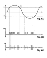
- This embodiment is illustrated by the Figures 4A, 4B, 4C .
- the parasitic closing pulses are not neutralized on transmission and are ignored on reception, thanks to an appropriate setting of a detection threshold.
- a threshold U1 close to the peak value Umax is chosen, for example a threshold equal to 0.66 Umax.
- this threshold makes it possible to define two transmission authorization time windows TW1, TW2 at each half-period T / 2 of the voltage Uac.
- the window TW1 includes the values of the voltage Uac positive and greater than U1 and the window TW2 includes the values of the voltage Uac negative and lower than -U1 (greater than U1 in absolute value).
- the Figure 4B represents the template of the control signal CS. This includes closing / opening pulse trains that are applied to the switch 2 within each time window TW1, TW2. As it appears in figure 4C each closing / opening pulse causes the transmission of two high frequency spurious pulses on the network, ie a parasitic closing pulse on the rising edge of the closing / opening pulse and a parasitic opening pulse on the falling edge. the closing / opening pulse. As indicated above, the parasitic opening pulses are of a much lower amplitude than that of the closing parasitic pulses and are intended to be filtered on reception.
- the duration of windows TW1, TW2 is of the order of 6 to 7 ms and the number of closing / opening pulses that can be sent is high.
- the minimum duration of each closing / opening pulse must be at least twice the duration of the spurious pulses, ie of the order of 10 to 20 microseconds.
- each time window may contain about 300 closing / opening pulses and thus offers a high data rate relative to the first embodiment of the method of the invention, of the order of 30000 pulses per second.
- the data can be sent in raw form, a bit then corresponding to a pulse, or in coded form by any appropriate coding protocol, a bit then corresponding to several pulses.
- the coded or non-coded data may be sent in the form of individual bits or in the form of a frame comprising a frame start field, a data field, and possibly an end-of-frame field that may comprise a CRC type check field or a check field. parity.
- the emission of high frequency spurious pulses may be provided only once per period instead of twice per period, for example when the voltage Uac is equal to + Umax (first embodiment) or is greater to + U1 (second embodiment).
- the figure 2 also shows schematically two exemplary embodiments of pulse detectors 10, 15 according to the invention.
- the detector 10 is an inductive reception device whose operating principle has already been described in EP 1 136 829 . It comprises an input transformer for extracting from the voltage Uac an image signal which is analyzed to detect the high frequency spurious pulses.
- the transformer may simply be formed by a coil 11 arranged around the phase wire (PH) of the network, at a source point of the current distribution, for example near an electric meter.
- the coil provides the image signal that is applied to a high pass filter 12 to suppress its low frequency AC component.
- sample hold AD converter sample hold analog digital converter 13
- the filter output is applied to a sample-and-hold analog digital converter 13 ("sample hold AD converter ") which provides digital samples of the filtered voltage Uac, in synchronization with a sampling period defining an observation window
- the choice of the sampling period and the duration of the observation window depends on the period of emission of the high frequency spurious pulses, ie the period between two closing / opening pulses If the spurious pulses are transmitted with a high frequency, according to the second embodiment of the method of the invention, the window of observation is chosen short enough to obtain a fineness of analysis for differentiating the pulses within the trains of pulses emitted.
- the analysis of the samples of the voltage Uac is provided by an analysis circuit 14, generally a specific logic circuit, which analyzes the amplitude of the received samples and detects the pulses of an amplitude greater than the rejection threshold parasitic closing pulses, to retain only the parasitic opening pulses.
- the circuit 14 thus reconstructs the control signal CS, and also de
- the detector 15 is a non-contact device comprising an antenna 16, an antenna amplifier 17 and a high-pass filter 18 for eliminating the signals of lower frequency than the pulses to be detected.
- This embodiment of a pulse detector according to the invention is based on the fact that the pulses High-frequency noise can be found both as electrical impulses on the network and as electromagnetic impulses that can be detected in the same way as any radio frequency signal.
- the detector 15 is preferably arranged near the pulse transmitter equipment, for example in the premises where the equipment is installed.
- the figure 5 represents a simple and inexpensive embodiment of a device 20 for transmitting pulses according to the invention, intended to be embedded in devices or in electrical equipment.
- the device 20 comprises two terminals T1, T2 for connection to the electricity distribution network 3, a switching circuit 30, a power supply circuit 40, a circuit 50 for monitoring the alternating voltage Uac and a control circuit 60.
- the terminal T1 is connected to the phase wire (PH) and the terminal T2 connected to the neutral wire (NL) of the network 3.
- the switching circuit 30 comprises an electric element 31, here a capacitor, and a switch 32.
- the switch 32 is for example a triac or a MOS transistor (a triac being represented on the figure 5 ).
- the switch 32 has a terminal connected to the terminal T1, another terminal connected to a terminal of the capacitor 31, and a control terminal (gate of the triac or gate of the MOS transistor) controlled by the control circuit 60.
- the other capacitor terminal 31 is connected to terminal T2.
- the supply circuit 40 comprises a diode rectifier bridge 41 having two input terminals connected to the terminals I1, I2 via resistors 42, 43, a grounded terminal and an output terminal providing a rectified voltage.
- the voltage Ur is applied to an input of a regulator block 46 which is connected to ground via an overvoltage clipping diode 44 and a smoothing capacitor 45.
- the output of FIG. Regulator block 46 is connected to a stabilizing capacitor 47 and supplies a supply voltage Vcc to circuits 50, 60.
- the monitoring circuit 50 comprises a diode rectifier bridge 51 having two input terminals connected to the terminals I1, I2 through resistors 52, 53, respectively, a grounded terminal and an output terminal providing a voltage straightened double alternation Ur '.
- the rectified voltage Ur ' is applied to the positive input of a differential amplifier 56 which is connected to ground via an overvoltage clipping diode 54 and a load resistor 55.
- the input negative of the amplifier 56 receives a reference voltage Vref provided by the midpoint of a potentiometer 57 whose anode receives the voltage Vcc and whose cathode is grounded.
- the differential amplifier 56 operating here as a comparator, provides an ENB ("Enable") signal which is at 1 (Vcc) when the full-wave rectified voltage Ur 'is greater than the reference voltage Vref, and is at 0 (mass ) on the other hand.
- ENB Enable
- the monitoring circuit 50 may comprise only a half-wave rectifier if it is expected that pulses are emitted only on one of the two half-periods of the voltage Uac.
- the circuit 60 supplies the control signal CS applied to the control terminal of the switch 32.
- the circuit 60 comprises a microcontroller 61 at low cost, incorporating on the same silicon chip a microprocessor and its P0 input / output ports. , P1, P2, P3 ..., a program memory, data memories, a crystal oscillator ...
- the port P0 receives the signal ENB
- the port P1 provides the control signal CS
- the ports P2 P3 are , optionally, used as communication ports of the microcontroller for test, maintenance, programming, ... and are connected to auxiliary terminals AT1, AT2 of the device 20.
- the microcontroller detects the transition to 1 of the signal ENB by polling (polling) port P0 or declared interruption on this port.
- the port P1 drives the switch 32 via an adapter stage comprising a control block 62 and a transistor 63.
- the control block 62 has an output connected to the control terminal of the switch 32 and an input connected to the collector of transistor 63, whose emitter is connected to ground and whose base receives the control signal CS.
- the device 20, once embedded in an electrical apparatus, is usable for transmitting data or, more simply, for transmitting a series of non-data carrying pulses having a predetermined invariable profile, serving for example for the identification of the 'electrical appliance.
- the circuit 60 may be a logic circuit of a rudimentary architecture, comprising a synchronization input receiving the signal ENB and providing the control signal CS.
- the device 20 can thus be the subject of various applications.
- An example of application is the control of lampposts in an agglomeration.
- each lamppost is equipped with such a device and cyclically sends information about its on or off status.
- This information can be sent at a low rate according to the first embodiment of the method of the invention, since it has no urgency and can be processed over periods of time of several minutes.
- hundreds of streetlights can be equipped with devices according to the invention.
- 60 streetlights can emit information in one minute.
- a reception unit arranged at a source point of the urban electricity distribution network or at a branch node is sufficient to receive the information sent by a plurality of street lamps.
- the pulse emitting device according to the invention may also be the subject of various embodiments depending on the intended applications.
- the figure 6 represents a device 20 'which comprises, in addition to the circuits 30, 40, 50 and 60 which have just been described, a current sensor 70 connected to a measurement circuit 71.
- the measurement circuit 71 sent to the control circuit 60 data relating to measurements of current carried out by means of the sensor 70.
- the microcontroller of the device 60 analyzes the results of the measurements and decides whether to send them or not according to what is provided in the application program loaded in its program memory.
- This program may for example provide that the microcontroller sends on the network information relating to the current measured only when it passes from 0 to a non-zero value, then moves from one consumption section to another, for example from the slice ranging from 0 to 1 A to the range of 1 to 2 A, the range from 1 to 2 A to the range of 2 to 3 A, etc.
- This information can take the form of an eight-bit word (byte) having a first value when the measured current changes from 0 to a non-zero value, then a second value when the current changes from 0-1 A to the slice 1-2 A, etc.
- the device 20 ' can be arranged in an electrical socket, in particular a socket socket used to electrically power one or more devices, or be embedded in an electrical device, in order to measure the current flowing through the electrical socket or the current consumed by the device in which it is embedded.
- an application makes it possible to improve the method for measuring the electrical consumption of electrical appliances described by EP 1 136 829 . Indeed, when the current goes from 0 to a non-zero value, the transmission of the first byte makes it possible to identify on the network the apparatus or the group of apparatus which is energized. Then, the emission of bytes in relation to the change of consumption slice makes it possible to confirm the measurements of consumption and location made on the network in the manner proposed by EP 1 136 829 .
- circuit breakers grouped together in electrical cabinets, whose closed (latched) or open (tripped) state must be monitored.
- breakers have been developed in the state of the art equipped with a control switch which, by means of a mechanical actuator, switches from the open state to the closed state when the circuit breakers switch off.
- the circuit breakers arranged in large numbers in electrical cabinets each have a witness switch connected by two wires to a centralizer, which monitors the state of the circuit breakers for the detection of power outages.
- the present invention proposes to eliminate the amounts of electrical son connecting the control switches to the centralizer, by boarding a circuit breaker a device according to the invention which is arranged to monitor the state of the circuit breaker and send information when the circuit breaker is in the circuit breaker. open state.
- This information may for example consist in a circuit breaker identification code, whose only transmission means that the circuit breaker has tripped.
- the figure 7 represents an exemplary embodiment of a circuit breaker 90 according to the invention, comprising a combination of a conventional circuit breaker 80 and a device 20 according to the invention.
- the structure of the device 20 is identical to that described in relation to the figure 5 and will not be described again.
- the circuit breaker 80 comprises input terminals T3, T4 connected to the phase and neutral wires of the upstream portion of the electricity distribution network, and output terminals T5, T6 connected to the phase and neutral wires of the downstream part of the electricity distribution network.
- the circuit breaker 80 also comprises control terminals T7, T8 connected to the terminals of a 81.
- the terminals T1 and T2 of the device 20 are connected to the terminals T3 and T4 of the circuit breaker 80 so that the device 20 is electrically powered when the circuit breaker is in the open state.
- the detection by the device 20 of the state of the circuit breaker 80 is ensured here by means of the control switch.
- the microcontroller of the control circuit 60 may comprise two input / output ports connected to the terminals T7, T8 to cyclically monitor the on or off state of the control switch.
- this solution has the disadvantage that the device 20 must be permanently energized, and involves an electrical consumption.
- the integration of the device 20 in a circuit breaker 80 to obtain the circuit breaker 90 according to the invention involves a small increase in the cost price of the circuit breaker, and in return saves significant cabling savings due to the elimination of electrical wires connecting the centralizer and the circuit breakers.
- a pulse receiver of the type described above allows for a wireless centralizer capable of handling hundreds of circuit breakers and providing in real time an indication on circuit breakers in the tripped state.
- the present invention is susceptible of various other embodiments and applications.
- various applications of the method of the invention have been described to an electrical network carrying an alternating voltage
- the present invention is also applicable to DC networks, including 400V DC networks used in industry or on board ships, 200V DC networks, including 12V DC low voltage networks in motor vehicles.
- the method according to the invention can be used to cause a vehicle body (for example a car headlight) to transmit information concerning its state (on, off, out of service, etc.).
- a vehicle body for example a car headlight
- the monitoring of the waveform of the voltage carried by the network is no longer necessary since this voltage, being continuous, always has an optimum value for the emission of high frequency spurious pulses. .
- the invention being based on a phenomenon little studied so far, it is up to those skilled in the art to complete the teaching just described by experimental observations.
- complementary experiments have revealed that the amplitude of the parasitic connection pulses may be equal to or even greater than that of the disconnection spurious pulses.
- a low-value resistor for example a few ohms, which is cyclically connected to the network with a very short connection time, for example a few microseconds, and which is thus traversed by a high current, for example several amperes, which does not disturb the network because of its short duration.
- the amplitude of the spurious pulses emitted when the resistance is disconnected from the network is substantially greater than that of the spurious pulses emitted when the resistor is connected to the network.
- the disconnection pulses can also be used as means for transmitting information, instead of the connection pulses.
- the pulses of both types, of connection and disconnection can both be detected to obtain redundant pulse detection information for reconstructing the control signal with increased reliability.
Landscapes
- Engineering & Computer Science (AREA)
- Power Engineering (AREA)
- Physics & Mathematics (AREA)
- General Physics & Mathematics (AREA)
- Computer Networks & Wireless Communication (AREA)
- Signal Processing (AREA)
- Remote Monitoring And Control Of Power-Distribution Networks (AREA)
- Cable Transmission Systems, Equalization Of Radio And Reduction Of Echo (AREA)
- Small-Scale Networks (AREA)
- Electrotherapy Devices (AREA)
- Management, Administration, Business Operations System, And Electronic Commerce (AREA)
- Dc Digital Transmission (AREA)
Claims (32)
- Verfahren zum Übertragen einer Information über ein eine Spannung (Uac) führendes Elektrizitätsverteilernetz (3), das die folgenden Schritte umfasst:- das Zwischenschalten eines elektrischen Elements (1, 31) zwischen zwei Leitungen (PH, NL) des Netzes in Serie mit einem Schaltermittel (2, 32),- das Anlegen eines Steuersignals (CS) mit bestimmter Form an das Schaltermittel, sodass das Schaltermittel in der Folge geschlossen oder geöffnet wird,dadurch gekennzeichnet, dass es Folgendes umfasst:- einen Schritt des Detektierens von Störimpulsen, die im Netz auftreten, wenn das Schaltermittel geschlossen oder geöffnet ist, wobei jeder Störimpuls einen hochfrequenten Wellenzug umfasst, und- einen Schritt des Wiederherstellens des Steuersignals (CS).
- Verfahren nach Anspruch 1, wobei das Schaltermittel (2, 32) von einem Steuersignal (CS) gesteuert ist, das Daten (DTx) trägt, sodass hochfrequente Störimpulse, die Daten tragen, im Rhythmus des Steuersignals ausgegeben werden.
- Verfahren nach Anspruch 2, wobei das Steuersignal (CS) ein codiertes Signal ist.
- Verfahren nach einem der Ansprüche 1 bis 3, wobei das Elektrizitätsverteilernetz (3) eine Wechselspannung (Uac) führt und wobei das Steuersignal (CS) auf die Wellenformen der Wechselspannung (Uac) synchronisiert ist, sodass der Schalter (2, 32) nur dann geschlossen ist, wenn sich die Wechselspannung im Bereich ihres Spitzenwerts (Umax, -Umax) befindet.
- Verfahren nach Anspruch 4, wobei die Wechselspannung (Uac) als im Bereich ihres Spitzenwerts befindlich betrachtet wird, wenn sie eine Amplitude (U1, U2) von mindestens gleich 50 % ihres Spitzenwerts aufweist.
- Verfahren nach einem der Ansprüche 4 oder 5, wobei das Steuersignal (CS) auf die Wellenform der Wechselspannung synchronisiert ist, sodass der Schalter nur dann offen ist, wenn sich die Wechselspannung im Bereich von null befindet.
- Verfahren nach einem der Ansprüche 1 bis 6, wobei das Steuersignal (CS) aus Impulsen zum Schließen/Öffnen des Schaltermittels von konstanter Dauer besteht, wobei jeder Impuls zum Schließen/Öffnen eine ansteigende Front und/oder eine hohe Höhe umfasst, die eine Änderung des offenen oder geschlossenen Zustands des Schalters bewirkt, und eine absteigende Front und/oder eine niedrige Höhe umfasst, die eine umgekehrte Änderung des Zustands des Schalters bewirkt.
- Verfahren nach Anspruch 7, wobei das Steuersignal Impulse zum Schließen/Öffnen mit einer Dauer umfasst, die geringer ist als 1/8 der Periode der Wechselspannung.
- Verfahren nach einem der Ansprüche 1 bis 8, wobei das elektrische Element ein Kondensator (31), ein Widerstand, eine Leuchtdiode oder eine Kombination aus mindestens zwei dieser Elemente ist.
- Verfahren nach einem der Ansprüche 1 bis 9, wobei Störimpulse neutralisiert, gesperrt oder ignoriert werden und bei der Wiederherstellung des Steuersignals nicht berücksichtigt werden.
- Verfahren nach Anspruch 10, wobei die Detektion der Störimpulse das Erzeugen eines Spiegelsignals der vom Elektrizitätsverteilernetz geführten Spannung, das Hochpassfiltern (12) des Spiegelsignals, das Abtasten (13) des Spiegelsignals gemäß einem bestimmten Abtastfenster, um digitale Proben des Spiegelsignals zu erhalten, und das Analysieren (14) der Proben des Spiegelsignals umfasst.
- Verfahren zum Fernmessen des lokalen Elektrizitätsverbrauchs eines mit einem Elektrizitätsverteilernetz (3), das eine bestimmte Spannung (Uac) führt, verbundenen elektrischen Geräts, das einen Schritt des Messen des Elektrizitätsverbrauchs der Vorrichtung mittels eines eingebauten Stromsensors (70, 71), einen Schritt des Ausgebens und einen Schritt des Empfangens einer Information über den Elektrizitätsverbrauch umfasst und das gemäß dem Verfahren nach einem der Ansprüche 2 bis 11 durchgeführt wird.
- Verfahren zum Identifizieren eines mit einem Elektrizitätsverteilernetz (3), das eine bestimmte Spannung (Uac) führt, verbundenen elektrischen Geräts, dadurch gekennzeichnet, dass es einen Schritt des Ausgebens einer Abfolge von hochfrequenten Störimpulsen, die einen Identifikationscode des Geräts bilden, umfasst und es gemäß dem Verfahren nach einem der Ansprüche 1 bis 11 durchgeführt wird.
- Verfahren nach Anspruch 13, wobei das elektrische Gerät ein Schutzschalter (80) ist, wobei die Ausgabe des Identifikationscodes nur dann veranlasst wird, wenn der Schutzschalter abgeschaltet hat.
- Vorrichtung zum Ausgeben und Empfangen einer Information über ein eine Spannung (Uac) führendes Elektrizitätsverteilernetz (3), die Folgendes umfasst:- eine Vorrichtung (20, 20') zum Ausgeben von Impulsen im Netz (3), umfassend:- ein elektrisches Element (31) und ein Schaltermittel (32), die zwischen zwei Leitungen (PH, NL) des Netzes in Serie geschaltet sind; und- Mittel (60, 61) zum Anlegen eines Steuersignals (CS) mit bestimmter Form an das Schaltermittel, sodass das Schaltermittel in der Folge geschlossen oder geöffnet wird,dadurch gekennzeichnet, dass sie Folgendes umfasst:- eine Vorrichtung (10, 15) zum Detektieren von Störimpulsen, die im Netz auftreten, wenn das Schaltermittel geschlossen oder geöffnet ist, wobei jeder Störimpuls einen hochfrequenten Wellenzug umfasst, wobei die Vorrichtung zum Detektieren Mittel (12, 13, 14, 16, 17) zum Wiederherstellen des Steuersignals (CS) umfasst.
- Vorrichtung nach Anspruch 15, umfassend Mittel (61) zum Bereitstellen eines Steuersignals (CS), das Daten trägt, an das Schaltermittel.
- Vorrichtung nach Anspruch 16, umfassend Mittel (61) zum Bereitstellen eines codierten Steuersignals (CS) an das Schaltermittel.
- Vorrichtung nach einem der Ansprüche 15 bis 17, die für ein Elektrizitätsverteilernetz (3), das eine Wechselspannung (Uac) führt, vorgesehen ist, wobei die Vorrichtung zum Ausgeben von Impulsen Mittel (50) zum Überwachen der Amplitude der Wechselspannung (Uac) umfasst, die ein Signal (ENB) zur Autorisierung der Ausgabe von Impulsen mit einem bestimmten Wert bereitstellen, wenn sich die Wechselspannung im Bereich ihres Spitzenwerts (Umax, -Umax) befindet, und Mittel umfasst, um den Schalter nur dann zu schließen, wenn das Signal zur Autorisierung der Ausgabe von Impulsen den bestimmten Wert aufweist.
- Vorrichtung nach Anspruch 18, wobei die Mittel zum Überwachen (50) ein Signal zur Autorisierung der Ausgabe von Impulsen mit dem bestimmten Wert bereitstellen, wenn die Amplitude der Wechselspannung einen Wert von mindestens 50 % ihres Spitzenwerts aufweist.
- Vorrichtung nach einem der Ansprüche 18 oder 19, wobei die Mittel zum Überwachen (50) einen Gleichrichter (51) umfassen, der eine einweg- oder zweiweggleichgerichtete Spannung (Ur') bereitstellt, deren Amplitude für die Amplitude der Wechselspannung (Uac) repräsentativ ist, und einen Vergleicher (56) umfassen, der an einem Eingang eine Referenzspannung (Vref) und an einem anderen Eingang die gleichgerichtete Spannung (Ur') empfängt und das Signal (ENB) zur Autorisierung der Ausgabe von Daten bereitstellt.
- Vorrichtung nach einem der Ansprüche 15 bis 20, wobei die Mittel (60, 61) zum Bereitstellen des Steuersignals ein Steuersignal (CS) bereitstellen, das aus Impulsen zum Schließen/Öffnen des Schaltermittels von konstanter Dauer besteht, wobei jeder Impuls eine ansteigende Front und/oder eine hohe Höhe umfasst, die eine Änderung des offenen oder geschlossenen Zustands des Schalters bewirkt, und eine absteigende Front und/oder eine niedrige Höhe umfasst, die eine umgekehrte Änderung des Zustands des Schalters bewirkt.
- Vorrichtung nach Anspruch 21 oder einem der Ansprüche 18 bis 20, wobei die Mittel (60, 61) zum Bereitstellen des Steuersignals Impulse zum Schließen/Öffnen mit einer Dauer bereitstellen, die mindestens geringer ist als 1/8 der Periode der Wechselspannung.
- Vorrichtung nach einem der Ansprüche 15 bis 22, wobei das elektrische Element ein Kondensator (31), ein Widerstand, eine Leuchtdiode oder eine Kombination aus mindestens zwei dieser Elemente ist.
- Vorrichtung nach einem der Ansprüche 15 bis 23, wobei das Schaltermittel ein Triac (32), ein MOS-Transistor oder ein Relais ist.
- Vorrichtung nach einem der Ansprüche 15 bis 24, wobei das Steuersignal (CS) von einem Mikrocontroller oder einem Mikroprozessor (61) bereitgestellt wird.
- Vorrichtung (20') nach einem der Ansprüche 15 bis 25, wobei die Vorrichtung (20, 20') zum Ausgeben von Impulsen Mittel (70, 71) zum Messen von Strom umfasst und angeordnet ist, um eine Information über einen gemessenen Strom in Form von hochfrequenten Störimpulsen auszugeben.
- Vorrichtung nach einem der Ansprüche 15 bis 26, wobei die Vorrichtung zum Detektieren (10) Mittel (13, 14) zum Filtern, Sperren oder Ignorieren von Störimpulsen umfasst, um derartige Impulse bei der Wiederherstellung des Steuersignals nicht zu berücksichtigen.
- Vorrichtung nach einem der Ansprüche 15 bis 27, die für ein Elektrizitätsverteilernetz (3), das eine Wechselspannung (Uac) führt, vorgesehen ist, wobei die Vorrichtung zum Detektieren (10) Mittel zum Bereitstellen eines Spiegelsignals der Wechselspannung und Mittel (12) zum Hochpassfiltern des Spiegelsignals, um daraus die hochfrequenten Störimpulse zu extrahieren, umfasst.
- Vorrichtung nach einem der Ansprüche 15 bis 27, wobei die Vorrichtung zum Detektieren (15) eine Antenne (16) umfasst, um unter Verwendung einer elektromagnetischen Komponente der Störimpulse die hochfrequenten Störimpulse zu detektieren.
- Vorrichtung nach einem der Ansprüche 28 oder 29, wobei die Vorrichtung zum Detektieren (10, 15) Mittel (13) zum Abtasten des empfangenen Signals und Mittel (14) zum Analysieren der Proben des empfangenen Signals umfasst, um die Gegenwart von hochfrequenten Störimpulsen zu detektieren.
- Schutzschaltervorrichtung (90), die einen geschlossenen Zustand und einen offenen Zustand aufweist, dadurch gekennzeichnet, dass sie eine Vorrichtung zum Ausgeben von Impulsen (20) nach einem der Ansprüche 15 bis 25 umfasst, um eine bestimmte Abfolge von Impulsen auszugeben, wenn die Schutzschaltervorrichtung im offenen Zustand vorliegt.
- Schutzschaltervorrichtung nach Anspruch 31, umfassend einen Kontrollschalter (81), der vom offenen Zustand in den geschlossenen Zustand kippt, wenn die Schutzschaltervorrichtung vom geschlossenen Zustand in den offenen Zustand kippt, wobei die ganze oder ein Teil (50, 60) der Vorrichtung (20) zum Ausgeben von Impulsen über den Kontrollschalter (81) elektrisch gespeist wird, sodass die Vorrichtung zum Ausgeben von Impulsen inaktiv ist, solange der Schutzschalter im geschlossenen Zustand vorliegt.
Priority Applications (1)
| Application Number | Priority Date | Filing Date | Title |
|---|---|---|---|
| PL05778875T PL1759467T3 (pl) | 2004-06-21 | 2005-06-20 | Sposób i urządzenie do przekazu informacji przez elektryczną sieć energetyczną |
Applications Claiming Priority (2)
| Application Number | Priority Date | Filing Date | Title |
|---|---|---|---|
| FR0406727A FR2871890B1 (fr) | 2004-06-21 | 2004-06-21 | Procede et dispositif d'emission d'impulsions sur un reseau de distribution d'electricite |
| PCT/FR2005/001534 WO2006008381A1 (fr) | 2004-06-21 | 2005-06-20 | Procede et dispositif de transmission d'une information via un reseau de distribution d’electricite |
Publications (2)
| Publication Number | Publication Date |
|---|---|
| EP1759467A1 EP1759467A1 (de) | 2007-03-07 |
| EP1759467B1 true EP1759467B1 (de) | 2008-08-13 |
Family
ID=34947368
Family Applications (1)
| Application Number | Title | Priority Date | Filing Date |
|---|---|---|---|
| EP05778875A Expired - Lifetime EP1759467B1 (de) | 2004-06-21 | 2005-06-20 | Verfahren und vorrichtung zur informationsübertragung in einem stromverteilungsnetz |
Country Status (16)
| Country | Link |
|---|---|
| US (1) | US7078982B2 (de) |
| EP (1) | EP1759467B1 (de) |
| CN (1) | CN101002400B (de) |
| AT (1) | ATE405036T1 (de) |
| AU (1) | AU2005263831B2 (de) |
| BR (1) | BRPI0512365A (de) |
| CA (1) | CA2570691C (de) |
| DE (1) | DE602005008961D1 (de) |
| DK (1) | DK1759467T3 (de) |
| ES (1) | ES2313404T3 (de) |
| FR (1) | FR2871890B1 (de) |
| MX (1) | MXPA06014487A (de) |
| PL (1) | PL1759467T3 (de) |
| PT (1) | PT1759467E (de) |
| RU (1) | RU2373643C2 (de) |
| WO (1) | WO2006008381A1 (de) |
Families Citing this family (21)
| Publication number | Priority date | Publication date | Assignee | Title |
|---|---|---|---|---|
| FR2871890B1 (fr) * | 2004-06-21 | 2006-10-13 | Watteco Soc Par Actions Simpli | Procede et dispositif d'emission d'impulsions sur un reseau de distribution d'electricite |
| EP1787371A2 (de) * | 2004-09-10 | 2007-05-23 | Cooper Technologies Company | System und verfahren zur überwachung und verwaltung einer überstromsicherung |
| US7948231B2 (en) * | 2004-12-14 | 2011-05-24 | Ntn Corporation | Rotation detecting apparatus having magnetic sensor array and bearing provided with same |
| US7848897B2 (en) | 2008-01-30 | 2010-12-07 | Southern Company Services, Inc. | Dynamic real-time power system monitoring |
| FR2929058B1 (fr) * | 2008-03-20 | 2014-01-10 | Watteco | Coupleur d'interface a commande basse tension pour emetteur multipulse |
| DE202010005953U1 (de) | 2009-07-24 | 2011-02-24 | Aizo Ag | Gestaltete Sinuskurve und eine Vorrichtung zum Gestalten einer Sinuskurve und Wiederauslesen der gestalteten Sinuskurve einer elektrischen Versorgung in einem Stromnetz |
| DE102010003597A1 (de) * | 2010-04-01 | 2011-10-06 | Tridonic Gmbh & Co Kg | Netzspannungs-Sendezweig einer Schnittstelle eines Betriebsgeräts für Leuchtmittel |
| FR2961312B1 (fr) | 2010-06-14 | 2012-07-13 | Schneider Electric Ind Sas | Dispositif et procede de comptage d'energie electrique. |
| DE102010052663B4 (de) * | 2010-11-26 | 2016-03-10 | Abb Ag | Übertragungssystem zur Übertragung von Datentelegrammen über eine Lastleitung |
| EP2485406B1 (de) * | 2011-02-07 | 2017-03-15 | Sony Corporation | Stromleitungskommunikationsvorrichtung mit Wechselstromstecker |
| WO2013001395A1 (en) | 2011-06-30 | 2013-01-03 | Koninklijke Philips Electronics N.V. | Active power identification for load monitoring system |
| SM201100038B (it) * | 2011-08-11 | 2012-09-07 | Gia Servizi Srl | Apparato di telecontrollo per trasmisione simultanea di segnali plurimi con tecnologia powerline. |
| KR101351529B1 (ko) * | 2012-05-21 | 2014-01-16 | (주)로보티즈 | 범용 주변 장치 인터페이스, 인터페이싱 방법 및 이를 가지는 로봇용 제어 장치 |
| US9065544B2 (en) * | 2012-09-28 | 2015-06-23 | Osram Sylvania Inc. | Pulse-based binary communication |
| AT513542B1 (de) | 2012-11-15 | 2014-07-15 | Fronius Int Gmbh | Verfahren und Anordnung zur Datenkommunikation zwischen einem Wechselrichter und einer Netzüberwachungseinheit |
| JP6390877B2 (ja) * | 2015-09-29 | 2018-09-19 | パナソニックIpマネジメント株式会社 | 符号変調器、符号復調器、及び、コントローラ |
| CN107241162B (zh) * | 2016-11-24 | 2020-04-10 | 天地融科技股份有限公司 | 一种数据传输方法及装置 |
| CN107171280A (zh) * | 2017-07-01 | 2017-09-15 | 合肥东玖电气有限公司 | 一种大能容过电压保护器 |
| CN109525283B (zh) * | 2017-09-18 | 2021-05-28 | 丰郅(上海)新能源科技有限公司 | 在太阳能发电系统中实现载波信号发送及接收的方法 |
| CN113092925B (zh) * | 2021-05-08 | 2022-12-06 | 辽宁汉华信息工程有限公司 | 配电网拓扑结构识别装置 |
| CN114678956B (zh) * | 2022-04-01 | 2025-08-26 | 北京航天鸣镝科技有限公司 | 基于脉冲电流的智能楼宇管理系统及方法 |
Family Cites Families (16)
| Publication number | Priority date | Publication date | Assignee | Title |
|---|---|---|---|---|
| GB1153908A (en) * | 1966-11-07 | 1969-06-04 | London Electricity Board | Information Transmission Systems |
| US3714451A (en) * | 1971-07-12 | 1973-01-30 | Franklin Electric Co Inc | Phase selective telemetry system |
| US4090184A (en) * | 1976-07-15 | 1978-05-16 | Hamilton Ii William F | Touch controlled switch system operable by touch inputs and coded message signals transmitted over power line |
| CA1128162A (en) * | 1977-11-17 | 1982-07-20 | Paul E. Belcher | Remote ac power control with control pulses at the zero crossing of the ac wave |
| SU1517140A1 (ru) * | 1987-12-25 | 1989-10-23 | Автомобильный завод им.Ленинского комсомола | Устройство дл передачи и приема сигналов управлени по двухпроводной линии св зи |
| US4982175A (en) * | 1989-08-25 | 1991-01-01 | Franklin Electric Co., Inc. | Telemetry circuit with noise immunization |
| RU2027306C1 (ru) * | 1992-11-12 | 1995-01-20 | Александр Яковлевич Вольский | Система передачи информации по линиям проводного вещания |
| US5486805A (en) * | 1993-07-06 | 1996-01-23 | Distribution Control Systems, Inc. | Method of receiving unsolicited messages on an electrical distribution network communications system |
| US5483153A (en) * | 1994-03-24 | 1996-01-09 | Massachusetts Institute Of Technology | Transient event detector for use in nonintrusive load monitoring systems |
| US5614811A (en) * | 1995-09-26 | 1997-03-25 | Dyalem Concepts, Inc. | Power line control system |
| US5691691A (en) * | 1997-01-06 | 1997-11-25 | Motorola, Inc. | Power-line communication system using pulse transmission on the AC line |
| WO2000026679A1 (en) * | 1998-11-03 | 2000-05-11 | Unique Technologies, Llc. | Low cost electrical circuit breaker locater with passive transmitter and receiver |
| US6496104B2 (en) * | 2000-03-15 | 2002-12-17 | Current Technologies, L.L.C. | System and method for communication via power lines using ultra-short pulses |
| FR2806806B1 (fr) * | 2000-03-22 | 2002-11-29 | Conseil En Technologies Innova | Procede de mesure de la consommation electrique d'un element connecte a un reseau de distribution d'electricite |
| ES2550821T3 (es) * | 2002-01-24 | 2015-11-12 | Panasonic Corporation | Método de y sistema para comunicaciones de portadora por línea eléctrica |
| FR2871890B1 (fr) * | 2004-06-21 | 2006-10-13 | Watteco Soc Par Actions Simpli | Procede et dispositif d'emission d'impulsions sur un reseau de distribution d'electricite |
-
2004
- 2004-06-21 FR FR0406727A patent/FR2871890B1/fr not_active Expired - Fee Related
- 2004-11-24 US US10/997,307 patent/US7078982B2/en not_active Expired - Fee Related
-
2005
- 2005-06-20 CN CN2005800206323A patent/CN101002400B/zh not_active Expired - Fee Related
- 2005-06-20 DE DE602005008961T patent/DE602005008961D1/de not_active Expired - Lifetime
- 2005-06-20 AT AT05778875T patent/ATE405036T1/de active
- 2005-06-20 AU AU2005263831A patent/AU2005263831B2/en not_active Ceased
- 2005-06-20 WO PCT/FR2005/001534 patent/WO2006008381A1/fr not_active Ceased
- 2005-06-20 PL PL05778875T patent/PL1759467T3/pl unknown
- 2005-06-20 PT PT05778875T patent/PT1759467E/pt unknown
- 2005-06-20 RU RU2007102049/09A patent/RU2373643C2/ru not_active IP Right Cessation
- 2005-06-20 ES ES05778875T patent/ES2313404T3/es not_active Expired - Lifetime
- 2005-06-20 EP EP05778875A patent/EP1759467B1/de not_active Expired - Lifetime
- 2005-06-20 MX MXPA06014487A patent/MXPA06014487A/es active IP Right Grant
- 2005-06-20 CA CA2570691A patent/CA2570691C/fr not_active Expired - Fee Related
- 2005-06-20 BR BRPI0512365-8A patent/BRPI0512365A/pt not_active IP Right Cessation
- 2005-06-20 DK DK05778875T patent/DK1759467T3/da active
Also Published As
| Publication number | Publication date |
|---|---|
| DE602005008961D1 (de) | 2008-09-25 |
| RU2007102049A (ru) | 2008-07-27 |
| US20050280559A1 (en) | 2005-12-22 |
| ATE405036T1 (de) | 2008-08-15 |
| CA2570691A1 (fr) | 2006-01-26 |
| EP1759467A1 (de) | 2007-03-07 |
| CN101002400A (zh) | 2007-07-18 |
| CA2570691C (fr) | 2013-11-26 |
| AU2005263831B2 (en) | 2010-04-22 |
| DK1759467T3 (da) | 2008-12-01 |
| CN101002400B (zh) | 2012-07-04 |
| MXPA06014487A (es) | 2007-07-09 |
| US7078982B2 (en) | 2006-07-18 |
| FR2871890A1 (fr) | 2005-12-23 |
| PL1759467T3 (pl) | 2009-01-30 |
| RU2373643C2 (ru) | 2009-11-20 |
| PT1759467E (pt) | 2008-11-24 |
| AU2005263831A1 (en) | 2006-01-26 |
| WO2006008381A1 (fr) | 2006-01-26 |
| FR2871890B1 (fr) | 2006-10-13 |
| ES2313404T3 (es) | 2009-03-01 |
| BRPI0512365A (pt) | 2008-03-11 |
Similar Documents
| Publication | Publication Date | Title |
|---|---|---|
| EP1759467B1 (de) | Verfahren und vorrichtung zur informationsübertragung in einem stromverteilungsnetz | |
| EP1136829B1 (de) | Verfahren und Vorrichtung zum Messen des Verbrauchs eines Elementes in einem Elektrizitätsnetz | |
| CA2344241C (fr) | Procede et dispositif pour la localisation d'un defaut d'isolement d'un cable electrique | |
| FR3019303A1 (fr) | Dispositif de mesure d'au moins une grandeur physique d'une installation electrique | |
| EP1043678B1 (de) | Duplexübertragung in einem elektromagnetischen Transponder-System | |
| CA2718673A1 (fr) | Coupleur d'interface a commande basse tension pour emetteur multipulse | |
| FR2695286A1 (fr) | Système de détection et de signalisation de lampes défaillantes dans un réseau d'éclairage. | |
| FR2943780A1 (fr) | Procede de gestion du fonctionnement d'un capteur de teleinformation,et capteur associe. | |
| EP2597473A1 (de) | Verfahren und Vorrichtung zur Erkennung eines Shunts zwischen dem Leistungseingang und -ausgang eines elektrischen Stromzählers | |
| EP0393123A1 (de) | Elemente zur erregung und abtastung von am reifen befindlichen modulen in einem fahrzeugreifenüberwachungssystem. | |
| WO1992014291A1 (fr) | Dispositif de protection pour appareils, machines et installations electriques | |
| EP0966800B1 (de) | Steuervorrichtung für trägerstromübertragung auf einem niedervoltnetz | |
| EP1540845A1 (de) | Verfahren zur steuerung der aktivierung eines elektromechanischen betätigungsgliedes | |
| FR2946148A1 (fr) | Procede de determination de l'origine de pannes de courant | |
| FR2566539A1 (fr) | Procede d'identification de cables electriques et appareil pour la mise en oeuvre de ce procede | |
| FR2728423A1 (fr) | Systeme de telereleve des equipements de mesure et de controle des installations de distribution d'energie electrique | |
| EP0694893B1 (de) | Alarmdetektionsvorrichtung mit Stromschleifen und Bake zur Lokalisierung von Waterzonen für eine solche Vorrichtung | |
| FR2848351A1 (fr) | Paratonnerre a amorcage equipe de moyens de maintenance distants | |
| WO1991000990A1 (fr) | Dispositif pour le controle d'etancheite des reseaux de cables a gaine metallique | |
| BE1012757A5 (fr) | Dispositif securise d'ordres de telecommande centralisee, dispositif associe et procede mis en oeuvre. | |
| FR2908242A1 (fr) | Appareil concourant a la securite des personnes et la conservation du patrimoine dans un reseau d'energie alimente en courant continu et galvaniquement isole notamment en eclairage public | |
| EP1658509A1 (de) | System zum erkennen und finden von fehlern in einem elektrischen zaun | |
| FR2488069A1 (fr) | Installation de transmission de signaux par le reseau de distribution d'energie electrique | |
| FR2664059A1 (fr) | Dispositif de reperage des phases d'un reseau de distribution d'electricite polyphase basse tension. | |
| FR2841711A1 (fr) | Dispostif de detection et de localisation de defauts de transmission dans les reseaux hfc et procede de mise en oeuvre |
Legal Events
| Date | Code | Title | Description |
|---|---|---|---|
| PUAI | Public reference made under article 153(3) epc to a published international application that has entered the european phase |
Free format text: ORIGINAL CODE: 0009012 |
|
| 17P | Request for examination filed |
Effective date: 20061122 |
|
| AK | Designated contracting states |
Kind code of ref document: A1 Designated state(s): AT BE BG CH CY CZ DE DK EE ES FI FR GB GR HU IE IS IT LI LT LU MC NL PL PT RO SE SI SK TR |
|
| 17Q | First examination report despatched |
Effective date: 20070622 |
|
| DAX | Request for extension of the european patent (deleted) | ||
| GRAP | Despatch of communication of intention to grant a patent |
Free format text: ORIGINAL CODE: EPIDOSNIGR1 |
|
| GRAS | Grant fee paid |
Free format text: ORIGINAL CODE: EPIDOSNIGR3 |
|
| GRAA | (expected) grant |
Free format text: ORIGINAL CODE: 0009210 |
|
| AK | Designated contracting states |
Kind code of ref document: B1 Designated state(s): AT BE BG CH CY CZ DE DK EE ES FI FR GB GR HU IE IS IT LI LT LU MC NL PL PT RO SE SI SK TR |
|
| REG | Reference to a national code |
Ref country code: GB Ref legal event code: FG4D Free format text: NOT ENGLISH |
|
| REG | Reference to a national code |
Ref country code: CH Ref legal event code: EP |
|
| REG | Reference to a national code |
Ref country code: IE Ref legal event code: FG4D Free format text: LANGUAGE OF EP DOCUMENT: FRENCH |
|
| REF | Corresponds to: |
Ref document number: 602005008961 Country of ref document: DE Date of ref document: 20080925 Kind code of ref document: P |
|
| REG | Reference to a national code |
Ref country code: PT Ref legal event code: SC4A Free format text: AVAILABILITY OF NATIONAL TRANSLATION Effective date: 20081112 |
|
| REG | Reference to a national code |
Ref country code: SE Ref legal event code: TRGR |
|
| REG | Reference to a national code |
Ref country code: DK Ref legal event code: T3 |
|
| PG25 | Lapsed in a contracting state [announced via postgrant information from national office to epo] |
Ref country code: LT Free format text: LAPSE BECAUSE OF FAILURE TO SUBMIT A TRANSLATION OF THE DESCRIPTION OR TO PAY THE FEE WITHIN THE PRESCRIBED TIME-LIMIT Effective date: 20080813 |
|
| REG | Reference to a national code |
Ref country code: PL Ref legal event code: T3 |
|
| PG25 | Lapsed in a contracting state [announced via postgrant information from national office to epo] |
Ref country code: SI Free format text: LAPSE BECAUSE OF FAILURE TO SUBMIT A TRANSLATION OF THE DESCRIPTION OR TO PAY THE FEE WITHIN THE PRESCRIBED TIME-LIMIT Effective date: 20080813 Ref country code: FI Free format text: LAPSE BECAUSE OF FAILURE TO SUBMIT A TRANSLATION OF THE DESCRIPTION OR TO PAY THE FEE WITHIN THE PRESCRIBED TIME-LIMIT Effective date: 20080813 |
|
| REG | Reference to a national code |
Ref country code: ES Ref legal event code: FG2A Ref document number: 2313404 Country of ref document: ES Kind code of ref document: T3 |
|
| NLR4 | Nl: receipt of corrected translation in the netherlands language at the initiative of the proprietor of the patent | ||
| PG25 | Lapsed in a contracting state [announced via postgrant information from national office to epo] |
Ref country code: RO Free format text: LAPSE BECAUSE OF FAILURE TO SUBMIT A TRANSLATION OF THE DESCRIPTION OR TO PAY THE FEE WITHIN THE PRESCRIBED TIME-LIMIT Effective date: 20080813 Ref country code: SK Free format text: LAPSE BECAUSE OF FAILURE TO SUBMIT A TRANSLATION OF THE DESCRIPTION OR TO PAY THE FEE WITHIN THE PRESCRIBED TIME-LIMIT Effective date: 20080813 |
|
| PLBE | No opposition filed within time limit |
Free format text: ORIGINAL CODE: 0009261 |
|
| STAA | Information on the status of an ep patent application or granted ep patent |
Free format text: STATUS: NO OPPOSITION FILED WITHIN TIME LIMIT |
|
| 26N | No opposition filed |
Effective date: 20090514 |
|
| PG25 | Lapsed in a contracting state [announced via postgrant information from national office to epo] |
Ref country code: EE Free format text: LAPSE BECAUSE OF FAILURE TO SUBMIT A TRANSLATION OF THE DESCRIPTION OR TO PAY THE FEE WITHIN THE PRESCRIBED TIME-LIMIT Effective date: 20080813 |
|
| PG25 | Lapsed in a contracting state [announced via postgrant information from national office to epo] |
Ref country code: GR Free format text: LAPSE BECAUSE OF FAILURE TO SUBMIT A TRANSLATION OF THE DESCRIPTION OR TO PAY THE FEE WITHIN THE PRESCRIBED TIME-LIMIT Effective date: 20081114 |
|
| PG25 | Lapsed in a contracting state [announced via postgrant information from national office to epo] |
Ref country code: TR Free format text: LAPSE BECAUSE OF FAILURE TO SUBMIT A TRANSLATION OF THE DESCRIPTION OR TO PAY THE FEE WITHIN THE PRESCRIBED TIME-LIMIT Effective date: 20080813 |
|
| PG25 | Lapsed in a contracting state [announced via postgrant information from national office to epo] |
Ref country code: CY Free format text: LAPSE BECAUSE OF FAILURE TO SUBMIT A TRANSLATION OF THE DESCRIPTION OR TO PAY THE FEE WITHIN THE PRESCRIBED TIME-LIMIT Effective date: 20080813 |
|
| PGFP | Annual fee paid to national office [announced via postgrant information from national office to epo] |
Ref country code: ES Payment date: 20120614 Year of fee payment: 8 |
|
| PGFP | Annual fee paid to national office [announced via postgrant information from national office to epo] |
Ref country code: AT Payment date: 20120524 Year of fee payment: 8 |
|
| PGFP | Annual fee paid to national office [announced via postgrant information from national office to epo] |
Ref country code: IS Payment date: 20130522 Year of fee payment: 9 Ref country code: IE Payment date: 20130528 Year of fee payment: 9 Ref country code: DE Payment date: 20130523 Year of fee payment: 9 Ref country code: MC Payment date: 20130522 Year of fee payment: 9 Ref country code: LU Payment date: 20130530 Year of fee payment: 9 Ref country code: GB Payment date: 20130527 Year of fee payment: 9 Ref country code: CZ Payment date: 20130528 Year of fee payment: 9 Ref country code: CH Payment date: 20130527 Year of fee payment: 9 Ref country code: DK Payment date: 20130523 Year of fee payment: 9 Ref country code: SE Payment date: 20130527 Year of fee payment: 9 |
|
| PGFP | Annual fee paid to national office [announced via postgrant information from national office to epo] |
Ref country code: NL Payment date: 20130524 Year of fee payment: 9 Ref country code: HU Payment date: 20130613 Year of fee payment: 9 Ref country code: PT Payment date: 20130619 Year of fee payment: 9 Ref country code: PL Payment date: 20130529 Year of fee payment: 9 Ref country code: IT Payment date: 20130523 Year of fee payment: 9 Ref country code: BE Payment date: 20130523 Year of fee payment: 9 |
|
| PGFP | Annual fee paid to national office [announced via postgrant information from national office to epo] |
Ref country code: BG Payment date: 20130603 Year of fee payment: 9 |
|
| PGFP | Annual fee paid to national office [announced via postgrant information from national office to epo] |
Ref country code: FR Payment date: 20130726 Year of fee payment: 9 |
|
| REG | Reference to a national code |
Ref country code: DE Ref legal event code: R119 Ref document number: 602005008961 Country of ref document: DE |
|
| REG | Reference to a national code |
Ref country code: PT Ref legal event code: MM4A Free format text: LAPSE DUE TO NON-PAYMENT OF FEES Effective date: 20141222 |
|
| REG | Reference to a national code |
Ref country code: DK Ref legal event code: EBP Effective date: 20140630 |
|
| REG | Reference to a national code |
Ref country code: NL Ref legal event code: V1 Effective date: 20150101 |
|
| PG25 | Lapsed in a contracting state [announced via postgrant information from national office to epo] |
Ref country code: MC Free format text: LAPSE BECAUSE OF NON-PAYMENT OF DUE FEES Effective date: 20140630 Ref country code: LU Free format text: LAPSE BECAUSE OF NON-PAYMENT OF DUE FEES Effective date: 20140620 Ref country code: CZ Free format text: LAPSE BECAUSE OF NON-PAYMENT OF DUE FEES Effective date: 20140620 Ref country code: PT Free format text: LAPSE BECAUSE OF NON-PAYMENT OF DUE FEES Effective date: 20141222 Ref country code: SE Free format text: LAPSE BECAUSE OF NON-PAYMENT OF DUE FEES Effective date: 20140621 |
|
| REG | Reference to a national code |
Ref country code: CH Ref legal event code: PL |
|
| REG | Reference to a national code |
Ref country code: SE Ref legal event code: EUG |
|
| REG | Reference to a national code |
Ref country code: AT Ref legal event code: MM01 Ref document number: 405036 Country of ref document: AT Kind code of ref document: T Effective date: 20140620 |
|
| GBPC | Gb: european patent ceased through non-payment of renewal fee |
Effective date: 20140620 |
|
| PG25 | Lapsed in a contracting state [announced via postgrant information from national office to epo] |
Ref country code: IS Free format text: LAPSE BECAUSE OF FAILURE TO SUBMIT A TRANSLATION OF THE DESCRIPTION OR TO PAY THE FEE WITHIN THE PRESCRIBED TIME-LIMIT Effective date: 20141231 |
|
| REG | Reference to a national code |
Ref country code: IE Ref legal event code: MM4A |
|
| REG | Reference to a national code |
Ref country code: FR Ref legal event code: ST Effective date: 20150227 |
|
| PG25 | Lapsed in a contracting state [announced via postgrant information from national office to epo] |
Ref country code: NL Free format text: LAPSE BECAUSE OF NON-PAYMENT OF DUE FEES Effective date: 20150101 |
|
| REG | Reference to a national code |
Ref country code: DE Ref legal event code: R119 Ref document number: 602005008961 Country of ref document: DE Effective date: 20150101 |
|
| PG25 | Lapsed in a contracting state [announced via postgrant information from national office to epo] |
Ref country code: CH Free format text: LAPSE BECAUSE OF NON-PAYMENT OF DUE FEES Effective date: 20140630 Ref country code: LI Free format text: LAPSE BECAUSE OF NON-PAYMENT OF DUE FEES Effective date: 20140630 Ref country code: DE Free format text: LAPSE BECAUSE OF NON-PAYMENT OF DUE FEES Effective date: 20150101 Ref country code: HU Free format text: LAPSE BECAUSE OF NON-PAYMENT OF DUE FEES Effective date: 20140621 Ref country code: IE Free format text: LAPSE BECAUSE OF NON-PAYMENT OF DUE FEES Effective date: 20140620 Ref country code: BG Free format text: LAPSE BECAUSE OF NON-PAYMENT OF DUE FEES Effective date: 20150331 Ref country code: IT Free format text: LAPSE BECAUSE OF NON-PAYMENT OF DUE FEES Effective date: 20140620 |
|
| PG25 | Lapsed in a contracting state [announced via postgrant information from national office to epo] |
Ref country code: AT Free format text: LAPSE BECAUSE OF NON-PAYMENT OF DUE FEES Effective date: 20140620 Ref country code: GB Free format text: LAPSE BECAUSE OF NON-PAYMENT OF DUE FEES Effective date: 20140620 Ref country code: FR Free format text: LAPSE BECAUSE OF NON-PAYMENT OF DUE FEES Effective date: 20140630 |
|
| REG | Reference to a national code |
Ref country code: ES Ref legal event code: FD2A Effective date: 20150728 |
|
| PG25 | Lapsed in a contracting state [announced via postgrant information from national office to epo] |
Ref country code: DK Free format text: LAPSE BECAUSE OF NON-PAYMENT OF DUE FEES Effective date: 20140630 |
|
| REG | Reference to a national code |
Ref country code: PL Ref legal event code: LAPE |
|
| PG25 | Lapsed in a contracting state [announced via postgrant information from national office to epo] |
Ref country code: ES Free format text: LAPSE BECAUSE OF NON-PAYMENT OF DUE FEES Effective date: 20140621 |
|
| PG25 | Lapsed in a contracting state [announced via postgrant information from national office to epo] |
Ref country code: PL Free format text: LAPSE BECAUSE OF NON-PAYMENT OF DUE FEES Effective date: 20140620 |
|
| PG25 | Lapsed in a contracting state [announced via postgrant information from national office to epo] |
Ref country code: BE Free format text: LAPSE BECAUSE OF NON-PAYMENT OF DUE FEES Effective date: 20140630 |