EP1759385B1 - Method and apparatus for writing data to an optical disc - Google Patents
Method and apparatus for writing data to an optical disc Download PDFInfo
- Publication number
- EP1759385B1 EP1759385B1 EP05744767A EP05744767A EP1759385B1 EP 1759385 B1 EP1759385 B1 EP 1759385B1 EP 05744767 A EP05744767 A EP 05744767A EP 05744767 A EP05744767 A EP 05744767A EP 1759385 B1 EP1759385 B1 EP 1759385B1
- Authority
- EP
- European Patent Office
- Prior art keywords
- signal
- disc
- lpp
- output signal
- scaling
- Prior art date
- Legal status (The legal status is an assumption and is not a legal conclusion. Google has not performed a legal analysis and makes no representation as to the accuracy of the status listed.)
- Expired - Lifetime
Links
Images

Classifications
-
- G—PHYSICS
- G11—INFORMATION STORAGE
- G11B—INFORMATION STORAGE BASED ON RELATIVE MOVEMENT BETWEEN RECORD CARRIER AND TRANSDUCER
- G11B7/00—Recording or reproducing by optical means, e.g. recording using a thermal beam of optical radiation by modifying optical properties or the physical structure, reproducing using an optical beam at lower power by sensing optical properties; Record carriers therefor
- G11B7/004—Recording, reproducing or erasing methods; Read, write or erase circuits therefor
- G11B7/005—Reproducing
- G11B7/0053—Reproducing non-user data, e.g. wobbled address, prepits, BCA
-
- G—PHYSICS
- G11—INFORMATION STORAGE
- G11B—INFORMATION STORAGE BASED ON RELATIVE MOVEMENT BETWEEN RECORD CARRIER AND TRANSDUCER
- G11B7/00—Recording or reproducing by optical means, e.g. recording using a thermal beam of optical radiation by modifying optical properties or the physical structure, reproducing using an optical beam at lower power by sensing optical properties; Record carriers therefor
- G11B7/004—Recording, reproducing or erasing methods; Read, write or erase circuits therefor
- G11B7/0045—Recording
-
- G—PHYSICS
- G11—INFORMATION STORAGE
- G11B—INFORMATION STORAGE BASED ON RELATIVE MOVEMENT BETWEEN RECORD CARRIER AND TRANSDUCER
- G11B7/00—Recording or reproducing by optical means, e.g. recording using a thermal beam of optical radiation by modifying optical properties or the physical structure, reproducing using an optical beam at lower power by sensing optical properties; Record carriers therefor
- G11B7/007—Arrangement of the information on the record carrier, e.g. form of tracks, actual track shape, e.g. wobbled, or cross-section, e.g. v-shaped; Sequential information structures, e.g. sectoring or header formats within a track
- G11B7/00736—Auxiliary data, e.g. lead-in, lead-out, Power Calibration Area [PCA], Burst Cutting Area [BCA], control information
Definitions
- the present invention relates to a method and apparatus for writing data to an optical disc.
- Optical discs such as DVD-R and DVD-RW discs to which information can be written, and optionally re-written as required, are becoming increasingly common as the primary medium for storing digital data.
- Such discs generally include a microscopic spiral groove arranged to provide a feedback signal to the optical writing unit of an optical disc drive so as to achieve accurate tracking during the writing of data to, at the reading of data from, the optical disc.
- Such a groove is generally formed by adjacent spiral lands and grooves.
- Embossed microstructures in the form of Land Pre-Pits are commonly provided within the lands of an optical disc and which are generally employed to provide disc-addressing information and related auxiliary data.
- LPP Land Pre Pits
- the LPP signal is not generally employed during the writing of data to the disc.
- potential advantages such as the verification and disc address, and fine-tuning of the write clock, can be achieved if the LPP signal is employed during the writing of data to the disc. In this manner, the quality with which data can be written to the disc is advantageously increased.
- US 2004/0071057 describes a method wherein a push-pull signal is detected from light reflected from a disk-shaped storage medium on which wobbling grooves are formed as recording tracks and address information is recorded by forming pre-pits on lands between adjacent grooves.
- a fundamental amplitude variation signal indicating the fundamental amplitude variation of the push-pull signal is acquired, and a reference voltage is generated by adding an offset voltage to the fundamental amplitude variation signal.
- Pre-pits are detected by comparing the push-pull signal with the reference voltage.
- the reference voltage is produced on the basis of the fundamental amplitude variation signal indicating the variation components of the push-pull signal due to the wobbling of grooves and noise, the variation components due to the wobbling and noise are reflected in the reference voltage. Furthermore, the variation components of the push-pull signal corresponding to the pre-pits are also reflected to a properly small extent in the reference voltage.
- the present invention seeks to provide for a method and apparatus for writing data to an optical disc and having advantages over known such methods and apparatus.
- a method of writing data to an optical disc comprising the steps of: obtaining an output signal from optical reading head; scaling the said output signal responsive to secondary data derived from the disc by way of the optical reading head; deriving a LPP signal for use during recording to the disc from the said scaled output signal wherein the said scaling is arranged to increase the LPP signal when the LPP is identified as located adjacent a space on the disc of low light reflectivity; characterised in that the said output signal comprises a balanced push-pull signal.
- Recording performance can advantageously be increased by way of the invention through advantageous use of the LPP signal generated during writing to the optical disc.
- the secondary data can comprise Eight to Fourteen Modulation (EFM) data or data derived from the peaks of a high frequency crosstalk signal derived from the disc.
- EFM Eight to Fourteen Modulation
- the balanced push-pull signal can be determined from the difference between a low pass filtered push-pull signal and a low pass filtered HF crosstalk signal.
- the scaling factor employed is arranged to comprise a constant value when a small HF crosstalk signal occurs.
- an apparatus for writing data to an optical disc comprising: means for obtaining an output signal from an optical reading head; means for scaling the said output signal responsive to secondary data obtained from said optical disc and by way of the output head; means for deriving a LPP signal for use during recording from the said scaled output signal, wherein the said scaling is arranged to increase the LPP signal when the LPP is located as being adjacent a space on the disc of low light reflectivity; characterised in that the said output signal comprises a balanced push-pull signal.
- the apparatus can further be arranged with appropriate means for providing the advantages discussed above in relation to the method of the present invention.
- Fig. 1 there is illustrated a section through part of an optical disc 10 to which data can be written and which comprises a spiral of grooves 12 upon which data marks 14 are written by means of an optical read/write head (not shown).
- the grooves 12 are separated by spiral lands 16.
- the upper edges of the lands 16 are formed with a sinusoidal configuration which is arranged to provide for a so-called wobble signal which is detected by the optical read/write head.
- This wobble signal is employed to assist with the accurate tracking of the optical read/write head as is well known in the art and so is not described any further here.
- FIG. 2 there is illustrated an arrangement 22 forming part of apparatus for writing data to an optical disc.
- a pair of low pass filters, 24, 26 arranged for receiving a high frequency crosstalk signal 28 and push-pull signal 30 respectively from analogue-digital converters associated with an optical read/write head (not shown).
- the signal output from the low pass filtered push-pull signal 30 is delivered to a difference unit 32 from which is derived a balanced push-pull signal 34.
- the balanced push-pull signal 34 is delivered to an integrator and dump unit 36 the output of which is in turn delivered to a PI controller 38.
- the units 36, 38 are arranged to provide a coefficient (COEF), which is combined, by way of multiplier 40 with the low pass filtered high frequency crosstalk signal 28.
- COEF coefficient
- the output from the multiplier 40 is then delivered to the difference unit 32 and, in combination with the low pass filtered push-pull signal 30, serves to produce the aforementioned balanced push-pull signal 34.
- the balanced push-pull signal 34 is also delivered to a multiplier 42 at which it is scaled by means of an output from a scaling unit 44.
- the scaled output is then delivered to a convolution arrangement 46 arranged to provide for convolution of the scaled balanced push-pull signal 34with a LPP-like wavelet W.
- the result of this convolution within the unit 46 is delivered to a band pass filter 148 from which the final LPP signal 50 is derived.
- the scaling unit 44 is arranged to provide one of a plurality of constants which can be determined by n levels of a generated EFMD signal from the EFM data clock.
- the constants can be derived from the amplitude levels of the HF crosstalk signal through detection of the peak and bottom levels of such signal where the number of levels "n" can be determined to calculate the standard deviation of the LPP signal in a digital signal processor, or similar digital hardware.
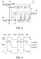
- FIG. 3 there is illustrated another embodiment of the present invention in which an additional multiplier is included for calculation of the coefficient and which serves to multiply the balanced push-pull signal with the low-passed filtered high frequency cross-talk signal.
- the arrangement 122 again forms part of an apparatus for writing to an optical disc comprising a pair of low pass filters 124,126 for receiving a HF crosstalk signal 128 and the push-pull signal 130 respectively.
- the low pass filtered push-pull signal 130 is delivered to a difference unit 132 from which is derived a balanced push pull signal 134.
- the balanced push-pull signal 134 is again delivered to a combination of an integrated dump unit 136 and a PI controller 138 although within this particular embodiment, the balanced push-pull signal 134 is delivered by way of a multiplier 152 at which the balanced push-pull signal 134 is multiplied with the low pass filtered HF crosstalk signal 128.
- the coefficient (COFF) is calculated on the basis of a multiplication of the balanced push-pull signal and the low pass filtered HF crosstalk signal and the values of the constants then employed within the scaling unit 144 can be confirmed during an optimum power calibration process before recording to a new disc.
- the larger of the constant values is selected in order to boast the relatively small balanced push-pull signal arising when the LPP is located adjacent relatively long spaces on the disc.
- the wavelet comprises the ideal form of the LPP waveform having length "k" is determined on the basis of the sampling rate, and recording speed, of the system.
- a bandpass filter 148 is included so as to remove DC components derived from the convolution signal so as to arrive at the final LPP signal 150.
- Fig. 4 there is provided a representation of the EFM data clock signal, and its relationship with the EFM data signal, the selection of three constant values to be applied at the scaling unit 44, and the resulting RF signals.
- the signal-to-noise ratio arising during LPP detection advantageously increases significantly during recording of the disc.
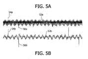
- FIGs. 5A and 5B there is illustrated a trace arising in accordance with the state of the art in Fig. 5A , and, for comparative purposes, a trace arising in accordance with the present invention in Fig. 5B .
- Fig. 5A there is illustrated the central trace of the high frequency wobble signal 52a and separate LPP signals 54a, 56a which, as will be appreciated, are not readily discernable from the wobble signal 52a.
- LPP signals 54b, 56b are readily discernable from a central trace of a wobble signal 52b.
- the LPP signal can be made readily available for use during writing to an optical disc such that recording performance when writing to discs such as DVD-R and DVD-RW disc is greatly improved. Advantages such as verified disc address and fine-tuning of the write clock can then be achieved.
- While the present invention can be advantageously applicable to recordable optical disc systems such as DVD-R and DVD-RW systems, it can likewise be readily implemented within system ICs and within a general optical disc specification.
Landscapes
- Optical Recording Or Reproduction (AREA)
Abstract
Description
- The present invention relates to a method and apparatus for writing data to an optical disc.
- Optical discs, such as DVD-R and DVD-RW discs to which information can be written, and optionally re-written as required, are becoming increasingly common as the primary medium for storing digital data.
- Such discs generally include a microscopic spiral groove arranged to provide a feedback signal to the optical writing unit of an optical disc drive so as to achieve accurate tracking during the writing of data to, at the reading of data from, the optical disc.
- Such a groove is generally formed by adjacent spiral lands and grooves. Embossed microstructures in the form of Land Pre-Pits are commonly provided within the lands of an optical disc and which are generally employed to provide disc-addressing information and related auxiliary data.
- In current DVD-R and DVD-RW recording systems, the signal produced when the optical head encounters the Land Pre Pits (LPP), i.e. the so-called LPP signal, is employed during playback of the disc.
- It is known that the LPP signal is not generally employed during the writing of data to the disc. However, it has been identified that potential advantages such as the verification and disc address, and fine-tuning of the write clock, can be achieved if the LPP signal is employed during the writing of data to the disc. In this manner, the quality with which data can be written to the disc is advantageously increased.
- However, in view of the large differences in laser power employed within the optical head when writing to the disc so as to achieve the required marks and spaces, it has been found that the LPP signal cannot readily be detected during such writing to the disc particularly when the LPP is located adjacent long spaces having low light reflectivity characteristics.
- Further, it is considered that known signal processing methods would not be appropriate for enhancing the detection of the LPP signal since the bandwidth of the LPP signal is closely similar to the bandwidth of larger writing signal pulses.
- For example,
US 2004/0071057 describes a method wherein a push-pull signal is detected from light reflected from a disk-shaped storage medium on which wobbling grooves are formed as recording tracks and address information is recorded by forming pre-pits on lands between adjacent grooves. A fundamental amplitude variation signal indicating the fundamental amplitude variation of the push-pull signal is acquired, and a reference voltage is generated by adding an offset voltage to the fundamental amplitude variation signal. Pre-pits are detected by comparing the push-pull signal with the reference voltage. Because the reference voltage is produced on the basis of the fundamental amplitude variation signal indicating the variation components of the push-pull signal due to the wobbling of grooves and noise, the variation components due to the wobbling and noise are reflected in the reference voltage. Furthermore, the variation components of the push-pull signal corresponding to the pre-pits are also reflected to a properly small extent in the reference voltage. - The present invention seeks to provide for a method and apparatus for writing data to an optical disc and having advantages over known such methods and apparatus.
- According to a first aspect of the present invention there is provided a method of writing data to an optical disc and comprising the steps of: obtaining an output signal from optical reading head; scaling the said output signal responsive to secondary data derived from the disc by way of the optical reading head; deriving a LPP signal for use during recording to the disc from the said scaled output signal wherein the said scaling is arranged to increase the LPP signal when the LPP is identified as located adjacent a space on the disc of low light reflectivity; characterised in that the said output signal comprises a balanced push-pull signal.
- Recording performance can advantageously be increased by way of the invention through advantageous use of the LPP signal generated during writing to the optical disc.
- Advantageously, the secondary data can comprise Eight to Fourteen Modulation (EFM) data or data derived from the peaks of a high frequency crosstalk signal derived from the disc.
- The balanced push-pull signal can be determined from the difference between a low pass filtered push-pull signal and a low pass filtered HF crosstalk signal.
- Advantageously, the scaling factor employed is arranged to comprise a constant value when a small HF crosstalk signal occurs.
- According to another aspect of the present invention there is provided an apparatus for writing data to an optical disc comprising: means for obtaining an output signal from an optical reading head; means for scaling the said output signal responsive to secondary data obtained from said optical disc and by way of the output head; means for deriving a LPP signal for use during recording from the said scaled output signal, wherein the said scaling is arranged to increase the LPP signal when the LPP is located as being adjacent a space on the disc of low light reflectivity; characterised in that the said output signal comprises a balanced push-pull signal.
- The apparatus can further be arranged with appropriate means for providing the advantages discussed above in relation to the method of the present invention.
- The invention is described further hereinafter, by way of example only, with reference to the accompanying drawings in which:
-
Fig. 1 is a partial perspective view of a section through an optical disc arranged to produce signals for processing in accordance with the present invention; -
Fig. 2 is a schematic block diagram illustrating an arrangement in accordance with one embodiment of the present invention; -
Fig. 3 is a schematic block diagram of an arrangement according to another embodiment of the present invention; -
Fig. 4 comprise timing diagrams illustrating the selection of constants employed for the required scaling within the present invention; and -
Figs. 5A and 5B comprise comparative traces of a LPP signal according to the prior-art and the present invention. - Turning now to
Fig. 1 , there is illustrated a section through part of anoptical disc 10 to which data can be written and which comprises a spiral ofgrooves 12 upon whichdata marks 14 are written by means of an optical read/write head (not shown). Thegrooves 12 are separated byspiral lands 16. As can be seen, the upper edges of thelands 16 are formed with a sinusoidal configuration which is arranged to provide for a so-called wobble signal which is detected by the optical read/write head. This wobble signal is employed to assist with the accurate tracking of the optical read/write head as is well known in the art and so is not described any further here. - Turning now to
Fig. 2 , there is illustrated anarrangement 22 forming part of apparatus for writing data to an optical disc. - Within the arrangement, there is provided a pair of low pass filters, 24, 26 arranged for receiving a high
frequency crosstalk signal 28 and push-pull signal 30 respectively from analogue-digital converters associated with an optical read/write head (not shown). - The signal output from the low pass filtered push-
pull signal 30 is delivered to adifference unit 32 from which is derived a balanced push-pull signal 34. - The balanced push-
pull signal 34 is delivered to an integrator anddump unit 36 the output of which is in turn delivered to aPI controller 38. Theunits frequency crosstalk signal 28. - The output from the
multiplier 40 is then delivered to thedifference unit 32 and, in combination with the low pass filtered push-pull signal 30, serves to produce the aforementioned balanced push-pull signal 34. - As illustrated, the balanced push-
pull signal 34 is also delivered to amultiplier 42 at which it is scaled by means of an output from ascaling unit 44. - The scaled output is then delivered to a
convolution arrangement 46 arranged to provide for convolution of the scaled balanced push-pull signal 34with a LPP-like wavelet W. - The result of this convolution within the
unit 46 is delivered to aband pass filter 148 from which thefinal LPP signal 50 is derived. - Within the illustrated embodiment of
Fig. 2 , thescaling unit 44 is arranged to provide one of a plurality of constants which can be determined by n levels of a generated EFMD signal from the EFM data clock. Alternatively the constants can be derived from the amplitude levels of the HF crosstalk signal through detection of the peak and bottom levels of such signal where the number of levels "n" can be determined to calculate the standard deviation of the LPP signal in a digital signal processor, or similar digital hardware. - Turning now to
Fig. 3 , there is illustrated another embodiment of the present invention in which an additional multiplier is included for calculation of the coefficient and which serves to multiply the balanced push-pull signal with the low-passed filtered high frequency cross-talk signal. - As illustrated, the structure of the embodiment of
Fig. 3 is as follows. - The
arrangement 122 again forms part of an apparatus for writing to an optical disc comprising a pair of low pass filters 124,126 for receiving aHF crosstalk signal 128 and the push-pull signal 130 respectively. - The low pass filtered push-
pull signal 130 is delivered to adifference unit 132 from which is derived a balancedpush pull signal 134. - The balanced push-
pull signal 134 is again delivered to a combination of an integrateddump unit 136 and aPI controller 138 although within this particular embodiment, the balanced push-pull signal 134 is delivered by way of a multiplier 152 at which the balanced push-pull signal 134 is multiplied with the low pass filteredHF crosstalk signal 128. - Thus, within an arrangement of
Fig. 3 , the coefficient (COFF) is calculated on the basis of a multiplication of the balanced push-pull signal and the low pass filtered HF crosstalk signal and the values of the constants then employed within thescaling unit 144 can be confirmed during an optimum power calibration process before recording to a new disc. - In general, the larger of the constant values is selected in order to boast the relatively small balanced push-pull signal arising when the LPP is located adjacent relatively long spaces on the disc.
- With regard to the convolution of the push-pull signal with a LPP-like wavelet W, the wavelet comprises the ideal form of the LPP waveform having length "k" is determined on the basis of the sampling rate, and recording speed, of the system.
- As with
Fig. 2 , abandpass filter 148 is included so as to remove DC components derived from the convolution signal so as to arrive at thefinal LPP signal 150. - Turning now to
Fig. 4 , there is provided a representation of the EFM data clock signal, and its relationship with the EFM data signal, the selection of three constant values to be applied at thescaling unit 44, and the resulting RF signals. - The signal-to-noise ratio arising during LPP detection advantageously increases significantly during recording of the disc.
- With regard to
Figs. 5A and 5B , there is illustrated a trace arising in accordance with the state of the art inFig. 5A , and, for comparative purposes, a trace arising in accordance with the present invention inFig. 5B . - With regard to
Fig. 5A , there is illustrated the central trace of the highfrequency wobble signal 52a andseparate LPP signals wobble signal 52a. - However, in accordance with the process and present invention, and as illustrated in
Fig. 5B ,LPP signals wobble signal 52b. - Thus, through use of the present invention, the LPP signal can be made readily available for use during writing to an optical disc such that recording performance when writing to discs such as DVD-R and DVD-RW disc is greatly improved. Advantages such as verified disc address and fine-tuning of the write clock can then be achieved.
- While the present invention can be advantageously applicable to recordable optical disc systems such as DVD-R and DVD-RW systems, it can likewise be readily implemented within system ICs and within a general optical disc specification.
- Through use of the re-scaling arrangement of the present invention advantageous improvements in recording quality can be achieved.
Claims (7)
- A method of writing data to an optical disc (10) and comprising the steps of:obtaining an output signal from optical reading head;scaling the said output signal responsive to secondary data derived from the disc (10) by way of the optical reading head;deriving a LPP signal (50; 150) for use during recording to the disc (10) from the said scaled output signal wherein the said scaling is arranged to increase the LPP signal (50; 150) when the LPP is identified as located adjacent a mark (14) on the disc (10) of low light reflectivity;characterised in that the said output signal comprises a balanced push-pull signal (34; 134).
- A method as claimed in Claim 1, wherein the secondary data comprises Eight to Fourteen Modulation (EFM) data.
- A method as claimed in Claim 1, wherein the secondary data is derived from the peaks of a high frequency crosstalk signal (28; 128) derived from the disc (10).
- A method as claimed in Claim 1, 2 or 3, wherein the push-pull signal can be determined from the difference between a low pass filtered push-pull signal (30; 130) and a low pass filtered HF crosstalk signal (28; 128).
- Apparatus for writing data to an optical disc (10) comprising:means for obtaining an output signal from an optical reading head;means for scaling the said output signal responsive to secondary data obtained from said optical disc (10) and by way of the output head;means for deriving a LPP signal (50; 150) for use during recording from the said scaled output signal, wherein the said scaling is arranged to increase the LPP signal (50; 150) when the LPP is located as being adjacent a mark (14) on the disc (10) of low light reflectivity;characterised in that the said output signal comprises a balanced push-pull signal (34; 134).
- Apparatus as claimed in Claim 5, wherein the secondary data comprises Eight to Fourteen Modulation data.
- Apparatus as claimed in Claim 5, wherein the secondary data is derived from the peaks of a high frequency crosstalk signal (28; 128) derived from the disc (10).
Applications Claiming Priority (2)
| Application Number | Priority Date | Filing Date | Title |
|---|---|---|---|
| GBGB0413396.3A GB0413396D0 (en) | 2004-06-16 | 2004-06-16 | Method and apparatus for writing data to an optical disc |
| PCT/IB2005/051833 WO2005124743A1 (en) | 2004-06-16 | 2005-06-06 | Method and apparatus for writing data to an optical disc |
Publications (2)
| Publication Number | Publication Date |
|---|---|
| EP1759385A1 EP1759385A1 (en) | 2007-03-07 |
| EP1759385B1 true EP1759385B1 (en) | 2008-04-30 |
Family
ID=32749959
Family Applications (1)
| Application Number | Title | Priority Date | Filing Date |
|---|---|---|---|
| EP05744767A Expired - Lifetime EP1759385B1 (en) | 2004-06-16 | 2005-06-06 | Method and apparatus for writing data to an optical disc |
Country Status (8)
| Country | Link |
|---|---|
| US (1) | US7872954B2 (en) |
| EP (1) | EP1759385B1 (en) |
| JP (1) | JP2008503019A (en) |
| CN (1) | CN100476960C (en) |
| AT (1) | ATE393953T1 (en) |
| DE (1) | DE602005006413T2 (en) |
| GB (1) | GB0413396D0 (en) |
| WO (1) | WO2005124743A1 (en) |
Family Cites Families (18)
| Publication number | Priority date | Publication date | Assignee | Title |
|---|---|---|---|---|
| NL9200808A (en) * | 1992-05-06 | 1993-12-01 | Philips Electronics Nv | OPTICAL WRITING AND / OR READING DEVICE. |
| JPH0917029A (en) | 1995-06-26 | 1997-01-17 | Pioneer Electron Corp | Optical disc, its reader, and optical disc manufacturing method |
| US7123555B2 (en) * | 1997-08-16 | 2006-10-17 | Lg Electronics Inc. | Information recording medium |
| US6754157B2 (en) * | 2000-08-07 | 2004-06-22 | Victor Company Of Japan, Limited | Recording and/or reproducing apparatus and recording and/or reproducing method capable of detecting a land pre-pit on disc securely at a high precision |
| JP2002216354A (en) * | 2001-01-15 | 2002-08-02 | Pioneer Electronic Corp | Pre-pit detection device |
| JP3791776B2 (en) * | 2001-02-06 | 2006-06-28 | パイオニア株式会社 | Pre-pit detection device for optical recording medium |
| JP2002260237A (en) | 2001-03-02 | 2002-09-13 | Victor Co Of Japan Ltd | Optical disk device |
| JP2002312944A (en) | 2001-04-17 | 2002-10-25 | Matsushita Electric Ind Co Ltd | Information recording and playback method |
| KR100484131B1 (en) * | 2001-12-04 | 2005-04-18 | 삼성전자주식회사 | Method and apparatus for detecting address information recorded on an optical disc by pre-pit |
| JP2003217127A (en) * | 2002-01-16 | 2003-07-31 | Sony Corp | Optical pickup device and optical disk device |
| JP3820181B2 (en) * | 2002-05-10 | 2006-09-13 | 株式会社リコー | Recording strategy generation method and optical information recording medium |
| JP3889673B2 (en) * | 2002-06-19 | 2007-03-07 | パイオニア株式会社 | Information recording apparatus and control method thereof |
| JP2004134002A (en) * | 2002-10-10 | 2004-04-30 | Sony Corp | Disk drive device, pre-pit detection method |
| JP4598355B2 (en) * | 2002-10-10 | 2010-12-15 | ソニー株式会社 | Disk drive device and pre-pit detection method |
| JP4357890B2 (en) * | 2003-08-08 | 2009-11-04 | パイオニア株式会社 | Land pre-pit detection apparatus and method |
| KR20050019622A (en) * | 2003-08-20 | 2005-03-03 | 삼성전자주식회사 | Land pre-pit data detection apparatus and method thereof |
| JP2005116079A (en) * | 2003-10-08 | 2005-04-28 | Matsushita Electric Ind Co Ltd | Land pre-pit address demodulator |
| KR100594739B1 (en) * | 2004-01-19 | 2006-06-30 | 삼성전자주식회사 | Pre-pit signal detection device and method |
-
2004
- 2004-06-16 GB GBGB0413396.3A patent/GB0413396D0/en not_active Ceased
-
2005
- 2005-06-06 US US11/629,770 patent/US7872954B2/en not_active Expired - Fee Related
- 2005-06-06 DE DE602005006413T patent/DE602005006413T2/en not_active Expired - Lifetime
- 2005-06-06 AT AT05744767T patent/ATE393953T1/en not_active IP Right Cessation
- 2005-06-06 JP JP2007516087A patent/JP2008503019A/en not_active Withdrawn
- 2005-06-06 EP EP05744767A patent/EP1759385B1/en not_active Expired - Lifetime
- 2005-06-06 WO PCT/IB2005/051833 patent/WO2005124743A1/en not_active Ceased
- 2005-06-06 CN CNB2005800197786A patent/CN100476960C/en not_active Expired - Fee Related
Also Published As
| Publication number | Publication date |
|---|---|
| CN1969326A (en) | 2007-05-23 |
| GB0413396D0 (en) | 2004-07-21 |
| CN100476960C (en) | 2009-04-08 |
| US20070140093A1 (en) | 2007-06-21 |
| DE602005006413D1 (en) | 2008-06-12 |
| DE602005006413T2 (en) | 2009-06-04 |
| WO2005124743A1 (en) | 2005-12-29 |
| ATE393953T1 (en) | 2008-05-15 |
| US7872954B2 (en) | 2011-01-18 |
| EP1759385A1 (en) | 2007-03-07 |
| JP2008503019A (en) | 2008-01-31 |
Similar Documents
| Publication | Publication Date | Title |
|---|---|---|
| KR100382138B1 (en) | Optical disc player and optical disc playback method | |
| JP4351813B2 (en) | Optical disk device | |
| EP2249343B1 (en) | Adjusting method for recording condition and optical disc device | |
| US7054246B2 (en) | Optical disk device adapted for reliably detecting pre-pit information formed on an optical disk | |
| US7187629B2 (en) | Method and related apparatus for deriving a tracking error signal | |
| US7391687B2 (en) | Method of determining recording power for recordable optical disk in optical disk system | |
| US7872954B2 (en) | Method and apparatus for writing data to an optical disc | |
| US8194518B2 (en) | Optical disc device and optical disc playback method | |
| JP2883538B2 (en) | Optical information reproducing device | |
| KR20060027343A (en) | Data to Push Pull Crosstalk Reduction Device and Method | |
| KR100829013B1 (en) | Wobble Addressing Method of Optical Disc Using Amplitude Shift Keying | |
| US7561503B2 (en) | Clock signal generating device and an optical disc apparatus incorporating the device | |
| US7054250B2 (en) | Method and device for jitter enhancement in an optical disc system | |
| US20040190415A1 (en) | Recorded information evaluation method and device and information recording medium therefor | |
| JP4794260B2 (en) | Disc player | |
| JP4268578B2 (en) | Optical disk device | |
| KR100301670B1 (en) | Apparatus for Controlling Recording of Optical Disc And Method Thereof | |
| US7796482B2 (en) | Land Pre-Pit signal processing method and related apparatus | |
| KR100829017B1 (en) | Wobble Addressing Method of Optical Disc Using Amplitude Shift Keying | |
| JP4618454B2 (en) | Timing signal generator | |
| JP4384995B2 (en) | Optical information recording apparatus and method, and signal processing circuit | |
| US7561501B2 (en) | Servo control device, optical disk drive, and servo control method | |
| JP2005149589A (en) | Optical disk device | |
| JP2002230903A (en) | Information playback device |
Legal Events
| Date | Code | Title | Description |
|---|---|---|---|
| PUAI | Public reference made under article 153(3) epc to a published international application that has entered the european phase |
Free format text: ORIGINAL CODE: 0009012 |
|
| 17P | Request for examination filed |
Effective date: 20070116 |
|
| AK | Designated contracting states |
Kind code of ref document: A1 Designated state(s): AT BE BG CH CY CZ DE DK EE ES FI FR GB GR HU IE IS IT LI LT LU MC NL PL PT RO SE SI SK TR |
|
| 17Q | First examination report despatched |
Effective date: 20070509 |
|
| RAP1 | Party data changed (applicant data changed or rights of an application transferred) |
Owner name: NXP B.V. |
|
| DAX | Request for extension of the european patent (deleted) | ||
| GRAP | Despatch of communication of intention to grant a patent |
Free format text: ORIGINAL CODE: EPIDOSNIGR1 |
|
| GRAS | Grant fee paid |
Free format text: ORIGINAL CODE: EPIDOSNIGR3 |
|
| GRAA | (expected) grant |
Free format text: ORIGINAL CODE: 0009210 |
|
| AK | Designated contracting states |
Kind code of ref document: B1 Designated state(s): AT BE BG CH CY CZ DE DK EE ES FI FR GB GR HU IE IS IT LI LT LU MC NL PL PT RO SE SI SK TR |
|
| REG | Reference to a national code |
Ref country code: GB Ref legal event code: FG4D |
|
| REG | Reference to a national code |
Ref country code: CH Ref legal event code: EP |
|
| REG | Reference to a national code |
Ref country code: IE Ref legal event code: FG4D Free format text: LANGUAGE OF EP DOCUMENT: FRENCH |
|
| REF | Corresponds to: |
Ref document number: 602005006413 Country of ref document: DE Date of ref document: 20080612 Kind code of ref document: P |
|
| PG25 | Lapsed in a contracting state [announced via postgrant information from national office to epo] |
Ref country code: SI Free format text: LAPSE BECAUSE OF FAILURE TO SUBMIT A TRANSLATION OF THE DESCRIPTION OR TO PAY THE FEE WITHIN THE PRESCRIBED TIME-LIMIT Effective date: 20080430 |
|
| NLV1 | Nl: lapsed or annulled due to failure to fulfill the requirements of art. 29p and 29m of the patents act | ||
| PG25 | Lapsed in a contracting state [announced via postgrant information from national office to epo] |
Ref country code: ES Free format text: LAPSE BECAUSE OF FAILURE TO SUBMIT A TRANSLATION OF THE DESCRIPTION OR TO PAY THE FEE WITHIN THE PRESCRIBED TIME-LIMIT Effective date: 20080810 Ref country code: NL Free format text: LAPSE BECAUSE OF FAILURE TO SUBMIT A TRANSLATION OF THE DESCRIPTION OR TO PAY THE FEE WITHIN THE PRESCRIBED TIME-LIMIT Effective date: 20080430 Ref country code: FI Free format text: LAPSE BECAUSE OF FAILURE TO SUBMIT A TRANSLATION OF THE DESCRIPTION OR TO PAY THE FEE WITHIN THE PRESCRIBED TIME-LIMIT Effective date: 20080430 Ref country code: PT Free format text: LAPSE BECAUSE OF FAILURE TO SUBMIT A TRANSLATION OF THE DESCRIPTION OR TO PAY THE FEE WITHIN THE PRESCRIBED TIME-LIMIT Effective date: 20080930 Ref country code: BG Free format text: LAPSE BECAUSE OF FAILURE TO SUBMIT A TRANSLATION OF THE DESCRIPTION OR TO PAY THE FEE WITHIN THE PRESCRIBED TIME-LIMIT Effective date: 20080730 |
|
| PG25 | Lapsed in a contracting state [announced via postgrant information from national office to epo] |
Ref country code: AT Free format text: LAPSE BECAUSE OF FAILURE TO SUBMIT A TRANSLATION OF THE DESCRIPTION OR TO PAY THE FEE WITHIN THE PRESCRIBED TIME-LIMIT Effective date: 20080430 Ref country code: PL Free format text: LAPSE BECAUSE OF FAILURE TO SUBMIT A TRANSLATION OF THE DESCRIPTION OR TO PAY THE FEE WITHIN THE PRESCRIBED TIME-LIMIT Effective date: 20080430 |
|
| PG25 | Lapsed in a contracting state [announced via postgrant information from national office to epo] |
Ref country code: IS Free format text: LAPSE BECAUSE OF FAILURE TO SUBMIT A TRANSLATION OF THE DESCRIPTION OR TO PAY THE FEE WITHIN THE PRESCRIBED TIME-LIMIT Effective date: 20080830 |
|
| ET | Fr: translation filed | ||
| PG25 | Lapsed in a contracting state [announced via postgrant information from national office to epo] |
Ref country code: DK Free format text: LAPSE BECAUSE OF FAILURE TO SUBMIT A TRANSLATION OF THE DESCRIPTION OR TO PAY THE FEE WITHIN THE PRESCRIBED TIME-LIMIT Effective date: 20080430 Ref country code: LT Free format text: LAPSE BECAUSE OF FAILURE TO SUBMIT A TRANSLATION OF THE DESCRIPTION OR TO PAY THE FEE WITHIN THE PRESCRIBED TIME-LIMIT Effective date: 20080430 Ref country code: SE Free format text: LAPSE BECAUSE OF FAILURE TO SUBMIT A TRANSLATION OF THE DESCRIPTION OR TO PAY THE FEE WITHIN THE PRESCRIBED TIME-LIMIT Effective date: 20080731 Ref country code: MC Free format text: LAPSE BECAUSE OF NON-PAYMENT OF DUE FEES Effective date: 20080630 Ref country code: CZ Free format text: LAPSE BECAUSE OF FAILURE TO SUBMIT A TRANSLATION OF THE DESCRIPTION OR TO PAY THE FEE WITHIN THE PRESCRIBED TIME-LIMIT Effective date: 20080430 |
|
| PG25 | Lapsed in a contracting state [announced via postgrant information from national office to epo] |
Ref country code: SK Free format text: LAPSE BECAUSE OF FAILURE TO SUBMIT A TRANSLATION OF THE DESCRIPTION OR TO PAY THE FEE WITHIN THE PRESCRIBED TIME-LIMIT Effective date: 20080430 Ref country code: BE Free format text: LAPSE BECAUSE OF FAILURE TO SUBMIT A TRANSLATION OF THE DESCRIPTION OR TO PAY THE FEE WITHIN THE PRESCRIBED TIME-LIMIT Effective date: 20080430 Ref country code: RO Free format text: LAPSE BECAUSE OF FAILURE TO SUBMIT A TRANSLATION OF THE DESCRIPTION OR TO PAY THE FEE WITHIN THE PRESCRIBED TIME-LIMIT Effective date: 20080430 |
|
| PLBE | No opposition filed within time limit |
Free format text: ORIGINAL CODE: 0009261 |
|
| STAA | Information on the status of an ep patent application or granted ep patent |
Free format text: STATUS: NO OPPOSITION FILED WITHIN TIME LIMIT |
|
| REG | Reference to a national code |
Ref country code: IE Ref legal event code: MM4A |
|
| 26N | No opposition filed |
Effective date: 20090202 |
|
| PG25 | Lapsed in a contracting state [announced via postgrant information from national office to epo] |
Ref country code: EE Free format text: LAPSE BECAUSE OF FAILURE TO SUBMIT A TRANSLATION OF THE DESCRIPTION OR TO PAY THE FEE WITHIN THE PRESCRIBED TIME-LIMIT Effective date: 20080430 Ref country code: IE Free format text: LAPSE BECAUSE OF NON-PAYMENT OF DUE FEES Effective date: 20080606 |
|
| PG25 | Lapsed in a contracting state [announced via postgrant information from national office to epo] |
Ref country code: IT Free format text: LAPSE BECAUSE OF FAILURE TO SUBMIT A TRANSLATION OF THE DESCRIPTION OR TO PAY THE FEE WITHIN THE PRESCRIBED TIME-LIMIT Effective date: 20080430 |
|
| REG | Reference to a national code |
Ref country code: CH Ref legal event code: PL |
|
| PG25 | Lapsed in a contracting state [announced via postgrant information from national office to epo] |
Ref country code: LI Free format text: LAPSE BECAUSE OF NON-PAYMENT OF DUE FEES Effective date: 20090630 Ref country code: CH Free format text: LAPSE BECAUSE OF NON-PAYMENT OF DUE FEES Effective date: 20090630 |
|
| PG25 | Lapsed in a contracting state [announced via postgrant information from national office to epo] |
Ref country code: CY Free format text: LAPSE BECAUSE OF FAILURE TO SUBMIT A TRANSLATION OF THE DESCRIPTION OR TO PAY THE FEE WITHIN THE PRESCRIBED TIME-LIMIT Effective date: 20080430 Ref country code: HU Free format text: LAPSE BECAUSE OF FAILURE TO SUBMIT A TRANSLATION OF THE DESCRIPTION OR TO PAY THE FEE WITHIN THE PRESCRIBED TIME-LIMIT Effective date: 20081101 Ref country code: LU Free format text: LAPSE BECAUSE OF NON-PAYMENT OF DUE FEES Effective date: 20080606 |
|
| PG25 | Lapsed in a contracting state [announced via postgrant information from national office to epo] |
Ref country code: TR Free format text: LAPSE BECAUSE OF FAILURE TO SUBMIT A TRANSLATION OF THE DESCRIPTION OR TO PAY THE FEE WITHIN THE PRESCRIBED TIME-LIMIT Effective date: 20080430 |
|
| PG25 | Lapsed in a contracting state [announced via postgrant information from national office to epo] |
Ref country code: GR Free format text: LAPSE BECAUSE OF FAILURE TO SUBMIT A TRANSLATION OF THE DESCRIPTION OR TO PAY THE FEE WITHIN THE PRESCRIBED TIME-LIMIT Effective date: 20080731 |
|
| REG | Reference to a national code |
Ref country code: GB Ref legal event code: 732E Free format text: REGISTERED BETWEEN 20121108 AND 20121114 |
|
| REG | Reference to a national code |
Ref country code: DE Ref legal event code: R082 Ref document number: 602005006413 Country of ref document: DE Representative=s name: MUELLER-BORE & PARTNER PATENTANWAELTE, EUROPEA, DE |
|
| REG | Reference to a national code |
Ref country code: DE Ref legal event code: R082 Ref document number: 602005006413 Country of ref document: DE Representative=s name: MUELLER-BORE & PARTNER PATENTANWAELTE, EUROPEA, DE Effective date: 20130211 Ref country code: DE Ref legal event code: R081 Ref document number: 602005006413 Country of ref document: DE Owner name: CALLAHAN CELLULAR L.L.C., US Free format text: FORMER OWNER: NXP B.V., EINDHOVEN, NL Effective date: 20130211 Ref country code: DE Ref legal event code: R081 Ref document number: 602005006413 Country of ref document: DE Owner name: CALLAHAN CELLULAR L.L.C., WILMINGTON, US Free format text: FORMER OWNER: NXP B.V., EINDHOVEN, NL Effective date: 20130211 Ref country code: DE Ref legal event code: R082 Ref document number: 602005006413 Country of ref document: DE Representative=s name: MUELLER-BORE & PARTNER PATENTANWAELTE PARTG MB, DE Effective date: 20130211 |
|
| REG | Reference to a national code |
Ref country code: FR Ref legal event code: TP Owner name: CALLAHAN CELLULAR L.L.C., US Effective date: 20130724 |
|
| PGFP | Annual fee paid to national office [announced via postgrant information from national office to epo] |
Ref country code: GB Payment date: 20140527 Year of fee payment: 10 |
|
| PGFP | Annual fee paid to national office [announced via postgrant information from national office to epo] |
Ref country code: FR Payment date: 20140527 Year of fee payment: 10 |
|
| PGFP | Annual fee paid to national office [announced via postgrant information from national office to epo] |
Ref country code: DE Payment date: 20140630 Year of fee payment: 10 |
|
| REG | Reference to a national code |
Ref country code: DE Ref legal event code: R119 Ref document number: 602005006413 Country of ref document: DE |
|
| GBPC | Gb: european patent ceased through non-payment of renewal fee |
Effective date: 20150606 |
|
| REG | Reference to a national code |
Ref country code: FR Ref legal event code: ST Effective date: 20160229 |
|
| PG25 | Lapsed in a contracting state [announced via postgrant information from national office to epo] |
Ref country code: GB Free format text: LAPSE BECAUSE OF NON-PAYMENT OF DUE FEES Effective date: 20150606 Ref country code: DE Free format text: LAPSE BECAUSE OF NON-PAYMENT OF DUE FEES Effective date: 20160101 |
|
| PG25 | Lapsed in a contracting state [announced via postgrant information from national office to epo] |
Ref country code: FR Free format text: LAPSE BECAUSE OF NON-PAYMENT OF DUE FEES Effective date: 20150630 |