EP1759118B2 - Vacuum pump - Google Patents
Vacuum pump Download PDFInfo
- Publication number
- EP1759118B2 EP1759118B2 EP05748158.2A EP05748158A EP1759118B2 EP 1759118 B2 EP1759118 B2 EP 1759118B2 EP 05748158 A EP05748158 A EP 05748158A EP 1759118 B2 EP1759118 B2 EP 1759118B2
- Authority
- EP
- European Patent Office
- Prior art keywords
- pump
- pumping
- cartridge
- chambers
- fluid
- Prior art date
- Legal status (The legal status is an assumption and is not a legal conclusion. Google has not performed a legal analysis and makes no representation as to the accuracy of the status listed.)
- Active
Links
- 238000005086 pumping Methods 0.000 claims abstract description 44
- 239000012530 fluid Substances 0.000 claims abstract description 29
- 150000002500 ions Chemical class 0.000 abstract description 15
- 238000010276 construction Methods 0.000 description 3
- 238000011144 upstream manufacturing Methods 0.000 description 3
- 230000001154 acute effect Effects 0.000 description 2
- MGGVALXERJRIRO-UHFFFAOYSA-N 4-[2-(2,3-dihydro-1H-inden-2-ylamino)pyrimidin-5-yl]-2-[2-oxo-2-(2,4,6,7-tetrahydrotriazolo[4,5-c]pyridin-5-yl)ethyl]-1H-pyrazol-5-one Chemical compound C1C(CC2=CC=CC=C12)NC1=NC=C(C=N1)C=1C(=NN(C=1)CC(=O)N1CC2=C(CC1)NN=N2)O MGGVALXERJRIRO-UHFFFAOYSA-N 0.000 description 1
- OKTJSMMVPCPJKN-UHFFFAOYSA-N Carbon Chemical compound [C] OKTJSMMVPCPJKN-UHFFFAOYSA-N 0.000 description 1
- 229910052799 carbon Inorganic materials 0.000 description 1
- 239000000835 fiber Substances 0.000 description 1
- 239000000463 material Substances 0.000 description 1
Images


Classifications
-
- F—MECHANICAL ENGINEERING; LIGHTING; HEATING; WEAPONS; BLASTING
- F04—POSITIVE - DISPLACEMENT MACHINES FOR LIQUIDS; PUMPS FOR LIQUIDS OR ELASTIC FLUIDS
- F04D—NON-POSITIVE-DISPLACEMENT PUMPS
- F04D29/00—Details, component parts, or accessories
- F04D29/60—Mounting; Assembling; Disassembling
- F04D29/601—Mounting; Assembling; Disassembling specially adapted for elastic fluid pumps
-
- F—MECHANICAL ENGINEERING; LIGHTING; HEATING; WEAPONS; BLASTING
- F04—POSITIVE - DISPLACEMENT MACHINES FOR LIQUIDS; PUMPS FOR LIQUIDS OR ELASTIC FLUIDS
- F04D—NON-POSITIVE-DISPLACEMENT PUMPS
- F04D19/00—Axial-flow pumps
- F04D19/02—Multi-stage pumps
- F04D19/04—Multi-stage pumps specially adapted to the production of a high vacuum, e.g. molecular pumps
- F04D19/042—Turbomolecular vacuum pumps
-
- G—PHYSICS
- G01—MEASURING; TESTING
- G01M—TESTING STATIC OR DYNAMIC BALANCE OF MACHINES OR STRUCTURES; TESTING OF STRUCTURES OR APPARATUS, NOT OTHERWISE PROVIDED FOR
- G01M3/00—Investigating fluid-tightness of structures
- G01M3/02—Investigating fluid-tightness of structures by using fluid or vacuum
- G01M3/04—Investigating fluid-tightness of structures by using fluid or vacuum by detecting the presence of fluid at the leakage point
- G01M3/20—Investigating fluid-tightness of structures by using fluid or vacuum by detecting the presence of fluid at the leakage point using special tracer materials, e.g. dye, fluorescent material, radioactive material
- G01M3/202—Investigating fluid-tightness of structures by using fluid or vacuum by detecting the presence of fluid at the leakage point using special tracer materials, e.g. dye, fluorescent material, radioactive material using mass spectrometer detection systems
- G01M3/205—Accessories or associated equipment; Pump constructions
-
- H—ELECTRICITY
- H01—ELECTRIC ELEMENTS
- H01J—ELECTRIC DISCHARGE TUBES OR DISCHARGE LAMPS
- H01J49/00—Particle spectrometers or separator tubes
- H01J49/02—Details
- H01J49/24—Vacuum systems, e.g. maintaining desired pressures
Definitions
- This invention relates to a vacuum pump, and in particular to a vacuum pump with multiple inlets suitable for differential pumping of multiple chambers.
- the analyser / detector has to be operated at a relatively high vacuum, for example 10 -5 mbar, whereas a transfer chamber, through which ions drawn and guided from an ion source are conveyed towards the detector, is operated at a lower vacuum, for example 10 -3 mbar.
- the mass spectrometer may comprise one or more further chambers upstream from the analyser chamber, which are operated at progressively higher pressures to enable ions generated in an atmospheric source to be captured and eventually guided towards the detector.
- turbo-molecular vacuum pumps each backed by a separate, or common backing pump, for example a rotary vane pump
- a separate, or common backing pump for example a rotary vane pump
- a split flow turbo-molecular pump having a plurality of inlets each for receiving fluid from respective chamber, and a plurality of pumping stages for differentially evacuating the chambers.
- EP-A 0 919 726 describes a split flow pump comprising a plurality of vacuum stages and having a first pump inlet through which gas can pass through all the pump stages and a second inlet through which gas can enter the pump at an inter-stage location and pass only through a subsequent stage of the pump.
- the pump stages prior to the inter-stage location are sized differently from those stages subsequent to the inter-stage location to meet the pressure requirements of the different chambers attached to the first and the second inlets respectively.
- the present invention provides a system comprising a plurality of pressure chambers and a vacuum pump for differentially evacuating the chambers, the pump comprising a plurality of inlets each for receiving fluid from a respective pressure chamber and a pumping mechanism for differentially pumping fluid from the chambers, wherein the pump protrudes through an opening into the chambers such that at least one of the fluid inlets is at least partially located within its respective pressure chamber, and the longitudinal axis of the pump is inclined to the plane of the mouth of the opening.
- the conductance of the inlets of the pump can be maximised and high effective pumping speeds can be achieved for a given pumping mechanism. Furthermore, since the pump protrudes into the chambers, the overall volume occupied by the chambers and pump is minimised.
- the use of the invention is particularly advantageous where the system under evacuation is a mass spectrometer system, as the inclination of the pump allows the pump to be inserted into the chambers without the pump crossing the path of the ions conveyed within the mass spectrometer.
- the pump is preferably in the form of a cartridge inserted into a housing attached to or part of the mass spectrometer such that the cartridge protrudes through a mouth of the housing into said at least one of the chambers.
- This can provide a relatively simple construction for mounting and aligning the pump relative to the chambers under evacuation, as opposed to an arrangement wherein the pump is integrated into the body of the mass spectrometer.
- the pump 10 comprises a housing 12 having a bore for receiving a cylindrical cartridge 14 containing a pumping mechanism and a plurality of fluid inlets 16, 18, 20 and a fluid outlet 22.
- the cartridge 14 comprises a multi-component body 24 within which is mounted a drive shaft 26. Rotation of the shaft 26 is effected by a motor 28 positioned about the shaft 26.
- the shaft 26 is mounted on opposite bearings.
- the drive shaft 26 may be supported by a hybrid permanent magnet bearing and oil lubricated bearing system.
- the pumping mechanism within the cartridge includes at least three pumping sections 30, 32, 34.
- the first pumping section 30 comprises a set of turbo-molecular stages.
- the set of turbo-molecular stages 30 comprises four rotor blades and four stator blades of known angled construction.
- the rotor blades of the first pumping section are integral with the drive shaft 26.
- the second pumping section 32 is similar to the first pumping section 30, and also comprises a set of turbo-molecular stages.
- the set of turbo-molecular stages 32 also comprises four rotor blades and four stator blades of known angled construction.
- the rotor blades of the first pumping section are also integral with the drive shaft 26.
- the third pumping section 34 is in the form of a molecular drag mechanism, for example, a Holweck drag mechanism.
- the Holweck mechanism comprises two rotating cylinders and corresponding annular stators having helical channels formed therein in a manner known per se.
- the rotating cylinders are preferably formed from a carbon fibre material, and are mounted on a disc located on the drive shaft 26. In this example, the disc is also integral with the drive shaft 26.
- the pump outlet 22 is located downstream from the Holweck mechanism 34.
- the cartridge 14 has three inlets 16, 18 and 20.
- the first, low fluid pressure inlet 16 is located upstream of all of the pumping sections. In this example, the first inlet 16 is substantially orthogonal to the longitudinal axis of the drive shaft 26, as indicated at 36.
- the second, middle fluid pressure inlet 18 is located interstage the first pumping section 30 and the second pumping section 32. In this example, the second inlet 18 extends about the longitudinal axis of the drive shaft 26.
- the third, low fluid pressure inlet 20 may be located, as illustrated, upstream of or, alternatively, between the stages of the Holweck mechanism 34, such that all of the stages of the Holweck mechanism are in fluid communication with the each of the inlets 16, 18,20.
- the bore has an inlet formed in the rear surface 38 of the housing 12 and through which the cartridge 14 is inserted into the housing 12.
- the inner surfaces 40, 42, 44, 46 of the bore guide the cartridge 14 towards the fully inserted position shown in Figures 1 to 6 as it is inserted into the bore.
- the end of the bore is profiled as indicated at 48 in Figure 1 to define abutment surfaces for engaging the front end of the inserted cartridge 14 and which, with the rear surface 38 of the housing 12, limit the extent to which the cartridge 14 can be inserted into the housing 12.
- the housing 12 is shaped so as to expose the bore at a number of locations to allow fluid to enter the fluid inlets 16, 18, 20 when the cartridge 14 is in the fully inserted position.
- the housing 12 comprises a mouth 50 formed in a flanged planar surface 52 of the housing 12, the flanged planar surface 52 being inclined at an acute angle to the rear surface 38 of the housing, and at an acute angle ⁇ to the longitudinal axis of the bore of the housing.
- the longitudinal axis 36 of the pumping mechanism is co-axial with the bore of the housing 12.
- curved members 54, 56 defining part of the bore of the housing 12 extend across the mouth 50 of the housing 12.
- the curved members 54, 56 are integral with the housing 12.
- the curved members 54, 56 may be separate members insertable into the housing 12.
- part of the first inlet 16 and part of the second inlet 18 project through the mouth 50 of the housing 12, whilst the third inlet 20 is located just beneath the mouth 50.
- Figure 7 shows the pump 10 attached to an example of a multi-chamber system 60 to be evacuated using the pump 10.
- the multi-chamber system 60 is a mass spectrometer system.
- a high vacuum chamber 62 immediately follows first, (depending on the type of system) second, and third evacuated interface chambers 64, 66, 68.
- the first interface chamber 64 is the highest-pressure chamber in the evacuated spectrometer system and may contain a capillary or sample cone through which ions are drawn from an ion source into the first interface chamber 64.
- the second, interface chamber 66 may include a first ion guide for guiding ions from the first interface chamber 64 into the third interface chamber 68
- the third chamber 68 may include a second ion guide for guiding ions from the second interface chamber into the high vacuum chamber 62.
- the flanged planar surface 52 of the pump 10 is attached to the planar, bottom surface 70 of the system 60, for example by means of bolts or the like.
- An O-ring located within a groove 72 assists in forming a seal between the surfaces 52 and 70.
- the cartridge 14 protrudes into the system 60 through an opening 74 formed in the bottom surface 70 of the system such that the first inlet 16 of the cartridge 14 and the first pumping section 30 protrude into the high vacuum chamber 62, and the second inlet 18 of the cartridge 14 and the second pumping section 32 protrude into the third chamber 68, and such that the pump 10 is inclined at angle ⁇ to the path 76 of ions conveyed within the system 60 during use to maximise conductance at the inlets of the pump.
- the extent to which the pump 10 extends into the system 60 is not so great, however, as to cause the pump to cross the ion path 76.
- the upper surface 78 of the cross member 54 sealingly engages a conformingly-profiled lower surface of the dividing wall 80 between the high vacuum chamber 60 and the third chamber 68
- the upper surface 82 of the cross member 56 sealingly engages a conformingly-profiled lower surface of the dividing wall 84 between the second chamber 66 and the third chamber 68.
- the first interface chamber 64 is connected to a backing pump (not shown), which also pumps fluid from the outlet 22 of the pump 10.
- the backing pump typically creates a pressure within the first chamber of roughly the same order of magnitude as that at the outlet 22 of the pump 10. Fluid entering each inlet 16, 18, 20 of the pump 10 passes through a respective different number of stages before exiting from the pump. Fluid pumped through the first inlet 16 passes through both sets 30, 32 of turbo-molecular stages in sequence and the Holweck mechanism 34 and exits the pump via outlet 22. Fluid pumped through the second inlet 18 passes through set 32 of turbo-molecular stages and the Holweck mechanism 34 and exits the pump via outlet 22. Fluid pumped through the third inlet 20 passes through the Holweck mechanism 34 only and exits the pump via outlet 30.
- the pump 10 is able to provide the required vacuum levels in the chambers 62, 66, 68, with the backing pump providing the required vacuum level in the chamber 64.
- the first interface chamber 64 is at a pressure of around 1-10 mbar
- the second interface chamber 66 is at a pressure of around 10 -1 -1 mbar
- the third interface chamber 68 is at a pressure of around 10 -2 -10 -3 mbar
- the high vacuum chamber 60 is at a pressure of around 10 -5 -10 -6 mbar.
Abstract
Description
- This invention relates to a vacuum pump, and in particular to a vacuum pump with multiple inlets suitable for differential pumping of multiple chambers.
- There are a number of types of apparatus where a plurality of chambers or systems need to be evacuated down to different levels of vacuum. For example, in well known types of mass spectrometer, the analyser / detector has to be operated at a relatively high vacuum, for example 10-5 mbar, whereas a transfer chamber, through which ions drawn and guided from an ion source are conveyed towards the detector, is operated at a lower vacuum, for example 10-3 mbar. The mass spectrometer may comprise one or more further chambers upstream from the analyser chamber, which are operated at progressively higher pressures to enable ions generated in an atmospheric source to be captured and eventually guided towards the detector.
- Whilst these chambers may be evacuated using separate turbo-molecular vacuum pumps, each backed by a separate, or common backing pump, for example a rotary vane pump, it is becoming increasingly common to evacuate two or more adjacent chambers using a single, "split flow" turbo-molecular pump having a plurality of inlets each for receiving fluid from respective chamber, and a plurality of pumping stages for differentially evacuating the chambers. Utilising such a pump offers advantages in size, cost, and component rationalisation.
- For example,
EP-A 0 919 726 describes a split flow pump comprising a plurality of vacuum stages and having a first pump inlet through which gas can pass through all the pump stages and a second inlet through which gas can enter the pump at an inter-stage location and pass only through a subsequent stage of the pump. The pump stages prior to the inter-stage location are sized differently from those stages subsequent to the inter-stage location to meet the pressure requirements of the different chambers attached to the first and the second inlets respectively. - However, when mounted to a mass spectrometer in a conventional manner, for example with the axis of the pump, or more particularly, its shaft axis, either parallel to or perpendicular to the plane of the outlet flanges of the mass spectrometer, conductance limitations of such a split flow pump compromise performance in comparison to an arrangement where adjacent chambers are evacuated using a bespoke vacuum pump directly mounted on to the respective chamber.
- For example, when the pump is orientated with respect to the mass spectrometer such that the shaft axis is parallel to the plane of the outlet flanges, then gas must flow around a right angle bend to enter the pump inlet, which results in a pressure drop and associated loss of pumping speed. When the vacuum pump is orientated with its shaft axis perpendicular to the plane of the inlet of the outlet flange, whilst gas may flow easily into the first inlet, gas must flow around two bends in order to enter the second pump inlet.
- In
EP-A 1 085 214 , which discloses all the features of the preamble of claim 1, these problems are reduced by mounting the split flow pump to the bottom of the mass spectrometer such that the shaft axis is inclined at an angle to the plane of the outlet flanges. With this orientation, the gas flows into the inlets by flowing around bends of obtuse angle so that there is little pressure drop between the outlet flanges and the pumping inlets. However, with such an arrangement the overall volume occupied by the mass spectrometer and split flow pump is increased in comparison to an arrangement where the shaft axis is parallel to the outlet flanges. - It is an aim of at least the preferred embodiment of the present invention to seek to provide an improved arrangement for the differential evacuation of a multi-chambered system, such as a mass spectrometer.
- In a first aspect, the present invention provides a system comprising a plurality of pressure chambers and a vacuum pump for differentially evacuating the chambers, the pump comprising a plurality of inlets each for receiving fluid from a respective pressure chamber and a pumping mechanism for differentially pumping fluid from the chambers, wherein the pump protrudes through an opening into the chambers such that at least one of the fluid inlets is at least partially located within its respective pressure chamber, and the longitudinal axis of the pump is inclined to the plane of the mouth of the opening.
- With such an orientation of the pump relative to the pressure chambers, the conductance of the inlets of the pump can be maximised and high effective pumping speeds can be achieved for a given pumping mechanism. Furthermore, since the pump protrudes into the chambers, the overall volume occupied by the chambers and pump is minimised.
- The use of the invention is particularly advantageous where the system under evacuation is a mass spectrometer system, as the inclination of the pump allows the pump to be inserted into the chambers without the pump crossing the path of the ions conveyed within the mass spectrometer.
- The pump is preferably in the form of a cartridge inserted into a housing attached to or part of the mass spectrometer such that the cartridge protrudes through a mouth of the housing into said at least one of the chambers. This can provide a relatively simple construction for mounting and aligning the pump relative to the chambers under evacuation, as opposed to an arrangement wherein the pump is integrated into the body of the mass spectrometer.
- Preferred features of the present invention will now be described, by way of example only, with reference to the accompanying drawings, in which:
-
Figure 1 is a vertical cross-section through a vacuum pump; -
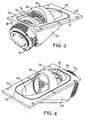
Figures 2 to 6 are various different external views of the pump; and -
Figure 7 is a simplified cross-section illustrating the connection of the assembly to a multi-chambered system. - The
pump 10 comprises ahousing 12 having a bore for receiving acylindrical cartridge 14 containing a pumping mechanism and a plurality offluid inlets fluid outlet 22. - With reference to
Figure 1 , thecartridge 14 comprises amulti-component body 24 within which is mounted adrive shaft 26. Rotation of theshaft 26 is effected by amotor 28 positioned about theshaft 26. Theshaft 26 is mounted on opposite bearings. For example, thedrive shaft 26 may be supported by a hybrid permanent magnet bearing and oil lubricated bearing system. - The pumping mechanism within the cartridge includes at least three
pumping sections first pumping section 30 comprises a set of turbo-molecular stages. In the example shown inFigure 1 , the set of turbo-molecular stages 30 comprises four rotor blades and four stator blades of known angled construction. In this example, the rotor blades of the first pumping section are integral with thedrive shaft 26. - The
second pumping section 32 is similar to thefirst pumping section 30, and also comprises a set of turbo-molecular stages. In the example shown inFigure 1 , the set of turbo-molecular stages 32 also comprises four rotor blades and four stator blades of known angled construction. In this example, the rotor blades of the first pumping section are also integral with thedrive shaft 26. - Downstream of the first and second pumping sections is a
third pumping section 34. Thethird pumping section 34 is in the form of a molecular drag mechanism, for example, a Holweck drag mechanism. In this example, the Holweck mechanism comprises two rotating cylinders and corresponding annular stators having helical channels formed therein in a manner known per se. The rotating cylinders are preferably formed from a carbon fibre material, and are mounted on a disc located on thedrive shaft 26. In this example, the disc is also integral with thedrive shaft 26. Thepump outlet 22 is located downstream from the Holweckmechanism 34. - The
cartridge 14 has threeinlets fluid pressure inlet 16 is located upstream of all of the pumping sections. In this example, thefirst inlet 16 is substantially orthogonal to the longitudinal axis of thedrive shaft 26, as indicated at 36. The second, middlefluid pressure inlet 18 is located interstage thefirst pumping section 30 and thesecond pumping section 32. In this example, thesecond inlet 18 extends about the longitudinal axis of thedrive shaft 26. The third, lowfluid pressure inlet 20 may be located, as illustrated, upstream of or, alternatively, between the stages of the Holweckmechanism 34, such that all of the stages of the Holweck mechanism are in fluid communication with the each of theinlets - Returning now to the
housing 12, the bore has an inlet formed in therear surface 38 of thehousing 12 and through which thecartridge 14 is inserted into thehousing 12. Theinner surfaces cartridge 14 towards the fully inserted position shown inFigures 1 to 6 as it is inserted into the bore. The end of the bore is profiled as indicated at 48 inFigure 1 to define abutment surfaces for engaging the front end of the insertedcartridge 14 and which, with therear surface 38 of thehousing 12, limit the extent to which thecartridge 14 can be inserted into thehousing 12. - As shown in
Figures 1 to 6 , thehousing 12 is shaped so as to expose the bore at a number of locations to allow fluid to enter thefluid inlets cartridge 14 is in the fully inserted position. In the example shown, thehousing 12 comprises amouth 50 formed in a flangedplanar surface 52 of thehousing 12, the flangedplanar surface 52 being inclined at an acute angle to therear surface 38 of the housing, and at an acute angle θ to the longitudinal axis of the bore of the housing. The angle θ may be at any angle between 10° and 80°inclusive, preferably at an angle between 20° and 50° inclusive. In the example illustrated in the figures, θ = 27.5°. In the fully inserted position shown in the figures, thelongitudinal axis 36 of the pumping mechanism is co-axial with the bore of thehousing 12. - In order to locate the cartridge in the fully inserted position, curved
members housing 12 extend across themouth 50 of thehousing 12. In this example, thecurved members housing 12. Alternatively, thecurved members housing 12. The curvedinner surfaces 44, 46 of thecurved members housing 12, form a seal with thebody 24 of thecartridge 14 whilst allowing each of theinlets mouth 50 formed in the flangedplanar surface 52 of thehousing 12. As shown in the figures, part of thefirst inlet 16 and part of thesecond inlet 18 project through themouth 50 of thehousing 12, whilst thethird inlet 20 is located just beneath themouth 50. -
Figure 7 shows thepump 10 attached to an example of amulti-chamber system 60 to be evacuated using thepump 10. In the example shown, themulti-chamber system 60 is a mass spectrometer system. Ahigh vacuum chamber 62 immediately follows first, (depending on the type of system) second, and third evacuatedinterface chambers first interface chamber 64 is the highest-pressure chamber in the evacuated spectrometer system and may contain a capillary or sample cone through which ions are drawn from an ion source into thefirst interface chamber 64. The second,interface chamber 66 may include a first ion guide for guiding ions from thefirst interface chamber 64 into thethird interface chamber 68, and thethird chamber 68 may include a second ion guide for guiding ions from the second interface chamber into thehigh vacuum chamber 62. - The flanged
planar surface 52 of thepump 10 is attached to the planar,bottom surface 70 of thesystem 60, for example by means of bolts or the like. An O-ring located within agroove 72 assists in forming a seal between thesurfaces Figure 7 , with thepump 10 attached to thesystem 60, thecartridge 14 protrudes into thesystem 60 through anopening 74 formed in thebottom surface 70 of the system such that thefirst inlet 16 of thecartridge 14 and thefirst pumping section 30 protrude into thehigh vacuum chamber 62, and thesecond inlet 18 of thecartridge 14 and thesecond pumping section 32 protrude into thethird chamber 68, and such that thepump 10 is inclined at angle θ to the path 76 of ions conveyed within thesystem 60 during use to maximise conductance at the inlets of the pump. The extent to which thepump 10 extends into thesystem 60 is not so great, however, as to cause the pump to cross the ion path 76. To prevent fluid leakage between the chambers of thesystem 60 during use, theupper surface 78 of thecross member 54 sealingly engages a conformingly-profiled lower surface of the dividingwall 80 between thehigh vacuum chamber 60 and thethird chamber 68, and theupper surface 82 of thecross member 56 sealingly engages a conformingly-profiled lower surface of the dividing wall 84 between thesecond chamber 66 and thethird chamber 68. - In use, the
first interface chamber 64 is connected to a backing pump (not shown), which also pumps fluid from theoutlet 22 of thepump 10. The backing pump typically creates a pressure within the first chamber of roughly the same order of magnitude as that at theoutlet 22 of thepump 10. Fluid entering eachinlet pump 10 passes through a respective different number of stages before exiting from the pump. Fluid pumped through thefirst inlet 16 passes through bothsets Holweck mechanism 34 and exits the pump viaoutlet 22. Fluid pumped through thesecond inlet 18 passes through set 32 of turbo-molecular stages and theHolweck mechanism 34 and exits the pump viaoutlet 22. Fluid pumped through thethird inlet 20 passes through theHolweck mechanism 34 only and exits the pump viaoutlet 30. Consequently, thepump 10 is able to provide the required vacuum levels in thechambers chamber 64. In this example, in use thefirst interface chamber 64 is at a pressure of around 1-10 mbar, thesecond interface chamber 66 is at a pressure of around 10-1-1 mbar, thethird interface chamber 68 is at a pressure of around 10-2-10-3 mbar, and thehigh vacuum chamber 60 is at a pressure of around 10-5-10-6 mbar.
Claims (20)
- A system (60) comprising a plurality of pressure chambers (62, 66, 68) and a vacuum pump (10) for differentially evacuating the chambers (62, 66, 68), the pump (10) comprising a plurality of inlets (16, 18, 20) each for receiving fluid from a respective pressure chamber (62, 66, 68) and a pumping mechanism for differentially pumping fluid from the chambers (62, 66, 68), wherein the longitudinal axis (36) of the pump (10) is inclined to the plane of the mouth (50) of an opening (74) into the chambers (62, 66, 68); and characterised in that the pump (10) protrudes through the opening (74) into the chambers (62, 66, 68) such that at least one of the fluid inlets (16, 18, 20) is at least partially located within its respective pressure chamber (62, 66, 68).
- A system (60) according to Claim 1, wherein each of the fluid inlets (16, 18, 20) is at least partially located within its respective pressure chamber (62, 66, 68).
- A system (60) according to Claim 1 or Claim 2, wherein the axis (36) of the pump (10) is inclined at an angle between 10 and 80 degrees inclusive.
- A system (60) according to Claim 3, wherein the axis (36) of the pump (10) is inclined at an angle between 20 and 50 degrees inclusive.
- A system (60) according to any preceding claim, wherein the pump (10) is in the form of a cartridge (14) inserted into a bore configured to expose the fluid inlets (16, 18, 20) of the cartridge (14).
- A system (60) according to Claim 5, wherein the bore protrudes into the chambers (62, 66, 68) through the opening (74), the longitudinal axis (36) of the bore being inclined to the plane of the mouth (50) of the opening (74).
- A system (60) according to Claim 5 or Claim 6, wherein the bore is located in a detachable housing (12).
- A system (60) according to Claim 7, wherein the housing (12) is attachable to a surface (70) defining the mouth (50) of the opening (74).
- A system (60) according to Claim 7 or Claim 8, wherein the housing (12) comprises means (54, 56) for locating the cartridge (14) within the bore.
- A system (60) according to Claim 9, wherein the location means (54, 56) is arranged to form a seal with the outer surface of the cartridge (14).
- A system (60) according to Claim 9 or Claim 10, wherein the location means (54, 56) comprises means for restricting the extent to which the cartridge (14) can be inserted into the bore.
- A system (60) according to any preceding claim, wherein the pumping mechanism comprises a first pumping section (30) and a second pumping section (32) downstream from the first pumping section (30), the sections (30, 32) being arranged such that fluid entering the cartridge (14) through a first inlet (16) passes through the first and second pumping sections (30, 32) towards a fluid outlet, and fluid entering the cartridge (14) through a second inlet (18) passes through, of said sections, only the second section (32) towards the outlet (22).
- A system (60) according to Claim 12, wherein the first inlet (16) is substantially orthogonal to the longitudinal axis (36) of the pump.
- A system (60) according to Claim 12 or Claim 13, wherein the second inlet (18) extends about the longitudinal axis (36) of the pump (10).
- A system (60) according to any of Claims 12 to 14, wherein at least one of the first and the second pumping sections (30, 32) protrudes into a respective pressure chamber (62, 66).
- A system (60) according to any of Claims 12 to 15, wherein at least one of the first and second pumping sections (30, 32) comprises at least one turbo-molecular stage.
- A system (60) according to any of Claims 12 to 16, wherein both of the first and second pumping sections (30, 32) comprise at least one turbo-molecular stage.
- A system (60) according to any of Claims 12 to 17, wherein the cartridge (14) comprises a third inlet (20) and the pumping mechanism comprises a third pumping section (34) downstream from the second pumping section (32), the third pumping section (34) being arranged such that fluid entering the cartridge (14) through the third inlet (20) passes through, of said sections, only the third pumping section (34) towards the pump outlet (22).
- A system (60) according to Claim 18, wherein the third pumping section (34) comprises a multi-stage molecular drag mechanism.
- A system (60) according to Claim 19, wherein the molecular drag mechanism is a multi-stage Holweck mechanism with a plurality of channels arranged as a plurality of helixes.
Priority Applications (1)
| Application Number | Priority Date | Filing Date | Title |
|---|---|---|---|
| EP10175459A EP2273128B1 (en) | 2004-06-25 | 2005-06-09 | Vacuum pump |
Applications Claiming Priority (2)
| Application Number | Priority Date | Filing Date | Title |
|---|---|---|---|
| GBGB0414316.0A GB0414316D0 (en) | 2004-06-25 | 2004-06-25 | Vacuum pump |
| PCT/GB2005/002249 WO2006000745A1 (en) | 2004-06-25 | 2005-06-09 | Vaccum pump |
Related Child Applications (2)
| Application Number | Title | Priority Date | Filing Date |
|---|---|---|---|
| EP10175459A Division-Into EP2273128B1 (en) | 2004-06-25 | 2005-06-09 | Vacuum pump |
| EP10175459.6 Division-Into | 2010-09-06 |
Publications (3)
| Publication Number | Publication Date |
|---|---|
| EP1759118A1 EP1759118A1 (en) | 2007-03-07 |
| EP1759118B1 EP1759118B1 (en) | 2011-04-27 |
| EP1759118B2 true EP1759118B2 (en) | 2016-10-05 |
Family
ID=32800225
Family Applications (2)
| Application Number | Title | Priority Date | Filing Date |
|---|---|---|---|
| EP10175459A Not-in-force EP2273128B1 (en) | 2004-06-25 | 2005-06-09 | Vacuum pump |
| EP05748158.2A Active EP1759118B2 (en) | 2004-06-25 | 2005-06-09 | Vacuum pump |
Family Applications Before (1)
| Application Number | Title | Priority Date | Filing Date |
|---|---|---|---|
| EP10175459A Not-in-force EP2273128B1 (en) | 2004-06-25 | 2005-06-09 | Vacuum pump |
Country Status (9)
| Country | Link |
|---|---|
| US (2) | US7811065B2 (en) |
| EP (2) | EP2273128B1 (en) |
| JP (1) | JP2008504479A (en) |
| CN (2) | CN1973135B (en) |
| AT (2) | ATE544952T1 (en) |
| CA (2) | CA2780091C (en) |
| DE (1) | DE602005027695D1 (en) |
| GB (1) | GB0414316D0 (en) |
| WO (1) | WO2006000745A1 (en) |
Cited By (1)
| Publication number | Priority date | Publication date | Assignee | Title |
|---|---|---|---|---|
| EP2886870B1 (en) | 2013-12-18 | 2017-12-20 | Pfeiffer Vacuum GmbH | Vacuum pump with improved inlet geometry |
Families Citing this family (20)
| Publication number | Priority date | Publication date | Assignee | Title |
|---|---|---|---|---|
| GB0414316D0 (en) * | 2004-06-25 | 2004-07-28 | Boc Group Plc | Vacuum pump |
| US20120027583A1 (en) * | 2006-05-04 | 2012-02-02 | Bernd Hofmann | Vacuum pump |
| DE102006020710A1 (en) * | 2006-05-04 | 2007-11-08 | Pfeiffer Vacuum Gmbh | Vacuum pump with housing |
| US8288719B1 (en) * | 2006-12-29 | 2012-10-16 | Griffin Analytical Technologies, Llc | Analytical instruments, assemblies, and methods |
| DE102007010068A1 (en) | 2007-02-28 | 2008-09-04 | Thermo Fisher Scientific (Bremen) Gmbh | Vacuum pump or vacuum device for evacuation of multiple volumes, has two suction inlets with multiple pressure stages and outer suction inlet for one pressure stage spatially encompasses inner suction inlet for another pressure stage |
| DE102007027354A1 (en) * | 2007-06-11 | 2008-12-18 | Oerlikon Leybold Vacuum Gmbh | Turbo molecular pump |
| GB2466156B8 (en) * | 2007-09-07 | 2015-10-14 | Ionics Mass Spectrometry Group | Multi-pressure stage mass spectrometer and methods |
| DE102007044945A1 (en) * | 2007-09-20 | 2009-04-09 | Pfeiffer Vacuum Gmbh | vacuum pump |
| JP5244730B2 (en) * | 2009-07-31 | 2013-07-24 | 株式会社日立ハイテクノロジーズ | Low vacuum scanning electron microscope |
| GB2473839B (en) * | 2009-09-24 | 2016-06-01 | Edwards Ltd | Mass spectrometer |
| GB2489975A (en) * | 2011-04-14 | 2012-10-17 | Edwards Ltd | Vacuum pumping system |
| US8481923B1 (en) * | 2012-06-29 | 2013-07-09 | Agilent Technologies, Inc. | Atmospheric pressure plasma mass spectrometer |
| DE202013003855U1 (en) * | 2013-04-25 | 2014-07-28 | Oerlikon Leybold Vacuum Gmbh | Examination device and multi-inlet vacuum pump |
| GB2516969B (en) | 2013-08-09 | 2017-04-19 | Edwards Ltd | Vacuum system securing devices |
| DE102013222167A1 (en) * | 2013-10-31 | 2015-04-30 | Pfeiffer Vacuum Gmbh | vacuum pump |
| GB2538962B (en) * | 2015-06-01 | 2019-06-26 | Edwards Ltd | Vacuum pump |
| CN106340437B (en) * | 2015-07-09 | 2019-03-22 | 株式会社岛津制作所 | The method of the reduction losses of ions and rear class vacuum loading of mass spectrograph and its application |
| DE102018119747B3 (en) * | 2018-08-14 | 2020-02-13 | Bruker Daltonik Gmbh | TURBOMOLECULAR PUMP FOR MASS SPECTROMETERS |
| JP7196763B2 (en) * | 2018-10-25 | 2022-12-27 | 株式会社島津製作所 | turbomolecular pump and mass spectrometer |
| GB2601515B (en) * | 2020-12-02 | 2022-12-28 | Agilent Technologies Inc | Vacuum pump with elastic spacer |
Family Cites Families (15)
| Publication number | Priority date | Publication date | Assignee | Title |
|---|---|---|---|---|
| US5162650A (en) | 1991-01-25 | 1992-11-10 | Finnigan Corporation | Method and apparatus for multi-stage particle separation with gas addition for a mass spectrometer |
| EP0603694A1 (en) | 1992-12-24 | 1994-06-29 | BALZERS-PFEIFFER GmbH | Vacuum system |
| US5733104A (en) * | 1992-12-24 | 1998-03-31 | Balzers-Pfeiffer Gmbh | Vacuum pump system |
| DE4326265A1 (en) | 1993-08-05 | 1995-02-09 | Leybold Ag | Test gas detector, preferably for leak detection devices, and method for operating a test gas detector of this type |
| DE19508566A1 (en) * | 1995-03-10 | 1996-09-12 | Balzers Pfeiffer Gmbh | Molecular vacuum pump with cooling gas device and method for its operation |
| GB9725146D0 (en) | 1997-11-27 | 1998-01-28 | Boc Group Plc | Improvements in vacuum pumps |
| DE19821634A1 (en) | 1998-05-14 | 1999-11-18 | Leybold Vakuum Gmbh | Friction vacuum pump with staged rotor and stator |
| EP1090231B2 (en) * | 1998-05-26 | 2015-07-08 | Oerlikon Leybold Vacuum GmbH | Frictional vacuum pump with chassis, rotor, housing and device fitted with such a frictional vacuum pump |
| DE19901340B4 (en) | 1998-05-26 | 2016-03-24 | Leybold Vakuum Gmbh | Friction vacuum pump with chassis, rotor and housing and device equipped with a friction vacuum pump of this type |
| GB9921983D0 (en) * | 1999-09-16 | 1999-11-17 | Boc Group Plc | Improvements in vacuum pumps |
| DE10008691B4 (en) | 2000-02-24 | 2017-10-26 | Pfeiffer Vacuum Gmbh | Gas friction pump |
| GB2360066A (en) | 2000-03-06 | 2001-09-12 | Boc Group Plc | Vacuum pump |
| DE10055057A1 (en) | 2000-11-07 | 2002-05-08 | Pfeiffer Vacuum Gmbh | Leak detector pump has high vacuum pump, gas analyzer, test object connector, gas outlet opening, gas inlet opening, valve bodies and gas connections in or forming parts of housing |
| GB0124731D0 (en) * | 2001-10-15 | 2001-12-05 | Boc Group Plc | Vacuum pumps |
| GB0414316D0 (en) * | 2004-06-25 | 2004-07-28 | Boc Group Plc | Vacuum pump |
-
2004
- 2004-06-25 GB GBGB0414316.0A patent/GB0414316D0/en not_active Ceased
-
2005
- 2005-06-09 US US11/630,729 patent/US7811065B2/en active Active
- 2005-06-09 EP EP10175459A patent/EP2273128B1/en not_active Not-in-force
- 2005-06-09 CA CA2780091A patent/CA2780091C/en not_active Expired - Fee Related
- 2005-06-09 AT AT10175459T patent/ATE544952T1/en active
- 2005-06-09 CN CN200580021217XA patent/CN1973135B/en active Active
- 2005-06-09 CA CA2565325A patent/CA2565325C/en not_active Expired - Fee Related
- 2005-06-09 WO PCT/GB2005/002249 patent/WO2006000745A1/en not_active Application Discontinuation
- 2005-06-09 JP JP2007517437A patent/JP2008504479A/en active Pending
- 2005-06-09 EP EP05748158.2A patent/EP1759118B2/en active Active
- 2005-06-09 DE DE602005027695T patent/DE602005027695D1/en active Active
- 2005-06-09 AT AT05748158T patent/ATE507394T1/en not_active IP Right Cessation
- 2005-06-09 CN CN200910208870A patent/CN101705945A/en active Pending
-
2010
- 2010-09-09 US US12/878,592 patent/US8757987B2/en active Active
Cited By (1)
| Publication number | Priority date | Publication date | Assignee | Title |
|---|---|---|---|---|
| EP2886870B1 (en) | 2013-12-18 | 2017-12-20 | Pfeiffer Vacuum GmbH | Vacuum pump with improved inlet geometry |
Also Published As
| Publication number | Publication date |
|---|---|
| US20110142686A1 (en) | 2011-06-16 |
| WO2006000745A1 (en) | 2006-01-05 |
| US20080166219A1 (en) | 2008-07-10 |
| CA2780091C (en) | 2013-07-30 |
| ATE544952T1 (en) | 2012-02-15 |
| US8757987B2 (en) | 2014-06-24 |
| CN101705945A (en) | 2010-05-12 |
| CN1973135B (en) | 2010-05-05 |
| ATE507394T1 (en) | 2011-05-15 |
| EP1759118B1 (en) | 2011-04-27 |
| GB0414316D0 (en) | 2004-07-28 |
| CN1973135A (en) | 2007-05-30 |
| CA2780091A1 (en) | 2006-01-05 |
| US7811065B2 (en) | 2010-10-12 |
| DE602005027695D1 (en) | 2011-06-09 |
| CA2565325C (en) | 2013-05-28 |
| CA2565325A1 (en) | 2006-01-05 |
| EP2273128A1 (en) | 2011-01-12 |
| JP2008504479A (en) | 2008-02-14 |
| EP1759118A1 (en) | 2007-03-07 |
| EP2273128B1 (en) | 2012-02-08 |
Similar Documents
| Publication | Publication Date | Title |
|---|---|---|
| EP1759118B1 (en) | Vacuum pump | |
| US8235678B2 (en) | Multi-stage vacuum pumping arrangement | |
| US7866940B2 (en) | Vacuum pump | |
| US7850434B2 (en) | Pumping arrangement | |
| JP4340431B2 (en) | Vacuum pump | |
| US8206081B2 (en) | Vacuum pump | |
| US7762763B2 (en) | Vacuum pump | |
| US20180163732A1 (en) | Vacuum pump | |
| EP1085214B1 (en) | Vacuum pumps | |
| JP6225213B2 (en) | Vacuum pump |
Legal Events
| Date | Code | Title | Description |
|---|---|---|---|
| PUAI | Public reference made under article 153(3) epc to a published international application that has entered the european phase |
Free format text: ORIGINAL CODE: 0009012 |
|
| 17P | Request for examination filed |
Effective date: 20061020 |
|
| AK | Designated contracting states |
Kind code of ref document: A1 Designated state(s): AT BE BG CH CY CZ DE DK EE ES FI FR GB GR HU IE IS IT LI LT LU MC NL PL PT RO SE SI SK TR |
|
| RAP1 | Party data changed (applicant data changed or rights of an application transferred) |
Owner name: EDWARDS LIMITED |
|
| DAX | Request for extension of the european patent (deleted) | ||
| 17Q | First examination report despatched |
Effective date: 20071031 |
|
| GRAP | Despatch of communication of intention to grant a patent |
Free format text: ORIGINAL CODE: EPIDOSNIGR1 |
|
| RTI1 | Title (correction) |
Free format text: VACUUM PUMP |
|
| GRAS | Grant fee paid |
Free format text: ORIGINAL CODE: EPIDOSNIGR3 |
|
| GRAA | (expected) grant |
Free format text: ORIGINAL CODE: 0009210 |
|
| REG | Reference to a national code |
Ref country code: DE Ref legal event code: R081 Ref document number: 602005027695 Country of ref document: DE Owner name: EDWARDS LTD., BURGESS HILL, GB Free format text: FORMER OWNER: THE BOC GROUP PLC, WINDLESHAM, SURREY, GB |
|
| AK | Designated contracting states |
Kind code of ref document: B1 Designated state(s): AT BE BG CH CY CZ DE DK EE ES FI FR GB GR HU IE IS IT LI LT LU MC NL PL PT RO SE SI SK TR |
|
| REG | Reference to a national code |
Ref country code: GB Ref legal event code: FG4D |
|
| REG | Reference to a national code |
Ref country code: CH Ref legal event code: EP |
|
| REG | Reference to a national code |
Ref country code: IE Ref legal event code: FG4D |
|
| REF | Corresponds to: |
Ref document number: 602005027695 Country of ref document: DE Date of ref document: 20110609 Kind code of ref document: P |
|
| REG | Reference to a national code |
Ref country code: DE Ref legal event code: R096 Ref document number: 602005027695 Country of ref document: DE Effective date: 20110609 |
|
| REG | Reference to a national code |
Ref country code: NL Ref legal event code: VDEP Effective date: 20110427 |
|
| LTIE | Lt: invalidation of european patent or patent extension |
Effective date: 20110427 |
|
| PG25 | Lapsed in a contracting state [announced via postgrant information from national office to epo] |
Ref country code: LT Free format text: LAPSE BECAUSE OF FAILURE TO SUBMIT A TRANSLATION OF THE DESCRIPTION OR TO PAY THE FEE WITHIN THE PRESCRIBED TIME-LIMIT Effective date: 20110427 Ref country code: SE Free format text: LAPSE BECAUSE OF FAILURE TO SUBMIT A TRANSLATION OF THE DESCRIPTION OR TO PAY THE FEE WITHIN THE PRESCRIBED TIME-LIMIT Effective date: 20110427 Ref country code: PT Free format text: LAPSE BECAUSE OF FAILURE TO SUBMIT A TRANSLATION OF THE DESCRIPTION OR TO PAY THE FEE WITHIN THE PRESCRIBED TIME-LIMIT Effective date: 20110829 |
|
| PG25 | Lapsed in a contracting state [announced via postgrant information from national office to epo] |
Ref country code: CY Free format text: LAPSE BECAUSE OF FAILURE TO SUBMIT A TRANSLATION OF THE DESCRIPTION OR TO PAY THE FEE WITHIN THE PRESCRIBED TIME-LIMIT Effective date: 20110427 Ref country code: BE Free format text: LAPSE BECAUSE OF FAILURE TO SUBMIT A TRANSLATION OF THE DESCRIPTION OR TO PAY THE FEE WITHIN THE PRESCRIBED TIME-LIMIT Effective date: 20110427 Ref country code: FI Free format text: LAPSE BECAUSE OF FAILURE TO SUBMIT A TRANSLATION OF THE DESCRIPTION OR TO PAY THE FEE WITHIN THE PRESCRIBED TIME-LIMIT Effective date: 20110427 Ref country code: AT Free format text: LAPSE BECAUSE OF FAILURE TO SUBMIT A TRANSLATION OF THE DESCRIPTION OR TO PAY THE FEE WITHIN THE PRESCRIBED TIME-LIMIT Effective date: 20110427 Ref country code: SI Free format text: LAPSE BECAUSE OF FAILURE TO SUBMIT A TRANSLATION OF THE DESCRIPTION OR TO PAY THE FEE WITHIN THE PRESCRIBED TIME-LIMIT Effective date: 20110427 Ref country code: ES Free format text: LAPSE BECAUSE OF FAILURE TO SUBMIT A TRANSLATION OF THE DESCRIPTION OR TO PAY THE FEE WITHIN THE PRESCRIBED TIME-LIMIT Effective date: 20110807 Ref country code: IS Free format text: LAPSE BECAUSE OF FAILURE TO SUBMIT A TRANSLATION OF THE DESCRIPTION OR TO PAY THE FEE WITHIN THE PRESCRIBED TIME-LIMIT Effective date: 20110827 Ref country code: GR Free format text: LAPSE BECAUSE OF FAILURE TO SUBMIT A TRANSLATION OF THE DESCRIPTION OR TO PAY THE FEE WITHIN THE PRESCRIBED TIME-LIMIT Effective date: 20110728 |
|
| PG25 | Lapsed in a contracting state [announced via postgrant information from national office to epo] |
Ref country code: NL Free format text: LAPSE BECAUSE OF FAILURE TO SUBMIT A TRANSLATION OF THE DESCRIPTION OR TO PAY THE FEE WITHIN THE PRESCRIBED TIME-LIMIT Effective date: 20110427 |
|
| PLBI | Opposition filed |
Free format text: ORIGINAL CODE: 0009260 |
|
| PG25 | Lapsed in a contracting state [announced via postgrant information from national office to epo] |
Ref country code: CZ Free format text: LAPSE BECAUSE OF FAILURE TO SUBMIT A TRANSLATION OF THE DESCRIPTION OR TO PAY THE FEE WITHIN THE PRESCRIBED TIME-LIMIT Effective date: 20110427 Ref country code: EE Free format text: LAPSE BECAUSE OF FAILURE TO SUBMIT A TRANSLATION OF THE DESCRIPTION OR TO PAY THE FEE WITHIN THE PRESCRIBED TIME-LIMIT Effective date: 20110427 |
|
| REG | Reference to a national code |
Ref country code: CH Ref legal event code: PL |
|
| 26 | Opposition filed |
Opponent name: OERLIKON LEYBOLD VACUUM GMBH Effective date: 20120124 |
|
| PG25 | Lapsed in a contracting state [announced via postgrant information from national office to epo] |
Ref country code: SK Free format text: LAPSE BECAUSE OF FAILURE TO SUBMIT A TRANSLATION OF THE DESCRIPTION OR TO PAY THE FEE WITHIN THE PRESCRIBED TIME-LIMIT Effective date: 20110427 Ref country code: PL Free format text: LAPSE BECAUSE OF FAILURE TO SUBMIT A TRANSLATION OF THE DESCRIPTION OR TO PAY THE FEE WITHIN THE PRESCRIBED TIME-LIMIT Effective date: 20110427 |
|
| PLAX | Notice of opposition and request to file observation + time limit sent |
Free format text: ORIGINAL CODE: EPIDOSNOBS2 |
|
| REG | Reference to a national code |
Ref country code: IE Ref legal event code: MM4A |
|
| REG | Reference to a national code |
Ref country code: DE Ref legal event code: R026 Ref document number: 602005027695 Country of ref document: DE Effective date: 20120124 |
|
| PG25 | Lapsed in a contracting state [announced via postgrant information from national office to epo] |
Ref country code: LI Free format text: LAPSE BECAUSE OF NON-PAYMENT OF DUE FEES Effective date: 20110630 Ref country code: IE Free format text: LAPSE BECAUSE OF NON-PAYMENT OF DUE FEES Effective date: 20110609 Ref country code: CH Free format text: LAPSE BECAUSE OF NON-PAYMENT OF DUE FEES Effective date: 20110630 |
|
| PLAF | Information modified related to communication of a notice of opposition and request to file observations + time limit |
Free format text: ORIGINAL CODE: EPIDOSCOBS2 |
|
| PLBB | Reply of patent proprietor to notice(s) of opposition received |
Free format text: ORIGINAL CODE: EPIDOSNOBS3 |
|
| PG25 | Lapsed in a contracting state [announced via postgrant information from national office to epo] |
Ref country code: MC Free format text: LAPSE BECAUSE OF NON-PAYMENT OF DUE FEES Effective date: 20110630 |
|
| PG25 | Lapsed in a contracting state [announced via postgrant information from national office to epo] |
Ref country code: LU Free format text: LAPSE BECAUSE OF NON-PAYMENT OF DUE FEES Effective date: 20110609 |
|
| PG25 | Lapsed in a contracting state [announced via postgrant information from national office to epo] |
Ref country code: BG Free format text: LAPSE BECAUSE OF FAILURE TO SUBMIT A TRANSLATION OF THE DESCRIPTION OR TO PAY THE FEE WITHIN THE PRESCRIBED TIME-LIMIT Effective date: 20110727 |
|
| PG25 | Lapsed in a contracting state [announced via postgrant information from national office to epo] |
Ref country code: TR Free format text: LAPSE BECAUSE OF FAILURE TO SUBMIT A TRANSLATION OF THE DESCRIPTION OR TO PAY THE FEE WITHIN THE PRESCRIBED TIME-LIMIT Effective date: 20110427 |
|
| PG25 | Lapsed in a contracting state [announced via postgrant information from national office to epo] |
Ref country code: HU Free format text: LAPSE BECAUSE OF FAILURE TO SUBMIT A TRANSLATION OF THE DESCRIPTION OR TO PAY THE FEE WITHIN THE PRESCRIBED TIME-LIMIT Effective date: 20110427 |
|
| RIC2 | Information provided on ipc code assigned after grant |
Ipc: F04D 19/04 20060101AFI20150623BHEP Ipc: H01J 49/24 20060101ALI20150623BHEP Ipc: G01M 3/20 20060101ALI20150623BHEP Ipc: F04D 29/60 20060101ALI20150623BHEP |
|
| APBM | Appeal reference recorded |
Free format text: ORIGINAL CODE: EPIDOSNREFNO |
|
| APBP | Date of receipt of notice of appeal recorded |
Free format text: ORIGINAL CODE: EPIDOSNNOA2O |
|
| APAH | Appeal reference modified |
Free format text: ORIGINAL CODE: EPIDOSCREFNO |
|
| APBU | Appeal procedure closed |
Free format text: ORIGINAL CODE: EPIDOSNNOA9O |
|
| REG | Reference to a national code |
Ref country code: FR Ref legal event code: PLFP Year of fee payment: 12 |
|
| PUAH | Patent maintained in amended form |
Free format text: ORIGINAL CODE: 0009272 |
|
| STAA | Information on the status of an ep patent application or granted ep patent |
Free format text: STATUS: PATENT MAINTAINED AS AMENDED |
|
| 27A | Patent maintained in amended form |
Effective date: 20161005 |
|
| AK | Designated contracting states |
Kind code of ref document: B2 Designated state(s): AT BE BG CH CY CZ DE DK EE ES FI FR GB GR HU IE IS IT LI LT LU MC NL PL PT RO SE SI SK TR |
|
| REG | Reference to a national code |
Ref country code: DE Ref legal event code: R102 Ref document number: 602005027695 Country of ref document: DE |
|
| REG | Reference to a national code |
Ref country code: FR Ref legal event code: PLFP Year of fee payment: 13 |
|
| REG | Reference to a national code |
Ref country code: FR Ref legal event code: PLFP Year of fee payment: 14 |
|
| REG | Reference to a national code |
Ref country code: DE Ref legal event code: R082 Ref document number: 602005027695 Country of ref document: DE Representative=s name: FLEUCHAUS & GALLO PARTNERSCHAFT MBB PATENTANWA, DE Ref country code: DE Ref legal event code: R082 Ref document number: 602005027695 Country of ref document: DE Representative=s name: FLEUCHAUS & GALLO PARTNERSCHAFT MBB, DE Ref country code: DE Ref legal event code: R081 Ref document number: 602005027695 Country of ref document: DE Owner name: EDWARDS LTD., BURGESS HILL, GB Free format text: FORMER OWNER: EDWARDS LTD., CRAWLEY, WEST SUSSEX, GB |
|
| REG | Reference to a national code |
Ref country code: FR Ref legal event code: CA Effective date: 20180906 |
|
| PGFP | Annual fee paid to national office [announced via postgrant information from national office to epo] |
Ref country code: IT Payment date: 20190621 Year of fee payment: 15 |
|
| PGFP | Annual fee paid to national office [announced via postgrant information from national office to epo] |
Ref country code: FR Payment date: 20190625 Year of fee payment: 15 |
|
| PGFP | Annual fee paid to national office [announced via postgrant information from national office to epo] |
Ref country code: GB Payment date: 20190627 Year of fee payment: 15 |
|
| GBPC | Gb: european patent ceased through non-payment of renewal fee |
Effective date: 20200609 |
|
| PG25 | Lapsed in a contracting state [announced via postgrant information from national office to epo] |
Ref country code: GB Free format text: LAPSE BECAUSE OF NON-PAYMENT OF DUE FEES Effective date: 20200609 Ref country code: FR Free format text: LAPSE BECAUSE OF NON-PAYMENT OF DUE FEES Effective date: 20200630 |
|
| PG25 | Lapsed in a contracting state [announced via postgrant information from national office to epo] |
Ref country code: IT Free format text: LAPSE BECAUSE OF NON-PAYMENT OF DUE FEES Effective date: 20200609 |
|
| PGFP | Annual fee paid to national office [announced via postgrant information from national office to epo] |
Ref country code: DE Payment date: 20220629 Year of fee payment: 18 |
|
| REG | Reference to a national code |
Ref country code: DE Ref legal event code: R082 Ref document number: 602005027695 Country of ref document: DE Representative=s name: FLEUCHAUS & GALLO PARTNERSCHAFT MBB - PATENT- , DE Ref country code: DE Ref legal event code: R082 Ref document number: 602005027695 Country of ref document: DE Representative=s name: FLEUCHAUS & GALLO PARTNERSCHAFT MBB PATENTANWA, DE |
|
| P01 | Opt-out of the competence of the unified patent court (upc) registered |
Effective date: 20230425 |
|
| REG | Reference to a national code |
Ref country code: DE Ref legal event code: R119 Ref document number: 602005027695 Country of ref document: DE |