EP1758703B1 - Outil d'usinage de pieces par enlevement de copeaux - Google Patents
Outil d'usinage de pieces par enlevement de copeaux Download PDFInfo
- Publication number
- EP1758703B1 EP1758703B1 EP05734878.1A EP05734878A EP1758703B1 EP 1758703 B1 EP1758703 B1 EP 1758703B1 EP 05734878 A EP05734878 A EP 05734878A EP 1758703 B1 EP1758703 B1 EP 1758703B1
- Authority
- EP
- European Patent Office
- Prior art keywords
- tool
- tool body
- screwing devices
- insert
- cartridge
- Prior art date
- Legal status (The legal status is an assumption and is not a legal conclusion. Google has not performed a legal analysis and makes no representation as to the accuracy of the status listed.)
- Not-in-force
Links
- 238000003754 machining Methods 0.000 title claims description 11
- 238000005520 cutting process Methods 0.000 claims description 19
- 230000000284 resting effect Effects 0.000 claims 1
- 238000004873 anchoring Methods 0.000 description 7
- 238000003801 milling Methods 0.000 description 7
- 238000006073 displacement reaction Methods 0.000 description 5
- 230000001419 dependent effect Effects 0.000 description 2
- 239000000463 material Substances 0.000 description 2
- 230000002411 adverse Effects 0.000 description 1
- 230000005540 biological transmission Effects 0.000 description 1
- 239000003795 chemical substances by application Substances 0.000 description 1
- 150000001875 compounds Chemical class 0.000 description 1
- 229910003460 diamond Inorganic materials 0.000 description 1
- 239000010432 diamond Substances 0.000 description 1
- 238000009826 distribution Methods 0.000 description 1
- 230000000694 effects Effects 0.000 description 1
- 230000002349 favourable effect Effects 0.000 description 1
- 238000003780 insertion Methods 0.000 description 1
- 230000037431 insertion Effects 0.000 description 1
- 238000009434 installation Methods 0.000 description 1
- 238000004519 manufacturing process Methods 0.000 description 1
- 238000000034 method Methods 0.000 description 1
Images

Classifications
-
- B—PERFORMING OPERATIONS; TRANSPORTING
- B23—MACHINE TOOLS; METAL-WORKING NOT OTHERWISE PROVIDED FOR
- B23C—MILLING
- B23C5/00—Milling-cutters
- B23C5/16—Milling-cutters characterised by physical features other than shape
- B23C5/20—Milling-cutters characterised by physical features other than shape with removable cutter bits or teeth or cutting inserts
- B23C5/22—Securing arrangements for bits or teeth or cutting inserts
- B23C5/2204—Securing arrangements for bits or teeth or cutting inserts with cutting inserts clamped against the walls of the recess in the cutter body by a clamping member acting upon the wall of a hole in the insert
- B23C5/2226—Securing arrangements for bits or teeth or cutting inserts with cutting inserts clamped against the walls of the recess in the cutter body by a clamping member acting upon the wall of a hole in the insert for plate-like cutting inserts fitted on an intermediate carrier, e.g. shank fixed in the cutter body
-
- B—PERFORMING OPERATIONS; TRANSPORTING
- B23—MACHINE TOOLS; METAL-WORKING NOT OTHERWISE PROVIDED FOR
- B23C—MILLING
- B23C2240/00—Details of connections of tools or workpieces
- B23C2240/24—Connections using screws
-
- Y—GENERAL TAGGING OF NEW TECHNOLOGICAL DEVELOPMENTS; GENERAL TAGGING OF CROSS-SECTIONAL TECHNOLOGIES SPANNING OVER SEVERAL SECTIONS OF THE IPC; TECHNICAL SUBJECTS COVERED BY FORMER USPC CROSS-REFERENCE ART COLLECTIONS [XRACs] AND DIGESTS
- Y10—TECHNICAL SUBJECTS COVERED BY FORMER USPC
- Y10T—TECHNICAL SUBJECTS COVERED BY FORMER US CLASSIFICATION
- Y10T407/00—Cutters, for shaping
- Y10T407/19—Rotary cutting tool
- Y10T407/1906—Rotary cutting tool including holder [i.e., head] having seat for inserted tool
- Y10T407/1932—Rotary cutting tool including holder [i.e., head] having seat for inserted tool with means to fasten tool seat to holder
Definitions
- the present invention relates to a tool for the chip-removing machining of workpieces according to the preamble of claim 1.
- a tool is for example off DE 1143082 known.
- Tools for chip removal machining of workpieces are regularly equipped with distributed on its circumference arranged cutting means.
- the cutting means are often inserts made of PCD (polycrystalline diamond), carbide or the like, which are attached to cassettes, which in turn are arranged in recesses on the milling head.
- the stresses in the compounds occur on the one hand by high feed speeds and tough or hard material to be machined, and on the other hand by the high speeds of the tools. For example, at a speed of 30,000 rpm, only centrifugal force, already a load of about one ton on the connection between a cutting agent cartridge and the tool body.
- the object of the present invention is to increase the reliability and machining accuracy for a tool of the type mentioned.
- the invention is based on a tool for chip-removing machining of workpieces.
- the tool comprises a tool main body which rotates during workpiece machining, with cassettes which have cutting means and are fastened by means of screw means to the tool main body.
- the screw means are based on an abutment surface having anchoring means on the tool body.
- the tool is characterized in that the anchoring means of the screw means are arranged radially inwardly with respect to the position of the cassette.
- the screw means are arranged radially on the tool body.
- the anchoring means of the screw means are arranged radially inwardly with respect to the position of the cassette.
- anchoring means which have a head-like thickened area specially adapted to the contact area of the tool body.
- the head-like thickened region of the screw means does not necessarily have to have a cylindrical shape, it may for example be formed as a curved plate, the support area, for example, the radius of an axially parallel recess in the tool body is shaped accordingly.
- the support area for example, the radius of an axially parallel recess in the tool body is shaped accordingly.
- bayonet-type connections or the like are also conceivable.
- screw means can be formed in the radial direction implementations in the tool body, which are holes in the simplest case.
- the radially aligned bushings for the screw means may be formed as axially extending, open slots, which advantageously allow a front-side insertion of the screw in the axial direction in the tool body. This can be made possible at the same time an axial positioning of the cutting body.
- the slit-like passages in the tool body for the screw means are advantageously designed so that occurring during operation of the tool tilting moments do not adversely affect the positioning of the cutting means. For example, this can be achieved by a sufficiently long slot, or by depressions in the tool body, in which the head-like thickened portion of the screw can be sunk. It is also conceivable according to large-scale trained support areas that ensure sufficient support against occurring tilting moments.
- the threaded portion of the screw means may directly engage and co-operate with a thread disposed on a cartridge. But it is also conceivable that acts on the thread another screw, such as, for example, in the case of an external thread, a nut, or another screw with a further support area which counteracts the first edition area and fixed the cassette to the tool body. This may for example be the case when the screw means has an internal thread.
- a recess may be provided on the cassette, which allows access for the operation of the screw means, so that this is embedded in the cassette, without protruding therefrom.
- the cassettes comprise at least two parts, wherein the at least two cassette parts in each case in a displacement surface, preferably a sliding plane against each other are displaceable, and by screw means are attached to the tool body so that when tightened screw a force component acts on the at least two parts that occur in the sliding surface on the two cassette parts opposite effective force components.
- the tensioning means can be designed, for example, as a wedge means which, under the action of the screw means, move relative to one another via their wedge surfaces located in the displacement surface and press against the wall of the recess.
- a stop surface is provided for this purpose on at least one cassette part, which bears in the tensioned state of the clamping means on a wall of a recess formed in the tool base body for the respective cassette.
- the cutting means are arranged on this at least one cassette part. This results in the advantage that the cutting means can be positioned accurately and clearly in the circumferential direction.
- the head of the screw means can basically be arranged radially outside or inside.
- the cross-section of the recesses for the cassettes may taper in a radially outward direction. This results in a further wedge shape, wherein the tip of this wedge is aligned radially outwardly in the body, so that centrifugal forces occurring wedging the cassette in the tool body result and the wedge elements always rest against the side walls of their associated recesses.
- the screw means have a spring action, in particular in its axial extension, the longitudinal extent of which is predeterminable as a function of the rotational speed-dependent centrifugal forces.
- the positioning of the cutting means can take place taking into account the length expansion of the screw means occurring at the intended operating speed.
- the cassettes carrying the cutting means can be pretensioned during installation of the tool to the extent that they provide the correct machining dimensions for workpiece machining at the speed provided for the application area.
- the tool 1 comprises a tool base body 2, in which a cassette 3 having a cutting means is arranged in a cassette receptacle 4 provided for its reception and fixed with a screw means 5.
- the basic tool body 2 consists of a radially outwardly arranged tool body part 2A, are formed on the cartridge holders 4 for the cassettes 3, and from a radially inwardly disposed, the second tool body part 2B, on which the illustrated screw means 5 with his supported on the anchoring means 6 bearing surface 6A in the tightened state of the screw is supported.
- the bearing surface is formed on the head-like thickened portion 7 of the screw 5 and facing the body part 2B.
- the screw means 5 can be rotated about the screw axis 8 in the two directions of rotation indicated by the arrow 9 for fixing or for releasing the cassette 3.
- the rotation of the screw 5 is carried out in the tool body 2 arranged in the recess 10, and can be introduced via an actuating means, in this case a hexagon socket 11.
- the hexagon socket shown as an example may optionally be arranged on the screwing-end face in the radially inner and / or in the radially outer region of the tool body.
- the thread 12 is tightened or released accordingly.
- an external thread and on the cassette part 3A of the cassette 3, a corresponding internal thread are formed on the screw means 5.
- the cassette part 3A When tightening the thread 12, the cassette part 3A, based on the tool body 2, in the direction of the arrow 13 pulled radially inward. In this case, it presses against the second cassette part 3B at the displacement plane 14 at an angle which is between 90 ° and 180 ° with respect to the screw axis 8. This angle results in an inclined support surface, in which the displacement plane 14 is located, and along which the two cassette parts 3A, 3B are moved under the fixing effect of the screw 5 against each other so that they, with their, approximately perpendicular to the plane, the side walls of the Cassette recording 4 facing outer surfaces are pressed against the corresponding inner surfaces of the cartridge holders 4.
- the direction of movement of the cassette part 3A in fixing the cassette 3 is represented by the arrow 15, and the direction of movement of the cassette part 3B by the arrow 16.
- the screw 5 can be performed in this embodiment radially from the inside through the recess 10 in the tool body 2 to the outside. It penetrates with its threaded part after passing through the tool body part 2B and the bottom portion of the tool body part 2A in the cassette holder 4 a. Subsequently, it is guided by the recess 10 also formed in the cassette part 3B radially outward, and finally engages in the external thread of the cassette part 3A so far and long, until the fixing process described above is completed.
- Modified embodiments of this erffenage can be realized for example by a slot-shaped recess 10, wherein the slot at the end of the tool, such as a milling head, opens so that the screw means, optionally together with the two cassette parts 3A, 3B from the front side in the Milling head can be inserted.
- the slot as round encircling closed opening is formed, so that access to the recess 10 only radially from the outside or from the inside is possible.
- the head 7 of the screw means 5 may be elongated in such an embodiment, wherein the two longitudinal sides are so close to each other that the head 7 can be inserted from the outside through the slot-shaped recess 10 in the tool body 2. After the head 7 has arrived in a hollow region of the tool main body 2 located radially inside the tool main body part 2B, it can be rotated through 90 °, so that a corresponding arrangement prevails, as shown in the illustration of FIG FIG. 1 you can see.
- Such an embodiment is conceivable in particular for tools with comparatively small outer diameters.
- the tool body part 2B can be made of a material that is more resistant to the tool body part 2A. As a result, the forces transmitted via the bearing surface 6A from the screw means 5 to the tool body part 2B can be absorbed even better.
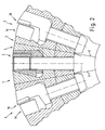
- FIG. 2 shows the arrangement of several cassettes 3 on a tool base 2 by the cassette fixing according to the invention.
- the middle cassette with the associated screw means 5 and the surrounding area of the tool base body 2 is shown in a deeper cutting plane.
- the left and right at the interfaces 17 delimiting remaining elements of the FIG. 2 are shown in a frontal view of a milling head.
- the cutting means for example in the form of PCDs, are marked with the number 18, and the chip removal areas with the numbers 19.
- the tool 1 is equipped with a variety of cassettes 3 on the circumference of the tool body 2.
- the radially inner region which is formed around the longitudinal axis of the tool, that is, the milling head, is formed materialless in the present case over a part of its axial extent, ie hollow.
- the screw means 5 can be inserted radially from inside to outside through the recesses 10 in the manner shown above.
- the left and right of the middle image area shown cassettes 3 with the associated screw 5 are arranged in slot-shaped recesses 10, wherein the slots are open to the front of the tool, so that a loosely screwed together unit of cassette parts 3A, 3B and screw 5 frontally in the milling head can be inserted and then fixed.
Landscapes
- Engineering & Computer Science (AREA)
- Mechanical Engineering (AREA)
- Milling Processes (AREA)
- Gripping On Spindles (AREA)
Claims (9)
- Outil (1) pour l'usinage par enlèvement de coupeaux de pièce à travailler, comprenant un corps de base d'outil (2), lequel tourne lors de l'usinage de la pièce, comprenant des cassettes (3), qui présentent des moyens de coupe et sont fixées à l'aide de moyens de vissage (5) sur le corps de base d'outil (2), les moyens de vissage (5) s'appuyant sur le corps de base d'outil (2) avec des moyens d'ancrage (6) présentant une surface de butée (6A), caractérisé en ce que les moyens d'ancrage (6) des moyens de vissage (5) sont disposés radialement à l'intérieur par rapport à la position de la cassette (3).
- Outil selon le préambule de la revendication 1, en particulier selon la revendication 1, caractérisé en ce que les cassettes (3) comprennent au moins deux parties, les au moins deux parties de cassette (3A, 3B) pouvant coulisser à chaque fois sur une surface de coulissement (14) l'une par rapport à l'autre, et étant fixées par les moyens de vissage (5) sur le corps de base d'outil (2) de telle sorte que, lorsque le moyen de vissage (5) est serré, une composante de force agit sur les au moins deux parties de cassette (3A, 3B) de telle sorte que des composantes de force efficaces dans le sens opposé apparaissent dans la surface de coulissement (14) sur les deux parties de cassette (3A, 3B).
- Outil selon la revendication 1 ou 2, caractérisé en ce que les moyens de vissage (5) sont disposés radialement sur le corps de base d'outil (2).
- Outil selon l'une des revendications précédentes, caractérisé en ce que les moyens d'ancrage (6) comprennent une zone (7), épaissie au niveau du sommet, des moyens de vissage (5).
- Outil selon l'une des revendications précédentes, caractérisé en ce que les moyens de vissage (5) peuvent être introduits dans le sens radial dans le corps de base d'outil (2).
- Outil selon l'une des revendications précédentes, caractérisé en ce que les moyens de vissage (5) peuvent être introduits dans le sens axial dans le corps de base d'outil (2).
- Outil selon l'une des revendications précédentes, caractérisé en ce que les moyens de vissage (5) sont accessibles par rapport à leur manipulation au moyen d'un évidement dans la cassette (3).
- Outil selon l'une des revendications précédentes 2 à 7, caractérisé en ce que sur au moins une partie de cassette (3A, 3B) est prévue une surface de butée, qui, lorsque les moyens de vissage sont dans l'état tendu, s'applique sur une paroi d'un évidement (4), formé dans le corps de base d'outil (2), pour la cassette (3) respective.
- Outil selon l'une des revendications précédentes, caractérisé en ce que la section des évidements (4) pour les cassettes (3) se rétrécit dans une direction radialement vers l'extérieur.
Applications Claiming Priority (2)
| Application Number | Priority Date | Filing Date | Title |
|---|---|---|---|
| DE202004010075U DE202004010075U1 (de) | 2003-09-18 | 2004-06-25 | Werkzeug zur spanabtragenden Bearbeitung von Werkstücken |
| PCT/DE2005/000535 WO2006000171A2 (fr) | 2004-06-25 | 2005-03-24 | Outil d'usinage de pieces par enlevement de copeaux |
Publications (2)
| Publication Number | Publication Date |
|---|---|
| EP1758703A2 EP1758703A2 (fr) | 2007-03-07 |
| EP1758703B1 true EP1758703B1 (fr) | 2013-08-21 |
Family
ID=34965129
Family Applications (1)
| Application Number | Title | Priority Date | Filing Date |
|---|---|---|---|
| EP05734878.1A Not-in-force EP1758703B1 (fr) | 2004-06-25 | 2005-03-24 | Outil d'usinage de pieces par enlevement de copeaux |
Country Status (4)
| Country | Link |
|---|---|
| US (1) | US20070104545A1 (fr) |
| EP (1) | EP1758703B1 (fr) |
| JP (1) | JP2008503361A (fr) |
| WO (1) | WO2006000171A2 (fr) |
Families Citing this family (2)
| Publication number | Priority date | Publication date | Assignee | Title |
|---|---|---|---|---|
| ATE447455T1 (de) | 2004-06-25 | 2009-11-15 | Guehring Joerg Dr | Rotor |
| US10010953B2 (en) | 2014-03-19 | 2018-07-03 | Kennametal Inc. | Wedge clamp and insert cartridge for cutting tool |
Citations (2)
| Publication number | Priority date | Publication date | Assignee | Title |
|---|---|---|---|---|
| DE19800440A1 (de) * | 1998-01-08 | 1999-07-15 | Maier Kg Andreas | Messerkopf mit ein- bis dreidimensional verstellbarem Schneideinsatz und mit formschlüssig aufgenommenem Schneideinsatz |
| US20030202848A1 (en) * | 2002-04-29 | 2003-10-30 | Gamble Kevin M. | Cutting tool |
Family Cites Families (15)
| Publication number | Priority date | Publication date | Assignee | Title |
|---|---|---|---|---|
| DE1076467B (de) * | 1954-05-06 | 1960-02-25 | Bruno Kralowetz Dipl Ing | Fraeser zum Form- oder Planfraesen |
| US2989800A (en) * | 1957-08-08 | 1961-06-27 | Comly Elwood Howard | Rotary cutters |
| DE1143082B (de) * | 1960-06-03 | 1963-01-31 | Montanwerke Walter A G | Spanneinrichtung zum Klemmen von Schneidplatten in keilfoermigen Ausschnitten des Fraesergrundkoerpers |
| DE2639890B2 (de) * | 1976-09-04 | 1981-04-23 | Heinlein, Hans, 8502 Zirndorf | Scheibenfräser |
| US4506715A (en) * | 1983-05-11 | 1985-03-26 | Blackwell George T | Adzing bit assembly |
| US4547100A (en) * | 1983-09-28 | 1985-10-15 | The Valeron Corporation | Adjustable milling cutter |
| US4797039A (en) * | 1987-09-23 | 1989-01-10 | Gte Valenite Corporation | Cutting tool bit support |
| JPH10156617A (ja) * | 1996-11-28 | 1998-06-16 | Komatsu Koki Kk | ミーリング加工用カッタ装置 |
| IL120762A (en) * | 1997-05-02 | 2001-04-30 | Iscar Ltd | Cutting tool and bearing cutting bearing for its use |
| US5975811A (en) * | 1997-07-31 | 1999-11-02 | Briese Industrial Technologies, Inc. | Cutting insert cartridge arrangement |
| IL127827A (en) * | 1998-12-29 | 2001-08-08 | Iscar Ltd | Milling a disc |
| US6739807B2 (en) * | 2001-11-26 | 2004-05-25 | Valenite Llc | Rotatable cutting tool |
| IL154472A (en) * | 2003-02-16 | 2007-10-31 | Amir Satran | Cutting tool and cartridge for it |
| US6942432B2 (en) * | 2003-03-28 | 2005-09-13 | Sandvik Intellectual Property Ab | Milling cutter and insert-carrying cartridge for use therein |
| IL159157A (en) * | 2003-12-02 | 2008-03-20 | Amir Satran | Rotary slot milling cutter and cutting insert therefor |
-
2005
- 2005-03-24 WO PCT/DE2005/000535 patent/WO2006000171A2/fr active Application Filing
- 2005-03-24 JP JP2007516952A patent/JP2008503361A/ja active Pending
- 2005-03-24 EP EP05734878.1A patent/EP1758703B1/fr not_active Not-in-force
-
2006
- 2006-12-22 US US11/644,780 patent/US20070104545A1/en not_active Abandoned
Patent Citations (2)
| Publication number | Priority date | Publication date | Assignee | Title |
|---|---|---|---|---|
| DE19800440A1 (de) * | 1998-01-08 | 1999-07-15 | Maier Kg Andreas | Messerkopf mit ein- bis dreidimensional verstellbarem Schneideinsatz und mit formschlüssig aufgenommenem Schneideinsatz |
| US20030202848A1 (en) * | 2002-04-29 | 2003-10-30 | Gamble Kevin M. | Cutting tool |
Also Published As
| Publication number | Publication date |
|---|---|
| US20070104545A1 (en) | 2007-05-10 |
| EP1758703A2 (fr) | 2007-03-07 |
| WO2006000171A2 (fr) | 2006-01-05 |
| WO2006000171A3 (fr) | 2006-04-13 |
| JP2008503361A (ja) | 2008-02-07 |
Similar Documents
| Publication | Publication Date | Title |
|---|---|---|
| EP1996358B1 (fr) | Outil de forage et tête d'outil pour outil de forage | |
| EP0282090B1 (fr) | Fraise à plaquettes | |
| DE60132455T2 (de) | Drehendes werkzeug mit einem ersetzbaren schneideinsatz an einem ende | |
| EP1885517B1 (fr) | Porte-outil a reglage precis | |
| EP0325212B1 (fr) | Tête de fraisage | |
| WO2003068439A1 (fr) | Alesoir machine | |
| EP1864741B1 (fr) | Outil pour l'usinage d'une pièce | |
| DE102017119524A1 (de) | Schnittstelle zwischen einer Spannzangenaufnahme und einem Werkzeugadapter | |
| EP2832478A1 (fr) | Système de connexion et douille intermédiaire et kit doté d'une douille intermédiaire et d'une vis d'arrêt destinée à être utilisée dans un tel système de connexion | |
| WO2011032921A1 (fr) | Outil de frottement pour l'usinage d'une pièce par enlèvement de copeaux | |
| WO2004018134A1 (fr) | Outil d'usinage par enlèvement de copeaux | |
| EP3016770B1 (fr) | Système de tête interchangeable pour l'usinage de métaux | |
| WO2004016379A1 (fr) | Outil de coupe concu pour effectuer un usinage par enlevement de copeaux | |
| EP1758703B1 (fr) | Outil d'usinage de pieces par enlevement de copeaux | |
| EP2464479B1 (fr) | Outil de fraisage, en particulier outil de fraisage à fileter | |
| EP1410864A1 (fr) | Outil ou fraise de filetage et méthode de sa fabrication | |
| EP0033086B1 (fr) | Outil de perçage avec plaquette indexable | |
| EP2114601B1 (fr) | Porte-outil | |
| DE202004010075U1 (de) | Werkzeug zur spanabtragenden Bearbeitung von Werkstücken | |
| WO2006024259A1 (fr) | Porte-outils destine a des outils de machines-outils | |
| EP4155023A1 (fr) | Logement pour un outil rotatif | |
| DE102005013616A1 (de) | Werkzeug zur spanabtragenden Bearbeitung von Werkstücken | |
| DE102008008335A1 (de) | Werkzeug zur spanenden Bearbeitung von Werkstücken | |
| DE10250018A1 (de) | Maschinenwerkzeug mit verstellbarer Schneide | |
| EP0389788A2 (fr) | Ensemble pour pratiquer des rainures à diamètre continûment variable dans la matière pleine |
Legal Events
| Date | Code | Title | Description |
|---|---|---|---|
| PUAI | Public reference made under article 153(3) epc to a published international application that has entered the european phase |
Free format text: ORIGINAL CODE: 0009012 |
|
| 17P | Request for examination filed |
Effective date: 20061028 |
|
| AK | Designated contracting states |
Kind code of ref document: A2 Designated state(s): AT BE BG CH CY CZ DE DK EE ES FI FR GB GR HU IE IS IT LI LT LU MC NL PL PT RO SE SI SK TR |
|
| 17Q | First examination report despatched |
Effective date: 20070523 |
|
| DAX | Request for extension of the european patent (deleted) | ||
| GRAP | Despatch of communication of intention to grant a patent |
Free format text: ORIGINAL CODE: EPIDOSNIGR1 |
|
| GRAS | Grant fee paid |
Free format text: ORIGINAL CODE: EPIDOSNIGR3 |
|
| GRAA | (expected) grant |
Free format text: ORIGINAL CODE: 0009210 |
|
| AK | Designated contracting states |
Kind code of ref document: B1 Designated state(s): AT BE BG CH CY CZ DE DK EE ES FI FR GB GR HU IE IS IT LI LT LU MC NL PL PT RO SE SI SK TR |
|
| REG | Reference to a national code |
Ref country code: GB Ref legal event code: FG4D Free format text: NOT ENGLISH |
|
| REG | Reference to a national code |
Ref country code: CH Ref legal event code: EP |
|
| REG | Reference to a national code |
Ref country code: AT Ref legal event code: REF Ref document number: 627763 Country of ref document: AT Kind code of ref document: T Effective date: 20130915 |
|
| REG | Reference to a national code |
Ref country code: IE Ref legal event code: FG4D Free format text: LANGUAGE OF EP DOCUMENT: GERMAN |
|
| REG | Reference to a national code |
Ref country code: DE Ref legal event code: R096 Ref document number: 502005013930 Country of ref document: DE Effective date: 20131017 |
|
| REG | Reference to a national code |
Ref country code: CH Ref legal event code: NV Representative=s name: ISLER AND PEDRAZZINI AG, CH |
|
| REG | Reference to a national code |
Ref country code: NL Ref legal event code: VDEP Effective date: 20130821 |
|
| REG | Reference to a national code |
Ref country code: LT Ref legal event code: MG4D |
|
| PG25 | Lapsed in a contracting state [announced via postgrant information from national office to epo] |
Ref country code: IS Free format text: LAPSE BECAUSE OF FAILURE TO SUBMIT A TRANSLATION OF THE DESCRIPTION OR TO PAY THE FEE WITHIN THE PRESCRIBED TIME-LIMIT Effective date: 20131221 Ref country code: PT Free format text: LAPSE BECAUSE OF FAILURE TO SUBMIT A TRANSLATION OF THE DESCRIPTION OR TO PAY THE FEE WITHIN THE PRESCRIBED TIME-LIMIT Effective date: 20131223 Ref country code: SE Free format text: LAPSE BECAUSE OF FAILURE TO SUBMIT A TRANSLATION OF THE DESCRIPTION OR TO PAY THE FEE WITHIN THE PRESCRIBED TIME-LIMIT Effective date: 20130821 Ref country code: LT Free format text: LAPSE BECAUSE OF FAILURE TO SUBMIT A TRANSLATION OF THE DESCRIPTION OR TO PAY THE FEE WITHIN THE PRESCRIBED TIME-LIMIT Effective date: 20130821 Ref country code: CY Free format text: LAPSE BECAUSE OF FAILURE TO SUBMIT A TRANSLATION OF THE DESCRIPTION OR TO PAY THE FEE WITHIN THE PRESCRIBED TIME-LIMIT Effective date: 20130717 |
|
| PG25 | Lapsed in a contracting state [announced via postgrant information from national office to epo] |
Ref country code: PL Free format text: LAPSE BECAUSE OF FAILURE TO SUBMIT A TRANSLATION OF THE DESCRIPTION OR TO PAY THE FEE WITHIN THE PRESCRIBED TIME-LIMIT Effective date: 20130821 Ref country code: FI Free format text: LAPSE BECAUSE OF FAILURE TO SUBMIT A TRANSLATION OF THE DESCRIPTION OR TO PAY THE FEE WITHIN THE PRESCRIBED TIME-LIMIT Effective date: 20130821 Ref country code: SI Free format text: LAPSE BECAUSE OF FAILURE TO SUBMIT A TRANSLATION OF THE DESCRIPTION OR TO PAY THE FEE WITHIN THE PRESCRIBED TIME-LIMIT Effective date: 20130821 Ref country code: GR Free format text: LAPSE BECAUSE OF FAILURE TO SUBMIT A TRANSLATION OF THE DESCRIPTION OR TO PAY THE FEE WITHIN THE PRESCRIBED TIME-LIMIT Effective date: 20131122 |
|
| PG25 | Lapsed in a contracting state [announced via postgrant information from national office to epo] |
Ref country code: CY Free format text: LAPSE BECAUSE OF FAILURE TO SUBMIT A TRANSLATION OF THE DESCRIPTION OR TO PAY THE FEE WITHIN THE PRESCRIBED TIME-LIMIT Effective date: 20130821 |
|
| PG25 | Lapsed in a contracting state [announced via postgrant information from national office to epo] |
Ref country code: SK Free format text: LAPSE BECAUSE OF FAILURE TO SUBMIT A TRANSLATION OF THE DESCRIPTION OR TO PAY THE FEE WITHIN THE PRESCRIBED TIME-LIMIT Effective date: 20130821 Ref country code: CZ Free format text: LAPSE BECAUSE OF FAILURE TO SUBMIT A TRANSLATION OF THE DESCRIPTION OR TO PAY THE FEE WITHIN THE PRESCRIBED TIME-LIMIT Effective date: 20130821 Ref country code: RO Free format text: LAPSE BECAUSE OF FAILURE TO SUBMIT A TRANSLATION OF THE DESCRIPTION OR TO PAY THE FEE WITHIN THE PRESCRIBED TIME-LIMIT Effective date: 20130821 Ref country code: DK Free format text: LAPSE BECAUSE OF FAILURE TO SUBMIT A TRANSLATION OF THE DESCRIPTION OR TO PAY THE FEE WITHIN THE PRESCRIBED TIME-LIMIT Effective date: 20130821 Ref country code: NL Free format text: LAPSE BECAUSE OF FAILURE TO SUBMIT A TRANSLATION OF THE DESCRIPTION OR TO PAY THE FEE WITHIN THE PRESCRIBED TIME-LIMIT Effective date: 20130821 Ref country code: EE Free format text: LAPSE BECAUSE OF FAILURE TO SUBMIT A TRANSLATION OF THE DESCRIPTION OR TO PAY THE FEE WITHIN THE PRESCRIBED TIME-LIMIT Effective date: 20130821 |
|
| PG25 | Lapsed in a contracting state [announced via postgrant information from national office to epo] |
Ref country code: ES Free format text: LAPSE BECAUSE OF FAILURE TO SUBMIT A TRANSLATION OF THE DESCRIPTION OR TO PAY THE FEE WITHIN THE PRESCRIBED TIME-LIMIT Effective date: 20130821 |
|
| PLBE | No opposition filed within time limit |
Free format text: ORIGINAL CODE: 0009261 |
|
| STAA | Information on the status of an ep patent application or granted ep patent |
Free format text: STATUS: NO OPPOSITION FILED WITHIN TIME LIMIT |
|
| 26N | No opposition filed |
Effective date: 20140522 |
|
| REG | Reference to a national code |
Ref country code: DE Ref legal event code: R097 Ref document number: 502005013930 Country of ref document: DE Effective date: 20140522 |
|
| PG25 | Lapsed in a contracting state [announced via postgrant information from national office to epo] |
Ref country code: LU Free format text: LAPSE BECAUSE OF FAILURE TO SUBMIT A TRANSLATION OF THE DESCRIPTION OR TO PAY THE FEE WITHIN THE PRESCRIBED TIME-LIMIT Effective date: 20140324 |
|
| PGFP | Annual fee paid to national office [announced via postgrant information from national office to epo] |
Ref country code: CH Payment date: 20140905 Year of fee payment: 10 |
|
| GBPC | Gb: european patent ceased through non-payment of renewal fee |
Effective date: 20140324 |
|
| REG | Reference to a national code |
Ref country code: FR Ref legal event code: ST Effective date: 20141128 |
|
| REG | Reference to a national code |
Ref country code: IE Ref legal event code: MM4A |
|
| PG25 | Lapsed in a contracting state [announced via postgrant information from national office to epo] |
Ref country code: FR Free format text: LAPSE BECAUSE OF NON-PAYMENT OF DUE FEES Effective date: 20140331 Ref country code: GB Free format text: LAPSE BECAUSE OF NON-PAYMENT OF DUE FEES Effective date: 20140324 Ref country code: IE Free format text: LAPSE BECAUSE OF NON-PAYMENT OF DUE FEES Effective date: 20140324 |
|
| PG25 | Lapsed in a contracting state [announced via postgrant information from national office to epo] |
Ref country code: IT Free format text: LAPSE BECAUSE OF NON-PAYMENT OF DUE FEES Effective date: 20140324 |
|
| REG | Reference to a national code |
Ref country code: AT Ref legal event code: MM01 Ref document number: 627763 Country of ref document: AT Kind code of ref document: T Effective date: 20140324 |
|
| PG25 | Lapsed in a contracting state [announced via postgrant information from national office to epo] |
Ref country code: AT Free format text: LAPSE BECAUSE OF NON-PAYMENT OF DUE FEES Effective date: 20140324 |
|
| REG | Reference to a national code |
Ref country code: CH Ref legal event code: PL |
|
| PG25 | Lapsed in a contracting state [announced via postgrant information from national office to epo] |
Ref country code: LI Free format text: LAPSE BECAUSE OF NON-PAYMENT OF DUE FEES Effective date: 20150331 Ref country code: CH Free format text: LAPSE BECAUSE OF NON-PAYMENT OF DUE FEES Effective date: 20150331 |
|
| PG25 | Lapsed in a contracting state [announced via postgrant information from national office to epo] |
Ref country code: MC Free format text: LAPSE BECAUSE OF FAILURE TO SUBMIT A TRANSLATION OF THE DESCRIPTION OR TO PAY THE FEE WITHIN THE PRESCRIBED TIME-LIMIT Effective date: 20130821 Ref country code: BG Free format text: LAPSE BECAUSE OF FAILURE TO SUBMIT A TRANSLATION OF THE DESCRIPTION OR TO PAY THE FEE WITHIN THE PRESCRIBED TIME-LIMIT Effective date: 20130821 |
|
| PG25 | Lapsed in a contracting state [announced via postgrant information from national office to epo] |
Ref country code: TR Free format text: LAPSE BECAUSE OF FAILURE TO SUBMIT A TRANSLATION OF THE DESCRIPTION OR TO PAY THE FEE WITHIN THE PRESCRIBED TIME-LIMIT Effective date: 20130821 Ref country code: HU Free format text: LAPSE BECAUSE OF FAILURE TO SUBMIT A TRANSLATION OF THE DESCRIPTION OR TO PAY THE FEE WITHIN THE PRESCRIBED TIME-LIMIT; INVALID AB INITIO Effective date: 20050324 Ref country code: BE Free format text: LAPSE BECAUSE OF FAILURE TO SUBMIT A TRANSLATION OF THE DESCRIPTION OR TO PAY THE FEE WITHIN THE PRESCRIBED TIME-LIMIT Effective date: 20140331 |
|
| PGFP | Annual fee paid to national office [announced via postgrant information from national office to epo] |
Ref country code: DE Payment date: 20220331 Year of fee payment: 18 |
|
| REG | Reference to a national code |
Ref country code: DE Ref legal event code: R119 Ref document number: 502005013930 Country of ref document: DE |
|
| PG25 | Lapsed in a contracting state [announced via postgrant information from national office to epo] |
Ref country code: DE Free format text: LAPSE BECAUSE OF NON-PAYMENT OF DUE FEES Effective date: 20231003 |