EP1757786A2 - Variable-throat exhaust turbocharger and method for manufacturing constituent members of variable throat mechanism - Google Patents
Variable-throat exhaust turbocharger and method for manufacturing constituent members of variable throat mechanism Download PDFInfo
- Publication number
- EP1757786A2 EP1757786A2 EP06119587A EP06119587A EP1757786A2 EP 1757786 A2 EP1757786 A2 EP 1757786A2 EP 06119587 A EP06119587 A EP 06119587A EP 06119587 A EP06119587 A EP 06119587A EP 1757786 A2 EP1757786 A2 EP 1757786A2
- Authority
- EP
- European Patent Office
- Prior art keywords
- drive ring
- nozzle
- lever plates
- connection pin
- lever
- Prior art date
- Legal status (The legal status is an assumption and is not a legal conclusion. Google has not performed a legal analysis and makes no representation as to the accuracy of the status listed.)
- Granted
Links
Images

Classifications
-
- F—MECHANICAL ENGINEERING; LIGHTING; HEATING; WEAPONS; BLASTING
- F02—COMBUSTION ENGINES; HOT-GAS OR COMBUSTION-PRODUCT ENGINE PLANTS
- F02B—INTERNAL-COMBUSTION PISTON ENGINES; COMBUSTION ENGINES IN GENERAL
- F02B37/00—Engines characterised by provision of pumps driven at least for part of the time by exhaust
- F02B37/12—Control of the pumps
- F02B37/22—Control of the pumps by varying cross-section of exhaust passages or air passages, e.g. by throttling turbine inlets or outlets or by varying effective number of guide conduits
-
- F—MECHANICAL ENGINEERING; LIGHTING; HEATING; WEAPONS; BLASTING
- F01—MACHINES OR ENGINES IN GENERAL; ENGINE PLANTS IN GENERAL; STEAM ENGINES
- F01D—NON-POSITIVE DISPLACEMENT MACHINES OR ENGINES, e.g. STEAM TURBINES
- F01D17/00—Regulating or controlling by varying flow
- F01D17/10—Final actuators
- F01D17/12—Final actuators arranged in stator parts
- F01D17/14—Final actuators arranged in stator parts varying effective cross-sectional area of nozzles or guide conduits
- F01D17/16—Final actuators arranged in stator parts varying effective cross-sectional area of nozzles or guide conduits by means of nozzle vanes
- F01D17/165—Final actuators arranged in stator parts varying effective cross-sectional area of nozzles or guide conduits by means of nozzle vanes for radial flow, i.e. the vanes turning around axes which are essentially parallel to the rotor centre line
-
- F—MECHANICAL ENGINEERING; LIGHTING; HEATING; WEAPONS; BLASTING
- F01—MACHINES OR ENGINES IN GENERAL; ENGINE PLANTS IN GENERAL; STEAM ENGINES
- F01D—NON-POSITIVE DISPLACEMENT MACHINES OR ENGINES, e.g. STEAM TURBINES
- F01D17/00—Regulating or controlling by varying flow
- F01D17/02—Arrangement of sensing elements
- F01D17/04—Arrangement of sensing elements responsive to load
-
- F—MECHANICAL ENGINEERING; LIGHTING; HEATING; WEAPONS; BLASTING
- F02—COMBUSTION ENGINES; HOT-GAS OR COMBUSTION-PRODUCT ENGINE PLANTS
- F02B—INTERNAL-COMBUSTION PISTON ENGINES; COMBUSTION ENGINES IN GENERAL
- F02B37/00—Engines characterised by provision of pumps driven at least for part of the time by exhaust
- F02B37/12—Control of the pumps
-
- F—MECHANICAL ENGINEERING; LIGHTING; HEATING; WEAPONS; BLASTING
- F05—INDEXING SCHEMES RELATING TO ENGINES OR PUMPS IN VARIOUS SUBCLASSES OF CLASSES F01-F04
- F05D—INDEXING SCHEME FOR ASPECTS RELATING TO NON-POSITIVE-DISPLACEMENT MACHINES OR ENGINES, GAS-TURBINES OR JET-PROPULSION PLANTS
- F05D2220/00—Application
- F05D2220/40—Application in turbochargers
-
- F—MECHANICAL ENGINEERING; LIGHTING; HEATING; WEAPONS; BLASTING
- F05—INDEXING SCHEMES RELATING TO ENGINES OR PUMPS IN VARIOUS SUBCLASSES OF CLASSES F01-F04
- F05D—INDEXING SCHEME FOR ASPECTS RELATING TO NON-POSITIVE-DISPLACEMENT MACHINES OR ENGINES, GAS-TURBINES OR JET-PROPULSION PLANTS
- F05D2230/00—Manufacture
- F05D2230/20—Manufacture essentially without removing material
- F05D2230/21—Manufacture essentially without removing material by casting
- F05D2230/211—Manufacture essentially without removing material by casting by precision casting, e.g. microfusing or investment casting
-
- F—MECHANICAL ENGINEERING; LIGHTING; HEATING; WEAPONS; BLASTING
- F05—INDEXING SCHEMES RELATING TO ENGINES OR PUMPS IN VARIOUS SUBCLASSES OF CLASSES F01-F04
- F05D—INDEXING SCHEME FOR ASPECTS RELATING TO NON-POSITIVE-DISPLACEMENT MACHINES OR ENGINES, GAS-TURBINES OR JET-PROPULSION PLANTS
- F05D2230/00—Manufacture
- F05D2230/30—Manufacture with deposition of material
- F05D2230/31—Layer deposition
- F05D2230/313—Layer deposition by physical vapour deposition
-
- F—MECHANICAL ENGINEERING; LIGHTING; HEATING; WEAPONS; BLASTING
- F05—INDEXING SCHEMES RELATING TO ENGINES OR PUMPS IN VARIOUS SUBCLASSES OF CLASSES F01-F04
- F05D—INDEXING SCHEME FOR ASPECTS RELATING TO NON-POSITIVE-DISPLACEMENT MACHINES OR ENGINES, GAS-TURBINES OR JET-PROPULSION PLANTS
- F05D2230/00—Manufacture
- F05D2230/30—Manufacture with deposition of material
- F05D2230/31—Layer deposition
- F05D2230/314—Layer deposition by chemical vapour deposition
-
- F—MECHANICAL ENGINEERING; LIGHTING; HEATING; WEAPONS; BLASTING
- F05—INDEXING SCHEMES RELATING TO ENGINES OR PUMPS IN VARIOUS SUBCLASSES OF CLASSES F01-F04
- F05D—INDEXING SCHEME FOR ASPECTS RELATING TO NON-POSITIVE-DISPLACEMENT MACHINES OR ENGINES, GAS-TURBINES OR JET-PROPULSION PLANTS
- F05D2230/00—Manufacture
- F05D2230/90—Coating; Surface treatment
-
- Y—GENERAL TAGGING OF NEW TECHNOLOGICAL DEVELOPMENTS; GENERAL TAGGING OF CROSS-SECTIONAL TECHNOLOGIES SPANNING OVER SEVERAL SECTIONS OF THE IPC; TECHNICAL SUBJECTS COVERED BY FORMER USPC CROSS-REFERENCE ART COLLECTIONS [XRACs] AND DIGESTS
- Y10—TECHNICAL SUBJECTS COVERED BY FORMER USPC
- Y10T—TECHNICAL SUBJECTS COVERED BY FORMER US CLASSIFICATION
- Y10T29/00—Metal working
- Y10T29/49—Method of mechanical manufacture
- Y10T29/49316—Impeller making
- Y10T29/4932—Turbomachine making
Definitions
- the present invention is applied to exhaust turbochargers for internal combustion engines and relates to the construction of a drive ring and lever plates of a variable-throat exhaust turbocharger equipped with a variable throat mechanism for varying the blade angle of a plurality of nozzle vanes and to an assembling method of the variable throat mechanism.
- the drive ring is disposed adjacent to the nozzle mount in axial direction between the side face of the lever plate and the side face of the nozzle mount, but there is disclosed no countermeasure to prevent slipping-off of the drive ring from the nozzle mount towards the lever plate side.
- said drive ring is disposed between said lever plates and nozzle mount side by side with the lever plates and nozzle mount in axial direction thereof, and a connection pin part or parts are formed protruding from a side face of the lever plate or the drive ring and integral with the material of the lever plate or the drive ring, whereby the connection pin parts of the lever plates or pin parts of the drive ring are engaged into the grooves of the drive pins or grooves of the lever plates.
- connection pin part of each of the lever plates or parts of the drive ring can be easily formed integral with each of the lever plates or drive ring by extrusion consisting of one stage of processing or by precision casting while attaining high durability of the contact surfaces of the connection pin parts and grooves by increasing the hardness of the contact surfaces to suppress abrasion of the contact surfaces, with the result that assembling man-hours and assembling cost can be reduced and the number of parts and manufacturing cost of the parts can be reduced compared with a variable threat mechanism in which the connection pins are provided separately and fixed to the lever plates or drive ring.
- said drive ring is disposed between said lever plates and nozzle mount side by side with the lever plates and nozzle mount in axial direction thereof, and rivets are fixed to the nozzle mount at its outer side face so that the outer side face of the drive ring can comes into contact with the seating faces of the rivets thereby to prevent the drive ring from moving axially.
- recesses are formed to stride across the outer side face of the drive ring and outer side face of the nozzle mount and the head of each of the rivets is received in each of the recesses.
- said drive ring is disposed between said lever plates and nozzle mount side by side with the lever plates and nozzle mount in axial direction thereof, and a plurality of partial circumferential grooves are provided at the outer side part of the nozzle mount, thereby receiving the drive ring in the partial circumferential grooves and preventing the drive ring from moving in axial direction.
- the drive ring can be positively prevented from slipping out in axial direction by such a manner that require no additional part and therefore does not result in increase in the number of parts and cost, by engaging the drive ring in the partial circumferential grooves formed at the side part of the nozzle mount, and occurrence of fail in action of the variable throat mechanism can be prevented.
- a coating layer is formed either on the surface of the connection pin part or on the surface of the groove into which the connecting part is engaged by PVD processing (physical vapor deposition processing) or by CVD(chemical vapor deposition processing).
- the wear resistance of the contact surface is increased.
- the drive ring can be positively prevented from slipping out in axial direction and occurrence of fail in action of the variable throat mechanism can be prevented, by such an extremely compact and cost saving manner as to fix a plurality of rivets to a side face of the nozzle mount, or by such a manner that requires no additional part and therefore does not result in increase in the number of parts and cost by engaging the drive ring into the partial circumferential grooves formed at a side part of the nozzle mount.
- the turbine shaft connecting the turbine rotor 34 to the compressor 35 is supported rotatably by the bearing housing 36 by means of two bearings 37, 37.
- Reference numeral 8 is an exhaust gas outlet, 40 is an axis of rotation of the exhaust turbo charger.
- Reference numeral 41 is an actuator
- 33 is an actuator rod
- 39 is a drive mechanism connecting the actuator rod 33 to a driving ring 3
- the drive mechanism converts reciprocating movement of the actuator rod into rotational movement of the drive ring.
- Reference numeral 100 is a variable throat mechanism for varying the blade angle of the nozzle vanes 2.
- variable-throat exhaust turbocharger equipped with the variable throat mechanism constructed as shown in FIG.5
- exhaust gas from an internal combustion engine(not shown in the drawing) enters the scroll 38 to flow along the volute of the scroll 38.
- the exhaust gas flows through passages between the nozzle vanes 2 into the turbine rotor 34 from the outer periphery thereof to flow radially inwardly exerting expansion work on the turbine rotor 34 to be exhausted in axial direction through the exhaust gas outlet 8 to the outside.
- Control of the variable-throat turbocharger is carried out by the actuator 41 which acts to change the blade angle of the nozzle vanes 2 to an angle position so that the exhaust gas flows through the passage between the nozzle vanes 2 at a desired flow rate, said blade angle being determined by a blade angle control means not shown in the drawing.
- Reciprocal displacement of the actuator rod 33 is converted to rotational displacement of the drive ring by the medium of the drive mechanism 39.
- Reference numeral 3 is a drive ring formed into an annular shape and supported rotatably by a nozzle mount 5. Grooves 3y are provided at the peripheral part of the drive ring 3 at equal spacing, each of connecting pin parts 10 explained later is engaged with each of the grooves. Reference numeral 3z is a driving groove with which a link of the drive mechanism 39 is engaged.
- Each of the lever plates 1 has a connecting pin part 10 formed on its face at the circumferentially outward side, and the nozzle shaft 2a of the nozzle vane 2 is fixed to the lever plate 1 at the inward side thereof.
- the lever plate 1 is disposed in the axially outer side(exhaust gas outlet side 8 in FIG.5), and the drive ring 3 is disposed between a side face of the lever plate 1 and a side face of the nozzle mount 5 side by side with the lever plates 1 and nozzle mount 5 in axial direction thereof.
- the connecting pin part 10 is formed by extrusion, in which a spot on a flat face of the lever plate 1 is pressed by a pressing machine to form a depressed portion 10a thereon to obtain a cylindrical projecting part on the other side flat face thereof, thus the connecting pin part 10 is formed in one piece with parent material, i.e. the lever plate 1.
- FIG.2A is a front view of the second embodiment of the variable throat mechanism of the present invention viewed from the lever plate side
- FIG.2B is a sectional view along line A-A in FIG.2A.
- the connecting pin parts 10(11) can be easily formed integral with the parent material by using as material of the lever plate 1 or the drive ring 3 steel material tough but relatively soft and easy to process by extrusion and applying extrusion forming to either the lever plate 1 or drive ring 3, or by precision casting.
- connection pin parts 10(11) or the grooves, into which the connection pin parts 10(11) are to be engaged with surface hardening including diffusion coating, their contact surfaces are increased in hardness and the occurrence of adhesion between the surfaces of the grooves and the connecting pin parts is prevented, with the result that abrasion of the contact surface of the connecting pin parts 10 (or 11) and grooves 3y (or 1b) can be reduced.
- connection pin parts 10 or parts 11 can be easily formed integral with each of the lever plates 1 or drive ring 3 by extrusion consisting of one stage of processing or by precision casting while attaining high durability of the contact surface by increasing the hardness of the contact surfaces of connection parts 10(or 11) and grooves 3y(or 1b) to suppress wear of the contact surfaces, with the result that assembling man-hours and assembling cost can be reduced and the number of parts and manufacturing cost of the parts can be reduced compared with a variable threat mechanism in which the connection pins are provided separately and fixed to the lever plates or drive ring.
- FIG.3A is a front view of the third embodiment of the variable throat mechanism of the present invention viewed from the lever plate side
- FIG.3B is a sectional view along line A-A in FIG.3A
- FIG.3C is a sectional view as along line C-C in FIG.3A of a modification of the third embodiment.
- a section along line A-A in FIG.3A of the third embodiment is the same as that shown in FIG.1B and FIG.2B.
- a drive ring 3 is disposed between the side face of the lever plate 1 and the a side face of a nozzle mount 5 side by side with the lever plates 1 and nozzle mount 5 in axial direction thereof as is in the case of the first and second embodiment, and a plurality of rivets 12 are fixed to the nozzle mount 5 at its outer side face so that the outer side face 3a of the drive ring 3 can come into contact with the seating faces of the rivets 12 thereby to prevent the drive ring from slipping out towards the lever plate side.
- recesses 13 are formed to stride across the outer side face 3c of the drive ring 3 and outer side face 5c of the nozzle mount 5, and the head of each of the rivets is received in each of the recesses thereby to evade the heads of the rivets from protruding than the outer side face of the lever plate 1.
- slipping out of the drive ring 3 in axial direction can be positively prevented by such an extremely compact, cost saving, and light-in-weight means as a plurality of rivets 12 (four rivets in the example shown in FIG.3A) fixed to a side face of the nozzle mount 5, with the result that occurrence of failed action of the nozzle throat mechanism 100 caused by slipping out of the drive ring 3 in the axial direction.
- FIG.4A is a front view of the second embodiment of the variable throat mechanism of the present invention viewed from the lever plate side
- FIG.4B is a sectional view along line D-D in FIG.4A.
- a section along line A-A in FIG.3A of the fourth embodiment is the same as that shown in FIG.1B.
- a plurality of engaging parts 14 which consists of a plurality of concave portions 14a formed on the inner periphery of the drive ring 3 and a plurality of convex portions 14b formed at the outer side face part 5z of the nozzle mount 5, the convex portions 14b forming outside walls of the partial circumferential grooves 15 and the bottoms of the partial circumferential grooves 15 coincide with the outer periphery of the stepped part of the nozzle mount 5.
- the drive ring 3 can be positively prevented from slipping out in axial direction by such a manner that requires no additional part and therefore does not result in increase in the number of parts and cost.
- a coating layer is formed either on the surface of the connection pin part 10 (or 11) or on the surface of the groove 3y(or 1b),(or on both the surfaces) by PVD processing(physical ion adsorption processing) or by CVD(chemical ion adsorption processing).
- the abrasive resistance of the contact surface is increased.
- a variable-throat exhaust turbocharger in which is used a means to reduce wear of the contact surfaces of the connecting pin parts which are formed integral with the lever plates or the drive ring and the grooves into which the connection pin parts are engaged, and which is provided a means to prevent slipping out of the drive ring from the nozzle mount toward the lever plate to prevent probable occurrence of fail in action of the variable nozzle mechanism caused by the slipping out of the drive ring.
Landscapes
- Engineering & Computer Science (AREA)
- Mechanical Engineering (AREA)
- General Engineering & Computer Science (AREA)
- Chemical & Material Sciences (AREA)
- Combustion & Propulsion (AREA)
- Supercharger (AREA)
- Control Of Turbines (AREA)
Abstract

Description
- The present invention is applied to exhaust turbochargers for internal combustion engines and relates to the construction of a drive ring and lever plates of a variable-throat exhaust turbocharger equipped with a variable throat mechanism for varying the blade angle of a plurality of nozzle vanes and to an assembling method of the variable throat mechanism.
- There has been proposed an art relating to the construction of a drive ring and lever plates of a variable-throat turbocharger equipped with a variable throat mechanism for varying the blade angle of a plurality of nozzle vanes in
Japanese Laid-Open Patent Application No.2002-285804 Japanese Laid-Open Patent Application No.2002-332866 - In the art disclosed in the patent literature 1, the turbocharger comprises a plurality of nozzle vanes rotatably supported by a nozzle mount fixed to a turbine casing and a variable throat mechanism which comprises an annular drive ring rotatable by means of an actuator, and lever plates, each of which lever plates has a groove at its one end side to be engaged with each of connection pins of the drive ring to be connected thereto, whereby the blade angle of the nozzle vanes is varied by rotating the drive ring to swing each of the lever plates, the blade angle being varied by the swing of the lever plates, wherein the connection pin or pins are formed either on the lever plate or on the drive ring by extrusion or by precision casting such that the connection pin or pins are formed in one piece with parent material, i.e. the lever plate or drive ring.
- In the art disclosed in the
patent literature 2, the turbocharger comprises variable blade angle nozzle vanes for adjusting the flow rate of the exhaust gas exhausted from an engine and introduced into the turbocharger to rotate the turbine rotor, a turbine frame which rotatably supports the variable blade angle nozzle vanes arranged at the peripheral part of the exhaust turbine, and a variable throat mechanism for rotating the nozzle vanes to adjust the flow rate of the exhaust gas, whereby the velocity of exhaust gas is increased by throttling the exhaust flow by the variable blade angle nozzle vanes so that high output can be obtained even at low rotation speed, and constituent members of an exhaust guide assembly of the turbocharger are surface-treated to coat the surfaces with carbide or nitride. - However, in the art of the patent literature 1, the connection pin or pins are formed either on the lever plate or on the drive ring by extrusion or by precision casting such that the connection pin or pins are formed in one piece with parent material, i.e. the lever plate or drive ring, but there is disclosed no countermeasure to deal with wear of the connection pin and groove of the link plate in which the connection pin is engaged.
- Further, in the art, the drive ring is disposed adjacent to the nozzle mount in axial direction between the side face of the lever plate and the side face of the nozzle mount, but there is disclosed no countermeasure to prevent slipping-off of the drive ring from the nozzle mount towards the lever plate side.
- In the art disclosed in the
patent literature 2 is taught surface-treating of the constituent members of the exhaust guide assembly to coat the surfaces with carbide or nitride, but concretively only the coating of the variable blade angle nozzle vanes and the turbine frame is recited, and surface treating of transmission members for transmitting rotational force to the variable blade angle nozzle vanes via movable members is not disclosed. - Further, in the art of the
patent literature 2, a ring member is provided to sandwich a rotating member between the ring member and a flange of the turbine frame and push the rotating member towards the turbine frame to prevent the rotating member from moving apart from the turbine frame. Therefore, it is necessary to provide the ring member, resulting in an increase in cost and weight, and further resulting in complication in assembling. - The present invention was made in light of the problem in prior art to improve on the art disclosed in the
patent literature 1 and 2. The object of the invention is to provide a variable-throat exhaust turbocharger in which connection pin parts which are formed integral with the lever plates or the drive ring and grooves into which the connection pin parts are engaged are treated to reduce abrasion of the contact surfaces of them, and which has a means to prevent slipping out of the drive ring from the nozzle mount toward the lever plate side to prevent probable occurrence of fail in action of the variable nozzle mechanism caused by the slipping out of the drive ring. - To attain the object, the present invention proposes a variable-throat exhaust turbocharger equipped with a variable throat mechanism comprising a plurality of nozzle vanes supported rotatably by a nozzle mount fixed to a turbine casing, an annular drive ring connected to and rotated by an actuator, and lever plates identical in number with the number of the nozzle vanes, each of the lever plates being connected at its one end to the drive ring via a connection pin and a groove into which the connection pin is engaged and at the other end connected to the nozzle vanes, whereby the lever plates are swung by rotating the drive ring and the nozzle vanes are rotated by the swing of the lever plates to vary the blade angle of the nozzle vanes, wherein a connection pin is formed integral with said lever plate by extrusion or by precision casting as a connection pin parts of the lever plate or connection pins are formed integral with said drive ring by extrusion or by precision casting as connection pin parts of the drive ring, wherein at least either the connection pin part of the lever plate/pin parts of the drive ring or grooves of the drive ring/groves of the lever plates into which the connection pin parts are engaged are treated with surface hardening including diffusion coating.
- In the invention, it is preferable concretively that said drive ring is disposed between said lever plates and nozzle mount side by side with the lever plates and nozzle mount in axial direction thereof, and a connection pin part or parts are formed protruding from a side face of the lever plate or the drive ring and integral with the material of the lever plate or the drive ring, whereby the connection pin parts of the lever plates or pin parts of the drive ring are engaged into the grooves of the drive pins or grooves of the lever plates.
- The invention proposes as a method for manufacturing a variable-throat exhaust turbocharger equipped with a variable throat mechanism constructed as mentioned above, in which a connection pin part is formed on a lever plate in one piece with the lever plate by pressing a spot on a flat face thereof to allow the pin part to be protruded from the other side flat face thereof or is formed by precision casting on a flat face of a lever plate in one piece with the lever plate, or a plurality of connection pin parts are formed on a drive ring in one piece with the drive ring by pressing a plurality of spots on a flat face thereof to allow the pin parts to be protruded from the other side flat face of the drive ring or are formed by precision casting on a flat face of a drive ring in one piece with the drive ring, then at least either the connection pin part of the lever plate/pin parts of the drive ring or grooves of the drive ring/groves of the lever plates are treated with surface hardening including diffusion coating.
- According to the invention, the connecting pin parts can be easily formed integral with the parent material, the lever plates or drive ring, by using as material of the lever plate or the drive ring steel material tough but relatively soft and easy to process by extrusion and applying extrusion forming to either the lever plates or drive ring, or by precision casting. Further, by treating at least the connection pin parts or the grooves, into which the connection pin parts are to be engaged, with surface hardening including diffusion coating, their contact surfaces are increased in hardness and abrasion of the contact surfaces is reduced.
- Thus, the connection pin part of each of the lever plates or parts of the drive ring can be easily formed integral with each of the lever plates or drive ring by extrusion consisting of one stage of processing or by precision casting while attaining high durability of the contact surfaces of the connection pin parts and grooves by increasing the hardness of the contact surfaces to suppress abrasion of the contact surfaces, with the result that assembling man-hours and assembling cost can be reduced and the number of parts and manufacturing cost of the parts can be reduced compared with a variable threat mechanism in which the connection pins are provided separately and fixed to the lever plates or drive ring.
- In the invention, it is preferable that said drive ring is disposed between said lever plates and nozzle mount side by side with the lever plates and nozzle mount in axial direction thereof, and rivets are fixed to the nozzle mount at its outer side face so that the outer side face of the drive ring can comes into contact with the seating faces of the rivets thereby to prevent the drive ring from moving axially.
- Further, it is preferable that recesses are formed to stride across the outer side face of the drive ring and outer side face of the nozzle mount and the head of each of the rivets is received in each of the recesses.
- According to the invention like this, slipping out of the drive ring in axial direction can be positively prevented by such an extremely compact, cost saving, and light-in-weight means as to fix a plurality of rivets to the side face of the nozzle mount, with the result that occurrence of failed action of the nozzle throat mechanism caused by slipping out of the drive ring in axial direction can be prevented.
- It is preferable that said drive ring is disposed between said lever plates and nozzle mount side by side with the lever plates and nozzle mount in axial direction thereof, and a plurality of partial circumferential grooves are provided at the outer side part of the nozzle mount, thereby receiving the drive ring in the partial circumferential grooves and preventing the drive ring from moving in axial direction.
- It is also preferable that a plurality of engaging portions are provided, the engaging portions being composed of convex portions and concave portions provided either to the drive ring or nozzle mount respectively, so that the drive ring can be fitted to the nozzle mount by matching the convex portions and concave portions and shifting axially the drive ring relative to the nozzle mount, whereby the drive ring is allowed to be engaged into said partial circumferential grooves by shifting the drive ring in rotation direction after the drive ring is fitted to the nozzle mount.
- A method of manufacturing a variable-throat exhaust turbocharger equipped with a variable throat mechanism constructed as mentioned above is characterized in that; a drive ring is disposed between said lever plates and nozzle mount, the nozzle mount being provided with a plurality of partial circumferential grooves at the outer side part thereof, side by side with the lever plates and nozzle mount in axial direction thereof, and a plurality of engaging portions are provided, the engaging portions being composed of convex portions and concave portions provided either to the drive ring or nozzle mount respectively, so that the drive ring can be fitted to the nozzle mount by matching the convex portions and concave portions and shifting axially the drive ring relative to the nozzle mount, whereby the drive ring is allowed to be engaged into said partial circumferential grooves by shifting the drive ring in rotation direction by a certain angle after the drive ring is fitted to the nozzle mount thereby to prevent slipping out axially of the drive ring, and said lever plates are attached to said drive ring and connected with nozzle shafts of the nozzle vanes, the nozzle shafts penetrating the nozzle mount, with the nozzle mount sandwiched with the lever plates and nozzle vanes.
- According to the invention, the drive ring can be positively prevented from slipping out in axial direction by such a manner that require no additional part and therefore does not result in increase in the number of parts and cost, by engaging the drive ring in the partial circumferential grooves formed at the side part of the nozzle mount, and occurrence of fail in action of the variable throat mechanism can be prevented.
- Further, it is preferable that a coating layer is formed either on the surface of the connection pin part or on the surface of the groove into which the connecting part is engaged by PVD processing (physical vapor deposition processing) or by CVD(chemical vapor deposition processing).
- According to the invention like this, by forming a hard coating layer on the contact surface of the connection pin part and the groove into which the connection pin part is engaged by PVD or CVD processing, the wear resistance of the contact surface is increased.
- According to the present invention, hardness of the contact surface of the connection pin part and the groove into which the connection pin part is engaged can be increased by treating the contact surface with surface hardening including diffusion coating. Therefore, each of the connection pin parts can be easily formed integral with each of the lever plates or drive ring by extrusion consisting of one stage of processing or by precision casting while attaining high durability of the contact surface by increasing the hardness of said contact surface to suppress abrasion of the contact surface, with the result that assembling man-hours and assembling cost can be reduced and the number of parts and manufacturing cost of parts can be reduced compared with a variable threat mechanism in which the connection pins are provided separately and fixed to the lever plates or drive ring.
- As to surface hardening, in the case of steel-to-steel contact, the contact surface tends to be seriously worn by the occurrence of adhesion (adhesive wear), but when the surface of a member of contacting members is treated with surface hardening, the surface is hardened by the generation of ceramics or intermetallic compounds on the surface and adhesive wear is alleviated. As surface coarsening caused by sliding contact is prevented by surface hardening, occurrence of scratch on the surface can be lessened and occurrence of abrasive wear can be alleviated even when the surface of the other member of contacting members is not treated with surface hardening.
- Therefore, reduction of wear of the contact surface can be expected by treating only the surface of a member of contacting members with surface hardening.
- Further, according to the invention, the drive ring can be positively prevented from slipping out in axial direction and occurrence of fail in action of the variable throat mechanism can be prevented, by such an extremely compact and cost saving manner as to fix a plurality of rivets to a side face of the nozzle mount, or by such a manner that requires no additional part and therefore does not result in increase in the number of parts and cost by engaging the drive ring into the partial circumferential grooves formed at a side part of the nozzle mount.
-
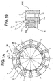
- FIG.1A is a front view of the first embodiment of the variable throat mechanism of the present invention viewed from the lever plate side, and FIG. 1B is a sectional view along line A-A in FIG. 1A.
- FIG.2A is a front view of the second embodiment of the variable throat mechanism of the present invention viewed from the lever plate side, and FIG.2B is a sectional view along line A-A in FIG.2A.
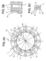
- FIG.3A is a front view of the third embodiment of the variable throat mechanism of the present invention viewed from the lever plate side, FIG. 3B is a sectional view along line A-A in FIG.2A, and FIG.3C is a sectional view as along line C-C in FIG.3A of a modification of the third embodiment.
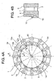
- FIG.4A is a front view of the second embodiment of the variable throat mechanism of the present invention viewed from the lever plate side, and FIG.4B is a sectional view along line D-D in FIG.4A.
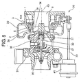
- FIG.5 is a longitudinal sectional view of the variable-throat turbocharger equipped with the variable throat mechanism according to the present invention.
- A preferred embodiment of the present invention will now be detailed with reference to the accompanying drawings. It is intended, however, that unless particularly specified, dimensions, materials, relative positions and so forth of the constituent parts in the embodiments shall be interpreted as illustrative only not as limitative of the scope of the present invention.
- FIG.5 is a longitudinal sectional view of the variable-throat turbocharger equipped with the variable throat mechanism according to the present invention.
- Referring to FIG.5,
reference numeral 30 is a turbine casing, 38 is a scroll formed vorticosely in the peripheral part of theturbine casing 30.Reference numeral 34 is a turbine rotor of radial flow type, 35 is a compressor, 32 is a turbine shaft connecting theturbine rotor 34 to thecompressor - The turbine shaft connecting the
turbine rotor 34 to thecompressor 35 is supported rotatably by the bearinghousing 36 by means of twobearings -
Reference numeral 2 is a nozzle vane, a plurality of the nozzle vanes are arranged at equal spacing in the inward side periphery of thescroll 38, and anozzle shaft 2a formed at a side face of the nozzle vane is supported rotatably by anozzle mount 2 fixed to theturbine casing 30. -
Reference numeral 41 is an actuator, 33 is an actuator rod, and 39 is a drive mechanism connecting theactuator rod 33 to adriving ring 3, the drive mechanism converts reciprocating movement of the actuator rod into rotational movement of the drive ring. -
Reference numeral 100 is a variable throat mechanism for varying the blade angle of thenozzle vanes 2. - In the operation of the variable-throat exhaust turbocharger equipped with the variable throat mechanism constructed as shown in FIG.5, exhaust gas from an internal combustion engine(not shown in the drawing) enters the
scroll 38 to flow along the volute of thescroll 38. The exhaust gas flows through passages between the nozzle vanes 2 into theturbine rotor 34 from the outer periphery thereof to flow radially inwardly exerting expansion work on theturbine rotor 34 to be exhausted in axial direction through the exhaust gas outlet 8 to the outside. - Control of the variable-throat turbocharger is carried out by the
actuator 41 which acts to change the blade angle of thenozzle vanes 2 to an angle position so that the exhaust gas flows through the passage between thenozzle vanes 2 at a desired flow rate, said blade angle being determined by a blade angle control means not shown in the drawing. Reciprocal displacement of theactuator rod 33 is converted to rotational displacement of the drive ring by the medium of thedrive mechanism 39. - By the rotation of the drive ring is swung each of lever plates 1 around the center axis of each of the
nozzle shafts 2a via each of connecting pin parts 10 (or 11) to rotate each of thenozzle shafts 2a. The nozzle vanes are rotated by the rotation of thenozzle shafts 2a to change the blade angle to said desired angle position. - The present invention relates to an improvement of the
variable throat mechanism 100 for controlling the flow rate of exhaust gas flowing through the variable-throat turbine like this. - FIG.1A is a front view of the first embodiment of the variable throat mechanism of the present invention viewed from the leverplate side, and FIG. 1B is a sectional view along line A-A in FIG. 1A.
-
Reference numeral 100 is a variable nozzle mechanism for varying the blade angle of thenozzle vanes 2 and constructed as follows. -
Reference numeral 3 is a drive ring formed into an annular shape and supported rotatably by anozzle mount 5. Grooves 3y are provided at the peripheral part of thedrive ring 3 at equal spacing, each of connectingpin parts 10 explained later is engaged with each of the grooves.Reference numeral 3z is a driving groove with which a link of thedrive mechanism 39 is engaged. - Reference numeral 1 indicates lever plates disposed on the peripheral part of the
drive ring 3 corresponding to the grooves 3y in number. - Each of the lever plates 1 has a connecting
pin part 10 formed on its face at the circumferentially outward side, and thenozzle shaft 2a of thenozzle vane 2 is fixed to the lever plate 1 at the inward side thereof. - Reference numeral 6 is a support plate formed into an annular shape, 7 indicates nozzle supports for connecting the support plate 6 to the
nozzle mount 5. - In the variable
nozzle throat mechanism 100, as shown in FIG.1B, the lever plate 1 is disposed in the axially outer side(exhaust gas outlet side 8 in FIG.5), and thedrive ring 3 is disposed between a side face of the lever plate 1 and a side face of thenozzle mount 5 side by side with the lever plates 1 andnozzle mount 5 in axial direction thereof. - The connecting
pin part 10 is formed by extrusion, in which a spot on a flat face of the lever plate 1 is pressed by a pressing machine to form adepressed portion 10a thereon to obtain a cylindrical projecting part on the other side flat face thereof, thus the connectingpin part 10 is formed in one piece with parent material, i.e. the lever plate 1. - The lever plate can be also made by precision casting to have the connecting
pin part 10 integral with the lever plate. - At least one of the periphery of the
connection pin part 10 and the surface of the groove 3y, into which is to be engaged the connectingpin part 10, of thedrive ring 3, is treated by surface hardening such as chrome diffusion coating, aluminum diffusion coating, vanadium diffusion coating, niobium diffusion coating, boron diffusion coating, nitriding, or combined treating of said diffusion coating and carburizing. - To manufacture the
variable throat mechanism 100 constructed as mentioned above, aconnection pin part 10 is formed to protrude from the lever plate 1 in one piece therewith by pressing by a pressing machine a spot on a flat face of the lever plate 1 so that a cylindricallydepressed portion 10a is formed on the other side flat face of the lever plate. On thedrive ring 3 are formed the grooves 3y by machining, or the grooves 3y are formed by precision casting when the drive ring is made by precision casting. - Then, at least one of the periphery of the
connection pin part 10 and the surface of the groove 3y, into which the connectingpin part 10 is to be engaged, of thedrive ring 3, is treated for surface hardening as mentioned above. - FIG.2A is a front view of the second embodiment of the variable throat mechanism of the present invention viewed from the lever plate side, and FIG.2B is a sectional view along line A-A in FIG.2A.
- In the second embodiment, a plurality of spots lining up circumferentially at equal spacing on a flat face of a
drive ring 3 are pressed by a pressing machine to form cylindricaldepressed portions 3a each of which is similar to that of the first embodiment to obtain cylindrical projecting parts on the other side flat face thereof, thus connectingpin parts 11 are formed in one piece with parent material, i.e. thedrive ring 3. Each of lever plates 1 is formed to have two-forked part at the outward side thereof to form agroove 1b to be engaged with one of the connectingpin parts 11 of thedrive ring 3. - Otherwise is identical in construction to the first embodiment, and constituent parts similar to those of the first embodiment are denoted by the same reference numerals respectively.
- According to the first and second embodiment, the connecting pin parts 10(11) can be easily formed integral with the parent material by using as material of the lever plate 1 or the
drive ring 3 steel material tough but relatively soft and easy to process by extrusion and applying extrusion forming to either the lever plate 1 or drivering 3, or by precision casting. - Further, by treating at least the connection pin parts 10(11) or the grooves, into which the connection pin parts 10(11) are to be engaged, with surface hardening including diffusion coating, their contact surfaces are increased in hardness and the occurrence of adhesion between the surfaces of the grooves and the connecting pin parts is prevented, with the result that abrasion of the contact surface of the connecting pin parts 10 (or 11) and grooves 3y (or 1b) can be reduced.
- Thus, each of the
connection pin parts 10 orparts 11 can be easily formed integral with each of the lever plates 1 or drivering 3 by extrusion consisting of one stage of processing or by precision casting while attaining high durability of the contact surface by increasing the hardness of the contact surfaces of connection parts 10(or 11) and grooves 3y(or 1b) to suppress wear of the contact surfaces, with the result that assembling man-hours and assembling cost can be reduced and the number of parts and manufacturing cost of the parts can be reduced compared with a variable threat mechanism in which the connection pins are provided separately and fixed to the lever plates or drive ring. - FIG.3A is a front view of the third embodiment of the variable throat mechanism of the present invention viewed from the lever plate side, FIG.3B is a sectional view along line A-A in FIG.3A. FIG.3C is a sectional view as along line C-C in FIG.3A of a modification of the third embodiment. A section along line A-A in FIG.3A of the third embodiment is the same as that shown in FIG.1B and FIG.2B.
- In the third embodiment, a
drive ring 3 is disposed between the side face of the lever plate 1 and the a side face of anozzle mount 5 side by side with the lever plates 1 andnozzle mount 5 in axial direction thereof as is in the case of the first and second embodiment, and a plurality ofrivets 12 are fixed to thenozzle mount 5 at its outer side face so that theouter side face 3a of thedrive ring 3 can come into contact with the seating faces of therivets 12 thereby to prevent the drive ring from slipping out towards the lever plate side. - In the third embodiment, it is also possible that recesses 13 are formed to stride across the outer side face 3c of the
drive ring 3 and outer side face 5c of thenozzle mount 5, and the head of each of the rivets is received in each of the recesses thereby to evade the heads of the rivets from protruding than the outer side face of the lever plate 1. - According to the third embodiment, slipping out of the
drive ring 3 in axial direction can be positively prevented by such an extremely compact, cost saving, and light-in-weight means as a plurality of rivets 12 (four rivets in the example shown in FIG.3A) fixed to a side face of thenozzle mount 5, with the result that occurrence of failed action of thenozzle throat mechanism 100 caused by slipping out of thedrive ring 3 in the axial direction. - Otherwise is identical in construction to those of the first embodiment, and constituent parts similar to those of the first embodiment are denoted by the same reference numerals respectively.
- FIG.4A is a front view of the second embodiment of the variable throat mechanism of the present invention viewed from the lever plate side, and FIG.4B is a sectional view along line D-D in FIG.4A. A section along line A-A in FIG.3A of the fourth embodiment is the same as that shown in FIG.1B.
- In the fourth embodiment, a
drive ring 3 is disposed between the side face of the lever plate 1 and the a side face of anozzle mount 5 side by side with the lever plates 1 andnozzle mount 5 in axial direction thereof as is in the case of the first and second embodiment, and a plurality of partialcircumferential grooves 15 are provided at the outer side part of thenozzle mount 5. Thedrive ring 3 is received in the partialcircumferential grooves 15 and prevented by the side face of thegroove 15 from slipping out towards the lever plate 1. - More specifically, as shown in FIG.4A, a plurality of engaging
parts 14 are provided which consists of a plurality ofconcave portions 14a formed on the inner periphery of thedrive ring 3 and a plurality ofconvex portions 14b formed at the outer side face part 5z of thenozzle mount 5, theconvex portions 14b forming outside walls of the partialcircumferential grooves 15 and the bottoms of the partialcircumferential grooves 15 coincide with the outer periphery of the stepped part of thenozzle mount 5. - When assembling the
variable throat mechanism 100 of the fourth embodiment, thedrive ring 3 is pushed towards the nozzle mount with theconcave portions 14a of thedrive ring 3 matched with theconvex portions 14b of thenozzle mount 5 to fit thedrive ring 3 on the inner periphery of the stepped part of thenozzle mount 5. Then thedrive ring 3 is rotated by a certain rotation angle relative to thenozzle mount 5 so that the inner peripheral part of the drive ring is engaged with the partialcircumferential grooves 15 to prevent thedrive ring 3 from slipping in axial direction. Then the lever plates 1 are attached to thedrive ring 3 and connected with thenozzle shafts 2a penetrating thenozzle mount 5, sandwiching thenozzle mount 2. - Otherwise is identical in construction to those of the first embodiment, and constituent parts similar to those of the first embodiment are denoted by the same reference numerals respectively.
- According to the fourth embodiment, the
drive ring 3 can be positively prevented from slipping out in axial direction by such a manner that requires no additional part and therefore does not result in increase in the number of parts and cost. By engaging thedrive ring 3 into the partialcircumferential grooves 15 formed at the side part 5z of thenozzle mount 5, and occurrence of fail in action of the variable throat mechanism can be prevented. - In the fifth embodiment of the invention, in the variable exhaust turbocharger equipped with the variable
nozzle throat mechanism 100 as shown in FIG.1 to FIG.4, a coating layer is formed either on the surface of the connection pin part 10 (or 11) or on the surface of the groove 3y(or 1b),(or on both the surfaces) by PVD processing(physical ion adsorption processing) or by CVD(chemical ion adsorption processing). - According to the fifth embodiment, by forming a hard coating layer on the contact surface of the connection pin part 10 (or 11) with the groove 3y (or 1b) into which the
connection pin part 10 is engaged by PVD or CVD processing, the abrasive resistance of the contact surface is increased. - According to the present invention, a variable-throat exhaust turbocharger can be provided, in which is used a means to reduce wear of the contact surfaces of the connecting pin parts which are formed integral with the lever plates or the drive ring and the grooves into which the connection pin parts are engaged, and which is provided a means to prevent slipping out of the drive ring from the nozzle mount toward the lever plate to prevent probable occurrence of fail in action of the variable nozzle mechanism caused by the slipping out of the drive ring.
Claims (9)
- A variable-throat exhaust turbocharger equipped with a variable throat mechanism comprising a plurality of nozzle vanes supported rotatably by a nozzle mount fixed to a turbine casing, an annular drive ring connected to and rotated by an actuator, and lever plates identical in number with the number of the nozzle vanes, each of the lever plates being connected at its one end to the drive ring via a connection pin and a groove into which the connection pin is engaged and at the other end connected to the nozzle vanes, whereby the lever plates are swung by rotating the drive ring and the nozzle vanes are rotated by the swing of the lever plates to vary the blade angle of the nozzle vanes,
wherein a connecting pin is formed integral with said lever plate by extrusion or by precision casting as a connection pin parts of the lever plate or connecting pins are formed integral with said drive ring by extrusion or by precision casting as connection pin parts of the drive ring, wherein at least either the connection pin part of the lever plate/pin parts of the drive ring or grooves of the drive ring/groves of the lever plates into which the connection pin parts are engaged are treated with surface hardening including diffusion coating. - A variable-throat exhaust turbocharger equipped with a variable throat mechanism according to claim 1,
wherein said drive ring is disposed between said lever plates and nozzle mount side by side with the lever plates and nozzle mount in axial direction thereof, and a connection pin part or parts are formed protruding from a side face of the lever plate or the drive ring and integral with the material of the lever plate or the drive ring, whereby the connection pin parts of the lever plates or pin parts of the drive ring are engaged into the grooves of the drive pins or grooves of the lever plates. - A method for manufacturing a variable-throat exhaust turbocharger equipped with a variable throat mechanism comprising a plurality of nozzle vanes supported rotatably by a nozzle mount fixed to a turbine casing, an annular drive ring connected to and rotated by an actuator, and lever plates identical in number with the number of the nozzle vanes, each of the lever plates being connected at its one end connected to the drive ring via a connection pin and a groove into which the connection pin is engaged and at the other end to the nozzle vanes, whereby the lever plates are swung by rotating the drive ring and the nozzle vanes are rotated by the swing of the lever plates to vary the blade angle of the nozzle vanes,
wherein a connection pin part is formed on a lever plate in one piece with the lever plate by pressing a spot on a flat face thereof to allow the pin part to be protruded from the other side flat face thereof or is formed by precision casting on a flat face of a lever plate in one piece with the lever plate, or a plurality of connection pin parts are formed on a drive ring in one piece with the drive ring by pressing a plurality of spots on a flat face thereof to allow the pin parts to be protruded from the other side flat face of the drive ring or are formed by precision casting on a flat face of a drive ring in one piece with the drive ring, then at least either the connection pin part of the lever plate/pin parts of the drive ring or grooves of the drive ring/groves of the lever plates are treated with surface hardening including diffusion coating. - A variable-throat exhaust turbocharger equipped with a variable throat mechanism comprising a plurality of nozzle vanes supported rotatably by a nozzle mount fixed to a turbine casing, an annular drive ring connected to and rotated by an actuator, and lever plates identical in number with the number of the nozzle vanes, each of the lever plates being connected at its one end to the drive ring via a connection pin and a groove into which the connection pin is engaged and at the other end connected to the nozzle vanes, whereby the lever plates are swung by rotating the drive ring and the nozzle vanes are rotated by the swing of the lever plates to vary the blade angle of the nozzle vanes,
wherein said drive ring is disposed between said lever plates and nozzle mount side by side with the lever plates and nozzle mount in axial direction thereof, and rivets are fixed to the nozzle mount at its outside face so that the outer side face of the drive ring 3 can comes into contact with the seating faces of the rivets thereby to prevented the drive ring from moving axially. - A variable-throat exhaust turbocharger equipped with a variable throat mechanism according to claim 4,
wherein recesses are formed to stride across the outer side face of the drive ring and outer side face of the nozzle mount and the head of each of the rivets is received in each of the recesses. - A variable-throat exhaust turbocharger equipped with a variable throat mechanism comprising a plurality of nozzle vanes supported rotatably by a nozzle mount fixed to a turbine casing, an annular drive ring connected to and rotated by an actuator, and lever plates identical in number with the number of the nozzle vanes, each of the lever plates being connected at its one end to the drive ring via a connection pin and a groove into which the connection pin is engaged and at the other end connected to the nozzle vanes, whereby the lever plates are swung by rotating the drive ring and the nozzle vanes are rotated by the swing of the lever plates to vary the blade angle of the nozzle vanes,
wherein said drive ring is disposed between said lever plates and nozzle mount side by side with the lever plates and nozzle mount in axial direction thereof, and a plurality of partial circumferential grooves are provided at the outer side part of the nozzle mount, thereby receiving the drive ring in the partial circumferential grooves and preventing the drive ring from moving in axial direction. - A variable-throat exhaust turbocharger equipped with a variable throat mechanism according to claim 6,
wherein a plurality of engaging portions are provided, the engaging portions being composed of convex portions and concave portions provided either to the drive ring or nozzle mount respectively, so that the drive ring can be fitted to the nozzle mount by matching the convex portions and concave portions and shifting axially the drive ring relative to the nozzle mount, whereby the drive ring is allowed to be engaged into said partial circumferential grooves by shifting the drive ring in rotation direction after the drive ring is fitted to the nozzle mount. - A method for manufacturing a variable-throat exhaust turbocharger equipped with a variable throat mechanism comprising a plurality of nozzle vanes supported rotatably by a nozzle mount fixed to a turbine casing, an annular drive ring connected to and rotated by an actuator, and lever plates identical in number with the number of the nozzle vanes, each of the lever plates being connected at its one end to the drive ring via a connection pin and a groove into which the connection pin is engaged and at the other end connected to the nozzle vanes, whereby the lever plates are swung by rotating the drive ring and the nozzle vanes are rotated by the swing of the lever plates to vary the blade angle of the nozzle vanes,
wherein said drive ring is disposed between said lever plates and nozzle mount, the nozzle mount being provided with a plurality of partial circumferential grooves at the outer side part thereof, side by side with the lever plates and nozzle mount in axial direction thereof, and a plurality of engaging portions are provided, the engaging portions being composed of convex portions and concave portions provided either to the drive ring or nozzle mount respectively, so that the drive ring can be fitted to the nozzle mount by matching the convex portions and concave portions and shifting axially the drive ring relative to the nozzle mount, whereby the drive ring is allowed to be engaged into said partial circumferential grooves by shifting the drive ring in rotation direction by a certain angle after the drive ring is fitted to the nozzle mount thereby to prevent slipping out axially of the drive ring, and wherein said lever plates are attached to said drive ring and connected with nozzle shafts of the nozzle vanes, the nozzle shafts penetrating the nozzle mount, with the nozzle mount sandwiched with the lever plates and nozzle vanes. - A variable-throat exhaust turbocharger equipped with a variable throat mechanism comprising a plurality of nozzle vanes supported rotatably by a nozzle mount fixed to a turbine casing, an annular drive ring connected to and rotated by an actuator, and lever plates identical in number with the number of the nozzle vanes, each of the lever plates being connected at its one end to the drive ring via a connection pin and a groove into which the connection pin is engaged and at the other end connected to the nozzle vanes, whereby the lever plates are swung by rotating the drive ring and the nozzle vanes are rotated by the swing of the lever plates to vary the blade angle of the nozzle vanes,
wherein a coating layer is formed either on the surface of the connection pin part or on the surface of the groove into which the connection pin part is engaged by PVD processing (physical vapor deposition processing) or by CVD(chemical vapor deposition processing).
Applications Claiming Priority (1)
| Application Number | Priority Date | Filing Date | Title |
|---|---|---|---|
| JP2005243829A JP4545068B2 (en) | 2005-08-25 | 2005-08-25 | Variable displacement exhaust turbocharger and variable nozzle mechanism component manufacturing method |
Publications (3)
| Publication Number | Publication Date |
|---|---|
| EP1757786A2 true EP1757786A2 (en) | 2007-02-28 |
| EP1757786A3 EP1757786A3 (en) | 2014-08-13 |
| EP1757786B1 EP1757786B1 (en) | 2018-05-02 |
Family
ID=37462254
Family Applications (1)
| Application Number | Title | Priority Date | Filing Date |
|---|---|---|---|
| EP06119587.1A Not-in-force EP1757786B1 (en) | 2005-08-25 | 2006-08-25 | Variable-throat exhaust turbocharger and method for manufacturing constituent members of variable throat mechanism |
Country Status (6)
| Country | Link |
|---|---|
| US (1) | US7406826B2 (en) |
| EP (1) | EP1757786B1 (en) |
| JP (1) | JP4545068B2 (en) |
| KR (1) | KR101330400B1 (en) |
| CN (3) | CN101344017A (en) |
| BR (1) | BRPI0605188B1 (en) |
Cited By (6)
| Publication number | Priority date | Publication date | Assignee | Title |
|---|---|---|---|---|
| DE102008058509A1 (en) * | 2008-11-21 | 2010-05-27 | Bosch Mahle Turbo Systems Gmbh & Co. Kg | Exhaust gas turbo loader for motor vehicles, comprises a variable turbine-/compressor geometry that has guide vanes rotatably arranged in annular guide conduit over a front bearing pin, and an adjustable ring for adjusting the guide vanes |
| DE102009014917A1 (en) * | 2009-03-25 | 2010-09-30 | Bosch Mahle Turbo Systems Gmbh & Co. Kg | Charging unit, particularly exhaust turbo charger for motor vehicle, has variable turbine- or compressor geometry with vane mounting ring, multiple guide vanes and adjustment ring for adjusting guide vanes |
| EP2067959A4 (en) * | 2006-10-06 | 2012-01-25 | Tofuji E M I Co Ltd | Turbocharger |
| DE102013207440A1 (en) | 2013-04-24 | 2014-10-30 | Bosch Mahle Turbo Systems Gmbh & Co. Kg | Method for producing a lever of a variable turbine geometry |
| EP2180159A4 (en) * | 2007-12-14 | 2015-06-03 | Mitsubishi Heavy Ind Ltd | VARIABLE TUBE MECHANISM |
| EP2136048B1 (en) | 2007-12-21 | 2018-12-19 | Mitsubishi Heavy Industries Engine & Turbocharger, Ltd. | Variable capacity type exhaust turbocharger equipped with variable nozzle mechanism |
Families Citing this family (54)
| Publication number | Priority date | Publication date | Assignee | Title |
|---|---|---|---|---|
| KR20090007728A (en) * | 2006-03-30 | 2009-01-20 | 보르그워너 인코퍼레이티드 | Turbocharger |
| US7712311B2 (en) * | 2007-03-14 | 2010-05-11 | Gm Global Technology Operations, Inc. | Turbocharger assembly with catalyst coating |
| WO2009076062A2 (en) * | 2007-12-12 | 2009-06-18 | Honeywell International Inc. | Variable nozzle for a turbocharger, having nozzle ring located by radial members |
| KR100968256B1 (en) * | 2008-04-15 | 2010-07-06 | (주)계양정밀 | Turbocharger with variable nozzle |
| JP5109894B2 (en) * | 2008-09-17 | 2012-12-26 | 株式会社Ihi | Turbocharger |
| JP5107223B2 (en) * | 2008-12-26 | 2012-12-26 | 三菱重工業株式会社 | Variable nozzle mechanism and variable displacement exhaust turbocharger |
| JP5010577B2 (en) * | 2008-12-26 | 2012-08-29 | 三菱重工業株式会社 | Variable displacement exhaust turbocharger and manufacturing method of variable displacement exhaust turbocharger |
| JP5010631B2 (en) * | 2009-02-27 | 2012-08-29 | 三菱重工業株式会社 | Variable displacement exhaust turbocharger |
| US8393858B2 (en) * | 2009-03-13 | 2013-03-12 | Honeywell International Inc. | Turbine shroud support coupling assembly |
| US9017017B2 (en) * | 2009-04-10 | 2015-04-28 | Honeywell Internatonal Inc. | Variable-vane assembly having fixed guide pins for unison ring |
| KR101031633B1 (en) * | 2009-04-17 | 2011-04-27 | (주)계양정밀 | Nozzle assembly of variable geometry turbocharger and its manufacturing method |
| KR101144515B1 (en) | 2009-10-27 | 2012-05-11 | 현대자동차주식회사 | Nozzle Assembly of Variable Geometry Turbocharger |
| US8992164B2 (en) * | 2009-11-27 | 2015-03-31 | Borgwarner Inc. | Turbocharger |
| WO2011068267A1 (en) * | 2009-12-04 | 2011-06-09 | (주)계양정밀 | Variable nozzle device of turbocharger |
| US8668443B2 (en) * | 2010-01-08 | 2014-03-11 | Honeywell International Inc. | Variable-vane assembly having unison ring guided radially by rollers and fixed members, and restrained axially by one or more fixed axial stops |
| WO2011109198A2 (en) * | 2010-03-03 | 2011-09-09 | Borgwarner Inc. | Cost reduced variable geometry turbocharger with stamped adjustment ring assembly |
| CN102207008B (en) * | 2010-03-31 | 2014-10-22 | 杰锋汽车动力系统股份有限公司 | Turbocharger and method for improving boost efficiency thereof |
| IT1401665B1 (en) * | 2010-08-31 | 2013-08-02 | Nuova Pignone S R L | DRIVING SYSTEM FOR TURBOMACHINE AND METHOD. |
| JP5591136B2 (en) * | 2011-01-28 | 2014-09-17 | 大同特殊鋼株式会社 | Manufacturing method of deformed metal ring |
| JP5796302B2 (en) * | 2011-02-09 | 2015-10-21 | 株式会社Ihi | Variable nozzle unit and variable capacity turbocharger |
| CN102242645B (en) * | 2011-07-21 | 2015-03-11 | 湖南天雁机械有限责任公司 | Integral variable nozzle ring of turbocharger |
| JP5579145B2 (en) | 2011-09-28 | 2014-08-27 | 三菱重工業株式会社 | Nozzle vane opening restriction stopper structure for turbocharger |
| JP5129882B1 (en) | 2011-09-28 | 2013-01-30 | 三菱重工業株式会社 | Variable displacement exhaust turbocharger with variable nozzle mechanism |
| JP5134717B1 (en) | 2011-09-28 | 2013-01-30 | 三菱重工業株式会社 | Variable capacity turbocharger and variable nozzle mechanism assembly method |
| JP5193346B2 (en) | 2011-09-28 | 2013-05-08 | 三菱重工業株式会社 | Variable displacement exhaust turbocharger with variable nozzle mechanism |
| WO2013165703A1 (en) * | 2012-04-29 | 2013-11-07 | Borgwarner Inc. | Vtg turbocharger vane pack assembly with abradable coating |
| DE102012106789B4 (en) * | 2012-07-26 | 2022-10-27 | Ihi Charging Systems International Gmbh | Adjustable diffuser for a turbine, turbine for an exhaust gas turbocharger and exhaust gas turbocharger |
| JP5999189B2 (en) | 2012-09-28 | 2016-09-28 | 株式会社Ihi | Variable nozzle unit, variable capacity supercharger, and method of manufacturing power transmission member |
| CN104769251B (en) * | 2012-11-20 | 2018-09-04 | 博格华纳公司 | Exhaust turbine supercharger |
| JP6163789B2 (en) * | 2013-03-01 | 2017-07-19 | 株式会社Ihi | Variable nozzle unit and variable capacity turbocharger |
| JP6107395B2 (en) | 2013-05-09 | 2017-04-05 | 株式会社Ihi | Variable nozzle unit and variable capacity turbocharger |
| CN105283647B (en) * | 2013-07-04 | 2017-11-21 | 株式会社Ihi | The Poewr transmission mechanism and booster of actuator |
| CN103527264B (en) * | 2013-11-01 | 2016-04-20 | 汉美综合科技(常州)有限公司 | sliding nozzle |
| CN104162631B (en) * | 2014-04-25 | 2017-01-18 | 西安航空动力股份有限公司 | Core fixing ring and method for making soluble core of swirler |
| CN103953585B (en) * | 2014-05-21 | 2016-11-09 | 无锡杰尔压缩机有限公司 | Fork type torque amplification device |
| US9869190B2 (en) | 2014-05-30 | 2018-01-16 | General Electric Company | Variable-pitch rotor with remote counterweights |
| US9873515B2 (en) * | 2014-08-13 | 2018-01-23 | Hamilton Sundstrand Corporation | Turbine nozzle with relief cut |
| KR101656812B1 (en) * | 2014-09-16 | 2016-09-12 | 주식회사 세아엔지니어링 | Variable difuser of compressor |
| US10072510B2 (en) | 2014-11-21 | 2018-09-11 | General Electric Company | Variable pitch fan for gas turbine engine and method of assembling the same |
| US10851706B2 (en) | 2015-02-24 | 2020-12-01 | Mitsubishi Heavy Industries Engine & Turbocharger, Ltd. | Variable nozzle mechanism and variable displacement type exhaust turbocharger |
| DE102015004648A1 (en) * | 2015-04-15 | 2016-10-20 | Man Diesel & Turbo Se | Guide vane adjusting device and turbomachine |
| CN104819014B (en) * | 2015-05-06 | 2016-07-13 | 重庆江增船舶重工有限公司 | Adjustable nozzle ring structure of marine mixed-flow turbocharger |
| DE102015209813A1 (en) | 2015-05-28 | 2016-12-01 | Bosch Mahle Turbo Systems Gmbh & Co. Kg | Variable turbine or compressor geometry for an exhaust gas turbocharger |
| US10100653B2 (en) | 2015-10-08 | 2018-10-16 | General Electric Company | Variable pitch fan blade retention system |
| WO2017150450A1 (en) | 2016-03-03 | 2017-09-08 | 株式会社Ihi | Nozzle drive mechanism, supercharger, and variable-capacity supercharger |
| WO2018037970A1 (en) | 2016-08-24 | 2018-03-01 | 株式会社Ihi | Variable displacement supercharger |
| WO2020012731A1 (en) | 2018-07-11 | 2020-01-16 | 株式会社Ihi | Supercharger |
| CN109026177B (en) * | 2018-08-24 | 2023-09-22 | 湖南天雁机械有限责任公司 | Variable-section turbocharger with variable vane track |
| KR102080531B1 (en) * | 2018-08-27 | 2020-02-24 | 현대위아 주식회사 | Cartridge device of turbocharger |
| JP2021193274A (en) * | 2018-09-07 | 2021-12-23 | 株式会社Ihi | Variable capacity mechanism and variable capacity type supercharger |
| JP7155429B2 (en) * | 2019-06-26 | 2022-10-18 | 三菱重工エンジン&ターボチャージャ株式会社 | Variable nozzle device and variable capacity exhaust turbocharger |
| US11674435B2 (en) | 2021-06-29 | 2023-06-13 | General Electric Company | Levered counterweight feathering system |
| US11795964B2 (en) | 2021-07-16 | 2023-10-24 | General Electric Company | Levered counterweight feathering system |
| US12601271B2 (en) | 2022-10-21 | 2026-04-14 | General Electric Company | Variable pitch fan of a gas turbine engine |
Citations (2)
| Publication number | Priority date | Publication date | Assignee | Title |
|---|---|---|---|---|
| JP2002285804A (en) | 2001-03-26 | 2002-10-03 | Mitsubishi Heavy Ind Ltd | Method for manufacturing variable displacement turbine component member and structure of component member |
| JP2002332866A (en) | 2001-05-07 | 2002-11-22 | Honda Motor Co Ltd | Auxiliary equipment mounting structure |
Family Cites Families (23)
| Publication number | Priority date | Publication date | Assignee | Title |
|---|---|---|---|---|
| US3981140A (en) * | 1975-06-23 | 1976-09-21 | General Motors Corporation | Gas turbine engine geometry control |
| JPS60101201A (en) * | 1983-11-08 | 1985-06-05 | Ngk Spark Plug Co Ltd | Joining structure in turbine shaft |
| CA1285778C (en) * | 1985-10-24 | 1991-07-09 | Steven D. Arnold | Turbocharger with variable vanes |
| DE3541508C1 (en) * | 1985-11-23 | 1987-02-05 | Kuehnle Kopp Kausch Ag | Exhaust gas turbocharger |
| DE4218229C1 (en) * | 1992-06-03 | 1993-03-04 | Man B & W Diesel Ag, 8900 Augsburg, De | Turbocharger with radial flow through impeller - has blade retaining recesses, into which blades are insertable after axial shift of adjuster |
| CN1068388C (en) * | 1994-07-30 | 2001-07-11 | 株式会社理研 | Sliding material and method for preparing thereof |
| US5747428A (en) * | 1997-03-10 | 1998-05-05 | Khorramian; Behrooz A. | Solid lubricant for low and high temperature applications |
| JP2001329851A (en) * | 2000-05-19 | 2001-11-30 | Mitsubishi Heavy Ind Ltd | Variable nozzle mechanism for variable displacement turbine |
| JP3659869B2 (en) * | 2000-05-22 | 2005-06-15 | 三菱重工業株式会社 | Variable capacity turbine |
| JP2002038967A (en) * | 2000-07-27 | 2002-02-06 | Toyota Motor Corp | Variable nozzle turbocharger |
| DE10104176A1 (en) * | 2001-01-24 | 2002-07-25 | Mahle Gmbh | Guide blade adjusting device for turbocharger ha adjusting ring with projecting noses for axial guidance of ring on blade carrier plate |
| US6471470B2 (en) * | 2001-02-26 | 2002-10-29 | Mitsubishi Heavy Industries, Ltd. | Vane adjustment mechanism for variable capacity turbine, and assembling method for the same |
| JP3482196B2 (en) * | 2001-03-02 | 2003-12-22 | 三菱重工業株式会社 | Method and apparatus for assembling and adjusting variable capacity turbine |
| EP1396621B1 (en) * | 2001-05-10 | 2015-09-09 | Akita Fine Blanking Co., Ltd. | Surface-reformed exhaust gas guide assembly of vgs type turbo charger, and method of surface-reforming component member thereof |
| JP2002332856A (en) | 2001-05-10 | 2002-11-22 | Sogi Kogyo Kk | Exhaust guide assembly for vgs turbocharger applied with surface modification |
| JP2002332579A (en) * | 2001-05-10 | 2002-11-22 | Sogi Kogyo Kk | Exhaust guide assembly of vgs type turbocharger subjected to surface modification |
| JP3809361B2 (en) * | 2001-10-22 | 2006-08-16 | トヨタ自動車株式会社 | Actuator control device |
| US7946116B2 (en) * | 2002-09-05 | 2011-05-24 | Honeywell International, Inc. | Turbocharger comprising a variable nozzle device |
| US20050006006A1 (en) * | 2002-09-16 | 2005-01-13 | Gerald Schall | High temperature alloy particularly suitable for a long-life turbocharger nozzle ring |
| EP1540142B1 (en) * | 2002-09-18 | 2016-11-09 | Honeywell International Inc. | Turbocharger having variable nozzle device |
| JP4008404B2 (en) * | 2002-10-18 | 2007-11-14 | 三菱重工業株式会社 | Variable displacement exhaust turbocharger |
| EP1528225B1 (en) * | 2003-10-27 | 2006-08-16 | BorgWarner Inc. | Turbomachine and production method for a stator assembly |
| WO2006065939A1 (en) * | 2004-12-15 | 2006-06-22 | Deloro Stellite Holdings Corporation | Imparting high-temperature degradation resistance to components for internal combustion engine systems |
-
2005
- 2005-08-25 JP JP2005243829A patent/JP4545068B2/en not_active Expired - Fee Related
-
2006
- 2006-08-25 CN CNA2008101306235A patent/CN101344017A/en active Pending
- 2006-08-25 EP EP06119587.1A patent/EP1757786B1/en not_active Not-in-force
- 2006-08-25 CN CN2010101700686A patent/CN101864996B/en active Active
- 2006-08-25 KR KR1020060081360A patent/KR101330400B1/en not_active Expired - Fee Related
- 2006-08-25 CN CN2006101288952A patent/CN1920262B/en not_active Expired - Fee Related
- 2006-08-25 BR BRPI0605188A patent/BRPI0605188B1/en not_active IP Right Cessation
- 2006-08-25 US US11/509,636 patent/US7406826B2/en active Active
Patent Citations (2)
| Publication number | Priority date | Publication date | Assignee | Title |
|---|---|---|---|---|
| JP2002285804A (en) | 2001-03-26 | 2002-10-03 | Mitsubishi Heavy Ind Ltd | Method for manufacturing variable displacement turbine component member and structure of component member |
| JP2002332866A (en) | 2001-05-07 | 2002-11-22 | Honda Motor Co Ltd | Auxiliary equipment mounting structure |
Cited By (6)
| Publication number | Priority date | Publication date | Assignee | Title |
|---|---|---|---|---|
| EP2067959A4 (en) * | 2006-10-06 | 2012-01-25 | Tofuji E M I Co Ltd | Turbocharger |
| EP2180159A4 (en) * | 2007-12-14 | 2015-06-03 | Mitsubishi Heavy Ind Ltd | VARIABLE TUBE MECHANISM |
| EP2136048B1 (en) | 2007-12-21 | 2018-12-19 | Mitsubishi Heavy Industries Engine & Turbocharger, Ltd. | Variable capacity type exhaust turbocharger equipped with variable nozzle mechanism |
| DE102008058509A1 (en) * | 2008-11-21 | 2010-05-27 | Bosch Mahle Turbo Systems Gmbh & Co. Kg | Exhaust gas turbo loader for motor vehicles, comprises a variable turbine-/compressor geometry that has guide vanes rotatably arranged in annular guide conduit over a front bearing pin, and an adjustable ring for adjusting the guide vanes |
| DE102009014917A1 (en) * | 2009-03-25 | 2010-09-30 | Bosch Mahle Turbo Systems Gmbh & Co. Kg | Charging unit, particularly exhaust turbo charger for motor vehicle, has variable turbine- or compressor geometry with vane mounting ring, multiple guide vanes and adjustment ring for adjusting guide vanes |
| DE102013207440A1 (en) | 2013-04-24 | 2014-10-30 | Bosch Mahle Turbo Systems Gmbh & Co. Kg | Method for producing a lever of a variable turbine geometry |
Also Published As
| Publication number | Publication date |
|---|---|
| KR20070024438A (en) | 2007-03-02 |
| US20070068155A1 (en) | 2007-03-29 |
| CN101864996B (en) | 2012-07-04 |
| EP1757786B1 (en) | 2018-05-02 |
| BRPI0605188B1 (en) | 2018-11-27 |
| KR101330400B1 (en) | 2013-11-15 |
| CN101864996A (en) | 2010-10-20 |
| CN1920262A (en) | 2007-02-28 |
| CN1920262B (en) | 2011-05-25 |
| BRPI0605188A (en) | 2007-04-27 |
| EP1757786A3 (en) | 2014-08-13 |
| JP4545068B2 (en) | 2010-09-15 |
| JP2007056791A (en) | 2007-03-08 |
| US7406826B2 (en) | 2008-08-05 |
| CN101344017A (en) | 2009-01-14 |
Similar Documents
| Publication | Publication Date | Title |
|---|---|---|
| EP1757786B1 (en) | Variable-throat exhaust turbocharger and method for manufacturing constituent members of variable throat mechanism | |
| EP1691034B1 (en) | Variable geometry exhaust turbocharger and method of manufacturing | |
| US9435338B2 (en) | Variable displacement pump having rotating cam ring | |
| EP0227475B1 (en) | Variable displacement turbocharger | |
| US9404383B2 (en) | Variable geometry turbine | |
| EP2067959B1 (en) | Turbocharger | |
| US6471470B2 (en) | Vane adjustment mechanism for variable capacity turbine, and assembling method for the same | |
| EP2180159B1 (en) | Variable nozzle mechanism, and corresponding variable geometry turbocharger | |
| JP4370253B2 (en) | Exhaust turbocharger variable nozzle mechanism, exhaust turbocharger including the same, and manufacturing method thereof | |
| JP5010712B2 (en) | Variable displacement exhaust turbocharger and variable nozzle mechanism component manufacturing method | |
| EP3542031B1 (en) | Vane arrangement for a turbo-machine | |
| US12467381B2 (en) | Variable geometry turbine | |
| WO2022144995A9 (en) | Nozzle component, variable nozzle mechanism for variable-capacity turbocharger, variable-capacity turbocharger, and method for manufacturing nozzle component | |
| JPH034721Y2 (en) | ||
| WO2024157030A1 (en) | Variable geometry turbine | |
| WO2022064596A1 (en) | Method for manufacturing casing of turbocharger and casing of turbocharger | |
| US11788435B2 (en) | Pin member for turbine | |
| JP7749131B2 (en) | Turbines and turbochargers | |
| JPS59215990A (en) | Rotary compressor |
Legal Events
| Date | Code | Title | Description |
|---|---|---|---|
| PUAI | Public reference made under article 153(3) epc to a published international application that has entered the european phase |
Free format text: ORIGINAL CODE: 0009012 |
|
| 17P | Request for examination filed |
Effective date: 20060828 |
|
| AK | Designated contracting states |
Kind code of ref document: A2 Designated state(s): AT BE BG CH CY CZ DE DK EE ES FI FR GB GR HU IE IS IT LI LT LU LV MC NL PL PT RO SE SI SK TR |
|
| AX | Request for extension of the european patent |
Extension state: AL BA HR MK YU |
|
| RIN1 | Information on inventor provided before grant (corrected) |
Inventor name: HAYASHI, NORIYUKIC/O MITSUBISHI HEAVY INDUSTRIES, Inventor name: JINNAI, YASUAKIC/O MITSUBISHI HEAVY INDUSTRIES, LT Inventor name: IBARAKI, SEIICHIC/O MITSUBISHI HEAVY INDUSTRIES, L |
|
| RIC1 | Information provided on ipc code assigned before grant |
Ipc: F01D 17/16 20060101ALI20140423BHEP Ipc: F02C 6/12 20060101AFI20140423BHEP |
|
| PUAL | Search report despatched |
Free format text: ORIGINAL CODE: 0009013 |
|
| AK | Designated contracting states |
Kind code of ref document: A3 Designated state(s): AT BE BG CH CY CZ DE DK EE ES FI FR GB GR HU IE IS IT LI LT LU LV MC NL PL PT RO SE SI SK TR |
|
| AX | Request for extension of the european patent |
Extension state: AL BA HR MK RS |
|
| RIC1 | Information provided on ipc code assigned before grant |
Ipc: F01D 17/16 20060101ALI20140709BHEP Ipc: F02C 6/12 20060101AFI20140709BHEP |
|
| AKX | Designation fees paid |
Designated state(s): AT BE BG CH CY CZ DE DK EE ES FI FR GB GR HU IE IS IT LI LT LU LV MC NL PL PT RO SE SI SK TR |
|
| AXX | Extension fees paid |
Extension state: HR Extension state: MK Extension state: BA Extension state: RS Extension state: AL |
|
| 17Q | First examination report despatched |
Effective date: 20161208 |
|
| GRAP | Despatch of communication of intention to grant a patent |
Free format text: ORIGINAL CODE: EPIDOSNIGR1 |
|
| RIN1 | Information on inventor provided before grant (corrected) |
Inventor name: IBARAKI, SEIICHI Inventor name: HAYASHI, NORIYUKI Inventor name: JINNAI, YASUAKI |
|
| INTG | Intention to grant announced |
Effective date: 20171127 |
|
| GRAS | Grant fee paid |
Free format text: ORIGINAL CODE: EPIDOSNIGR3 |
|
| GRAA | (expected) grant |
Free format text: ORIGINAL CODE: 0009210 |
|
| AK | Designated contracting states |
Kind code of ref document: B1 Designated state(s): AT BE BG CH CY CZ DE DK EE ES FI FR GB GR HU IE IS IT LI LT LU LV MC NL PL PT RO SE SI SK TR |
|
| REG | Reference to a national code |
Ref country code: GB Ref legal event code: FG4D |
|
| REG | Reference to a national code |
Ref country code: CH Ref legal event code: EP Ref country code: AT Ref legal event code: REF Ref document number: 995503 Country of ref document: AT Kind code of ref document: T Effective date: 20180515 |
|
| REG | Reference to a national code |
Ref country code: DE Ref legal event code: R096 Ref document number: 602006055285 Country of ref document: DE |
|
| REG | Reference to a national code |
Ref country code: IE Ref legal event code: FG4D |
|
| REG | Reference to a national code |
Ref country code: NL Ref legal event code: FP |
|
| REG | Reference to a national code |
Ref country code: FR Ref legal event code: PLFP Year of fee payment: 13 |
|
| REG | Reference to a national code |
Ref country code: LT Ref legal event code: MG4D |
|
| PG25 | Lapsed in a contracting state [announced via postgrant information from national office to epo] |
Ref country code: ES Free format text: LAPSE BECAUSE OF FAILURE TO SUBMIT A TRANSLATION OF THE DESCRIPTION OR TO PAY THE FEE WITHIN THE PRESCRIBED TIME-LIMIT Effective date: 20180502 Ref country code: SE Free format text: LAPSE BECAUSE OF FAILURE TO SUBMIT A TRANSLATION OF THE DESCRIPTION OR TO PAY THE FEE WITHIN THE PRESCRIBED TIME-LIMIT Effective date: 20180502 Ref country code: LT Free format text: LAPSE BECAUSE OF FAILURE TO SUBMIT A TRANSLATION OF THE DESCRIPTION OR TO PAY THE FEE WITHIN THE PRESCRIBED TIME-LIMIT Effective date: 20180502 Ref country code: FI Free format text: LAPSE BECAUSE OF FAILURE TO SUBMIT A TRANSLATION OF THE DESCRIPTION OR TO PAY THE FEE WITHIN THE PRESCRIBED TIME-LIMIT Effective date: 20180502 Ref country code: BG Free format text: LAPSE BECAUSE OF FAILURE TO SUBMIT A TRANSLATION OF THE DESCRIPTION OR TO PAY THE FEE WITHIN THE PRESCRIBED TIME-LIMIT Effective date: 20180802 |
|
| PG25 | Lapsed in a contracting state [announced via postgrant information from national office to epo] |
Ref country code: GR Free format text: LAPSE BECAUSE OF FAILURE TO SUBMIT A TRANSLATION OF THE DESCRIPTION OR TO PAY THE FEE WITHIN THE PRESCRIBED TIME-LIMIT Effective date: 20180803 Ref country code: LV Free format text: LAPSE BECAUSE OF FAILURE TO SUBMIT A TRANSLATION OF THE DESCRIPTION OR TO PAY THE FEE WITHIN THE PRESCRIBED TIME-LIMIT Effective date: 20180502 |
|
| REG | Reference to a national code |
Ref country code: AT Ref legal event code: MK05 Ref document number: 995503 Country of ref document: AT Kind code of ref document: T Effective date: 20180502 |
|
| PG25 | Lapsed in a contracting state [announced via postgrant information from national office to epo] |
Ref country code: PT Free format text: LAPSE BECAUSE OF FAILURE TO SUBMIT A TRANSLATION OF THE DESCRIPTION OR TO PAY THE FEE WITHIN THE PRESCRIBED TIME-LIMIT Effective date: 20180903 |
|
| PG25 | Lapsed in a contracting state [announced via postgrant information from national office to epo] |
Ref country code: SK Free format text: LAPSE BECAUSE OF FAILURE TO SUBMIT A TRANSLATION OF THE DESCRIPTION OR TO PAY THE FEE WITHIN THE PRESCRIBED TIME-LIMIT Effective date: 20180502 Ref country code: DK Free format text: LAPSE BECAUSE OF FAILURE TO SUBMIT A TRANSLATION OF THE DESCRIPTION OR TO PAY THE FEE WITHIN THE PRESCRIBED TIME-LIMIT Effective date: 20180502 Ref country code: EE Free format text: LAPSE BECAUSE OF FAILURE TO SUBMIT A TRANSLATION OF THE DESCRIPTION OR TO PAY THE FEE WITHIN THE PRESCRIBED TIME-LIMIT Effective date: 20180502 Ref country code: PL Free format text: LAPSE BECAUSE OF FAILURE TO SUBMIT A TRANSLATION OF THE DESCRIPTION OR TO PAY THE FEE WITHIN THE PRESCRIBED TIME-LIMIT Effective date: 20180502 Ref country code: AT Free format text: LAPSE BECAUSE OF FAILURE TO SUBMIT A TRANSLATION OF THE DESCRIPTION OR TO PAY THE FEE WITHIN THE PRESCRIBED TIME-LIMIT Effective date: 20180502 Ref country code: RO Free format text: LAPSE BECAUSE OF FAILURE TO SUBMIT A TRANSLATION OF THE DESCRIPTION OR TO PAY THE FEE WITHIN THE PRESCRIBED TIME-LIMIT Effective date: 20180502 Ref country code: CZ Free format text: LAPSE BECAUSE OF FAILURE TO SUBMIT A TRANSLATION OF THE DESCRIPTION OR TO PAY THE FEE WITHIN THE PRESCRIBED TIME-LIMIT Effective date: 20180502 |
|
| REG | Reference to a national code |
Ref country code: DE Ref legal event code: R097 Ref document number: 602006055285 Country of ref document: DE |
|
| PG25 | Lapsed in a contracting state [announced via postgrant information from national office to epo] |
Ref country code: IT Free format text: LAPSE BECAUSE OF FAILURE TO SUBMIT A TRANSLATION OF THE DESCRIPTION OR TO PAY THE FEE WITHIN THE PRESCRIBED TIME-LIMIT Effective date: 20180502 |
|
| PLBE | No opposition filed within time limit |
Free format text: ORIGINAL CODE: 0009261 |
|
| STAA | Information on the status of an ep patent application or granted ep patent |
Free format text: STATUS: NO OPPOSITION FILED WITHIN TIME LIMIT |
|
| PG25 | Lapsed in a contracting state [announced via postgrant information from national office to epo] |
Ref country code: MC Free format text: LAPSE BECAUSE OF FAILURE TO SUBMIT A TRANSLATION OF THE DESCRIPTION OR TO PAY THE FEE WITHIN THE PRESCRIBED TIME-LIMIT Effective date: 20180502 |
|
| REG | Reference to a national code |
Ref country code: CH Ref legal event code: PL |
|
| 26N | No opposition filed |
Effective date: 20190205 |
|
| PG25 | Lapsed in a contracting state [announced via postgrant information from national office to epo] |
Ref country code: LU Free format text: LAPSE BECAUSE OF NON-PAYMENT OF DUE FEES Effective date: 20180825 Ref country code: CH Free format text: LAPSE BECAUSE OF NON-PAYMENT OF DUE FEES Effective date: 20180831 Ref country code: LI Free format text: LAPSE BECAUSE OF NON-PAYMENT OF DUE FEES Effective date: 20180831 |
|
| REG | Reference to a national code |
Ref country code: BE Ref legal event code: MM Effective date: 20180831 |
|
| PG25 | Lapsed in a contracting state [announced via postgrant information from national office to epo] |
Ref country code: SI Free format text: LAPSE BECAUSE OF FAILURE TO SUBMIT A TRANSLATION OF THE DESCRIPTION OR TO PAY THE FEE WITHIN THE PRESCRIBED TIME-LIMIT Effective date: 20180502 |
|
| PG25 | Lapsed in a contracting state [announced via postgrant information from national office to epo] |
Ref country code: BE Free format text: LAPSE BECAUSE OF NON-PAYMENT OF DUE FEES Effective date: 20180831 |
|
| PG25 | Lapsed in a contracting state [announced via postgrant information from national office to epo] |
Ref country code: TR Free format text: LAPSE BECAUSE OF FAILURE TO SUBMIT A TRANSLATION OF THE DESCRIPTION OR TO PAY THE FEE WITHIN THE PRESCRIBED TIME-LIMIT Effective date: 20180502 |
|
| PG25 | Lapsed in a contracting state [announced via postgrant information from national office to epo] |
Ref country code: HU Free format text: LAPSE BECAUSE OF FAILURE TO SUBMIT A TRANSLATION OF THE DESCRIPTION OR TO PAY THE FEE WITHIN THE PRESCRIBED TIME-LIMIT; INVALID AB INITIO Effective date: 20060825 |
|
| PG25 | Lapsed in a contracting state [announced via postgrant information from national office to epo] |
Ref country code: CY Free format text: LAPSE BECAUSE OF FAILURE TO SUBMIT A TRANSLATION OF THE DESCRIPTION OR TO PAY THE FEE WITHIN THE PRESCRIBED TIME-LIMIT Effective date: 20180502 Ref country code: IE Free format text: LAPSE BECAUSE OF NON-PAYMENT OF DUE FEES Effective date: 20180825 |
|
| PG25 | Lapsed in a contracting state [announced via postgrant information from national office to epo] |
Ref country code: IS Free format text: LAPSE BECAUSE OF FAILURE TO SUBMIT A TRANSLATION OF THE DESCRIPTION OR TO PAY THE FEE WITHIN THE PRESCRIBED TIME-LIMIT Effective date: 20180902 |
|
| PGFP | Annual fee paid to national office [announced via postgrant information from national office to epo] |
Ref country code: NL Payment date: 20220715 Year of fee payment: 17 |
|
| PGFP | Annual fee paid to national office [announced via postgrant information from national office to epo] |
Ref country code: GB Payment date: 20220707 Year of fee payment: 17 |
|
| PGFP | Annual fee paid to national office [announced via postgrant information from national office to epo] |
Ref country code: FR Payment date: 20220709 Year of fee payment: 17 |
|
| PGFP | Annual fee paid to national office [announced via postgrant information from national office to epo] |
Ref country code: DE Payment date: 20230627 Year of fee payment: 18 |
|
| REG | Reference to a national code |
Ref country code: NL Ref legal event code: MM Effective date: 20230901 |
|
| GBPC | Gb: european patent ceased through non-payment of renewal fee |
Effective date: 20230825 |
|
| PG25 | Lapsed in a contracting state [announced via postgrant information from national office to epo] |
Ref country code: NL Free format text: LAPSE BECAUSE OF NON-PAYMENT OF DUE FEES Effective date: 20230901 |
|
| PG25 | Lapsed in a contracting state [announced via postgrant information from national office to epo] |
Ref country code: NL Free format text: LAPSE BECAUSE OF NON-PAYMENT OF DUE FEES Effective date: 20230901 |
|
| PG25 | Lapsed in a contracting state [announced via postgrant information from national office to epo] |
Ref country code: GB Free format text: LAPSE BECAUSE OF NON-PAYMENT OF DUE FEES Effective date: 20230825 |
|
| PG25 | Lapsed in a contracting state [announced via postgrant information from national office to epo] |
Ref country code: GB Free format text: LAPSE BECAUSE OF NON-PAYMENT OF DUE FEES Effective date: 20230825 Ref country code: FR Free format text: LAPSE BECAUSE OF NON-PAYMENT OF DUE FEES Effective date: 20230831 |
|
| REG | Reference to a national code |
Ref country code: DE Ref legal event code: R119 Ref document number: 602006055285 Country of ref document: DE |
|
| PG25 | Lapsed in a contracting state [announced via postgrant information from national office to epo] |
Ref country code: DE Free format text: LAPSE BECAUSE OF NON-PAYMENT OF DUE FEES Effective date: 20250301 |