EP1757777B1 - Procédé d'assemblage d'une turbomachine - Google Patents
Procédé d'assemblage d'une turbomachine Download PDFInfo
- Publication number
- EP1757777B1 EP1757777B1 EP06119569A EP06119569A EP1757777B1 EP 1757777 B1 EP1757777 B1 EP 1757777B1 EP 06119569 A EP06119569 A EP 06119569A EP 06119569 A EP06119569 A EP 06119569A EP 1757777 B1 EP1757777 B1 EP 1757777B1
- Authority
- EP
- European Patent Office
- Prior art keywords
- journal
- module
- shaft
- heating
- temperature
- Prior art date
- Legal status (The legal status is an assumption and is not a legal conclusion. Google has not performed a legal analysis and makes no representation as to the accuracy of the status listed.)
- Active
Links
Images


Classifications
-
- F—MECHANICAL ENGINEERING; LIGHTING; HEATING; WEAPONS; BLASTING
- F01—MACHINES OR ENGINES IN GENERAL; ENGINE PLANTS IN GENERAL; STEAM ENGINES
- F01D—NON-POSITIVE DISPLACEMENT MACHINES OR ENGINES, e.g. STEAM TURBINES
- F01D25/00—Component parts, details, or accessories, not provided for in, or of interest apart from, other groups
- F01D25/28—Supporting or mounting arrangements, e.g. for turbine casing
- F01D25/285—Temporary support structures, e.g. for testing, assembling, installing, repairing; Assembly methods using such structures
-
- F—MECHANICAL ENGINEERING; LIGHTING; HEATING; WEAPONS; BLASTING
- F01—MACHINES OR ENGINES IN GENERAL; ENGINE PLANTS IN GENERAL; STEAM ENGINES
- F01D—NON-POSITIVE DISPLACEMENT MACHINES OR ENGINES, e.g. STEAM TURBINES
- F01D5/00—Blades; Blade-carrying members; Heating, heat-insulating, cooling or antivibration means on the blades or the members
- F01D5/02—Blade-carrying members, e.g. rotors
- F01D5/026—Shaft to shaft connections
-
- F—MECHANICAL ENGINEERING; LIGHTING; HEATING; WEAPONS; BLASTING
- F02—COMBUSTION ENGINES; HOT-GAS OR COMBUSTION-PRODUCT ENGINE PLANTS
- F02C—GAS-TURBINE PLANTS; AIR INTAKES FOR JET-PROPULSION PLANTS; CONTROLLING FUEL SUPPLY IN AIR-BREATHING JET-PROPULSION PLANTS
- F02C7/00—Features, components parts, details or accessories, not provided for in, or of interest apart form groups F02C1/00 - F02C6/00; Air intakes for jet-propulsion plants
- F02C7/20—Mounting or supporting of plant; Accommodating heat expansion or creep
-
- F—MECHANICAL ENGINEERING; LIGHTING; HEATING; WEAPONS; BLASTING
- F05—INDEXING SCHEMES RELATING TO ENGINES OR PUMPS IN VARIOUS SUBCLASSES OF CLASSES F01-F04
- F05D—INDEXING SCHEME FOR ASPECTS RELATING TO NON-POSITIVE-DISPLACEMENT MACHINES OR ENGINES, GAS-TURBINES OR JET-PROPULSION PLANTS
- F05D2230/00—Manufacture
- F05D2230/60—Assembly methods
- F05D2230/64—Assembly methods using positioning or alignment devices for aligning or centring, e.g. pins
- F05D2230/642—Assembly methods using positioning or alignment devices for aligning or centring, e.g. pins using maintaining alignment while permitting differential dilatation
-
- Y—GENERAL TAGGING OF NEW TECHNOLOGICAL DEVELOPMENTS; GENERAL TAGGING OF CROSS-SECTIONAL TECHNOLOGIES SPANNING OVER SEVERAL SECTIONS OF THE IPC; TECHNICAL SUBJECTS COVERED BY FORMER USPC CROSS-REFERENCE ART COLLECTIONS [XRACs] AND DIGESTS
- Y10—TECHNICAL SUBJECTS COVERED BY FORMER USPC
- Y10T—TECHNICAL SUBJECTS COVERED BY FORMER US CLASSIFICATION
- Y10T29/00—Metal working
- Y10T29/49—Method of mechanical manufacture
- Y10T29/49316—Impeller making
- Y10T29/4932—Turbomachine making
- Y10T29/49321—Assembling individual fluid flow interacting members, e.g., blades, vanes, buckets, on rotary support member
-
- Y—GENERAL TAGGING OF NEW TECHNOLOGICAL DEVELOPMENTS; GENERAL TAGGING OF CROSS-SECTIONAL TECHNOLOGIES SPANNING OVER SEVERAL SECTIONS OF THE IPC; TECHNICAL SUBJECTS COVERED BY FORMER USPC CROSS-REFERENCE ART COLLECTIONS [XRACs] AND DIGESTS
- Y10—TECHNICAL SUBJECTS COVERED BY FORMER USPC
- Y10T—TECHNICAL SUBJECTS COVERED BY FORMER US CLASSIFICATION
- Y10T29/00—Metal working
- Y10T29/49—Method of mechanical manufacture
- Y10T29/49316—Impeller making
- Y10T29/49327—Axial blower or fan
-
- Y—GENERAL TAGGING OF NEW TECHNOLOGICAL DEVELOPMENTS; GENERAL TAGGING OF CROSS-SECTIONAL TECHNOLOGIES SPANNING OVER SEVERAL SECTIONS OF THE IPC; TECHNICAL SUBJECTS COVERED BY FORMER USPC CROSS-REFERENCE ART COLLECTIONS [XRACs] AND DIGESTS
- Y10—TECHNICAL SUBJECTS COVERED BY FORMER USPC
- Y10T—TECHNICAL SUBJECTS COVERED BY FORMER US CLASSIFICATION
- Y10T29/00—Metal working
- Y10T29/49—Method of mechanical manufacture
- Y10T29/49316—Impeller making
- Y10T29/49329—Centrifugal blower or fan
-
- Y—GENERAL TAGGING OF NEW TECHNOLOGICAL DEVELOPMENTS; GENERAL TAGGING OF CROSS-SECTIONAL TECHNOLOGIES SPANNING OVER SEVERAL SECTIONS OF THE IPC; TECHNICAL SUBJECTS COVERED BY FORMER USPC CROSS-REFERENCE ART COLLECTIONS [XRACs] AND DIGESTS
- Y10—TECHNICAL SUBJECTS COVERED BY FORMER USPC
- Y10T—TECHNICAL SUBJECTS COVERED BY FORMER US CLASSIFICATION
- Y10T29/00—Metal working
- Y10T29/49—Method of mechanical manufacture
- Y10T29/49316—Impeller making
- Y10T29/4933—Fluid coupling device
-
- Y—GENERAL TAGGING OF NEW TECHNOLOGICAL DEVELOPMENTS; GENERAL TAGGING OF CROSS-SECTIONAL TECHNOLOGIES SPANNING OVER SEVERAL SECTIONS OF THE IPC; TECHNICAL SUBJECTS COVERED BY FORMER USPC CROSS-REFERENCE ART COLLECTIONS [XRACs] AND DIGESTS
- Y10—TECHNICAL SUBJECTS COVERED BY FORMER USPC
- Y10T—TECHNICAL SUBJECTS COVERED BY FORMER US CLASSIFICATION
- Y10T29/00—Metal working
- Y10T29/49—Method of mechanical manufacture
- Y10T29/49826—Assembling or joining
- Y10T29/49863—Assembling or joining with prestressing of part
- Y10T29/49865—Assembling or joining with prestressing of part by temperature differential [e.g., shrink fit]
Definitions
- the present invention relates to the field of turbomachines and aims in particular multi-body gas turbine engines. It relates to the assembly operations of the engines and in particular to the assembly of the low pressure turbine module on a high pressure body.
- a turbofan engine before and double body for example, comprises a low pressure body BP and HP high pressure body.
- the LP body rotates at a first speed and the LP turbine drives the fan.
- the HP body rotates at a different speed than the LP turbine.
- the trees of both bodies are concentric.
- the low pressure shaft is guided in rotation in bearings supported by the fixed structure of the engine, located respectively downstream of the turbine and upstream of the high pressure compressor.
- the shaft of the high pressure body is guided in rotation by bearings supported by the fixed structure of the engine upstream and the shaft of the low pressure body by means of inter shaft bearings downstream.
- the latter is of the roller type and located, at least according to a known motor, between the high pressure turbine and the low pressure turbine.
- the bearing comprises an inner ring equipped with rollers held by a cage on the LP shaft and an outer ring mounted with cold clamping in the HP shaft.
- the mounting of this bearing that is to say the assembly of the outer ring with the assembly formed of the rollers, the cage and the inner ring, is performed at the same time as the docking of the low turbine pressure where the shaft previously mounted with the low pressure turbine is guided into the high pressure body.
- the term "docking” here designates all or part of the displacement in translation of the LP turbine module until the flange of the outer casing thereof comes into contact with the corresponding flange of the HP module.
- the invention aims to improve the conditions of assembly of LP turbines on an engine of the type described above to reduce the risk of degradation of the inter-shaft bearing.
- the invention relates to the assembly of a turbomachine, in particular a gas turbine engine, comprising at least a first module and a second module with a bearing comprising an outer ring mounted by cold clamping inside. a journal secured to the first module and an inner ring secured to the second shaft, wherein the second module is assembled on the first module by engagement of the second shaft, with said inner ring, inside the journal having said outer ring.
- the first module is the HP high-pressure body
- the second module is the LP low-pressure turbine module, the journal being in the extension of the shaft by being secured to it, first shaft, of the HP body and the second shaft being the LP turbine shaft.
- journal may also be a hollow part, fixed or mobile in rotation which forms the support of the outer ring of the bearing.
- the journal in a step prior to the docking step of the second module, is heated for mounting the outer ring in the HP journal.
- the inner ring is preferably provided with the bearing element of the bearing.
- the rolling element consists of rollers held together in a cage.
- the trunnion annular heating means is placed on the trunnion annular heating means between the step of docking and expansion of the trunnion by heating. During this step, the temperature of the journal or ring is measured and the heating is controlled until a certain temperature is reached.
- the docking of the second module is completed when the measured values of the temperatures and deviations of distance from the pin are within predetermined limits, ensuring an assembly without incident.
- the invention also relates to the device for implementing the method, comprising a mobile frame supporting an annular journal heating means, at least one temperature sensor arranged to measure the temperature of the trunnion, and a means for measuring the temperature of the trunnion. radial distance difference between a shaft to be mounted in the trunnion and a reference on the trunnion.
- the support of the heating means on the frame is arranged to allow the establishment of the heating means around the pin on the one hand and a folding position on the other.
- the frame comprises stop means for immobilizing the frame relative to the fixed module of the engine.
- the annular heating means comprises an annular diffuser of hot gas supplied by at least two heaters.
- the temperature measuring probe is integral with the heating means.
- the means for measuring radial distance differences between the reference and the shaft is integral with the frame, and the heating means in particular.
- the device may also include a control means receiving the temperature measurement signal and the distance measurement signal, and indicate the thermal and geometric corrections by providing the information indicating whether the berthing can be completed in accordance with the quality criteria imposed.
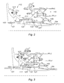
- the figure 1 shows a motor 1 during assembly of which we see only the outer casings.
- This is a turbojet engine with double flow and double body such as the CFM56. It comprises a front blower 3 and a module 5, said first module, constituted by the HP high pressure body with its shaft, said first shaft. These elements are already assembled.
- said low pressure turbine module BP 7 said second module, the shaft 9, said second shaft, is already engaged in the HP body.
- the critical zone is located in zone 8 of the inter-tree level, whose visibility is zero.
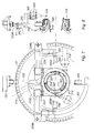
- the shaft 101, second shaft, of the second module, LP turbine is housed in the shaft 103, first shaft, of the first module, the HP body.
- the shaft 101 comprises at its end, on the right in the figure, a pin 104 for mounting a bearing.
- a radial flange 105 allows the assembly of the various elements constituting the LP turbine 110 partially visible.
- the shaft 103 of the HP body is extended by a pin 111 at its downstream end. There is a turbine portion 112 of the HP body only.
- the inter-shaft bearing 120 comprises an inner ring 121, fixed on the shaft 101 with the rolling elements, such as rollers 122, whose cage 122 'is crimped on the ring 121.
- the outer ring 123 is mounted cold-tight inside the pin 111. It is locked in place by a nut 125.
- figure 3 shows the same elements after assembly. The assembly is carried out by translational displacement of the BP turbine module 110 with the shaft 101 to the left relative to the figure 2 after expansion of the journal together with the outer ring, by heating, the HP module being fixed. It is understood that due to low tolerances, the risk is high of a contact between the parts of the bearing. This hard contact can be the cause of scratches, grooves or chipping primers that are likely to lead to the failure of the bearing.
- the applicant company has developed a method and apparatus for secure mounting of the BP module in this environment.
- the apparatus 200 comprises a mobile frame 210, to which is suspended a heating means of the HP body pin. This set is represented on Figures 4, 5 and 6 in several positions.
- the frame 210 comprises a carriage 211, mounted on wheels, with a vertical frame 212.
- a bracket 220 is mounted on this frame provided with rails so as to be able to slide between a first low position, active or of use, shown on the figure 4 and a second high position, of withdrawal, which we see on the figure 6 .
- An inverted T-shaped support 230 is attached to the end of the horizontal arm 222 of the bracket 220.
- the support 230 comprises a vertical arm 232 fixed rigidly relative to the horizontal arm 222 of the bracket, and two horizontal branches 233 and 234. The latter are arranged to support two slides 233C and 234C each supporting one half of the annular heating device 300, 300A and 300B respectively, see figure 7 .
- the apparatus is represented in the active position on the figure 4 .
- the support 230 is in abutment against the flange 51 of the casing of the HP body module. From this position, the heating device is released by separating the two halves 300A and 300B which move parallel to the two branches 233 and 234 with their respective slider 233C and 234C. Once the heating device is open it is disengaged upwardly by controlling the sliding of the bracket 220 in the rails of the frame 212.
- the apparatus is shown in the upper position of folding on the figure 6 .
- the installation of the heating device is carried out in the reverse sequence.
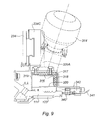
- the heating device is described in more detail in connection with the Figures 7, 8 and 9 .
- the figure 7 which is an enlarged view of the figure 4 shows the heating device with three heaters 310, 312 and 314, in dashed lines, arranged substantially tangentially to an annular enclosure 316 forming diffuser and air distributor. They are equidistant from each other and deliver a heated gas at a controlled temperature, in particular air, according to at least one tangential component.
- the heaters because of the bulk of the suspension can not be arranged strictly tangentially to the annular chamber 316.
- the latter is delimited by a cylindrical envelope 317 and two walls, 318 and 319, perpendicular to the axis of the motor.
- An inner cylindrical wall 320 is perforated and maintains a gap with the journal 111.
- the envelope comprises a thermally insulating material as seen on the walls 317 and 318.
- Deflectors 321 are disposed inside the annular enclosure between two consecutive heaters. These deflectors are arched and inclined towards the axis of the engine. The end receiving the gas flow of an adjacent heater is at a greater distance from the axis than the other end. In this way the gas flows opening into the chamber are both driven in a rotational movement about the axis of the engine with a centripetal component towards the perforated wall 320.
- the wall 318 of the end side of the pin comes into contact with the latter.
- the wall 319 on the other side provides a space or openings for gas leakage that will heat the thicker mass at this point of the trunnion.
- the elements of the envelope 317, 318, 319 defining the annular enclosure 316 are in two parts attached to their respective support 320A and B. These supports themselves are suspended from a slide, 233C and 234C respectively.
- the support 230 bears against the flange 51 by stops, one of which is visible on the figure 8 . This is the stop 232B secured to the vertical arm 232 of the support.
- the arms 233 and 234 also comprise setting means 234B and 233B that can be seen on the figure 7 .
- the wedges are retractable and are positioned behind the flange 51 to ensure the immobilization of the support on the flange 51.
- the device serves to support three thermocouples 340 distributed equidistant from each other.
- the figure 9 is a partial sectional view of the heating device 300 at one of the thermocouples 340. It is in abutment against the downstream surface of the pin to sense the temperature.
- a cable 341 connects the sensor to the control center which includes the function including controlling the heaters as a function of the temperature to be reached.
- the thermocouple is attached to the wall 318 by means of a bracket 342.
- the device also supports three members 350 for measuring the distance between the pin 111 and the LP shaft inside the latter. They are distributed equidistant from each other, for example at 3 hours, 6 hours and 9 hours, in rear view of the engine. Alignment of the LP shaft is performed by comparing the differences in the distances measured on these three points and by acting correlatively on the transverse positioning of the shaft in the handling system.
- the distance measuring members 350 are of the laser type, for example. They have been schematically represented on Figures 7 and 8 . They are mounted on support arms 351 fixed on the horizontal arms of the supports 230. They are movable between two positions as it appears on the figure 8 which shows a measuring device positioned at the top of the axis of the motor.
- a control console is mounted on the frame. It receives signals from temperature sensors as well as distance measurements. It also includes means for providing warning signals of the type for example green light red light to inform the operator of the situation and the state of preparation of the landing before docking.
- the assembly is completed by final berthing.
- the device of the invention gives all the simultaneous control of two major mounting conditions to ensure assembly of the bearing without risk.
- the invention is not limited to mounting the LP turbine module in an HP body of a gas turbine engine. It applies to all equivalent situations of mounting a second module assembled by a bearing in a first module.
Landscapes
- Engineering & Computer Science (AREA)
- Mechanical Engineering (AREA)
- General Engineering & Computer Science (AREA)
- Chemical & Material Sciences (AREA)
- Combustion & Propulsion (AREA)
- Turbine Rotor Nozzle Sealing (AREA)
- Structures Of Non-Positive Displacement Pumps (AREA)
- Support Of The Bearing (AREA)
Applications Claiming Priority (1)
| Application Number | Priority Date | Filing Date | Title |
|---|---|---|---|
| FR0552577A FR2890110B1 (fr) | 2005-08-26 | 2005-08-26 | Procede d'assemblage d'une turbomachine |
Publications (2)
| Publication Number | Publication Date |
|---|---|
| EP1757777A1 EP1757777A1 (fr) | 2007-02-28 |
| EP1757777B1 true EP1757777B1 (fr) | 2008-10-15 |
Family
ID=36354013
Family Applications (1)
| Application Number | Title | Priority Date | Filing Date |
|---|---|---|---|
| EP06119569A Active EP1757777B1 (fr) | 2005-08-26 | 2006-08-25 | Procédé d'assemblage d'une turbomachine |
Country Status (7)
| Country | Link |
|---|---|
| US (1) | US7594324B2 (enExample) |
| EP (1) | EP1757777B1 (enExample) |
| JP (1) | JP4861770B2 (enExample) |
| CA (1) | CA2557104C (enExample) |
| DE (1) | DE602006003149D1 (enExample) |
| FR (1) | FR2890110B1 (enExample) |
| RU (1) | RU2415275C2 (enExample) |
Families Citing this family (25)
| Publication number | Priority date | Publication date | Assignee | Title |
|---|---|---|---|---|
| FR2889981B1 (fr) | 2005-08-26 | 2007-11-02 | Snecma | Dispositif de chauffage d'une piece cylindrique, utilisation dans l'assemblage d'un palier inter-arbres dans une turbomachine. |
| US8347500B2 (en) * | 2008-11-28 | 2013-01-08 | Pratt & Whitney Canada Corp. | Method of assembly and disassembly of a gas turbine mid turbine frame |
| US20100132377A1 (en) * | 2008-11-28 | 2010-06-03 | Pratt & Whitney Canada Corp. | Fabricated itd-strut and vane ring for gas turbine engine |
| US8061969B2 (en) * | 2008-11-28 | 2011-11-22 | Pratt & Whitney Canada Corp. | Mid turbine frame system for gas turbine engine |
| US8091371B2 (en) * | 2008-11-28 | 2012-01-10 | Pratt & Whitney Canada Corp. | Mid turbine frame for gas turbine engine |
| US8099962B2 (en) * | 2008-11-28 | 2012-01-24 | Pratt & Whitney Canada Corp. | Mid turbine frame system and radial locator for radially centering a bearing for gas turbine engine |
| US20100132371A1 (en) * | 2008-11-28 | 2010-06-03 | Pratt & Whitney Canada Corp. | Mid turbine frame system for gas turbine engine |
| US8245518B2 (en) * | 2008-11-28 | 2012-08-21 | Pratt & Whitney Canada Corp. | Mid turbine frame system for gas turbine engine |
| US8347635B2 (en) * | 2008-11-28 | 2013-01-08 | Pratt & Whitey Canada Corp. | Locking apparatus for a radial locator for gas turbine engine mid turbine frame |
| FR2944558B1 (fr) * | 2009-04-17 | 2014-05-02 | Snecma | Moteur a turbine a gaz double corps pourvu d'un palier de turbine bp supplementaire. |
| CN102330605B (zh) * | 2011-09-05 | 2013-06-26 | 沈阳黎明航空发动机(集团)有限责任公司 | 一种转子与前后支承组合装配的重型燃机装配方法 |
| FR2990239B1 (fr) * | 2012-05-02 | 2015-10-30 | Snecma | Procede de devissage avant d'un ecrou de liaison dans un turboreacteur a double corps, outillage de devissage |
| FR2990238B1 (fr) * | 2012-05-02 | 2015-10-30 | Snecma | Procede de devissage arriere d'un ecrou de liaison dans un turboreacteur a double corps, outillage de devissage |
| FR2990242B1 (fr) | 2012-05-02 | 2014-06-13 | Snecma | Procede de demontage d'un turboreacteur |
| FR3024493B1 (fr) * | 2014-07-29 | 2019-04-19 | Safran Aircraft Engines | Element de turbomachine comprenant un joint d'etancheite entre un stator et un rotor, et procede de montage |
| FR3024492B1 (fr) | 2014-07-29 | 2019-08-23 | Safran Aircraft Engines | Element comprenant un stator et un rotor de turbomachine avec un joint d'etancheite et test de ce joint |
| WO2016198216A1 (en) * | 2015-05-07 | 2016-12-15 | Nuovo Pignone Tecnologie Srl | Assembly/disassembly apparatus for flanged mechanical device and assembly/disassembly method for flanged mechanical devices |
| RU2659694C2 (ru) * | 2016-12-28 | 2018-07-03 | Акционерное общество "ОДК-Авиадвигатель" | Силовая свободная турбина |
| FR3068078B1 (fr) | 2017-06-27 | 2021-06-25 | Safran Aircraft Engines | Dispositif et procede pour l'assemblage d'une turbomachine |
| FR3068390B1 (fr) * | 2017-06-28 | 2019-07-19 | Safran Aircraft Engines | Dispositif pour l'assemblage d'une turbomachine, et procede utilisant le dispositif |
| FR3072137B1 (fr) * | 2017-10-06 | 2020-07-24 | Safran Aircraft Engines | Dispositif pour l'assemblage d'une turbomachine, et procede utilisant le dispositif |
| CN109268211B (zh) * | 2018-11-29 | 2019-10-11 | 河北思达歌数据科技投资有限公司 | 一种自适应风力发电装置 |
| CN109209786B (zh) * | 2018-11-29 | 2019-10-29 | 绍兴市亚索新能源科技有限公司 | 一种风力发电机组故障检测方法 |
| CN111946460B (zh) * | 2020-08-10 | 2022-08-05 | 中国人民解放军第五七一九工厂 | 用于航空发动机风扇组合件装配的导正装置及装配方法 |
| CN115415786A (zh) * | 2022-08-30 | 2022-12-02 | 北京动力机械研究所 | 一种人机协同的涡扇发动机核心机装配系统与装配方法 |
Family Cites Families (18)
| Publication number | Priority date | Publication date | Assignee | Title |
|---|---|---|---|---|
| US2756561A (en) * | 1952-01-18 | 1956-07-31 | Rolls Royce | Gas turbine engine with axial-flow compressor and bearing means for supporting the compressor rotor |
| US2862356A (en) * | 1954-07-16 | 1958-12-02 | Rolls Royce | Bearing arrangements for gas-turbine engines |
| US3909085A (en) * | 1973-09-08 | 1975-09-30 | Rolls Royce 1971 Ltd | Preloaded bearings |
| SU549307A1 (ru) * | 1975-06-20 | 1977-03-05 | Украинский Заочный Политехнический Институт | Способ соединени деталей типа вал-втулка |
| US4167809A (en) * | 1977-11-10 | 1979-09-18 | General Motors Corporation | Hot air arbor extractor |
| US4283096A (en) * | 1978-04-21 | 1981-08-11 | United Technologies Corporation | Intershaft bearing |
| FR2515734A1 (fr) * | 1981-11-05 | 1983-05-06 | Snecma | Systeme d'ajustement du centrage d'une roue de turbomachine et turbomachine munie de moyens permettant l'application dudit systeme |
| FR2518650B1 (fr) * | 1981-12-22 | 1986-05-30 | Snecma | Dispositif de pilotage des jeux d'un palier inter-arbres de turbomachine multi-corps |
| US4685286A (en) * | 1984-05-02 | 1987-08-11 | United Technologies Corporation | Method of disassembly for a gas turbine engine |
| GB2177160A (en) * | 1985-07-04 | 1987-01-14 | Prime Mover Maintenance Limite | Servicing gas turbines |
| FR2644843B1 (fr) * | 1989-03-23 | 1991-05-24 | Snecma | Procede de montage de la turbine basse pression sur le corps haute pression d'une turbomachine a palier inter-arbres et outillages pour la mise en oeuvre du procede |
| US5201796A (en) * | 1991-10-15 | 1993-04-13 | United Technologies Corporation | Gas turbine engine arrangement |
| US6491497B1 (en) * | 2000-09-22 | 2002-12-10 | General Electric Company | Method and apparatus for supporting rotor assemblies during unbalances |
| JP2002303157A (ja) * | 2001-04-05 | 2002-10-18 | Ishikawajima Harima Heavy Ind Co Ltd | 差動軸受構造 |
| EP1310323B1 (de) * | 2001-11-12 | 2011-03-30 | Franz Haimer Maschinenbau KG | Schrumpfvorrichtung für einen Werkzeughalter |
| US6910863B2 (en) * | 2002-12-11 | 2005-06-28 | General Electric Company | Methods and apparatus for assembling a bearing assembly |
| FR2857708B1 (fr) * | 2003-07-15 | 2005-09-23 | Snecma Moteurs | Dispositif perfectionne de fixation d'un arbre de moteur sur un support de palier |
| FR2858649B1 (fr) * | 2003-08-05 | 2005-09-23 | Snecma Moteurs | Turbine basse-pression de turbomachine |
-
2005
- 2005-08-26 FR FR0552577A patent/FR2890110B1/fr not_active Expired - Fee Related
-
2006
- 2006-08-23 CA CA2557104A patent/CA2557104C/fr active Active
- 2006-08-23 US US11/466,652 patent/US7594324B2/en active Active
- 2006-08-24 JP JP2006227434A patent/JP4861770B2/ja active Active
- 2006-08-25 DE DE602006003149T patent/DE602006003149D1/de active Active
- 2006-08-25 EP EP06119569A patent/EP1757777B1/fr active Active
- 2006-08-25 RU RU2006130730/06A patent/RU2415275C2/ru active
Also Published As
| Publication number | Publication date |
|---|---|
| RU2415275C2 (ru) | 2011-03-27 |
| JP4861770B2 (ja) | 2012-01-25 |
| US20070044307A1 (en) | 2007-03-01 |
| EP1757777A1 (fr) | 2007-02-28 |
| FR2890110B1 (fr) | 2007-11-02 |
| RU2006130730A (ru) | 2008-02-27 |
| CA2557104C (fr) | 2014-05-20 |
| FR2890110A1 (fr) | 2007-03-02 |
| JP2007064216A (ja) | 2007-03-15 |
| DE602006003149D1 (de) | 2008-11-27 |
| US7594324B2 (en) | 2009-09-29 |
| CA2557104A1 (fr) | 2007-02-26 |
Similar Documents
| Publication | Publication Date | Title |
|---|---|---|
| EP1757777B1 (fr) | Procédé d'assemblage d'une turbomachine | |
| EP1758429B1 (fr) | Dispositif de chauffage d'une pièce cylindrique. Utilisation dans l'assemblage d'un palier inter-arbres dans une turbomachine | |
| CA2582401C (fr) | Dispositif de fixation de secteurs d'anneau autour d'une roue de turbine d'une turbomachine | |
| EP1847686B1 (fr) | Dispositif de fixation de secteurs d'anneau sur un carter de turbine d'une turbomachine | |
| CA2772763C (fr) | Dispositif de support d'un anneau de turbine, turbine avec un tel dispositif et turbomoteur avec une telle turbine | |
| EP3645847B1 (fr) | Procédé d'assemblage d'une turbomachine | |
| EP1916391B1 (fr) | Méthode et dispositif pour réduire la vitesse en cas de rupture d'arbre de turbine de moteur à turbine à gaz | |
| EP2844847B1 (fr) | Outillage et procede de devissage avant d'un ecrou de liaison dans un turboreacteur a double corps | |
| FR2522067A1 (fr) | Carter de compresseur | |
| EP3698022A1 (fr) | Dispositif et procede de refroidissement d'une turbine basse pression dans une turbomachine | |
| FR3068390B1 (fr) | Dispositif pour l'assemblage d'une turbomachine, et procede utilisant le dispositif | |
| FR2961850A1 (fr) | Turbine pour une turbomachine, telle qu'un turboreacteur ou un turbopropulseur d'avion | |
| FR3036735A1 (fr) | Veine instrumentee de turbomachine | |
| FR3069632B1 (fr) | Dispositif de mesure de l'expansion axiale ou radiale d'un organe tubulaire de turbomachine | |
| EP3891364B1 (fr) | Procédé de refroidissement d'un carter de turbine pour une turbomachine | |
| FR3021742A1 (fr) | Veine instrumentee de turbomachine | |
| FR2915511A1 (fr) | Limitation de survitesse du rotor d'une turbine de turbomachine | |
| FR3089006A1 (fr) | Dispositif de mesure de temperature et son procede de montage dans une turbomachine d’aeronef |
Legal Events
| Date | Code | Title | Description |
|---|---|---|---|
| PUAI | Public reference made under article 153(3) epc to a published international application that has entered the european phase |
Free format text: ORIGINAL CODE: 0009012 |
|
| 17P | Request for examination filed |
Effective date: 20060825 |
|
| AK | Designated contracting states |
Kind code of ref document: A1 Designated state(s): AT BE BG CH CY CZ DE DK EE ES FI FR GB GR HU IE IS IT LI LT LU LV MC NL PL PT RO SE SI SK TR |
|
| AX | Request for extension of the european patent |
Extension state: AL BA HR MK YU |
|
| AKX | Designation fees paid |
Designated state(s): DE FR GB |
|
| GRAP | Despatch of communication of intention to grant a patent |
Free format text: ORIGINAL CODE: EPIDOSNIGR1 |
|
| GRAS | Grant fee paid |
Free format text: ORIGINAL CODE: EPIDOSNIGR3 |
|
| GRAA | (expected) grant |
Free format text: ORIGINAL CODE: 0009210 |
|
| AK | Designated contracting states |
Kind code of ref document: B1 Designated state(s): DE FR GB |
|
| REG | Reference to a national code |
Ref country code: GB Ref legal event code: FG4D Free format text: NOT ENGLISH |
|
| REF | Corresponds to: |
Ref document number: 602006003149 Country of ref document: DE Date of ref document: 20081127 Kind code of ref document: P |
|
| PLBE | No opposition filed within time limit |
Free format text: ORIGINAL CODE: 0009261 |
|
| STAA | Information on the status of an ep patent application or granted ep patent |
Free format text: STATUS: NO OPPOSITION FILED WITHIN TIME LIMIT |
|
| 26N | No opposition filed |
Effective date: 20090716 |
|
| REG | Reference to a national code |
Ref country code: FR Ref legal event code: PLFP Year of fee payment: 10 |
|
| REG | Reference to a national code |
Ref country code: FR Ref legal event code: PLFP Year of fee payment: 11 |
|
| REG | Reference to a national code |
Ref country code: FR Ref legal event code: PLFP Year of fee payment: 12 |
|
| REG | Reference to a national code |
Ref country code: FR Ref legal event code: CD Owner name: SAFRAN AIRCRAFT ENGINES Effective date: 20170713 |
|
| REG | Reference to a national code |
Ref country code: FR Ref legal event code: PLFP Year of fee payment: 13 |
|
| PGFP | Annual fee paid to national office [announced via postgrant information from national office to epo] |
Ref country code: DE Payment date: 20250819 Year of fee payment: 20 |
|
| PGFP | Annual fee paid to national office [announced via postgrant information from national office to epo] |
Ref country code: GB Payment date: 20250825 Year of fee payment: 20 |
|
| PGFP | Annual fee paid to national office [announced via postgrant information from national office to epo] |
Ref country code: FR Payment date: 20250827 Year of fee payment: 20 |