EP1757476A1 - Procédé et dispositif de contrôle d'un système de climatisation d'habitâcle de véhicule - Google Patents
Procédé et dispositif de contrôle d'un système de climatisation d'habitâcle de véhicule Download PDFInfo
- Publication number
- EP1757476A1 EP1757476A1 EP06015336A EP06015336A EP1757476A1 EP 1757476 A1 EP1757476 A1 EP 1757476A1 EP 06015336 A EP06015336 A EP 06015336A EP 06015336 A EP06015336 A EP 06015336A EP 1757476 A1 EP1757476 A1 EP 1757476A1
- Authority
- EP
- European Patent Office
- Prior art keywords
- interior
- determined
- temperature
- vehicle
- measuring point
- Prior art date
- Legal status (The legal status is an assumption and is not a legal conclusion. Google has not performed a legal analysis and makes no representation as to the accuracy of the status listed.)
- Granted
Links
Images

Classifications
-
- B—PERFORMING OPERATIONS; TRANSPORTING
- B60—VEHICLES IN GENERAL
- B60H—ARRANGEMENTS OF HEATING, COOLING, VENTILATING OR OTHER AIR-TREATING DEVICES SPECIALLY ADAPTED FOR PASSENGER OR GOODS SPACES OF VEHICLES
- B60H1/00—Heating, cooling or ventilating [HVAC] devices
- B60H1/00642—Control systems or circuits; Control members or indication devices for heating, cooling or ventilating devices
- B60H1/00735—Control systems or circuits characterised by their input, i.e. by the detection, measurement or calculation of particular conditions, e.g. signal treatment, dynamic models
-
- B—PERFORMING OPERATIONS; TRANSPORTING
- B60—VEHICLES IN GENERAL
- B60H—ARRANGEMENTS OF HEATING, COOLING, VENTILATING OR OTHER AIR-TREATING DEVICES SPECIALLY ADAPTED FOR PASSENGER OR GOODS SPACES OF VEHICLES
- B60H1/00—Heating, cooling or ventilating [HVAC] devices
- B60H1/00642—Control systems or circuits; Control members or indication devices for heating, cooling or ventilating devices
- B60H1/0073—Control systems or circuits characterised by particular algorithms or computational models, e.g. fuzzy logic or dynamic models
-
- B—PERFORMING OPERATIONS; TRANSPORTING
- B60—VEHICLES IN GENERAL
- B60H—ARRANGEMENTS OF HEATING, COOLING, VENTILATING OR OTHER AIR-TREATING DEVICES SPECIALLY ADAPTED FOR PASSENGER OR GOODS SPACES OF VEHICLES
- B60H1/00—Heating, cooling or ventilating [HVAC] devices
- B60H1/00642—Control systems or circuits; Control members or indication devices for heating, cooling or ventilating devices
- B60H1/00735—Control systems or circuits characterised by their input, i.e. by the detection, measurement or calculation of particular conditions, e.g. signal treatment, dynamic models
- B60H1/00807—Control systems or circuits characterised by their input, i.e. by the detection, measurement or calculation of particular conditions, e.g. signal treatment, dynamic models the input being a specific way of measuring or calculating an air or coolant temperature
Definitions
- the invention relates to a method and a device for controlling an air conditioning system for an interior of a vehicle.
- an air conditioning system In order to improve the interior comfort and the thermal comfort in a vehicle, an air conditioning system is generally used, which is also referred to as air conditioning and usually consists of at least a heating and refrigerant circuit, an air conditioner and an air duct.
- Fully automatic or semi-automatic vehicle air conditioning systems are usually based on interior temperature control.
- the temperature control is carried out by comparing a temperature setpoint with a measured representative interior temperature. The difference between the two values is fed to an interior temperature controller, the manipulated variable of which leads to further subordinate control circuits for heating heat exchanger temperature, outlet temperature or evaporator temperature.
- a direct control of the corresponding actuators on the manipulated variable of the interior temperature controller is also possible.
- the positioning of the indoor temperature sensor or sensor is problematic because a single sensor location can not provide optimal signals for all operating points.
- at low outside temperatures is a rather deep, fußraumlastige arrangement of the interior temperature sensor advantageous, whereas at high ambient temperatures due to the human temperature perception of the headspace temperature is given greater importance.
- two interior temperature sensors are used, for example one in the center console area, which is usually integrated in the climate control unit, and one in the region of a headliner.
- the two detected interior temperature sensor signals are weighted depending on the situation and processed to a resulting interior temperature signal, the transitions between different weights are usually continuous.
- interior temperature sensors are technically complex components. This results in high costs.
- a sensor ventilation is normally required, for example by means of a sensor blower. Such has a high failure rate and is an additional source of noise. Forced ventilation creates a high degree of contamination of the sensor. Due to the ventilation requirement, the possibilities for shaping are limited.
- the US 2002/0125334 A1 describes another alternative solution in which the real indoor temperature sensor is replaced by a virtual one.
- the virtual interior temperature is determined via a thermodynamic interior temperature model for the interior temperature distribution.
- the interior temperature model is parameterized via vehicle data such as glass surfaces, body structure, interior materials and subjected to external and internal influencing variables, so that based on a starting value of the time profile of the interior temperature can be determined, the starting value for the interior temperature is usually via a simple temperature sensor on the circuit board of climate control unit determined.
- a vehicle speed, an outside temperature, the solar heat radiation, an outlet temperature of an outflow opening, an air outlet speed or an air volume setting and an air distribution setting are used. It is also proposed to use two virtual indoor temperature sensors, one located in the foot area and one in the head area.
- the invention is therefore based on the object of specifying an improved method and an improved device of the type mentioned above, which allow a regulation of the air conditioning system adapted to the respective situation.
- the object is achieved by a method which has the features specified in claim 1, and by a device having the features specified in claim 12.
- the known model-based interior temperature control can be significantly improved by first determining ambient and vehicle conditions, on the basis of which a location for a virtual measurement point in the interior of the vehicle is determined, by means of a thermodynamic model for the interior representing the virtual measurement point of the interior space interior temperature as Control variable is determined.
- the comfort for occupants of the vehicle is increased by a more pleasant temperature and air conditioning.
- the comfort gain is achieved procedurally, for example, by an appropriate software module, without additional costs, additional weight and additional space.
- the virtual measuring point in the interior of the vehicle can be continuously determined and changed as a function of the ambient and / or vehicle conditions. In other words, the modeled virtual measuring point for the interior temperature can "wander" through the vehicle interior.
- the location of the virtual measuring point with respect to a vertical is preferably determined as a function of an outside temperature, in particular of the vehicle ambient temperature.
- an outside temperature in particular of the vehicle ambient temperature.
- the vertical temperature gradient of warm and cold air as a function of the outside temperature acting on the vehicle interior is taken into account.
- the location of the virtual measuring point at low outside temperature in a foot region of the interior and at high outside temperature in a head region of the interior is advantageously determined. In this way, the climate in the interior is comfortably controlled even in extreme situations.
- an area within which the location of the virtual measuring point is determined can be predetermined. Unfavorable locations for the virtual measuring point can thereby be excluded.
- the method can be influenced in this way by a user in his sense.
- Improved comfort is achieved by determining or specifying the location of the virtual measurement point in an area of a seat.
- a driver or other occupant may specify that the virtual measurement point is placed in the area of his seat.
- an occupied seat is advantageously first determined or predetermined, and then the location of the virtual measuring point in the area of the ascertained seat is determined. Unoccupied seats are not taken into account in this way.
- the location for the virtual measuring point is redetermined when the ambient and vehicle conditions change. This allows continuous adjustment of the temperature control to the current ambient and vehicle conditions. Jump-shaped changes can be avoided.
- the indoor temperature signals of the plurality of virtual measuring points are weighted depending on the situation. Additionally or alternatively, the associated virtually determined interior temperature signals can be averaged.
- the weighting factor or degree for the weighting can be predetermined, for example, by a user or depending on the situation.
- an outside temperature and / or the intensity of the solar radiation are expediently taken into account and specified.
- Corresponding measurement signals can be detected by means of associated sensors.
- the vehicle condition is preferably the own and current vehicle speed and / or an exit temperature of a flow outlet opening of the air conditioning system and / or an air outlet speed and / or an air distribution setting and / or data of glass surfaces and / or data of the body shape or structure and / or data of interior materials considered and used.
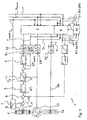
- FIG. 1 shows a device 1 for controlling an air conditioning system for an interior 2 of a vehicle, not shown, as a block diagram.
- the device 1 has an interior temperature controller 3 and an outlet temperature controller 4 which is subordinate to this.
- the interior temperature controller 3 is a control error .DELTA.T I for the interior temperature T I is supplied.
- a user Via an internal temperature selector device 5, a user can set a desired interior temperature T I_W .
- the desired baumraumtemperetur T I_W based on the current outdoor temperature T A to the indoor temperature setpoint T I_Soll be corrected.
- a correction module 6 is provided.
- the metrologically detected outside temperature T A can be corrected based on a characteristic curve of a characteristic module 7.
- the interior temperature setpoint T I_Soll is clearly indicated at low outside temperatures T A.
- a virtual interior temperature actual value T I_virtually is fed to a difference module 8 .
- the virtual Certainlyraumtemperatur_Istwert T I_vlrtuell is virtually determined using a simulation module 9.
- the interior temperature T I is determined virtually by means of the simulation module 9 for a virtual measuring point at a location X ⁇ of the interior 2 to be determined or predetermined using a thermodynamic interior temperature model for the interior temperature distribution .
- the location X ⁇ of the virtual measuring point in the interior 2 of the vehicle is first determined.
- the location X ⁇ of the virtual measurement point is determined by a localization module 10 based on vehicle conditions F1 to Fn and environmental conditions U1 to Um, z. B. on the basis of the outlet temperature T outlet at a flow outlet opening of an air distribution system not shown, air distribution information D, the fan speed n, vehicle ambient or outdoor temperature T A , the intensity of solar radiation I sun and the vehicle speed v, determined depending on the situation and continuously updated and adapted.
- the virtual measuring point moves through the interior 2 in such a way that it largely meets the current conditions.
- the localization module 10 In order to avoid sudden changes in the behavior of the air conditioning system, the localization module 10 only performs slow movements of the location in the event of changes in the current vehicle or ambient conditions F1 to Fn, U1 to Um of the virtual indoor temperature sensor.
- the determined location X ⁇ for the virtual measuring point is then supplied to the simulation module 9 for determining the virtual interior temperature actual value T l_virtuell . It is based on the thermodynamic interior temperature model taking into account the vehicle conditions F1 to Fn, z. B. the outlet temperature T outlet at an outflow, of air distribution information D, the fan speed n, and / or the environmental conditions U1 to Um, z. B. the vehicle exterior temperature T A , the intensity of the sun I sun , the own vehicle speed v, by means of the simulation module 9 at the location X ⁇ the virtual indoor temperature actual value T l_virtuell determined.
- the thermodynamic interior temperature model takes into account vehicle data, such.
- the simulation module 9 determines the respective virtual value of the interior temperature T I_virtually at the location .
- the starting value can be over a not shown temperature sensor can be determined or specified manually. It can also be assumed as start value that the interior temperature T I is equal to the outside temperature T A.
- the virtually determined interior temperature actual value T I_virtuell is then used to determine the control deviation ⁇ T I for the interior temperature T I based on the difference between the internal temperature setpoint T I_Soll and the virtual interior temperature actual value T I_virtuell .
- the control deviation .DELTA.T I is the interior temperature controller 3, for example, a P-controller supplied, which forms a control variable U.
- the manipulated variable U of the interior temperature controller 3 is converted into a reference variable F for an outlet temperature controller 4 by means of a characteristic module 11 on the basis of characteristic curves C T.
- the evaluation of the characteristic curves C T takes into account, based on an air distribution information D, which flow outlet opening LA is activated, ie is open, and which associated temperature sensor S T is relevant for the outlet temperature T outlet at the respective flow outlet opening LA.
- the upper of the indicated characteristic curves C T is an outlet temperature T outlet at a flow outlet opening LA in the footwell, the lower of an outlet temperature T outlet at a flow outlet opening LA in the aeration level.
- the control difference ⁇ T outlet from target outlet temperature and actual outlet temperature T outlet is supplied to the designed as a PI controller outlet temperature controller 4, whose control signal S controls the temperature mixing flap 12 of an air conditioner.
- a PI controller outlet temperature controller 4 whose control signal S controls the temperature mixing flap 12 of an air conditioner.
- the manually specified air distribution information D is supplied to the simulation module 9 and the localization module 10.
- the automatically prepared air distribution information D is supplied to these modules 9 and 10 in the same way.
- a blower intensity setting Gs which is adjustable at a blower setting device 14 for manually setting a rotational speed n of an air conditioning blower 15 is taken into account in the determination of the interior temperature T I (semi-automatic air conditioning, FIG. 1).
- the fan speed n is supplied in the same way to the modules 9 and 10.
- FIG. 2 shows a schematic representation of an exemplary distribution of possible locations X ⁇ for a virtual measuring point in an interior 2 of a vehicle 16 in order to illustrate the mode of operation of the localization module 10.
- the location X ⁇ of the virtual measuring point is determined with respect to a vertical temperature gradient as a function of the outside temperature T A such that at low outside temperature T A, the location X ⁇ in a foot region of the interior 2 and at high outside temperature T A location X ⁇ in a head region of the interior. 2 lies.
- T A outside temperature
- T A the location X ⁇ in a foot region of the interior 2
- T A location X ⁇ in a head region of the interior. 2 lies.
- the potential locations X ⁇ of the virtual measuring point can be limited in this way in order to influence the regulation of the automatic climate control in a targeted manner.
- the area of the potential locations X ⁇ can be limited to a lower, rear area of the interior 2, in order to optimally air-condition the area around a child sitting there, thus preventing hypothermia of the child due to the generally cooler temperature in the lower area of the interior 2 ,
- Another possibility is the possible places generally confined to one area of a seat. This can be done automatically or manually happen. In the automatic case, an occupied seat is expediently automatically determined for the assignment.
- the localization module 10 may be configured such that a plurality of virtual measurement points movable in the interior are determined at locations X ⁇ i and separate interior temperatures T l_virtually determined for each of these virtual measurement points.
- the virtual interior temperatures T l_virtuell of the virtual measuring points can additionally be weighted depending on the situation and / or position.
- a differentiated air conditioning of individual zones can be achieved, wherein the respective zone is air-conditioned as a function of the virtual interior temperature T I_ determined for this area.
- individual virtually determined interior temperature actual values T I_virtuell can be used for a separate zone-related regulation of the interior temperature T I.
- several areas for the possible locations X ⁇ i of the multiple virtual measurement points can be limited to one seat each. For example, it can be monitored whether a seat is occupied or unoccupied. If a seat is occupied, several places X ⁇ are determined for this seat for the air conditioning of the seat area.
Landscapes
- Physics & Mathematics (AREA)
- Engineering & Computer Science (AREA)
- Thermal Sciences (AREA)
- Mechanical Engineering (AREA)
- Fuzzy Systems (AREA)
- Mathematical Physics (AREA)
- Software Systems (AREA)
- Theoretical Computer Science (AREA)
- Air-Conditioning For Vehicles (AREA)
- Air Conditioning Control Device (AREA)
Applications Claiming Priority (1)
| Application Number | Priority Date | Filing Date | Title |
|---|---|---|---|
| DE102005040377A DE102005040377A1 (de) | 2005-08-25 | 2005-08-25 | Verfahren und Vorrichtung zur Regelung eines Klimatisierungssystems für einen Innenraum eines Fahrzeugs |
Publications (2)
| Publication Number | Publication Date |
|---|---|
| EP1757476A1 true EP1757476A1 (fr) | 2007-02-28 |
| EP1757476B1 EP1757476B1 (fr) | 2008-06-18 |
Family
ID=37091547
Family Applications (1)
| Application Number | Title | Priority Date | Filing Date |
|---|---|---|---|
| EP06015336A Not-in-force EP1757476B1 (fr) | 2005-08-25 | 2006-07-24 | Procédé et dispositif de contrôle d'un système de climatisation d'habitacle de véhicule |
Country Status (3)
| Country | Link |
|---|---|
| EP (1) | EP1757476B1 (fr) |
| AT (1) | ATE398538T1 (fr) |
| DE (2) | DE102005040377A1 (fr) |
Cited By (2)
| Publication number | Priority date | Publication date | Assignee | Title |
|---|---|---|---|---|
| FR2993641A1 (fr) * | 2012-07-23 | 2014-01-24 | Peugeot Citroen Automobiles Sa | Dispositif d'estimation indirecte de la temperature dans une enceinte alimentee en air traite par une installation de chauffage/climatisation |
| EP2009358A3 (fr) * | 2007-06-30 | 2014-09-24 | Robert Bosch Gmbh | Procédé de régulation prédictif basé sur un modèle de bâtiment destiné à chauffer un système limité |
Families Citing this family (1)
| Publication number | Priority date | Publication date | Assignee | Title |
|---|---|---|---|---|
| EP2221198A1 (fr) | 2009-02-12 | 2010-08-25 | Behr-Hella Thermocontrol GmbH | Procédé de détermination de la valeur de température de départ d'un controle de la température d'habitacle basé sur un modèle du véhicule |
Citations (4)
| Publication number | Priority date | Publication date | Assignee | Title |
|---|---|---|---|---|
| EP0612964A1 (fr) * | 1993-02-24 | 1994-08-31 | Gec Alsthom Transport Sa | Dispositif de régulation de climatisation |
| EP0968855A1 (fr) * | 1998-06-04 | 2000-01-05 | Sanden Corporation | Appareil de conditionnement pour véhicule |
| US20020125334A1 (en) | 2000-03-07 | 2002-09-12 | Bernard Remond | Regulation of the temperature, the speed and the distribution of the air blown into a motor-vehicle passenger compartment |
| US20030146290A1 (en) * | 2002-02-04 | 2003-08-07 | Mingyu Wang | Model-based method of generating control algorithms for an automatic climate control system |
Family Cites Families (1)
| Publication number | Priority date | Publication date | Assignee | Title |
|---|---|---|---|---|
| DE3843898A1 (de) * | 1988-12-24 | 1990-06-28 | Porsche Ag | Klimatisierungssystem fuer ein fahrzeug |
-
2005
- 2005-08-25 DE DE102005040377A patent/DE102005040377A1/de not_active Withdrawn
-
2006
- 2006-07-24 EP EP06015336A patent/EP1757476B1/fr not_active Not-in-force
- 2006-07-24 DE DE502006000938T patent/DE502006000938D1/de active Active
- 2006-07-24 AT AT06015336T patent/ATE398538T1/de not_active IP Right Cessation
Patent Citations (4)
| Publication number | Priority date | Publication date | Assignee | Title |
|---|---|---|---|---|
| EP0612964A1 (fr) * | 1993-02-24 | 1994-08-31 | Gec Alsthom Transport Sa | Dispositif de régulation de climatisation |
| EP0968855A1 (fr) * | 1998-06-04 | 2000-01-05 | Sanden Corporation | Appareil de conditionnement pour véhicule |
| US20020125334A1 (en) | 2000-03-07 | 2002-09-12 | Bernard Remond | Regulation of the temperature, the speed and the distribution of the air blown into a motor-vehicle passenger compartment |
| US20030146290A1 (en) * | 2002-02-04 | 2003-08-07 | Mingyu Wang | Model-based method of generating control algorithms for an automatic climate control system |
Cited By (3)
| Publication number | Priority date | Publication date | Assignee | Title |
|---|---|---|---|---|
| EP2009358A3 (fr) * | 2007-06-30 | 2014-09-24 | Robert Bosch Gmbh | Procédé de régulation prédictif basé sur un modèle de bâtiment destiné à chauffer un système limité |
| FR2993641A1 (fr) * | 2012-07-23 | 2014-01-24 | Peugeot Citroen Automobiles Sa | Dispositif d'estimation indirecte de la temperature dans une enceinte alimentee en air traite par une installation de chauffage/climatisation |
| WO2014016485A1 (fr) * | 2012-07-23 | 2014-01-30 | Peugeot Citroen Automobiles Sa | Dispositif d'estimation indirecte de la température dans une enceinte alimentée en air traité par une installation de chauffage/climatisation |
Also Published As
| Publication number | Publication date |
|---|---|
| EP1757476B1 (fr) | 2008-06-18 |
| ATE398538T1 (de) | 2008-07-15 |
| DE102005040377A1 (de) | 2007-03-01 |
| DE502006000938D1 (de) | 2008-07-31 |
Similar Documents
| Publication | Publication Date | Title |
|---|---|---|
| EP0805056B1 (fr) | Conditionnement d'air pour véhicule avec dispositif pour diriger l'air, réglable en fonction du rayonnement solaire | |
| DE4113374C2 (de) | Verfahren und Vorrichtung zur Regelung einer Klimaanlage | |
| DE3409321C2 (fr) | ||
| DE19534078B4 (de) | Kraftfahrzeug-Klimaanlage | |
| DE102005002062A1 (de) | Verfahren zur Regelung von Luftdüsen zur Klimatisierung eines Kraftfahrzeugs | |
| DE10238552A1 (de) | System und Verfahren für die Klimaregelung in Fahrzeugen | |
| DE4119042A1 (de) | Regelungseinrichtung einer klimaanlage fuer fahrzeuge | |
| EP3269571B1 (fr) | Procédé de fonctionnement d'un système de climatisation d'un habitacle d'un véhicule automobile | |
| DE102017202872B4 (de) | Verfahren und Vorrichtung zur Bestimmung der Ausblastemperaturen einer automatischen Klimaanlage eines Fahrzeugs | |
| EP1757476B1 (fr) | Procédé et dispositif de contrôle d'un système de climatisation d'habitacle de véhicule | |
| DE19829143C1 (de) | Verfahren zur Änderung der Innenraumtemperatur eines Fahrzeuges | |
| DE102018128295A1 (de) | Verfahren zum steuern eines thermischen komfortsteuerungssystems für fahrgemeinschaftsfahrzeuge | |
| EP1236593B1 (fr) | Climatiseur et appareil pour régler le confort thermique dans un véhicule | |
| DE102008031695B4 (de) | Verfahren zur Klimatisierung eines Fahrzeugs | |
| WO2002009961A1 (fr) | Systeme de climatisation de vehicule | |
| EP0546429B1 (fr) | Méthode et dispositif de réglage automatique d'une installation de chauffage/climatisation dans une voiture automobile | |
| DE10324571B3 (de) | Fahrzeug-Heiz- und/oder Klimaanlage und Verfahren zur Heiz- und/oder Klimatisierungsregelung in Fahrzeugen | |
| WO2020043364A1 (fr) | Commande de clapets d'aération globale et entièrement variable | |
| DE102018207316A1 (de) | Fahrzeugklimasystem | |
| EP1270287B1 (fr) | Procédé de réglage de la température intérieure d'un habitacle de véhicule et dispositif de chauffage ou de climatisation pour véhicule | |
| DE102007033222B4 (de) | Verfahren und Vorrichtung zum Steuern oder Regeln einer Sitzheizung | |
| DE19948735A1 (de) | Verfahren und Einrichtung zur Klimatisierung von Fahrzeugsitzen | |
| DE102020105868A1 (de) | Verfahren zum Betrieb von Klimatisierungsanordnungen in einem Kraftfahrzeug und Kraftfahrzeug | |
| DE19946966C2 (de) | Verfahren zur Klimaregelung in einem Innenraum eines geschlossenen Objekts | |
| DE102017004997B4 (de) | Verfahren zum Anzeigen eines Zeitwertes einer Einstelldauerprognose einer Klimaanlage eines Fahrzeugs |
Legal Events
| Date | Code | Title | Description |
|---|---|---|---|
| PUAI | Public reference made under article 153(3) epc to a published international application that has entered the european phase |
Free format text: ORIGINAL CODE: 0009012 |
|
| AK | Designated contracting states |
Kind code of ref document: A1 Designated state(s): AT BE BG CH CY CZ DE DK EE ES FI FR GB GR HU IE IS IT LI LT LU LV MC NL PL PT RO SE SI SK TR |
|
| AX | Request for extension of the european patent |
Extension state: AL BA HR MK YU |
|
| 17P | Request for examination filed |
Effective date: 20070828 |
|
| 17Q | First examination report despatched |
Effective date: 20070927 |
|
| AKX | Designation fees paid |
Designated state(s): AT BE BG CH CY CZ DE DK EE ES FI FR GB GR HU IE IS IT LI LT LU LV MC NL PL PT RO SE SI SK TR |
|
| GRAP | Despatch of communication of intention to grant a patent |
Free format text: ORIGINAL CODE: EPIDOSNIGR1 |
|
| GRAS | Grant fee paid |
Free format text: ORIGINAL CODE: EPIDOSNIGR3 |
|
| GRAA | (expected) grant |
Free format text: ORIGINAL CODE: 0009210 |
|
| AK | Designated contracting states |
Kind code of ref document: B1 Designated state(s): AT BE BG CH CY CZ DE DK EE ES FI FR GB GR HU IE IS IT LI LT LU LV MC NL PL PT RO SE SI SK TR |
|
| REG | Reference to a national code |
Ref country code: GB Ref legal event code: FG4D Free format text: NOT ENGLISH |
|
| REF | Corresponds to: |
Ref document number: 502006000938 Country of ref document: DE Date of ref document: 20080731 Kind code of ref document: P |
|
| REG | Reference to a national code |
Ref country code: CH Ref legal event code: EP |
|
| REG | Reference to a national code |
Ref country code: IE Ref legal event code: FG4D Free format text: LANGUAGE OF EP DOCUMENT: GERMAN |
|
| PG25 | Lapsed in a contracting state [announced via postgrant information from national office to epo] |
Ref country code: SI Free format text: LAPSE BECAUSE OF FAILURE TO SUBMIT A TRANSLATION OF THE DESCRIPTION OR TO PAY THE FEE WITHIN THE PRESCRIBED TIME-LIMIT Effective date: 20080618 Ref country code: FI Free format text: LAPSE BECAUSE OF FAILURE TO SUBMIT A TRANSLATION OF THE DESCRIPTION OR TO PAY THE FEE WITHIN THE PRESCRIBED TIME-LIMIT Effective date: 20080618 |
|
| PG25 | Lapsed in a contracting state [announced via postgrant information from national office to epo] |
Ref country code: LV Free format text: LAPSE BECAUSE OF FAILURE TO SUBMIT A TRANSLATION OF THE DESCRIPTION OR TO PAY THE FEE WITHIN THE PRESCRIBED TIME-LIMIT Effective date: 20080618 Ref country code: NL Free format text: LAPSE BECAUSE OF FAILURE TO SUBMIT A TRANSLATION OF THE DESCRIPTION OR TO PAY THE FEE WITHIN THE PRESCRIBED TIME-LIMIT Effective date: 20080618 Ref country code: PL Free format text: LAPSE BECAUSE OF FAILURE TO SUBMIT A TRANSLATION OF THE DESCRIPTION OR TO PAY THE FEE WITHIN THE PRESCRIBED TIME-LIMIT Effective date: 20080618 |
|
| NLV1 | Nl: lapsed or annulled due to failure to fulfill the requirements of art. 29p and 29m of the patents act | ||
| PG25 | Lapsed in a contracting state [announced via postgrant information from national office to epo] |
Ref country code: LT Free format text: LAPSE BECAUSE OF FAILURE TO SUBMIT A TRANSLATION OF THE DESCRIPTION OR TO PAY THE FEE WITHIN THE PRESCRIBED TIME-LIMIT Effective date: 20080618 Ref country code: IS Free format text: LAPSE BECAUSE OF FAILURE TO SUBMIT A TRANSLATION OF THE DESCRIPTION OR TO PAY THE FEE WITHIN THE PRESCRIBED TIME-LIMIT Effective date: 20081018 Ref country code: CZ Free format text: LAPSE BECAUSE OF FAILURE TO SUBMIT A TRANSLATION OF THE DESCRIPTION OR TO PAY THE FEE WITHIN THE PRESCRIBED TIME-LIMIT Effective date: 20080618 Ref country code: SE Free format text: LAPSE BECAUSE OF FAILURE TO SUBMIT A TRANSLATION OF THE DESCRIPTION OR TO PAY THE FEE WITHIN THE PRESCRIBED TIME-LIMIT Effective date: 20080918 |
|
| PG25 | Lapsed in a contracting state [announced via postgrant information from national office to epo] |
Ref country code: SK Free format text: LAPSE BECAUSE OF FAILURE TO SUBMIT A TRANSLATION OF THE DESCRIPTION OR TO PAY THE FEE WITHIN THE PRESCRIBED TIME-LIMIT Effective date: 20080618 Ref country code: RO Free format text: LAPSE BECAUSE OF FAILURE TO SUBMIT A TRANSLATION OF THE DESCRIPTION OR TO PAY THE FEE WITHIN THE PRESCRIBED TIME-LIMIT Effective date: 20080618 Ref country code: ES Free format text: LAPSE BECAUSE OF FAILURE TO SUBMIT A TRANSLATION OF THE DESCRIPTION OR TO PAY THE FEE WITHIN THE PRESCRIBED TIME-LIMIT Effective date: 20080929 Ref country code: PT Free format text: LAPSE BECAUSE OF FAILURE TO SUBMIT A TRANSLATION OF THE DESCRIPTION OR TO PAY THE FEE WITHIN THE PRESCRIBED TIME-LIMIT Effective date: 20081118 |
|
| REG | Reference to a national code |
Ref country code: IE Ref legal event code: FD4D |
|
| PG25 | Lapsed in a contracting state [announced via postgrant information from national office to epo] |
Ref country code: MC Free format text: LAPSE BECAUSE OF NON-PAYMENT OF DUE FEES Effective date: 20080731 |
|
| PLBE | No opposition filed within time limit |
Free format text: ORIGINAL CODE: 0009261 |
|
| STAA | Information on the status of an ep patent application or granted ep patent |
Free format text: STATUS: NO OPPOSITION FILED WITHIN TIME LIMIT |
|
| PG25 | Lapsed in a contracting state [announced via postgrant information from national office to epo] |
Ref country code: EE Free format text: LAPSE BECAUSE OF FAILURE TO SUBMIT A TRANSLATION OF THE DESCRIPTION OR TO PAY THE FEE WITHIN THE PRESCRIBED TIME-LIMIT Effective date: 20080618 Ref country code: DK Free format text: LAPSE BECAUSE OF FAILURE TO SUBMIT A TRANSLATION OF THE DESCRIPTION OR TO PAY THE FEE WITHIN THE PRESCRIBED TIME-LIMIT Effective date: 20080618 Ref country code: BG Free format text: LAPSE BECAUSE OF FAILURE TO SUBMIT A TRANSLATION OF THE DESCRIPTION OR TO PAY THE FEE WITHIN THE PRESCRIBED TIME-LIMIT Effective date: 20080918 Ref country code: IE Free format text: LAPSE BECAUSE OF FAILURE TO SUBMIT A TRANSLATION OF THE DESCRIPTION OR TO PAY THE FEE WITHIN THE PRESCRIBED TIME-LIMIT Effective date: 20080618 |
|
| 26N | No opposition filed |
Effective date: 20090319 |
|
| PG25 | Lapsed in a contracting state [announced via postgrant information from national office to epo] |
Ref country code: IT Free format text: LAPSE BECAUSE OF FAILURE TO SUBMIT A TRANSLATION OF THE DESCRIPTION OR TO PAY THE FEE WITHIN THE PRESCRIBED TIME-LIMIT Effective date: 20080618 |
|
| PG25 | Lapsed in a contracting state [announced via postgrant information from national office to epo] |
Ref country code: AT Free format text: LAPSE BECAUSE OF NON-PAYMENT OF DUE FEES Effective date: 20080724 |
|
| PG25 | Lapsed in a contracting state [announced via postgrant information from national office to epo] |
Ref country code: BE Free format text: LAPSE BECAUSE OF NON-PAYMENT OF DUE FEES Effective date: 20080731 Ref country code: HU Free format text: LAPSE BECAUSE OF FAILURE TO SUBMIT A TRANSLATION OF THE DESCRIPTION OR TO PAY THE FEE WITHIN THE PRESCRIBED TIME-LIMIT Effective date: 20081219 Ref country code: LU Free format text: LAPSE BECAUSE OF NON-PAYMENT OF DUE FEES Effective date: 20080724 Ref country code: CY Free format text: LAPSE BECAUSE OF FAILURE TO SUBMIT A TRANSLATION OF THE DESCRIPTION OR TO PAY THE FEE WITHIN THE PRESCRIBED TIME-LIMIT Effective date: 20080618 |
|
| PG25 | Lapsed in a contracting state [announced via postgrant information from national office to epo] |
Ref country code: TR Free format text: LAPSE BECAUSE OF FAILURE TO SUBMIT A TRANSLATION OF THE DESCRIPTION OR TO PAY THE FEE WITHIN THE PRESCRIBED TIME-LIMIT Effective date: 20080618 |
|
| PG25 | Lapsed in a contracting state [announced via postgrant information from national office to epo] |
Ref country code: GR Free format text: LAPSE BECAUSE OF FAILURE TO SUBMIT A TRANSLATION OF THE DESCRIPTION OR TO PAY THE FEE WITHIN THE PRESCRIBED TIME-LIMIT Effective date: 20080919 |
|
| PGFP | Annual fee paid to national office [announced via postgrant information from national office to epo] |
Ref country code: FR Payment date: 20100802 Year of fee payment: 5 |
|
| PGFP | Annual fee paid to national office [announced via postgrant information from national office to epo] |
Ref country code: GB Payment date: 20100721 Year of fee payment: 5 |
|
| REG | Reference to a national code |
Ref country code: CH Ref legal event code: PL |
|
| PG25 | Lapsed in a contracting state [announced via postgrant information from national office to epo] |
Ref country code: CH Free format text: LAPSE BECAUSE OF NON-PAYMENT OF DUE FEES Effective date: 20100731 Ref country code: LI Free format text: LAPSE BECAUSE OF NON-PAYMENT OF DUE FEES Effective date: 20100731 |
|
| GBPC | Gb: european patent ceased through non-payment of renewal fee |
Effective date: 20110724 |
|
| REG | Reference to a national code |
Ref country code: FR Ref legal event code: ST Effective date: 20120330 |
|
| PG25 | Lapsed in a contracting state [announced via postgrant information from national office to epo] |
Ref country code: FR Free format text: LAPSE BECAUSE OF NON-PAYMENT OF DUE FEES Effective date: 20110801 |
|
| PG25 | Lapsed in a contracting state [announced via postgrant information from national office to epo] |
Ref country code: GB Free format text: LAPSE BECAUSE OF NON-PAYMENT OF DUE FEES Effective date: 20110724 |
|
| REG | Reference to a national code |
Ref country code: DE Ref legal event code: R082 Ref document number: 502006000938 Country of ref document: DE Representative=s name: GRAUEL, ANDREAS, DIPL.-PHYS. DR. RER. NAT., DE |
|
| REG | Reference to a national code |
Ref country code: DE Ref legal event code: R081 Ref document number: 502006000938 Country of ref document: DE Owner name: MAHLE INTERNATIONAL GMBH, DE Free format text: FORMER OWNER: BEHR GMBH & CO. KG, 70469 STUTTGART, DE Effective date: 20150323 Ref country code: DE Ref legal event code: R082 Ref document number: 502006000938 Country of ref document: DE Representative=s name: GRAUEL, ANDREAS, DIPL.-PHYS. DR. RER. NAT., DE Effective date: 20150323 |
|
| PGFP | Annual fee paid to national office [announced via postgrant information from national office to epo] |
Ref country code: DE Payment date: 20180730 Year of fee payment: 13 |
|
| REG | Reference to a national code |
Ref country code: DE Ref legal event code: R119 Ref document number: 502006000938 Country of ref document: DE |
|
| PG25 | Lapsed in a contracting state [announced via postgrant information from national office to epo] |
Ref country code: DE Free format text: LAPSE BECAUSE OF NON-PAYMENT OF DUE FEES Effective date: 20200201 |