EP1755929B1 - Ensemble pedale pour vehicule a moteur - Google Patents
Ensemble pedale pour vehicule a moteur Download PDFInfo
- Publication number
- EP1755929B1 EP1755929B1 EP05759921A EP05759921A EP1755929B1 EP 1755929 B1 EP1755929 B1 EP 1755929B1 EP 05759921 A EP05759921 A EP 05759921A EP 05759921 A EP05759921 A EP 05759921A EP 1755929 B1 EP1755929 B1 EP 1755929B1
- Authority
- EP
- European Patent Office
- Prior art keywords
- bearing
- arrangement according
- pedal arrangement
- deformation
- motor vehicle
- Prior art date
- Legal status (The legal status is an assumption and is not a legal conclusion. Google has not performed a legal analysis and makes no representation as to the accuracy of the status listed.)
- Not-in-force
Links
Images


Classifications
-
- A—HUMAN NECESSITIES
- A01—AGRICULTURE; FORESTRY; ANIMAL HUSBANDRY; HUNTING; TRAPPING; FISHING
- A01D—HARVESTING; MOWING
- A01D57/00—Delivering mechanisms for harvesters or mowers
- A01D57/01—Devices for leading crops to the mowing apparatus
- A01D57/02—Devices for leading crops to the mowing apparatus using reels
-
- Y—GENERAL TAGGING OF NEW TECHNOLOGICAL DEVELOPMENTS; GENERAL TAGGING OF CROSS-SECTIONAL TECHNOLOGIES SPANNING OVER SEVERAL SECTIONS OF THE IPC; TECHNICAL SUBJECTS COVERED BY FORMER USPC CROSS-REFERENCE ART COLLECTIONS [XRACs] AND DIGESTS
- Y10—TECHNICAL SUBJECTS COVERED BY FORMER USPC
- Y10T—TECHNICAL SUBJECTS COVERED BY FORMER US CLASSIFICATION
- Y10T74/00—Machine element or mechanism
- Y10T74/20—Control lever and linkage systems
- Y10T74/20528—Foot operated
Definitions
- the present invention relates to a pedal assembly for a motor vehicle, comprising a bearing block having two legs, a bearing axis extending between the two legs, at least one pedal supported on the bearing axis, two bearing elements arranged on the legs engaging with both ends of the bearing axis stand and two deformation struts that extend away from the bearing block from the two bearing elements.
- the EP 0 659 615 A1 a pedal assembly for a motor vehicle, wherein a two-strut leg pedal strut is attached at one end to a cross member and at another end to the front end wall of the motor vehicle. Between the two strut legs, a pedal is mounted by means of a pedal axle which is pivotally received in the region of its free ends in each case by an axle bearing open towards the pedal axle.
- the axle bearings are formed as bent out of the strut legs sleeves whose outer diameter is smaller than the inner diameter of the pedal axle. In a collision accident cause the introduced into the pedal strut high forces that the both strut legs are bent apart so that the pedal falls out of the pedal strut.
- a disadvantage of this Pedalwerk is that after an impact accident, the entire pedal strut deformed and thus unusable. Furthermore, it can not be ensured that in the case of an accident, the pedal axle is completely disengaged from both sleeves, so that there is a risk that the pedal axle, for example. gets stuck on one of the two sleeves.
- the present invention seeks to provide a pedal assembly for a motor vehicle, in the event of an impact accident, the pedal assembly is only slightly destroyed and the bearing axis can be safely brought out of engagement with the bearing elements.
- the pedal assembly according to the invention for a motor vehicle comprises a bearing block having two legs, a bearing axis extending between the two legs, at least one pedal mounted on the bearing axis, two bearing elements arranged on the legs, which engage the two ends of the bearing axis, and two Deformation struts, which extend away from the bearing block from the two bearing elements.
- the two legs each have a bearing hole and extend into the space between the two deformation struts, in which the bearing elements are fixed, which pass through the bearing holes.
- the bearing block moves towards the deformation struts, so that they are forced apart from one another. Since the deformation struts are fastened to the bearing elements, they are pulled out of the bearing holes when the deformation struts are pushed apart until the bearing axis is out of engagement with the bearing elements. Thus, the bearing axis with the pedal is no longer stored on the bearing block and can move relative to this. The bearing block, the bearing axis, the pedal and the bearing elements remain regularly undamaged and can be reused if necessary.
- the bearing elements are components separated from the bearing block, they can be completely disengaged from the bearing axis in the event of a collision accident due to the deformation of the deformation struts, so that e.g. one-sided "snagging" of the bearing axis can be avoided.
- the two deformation struts are not formed integrally with the two legs or with the bearing block. This allows a relatively unhindered bending apart of the two deformation struts in the event of an impact accident.
- the bearing block and the deformation struts may be made of different materials, it has been proven to use a ductile for the two deformation struts and a brittle material for the bearing block.
- these regions extend towards one another in regions, wherein the two deformation struts can be designed in particular mirror images of one another.
- sheet metal has proven to be suitable, for example, consist of steel or aluminum sheet.
- the bearing block in particular made of plastic, preferably has a pedestal which connects the two legs together.
- PAGF polyamide, glass fiber reinforced
- PPGF polypropylene, glass fiber reinforced
- the diameter of the bearing holes is preferably smaller than the outer diameter of the bearing axis.
- the bearing axis with its two end faces in the assembled state of the pedal assembly can rest on the mutually facing surfaces of the two legs or have a small distance therefrom.
- the bearing axis may each have at its two ends a recess into which the bearing elements slidably engage, wherein for reasons of stability and weight saving, the bearing axis is formed in particular as a tube.
- the bearings slidably mounted in the bearing holes in the axial direction bearing elements may extend out of the bearing holes on the sides facing away from the bearing axis of the two legs, so that the deformation struts can engage in the bearing elements to form the attachment between the deformation struts and the bearing elements, wherein in axial Regard a positive connection is formed.
- the bearing elements preferably have, at their ends facing away from the bearing axis, in each case an annular groove in which the edges of slots formed in the deformation struts engage, which are preferably formed in the ends of the deformation struts facing the two limbs.
- the two deformation struts may each have a fixing hole, wherein on the side facing away from the bearing axis of the two legs each have a projection is provided, which engages in the respective fixing hole.
- the deformation struts can also be fastened by screws to the legs, which are in particular so weak that the screws can be sheared off in the event of an impact accident or pulled out of the bearing block. Since these screws have only a fixing function and no safety-relevant aspect, the bearing block can be reused despite the shearing of the screws after an accident.
- the pedal assembly according to the invention is used in particular in a motor vehicle which has a first motor vehicle component and a second motor vehicle component which, in the event of an impact accident of the vehicle, is moved in the direction of the first motor vehicle component.
- the two deformation struts with their ends applied to the two legs can be fastened to the first motor vehicle component and the bearing block to the second motor vehicle component.
- the first motor vehicle component is a vehicle cross member
- the second motor vehicle component may be formed by a vehicle front wall separating the engine compartment from the passenger compartment.
- the vehicle cross member is attached, for example, between the two A-pillars of the motor vehicle and remains virtually unchanged in its position in a collision accident.
- the vehicle end wall is regularly moved into the passenger compartment, toward the driver, so that a relative movement of the vehicle cross member and vehicle end wall occurs, which causes the pressing apart of the two deformation struts.
- the pedal assembly according to the invention with little technical and financial effort can be realized and not susceptible to component tolerances.
- the deformation struts for pre-assembly of the pedal assembly according to the invention can be used on the vehicle cross member, so that the pedal assembly is pivoted together with the cockpit into the vehicle.
- the pedal assembly according to the invention does not tend to rattle. Also, the tolerance chain in the field of power transmission is not affected by the pedal assembly according to the invention.
- the pedal assembly according to the invention provides in the event of a collision safe secure opening of the connection between the bearing shaft and bearing block, so that a "entrainment" of the bearing axis together with pedals by only one-sided opening of the connection between the bearing axis and bearing block can be prevented.
- the pedal assembly according to the invention is available as a complete pedal module.
- Fig. 1 is a perspective view of the pedal assemblies according to the invention according to a first embodiment in the non-installed state, wherein a made of plastic bearing block 1 has two legs 2 and 3, which are connected to each other via a base 4. Between the two legs 2 and 3, a bearing shaft 5 is arranged, on which a brake pedal 6 and a clutch pedal 7 are mounted, wherein between the clutch pedal 7 and the bearing shaft 5, a bearing sleeve 8 is provided.
- the brake pedal 6 is connected via a coupling rod 9 with a brake booster (not shown) and can be returned by a spring 10 after actuation in its rest position.
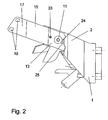
- the bearing axis 5 is via bearing elements 11 and 12 (see FIG. 3 ) are mounted on the two legs 2 and 3, which are arranged between two deformation struts 13 and 14.
- the deformation struts 13 and 14 bear against the sides of the two legs 2 and 3 facing away from the bearing axis 5 and extend away from the base 4 in the direction of a vehicle cross member 21 (see FIG FIG. 6 ).
- the two deformation struts 13 and 14 each have a slope 15 and 16, wherein the distance between the two slopes 15 and 16 decreases with increasing distance to the two legs 2 and 3.
- the two attachment areas 17 and 18 are substantially parallel to each other.
- a plurality of holes 22 are provided in the base 4, so that the bearing block 1 on a vehicle front wall 23 (see FIG. 6 ) can be attached.
- FIG. 2 shows a side view of the embodiment according to FIG. 1 without pedals 6 and 7, wherein the deformation strut 13 at its end facing the leg 2 has a slot 24, the edges 25 in an opening provided in the bearing element 11 annular groove 30 (see Fig. 4 ) intervene.
- Fig. 3 is a sectional view of the embodiment according to FIG. 1 it can be seen, wherein the clutch pedal 7, the bearing sleeve 8, the brake pedal 6, the coupling rod 9 and the spring 10 have been omitted for the sake of clarity.
- the bearing elements 11 and 12 pass through the legs 2 and 3 and extending into the interior 29 of the tube 5 designed as a bearing axis.
- the bearing elements 11 and 12 are axially slidably mounted both in the two legs 2 and 3 and in the interior 29 of the bearing axis 5 in the direction of the longitudinal axis L and secured to the two deformation struts 13 and 14.
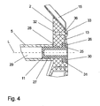
- FIG. 4 is an enlarged view of the in FIG. 3 X marked area.
- the bearing element 11 has a portion 27 of constant diameter, which hineinerstreckt by a provided in the leg 2 bearing hole 28 through into the interior 29 of the bearing shaft 5.
- the bearing element 11 is slidably mounted with the portion 27 in the longitudinal direction L in the bearing hole 28 and in the interior 29 and fixed in the axial direction only by the deformation strut 13, with the edges 25 of the slot 24 in the head portion 26 of the bearing element eleventh trained annular groove 30 engages.
- the head portion 26 has a larger diameter than the portion 27 and is seated in a provided in the leg 2 recess 31st
- the leg 2 has a bore 13 which is open towards the deformation strut 13 and into which is screwed a screw 33 passing through a hole 36 provided in the deformation strut 13, the head of which has a larger diameter than the hole 36.
- the screw 33 which merely serves to fix the deformation strut 13, is so weak that it can be sheared off or pulled out of the leg 2 in the event of an impact accident, without opposing the pushing apart of the two deformation struts 13 and 14 to a significant resistance.
- FIG. 5 is a partial perspective view of the deformation strut 13 with partially illustrated bearing axis 5 can be seen, the bearing block 1 has been omitted.
- the deformation strut 13 has at its end facing the bearing block 1 two lugs 39 which engage in formed in the bearing block 1 clearances (not shown) and serve as a fixation aid.
- the deformation strut 14 is also provided at its end facing the bearing block 1 with two lugs which engage in clearances of the bearing block 1.
- FIG. 6 is a schematic partial view of a motor vehicle 34 can be seen, wherein the pedal assembly according to Fig. 1 is shown in the installed state. In this case, for the sake of clarity of the pedal assembly, only the pedal bracket 1 with the two legs 2 and 3, the base 4 and the two deformation struts 13 and 14 is shown. How out FIG. 6 can be seen, the bearing block 1 through the holes 22 by cross-bolts 35 fixed to the vehicle front wall 23, whereas the two deformation struts 13 and 14 are fastened with their mounting portions 17 and 18 on the vehicle cross member 21.
- FIG. 7 is a partial sectional view of a pedal assembly according to the invention according to a second embodiment can be seen, wherein identical or similar features are denoted by the same reference numerals as in the first embodiment.
- a projection 37 is provided, which engages in the opening provided in the deformation strut 13 hole 36.
- This projection 37 takes over the fixing function of the deformation strut 13 on the leg 2, so that the bore 32 and the screw 33, which are provided according to the first embodiment, can be omitted.
- the fixation of the deformation strut 14 is formed on the leg 3 in a corresponding manner. Except for these two fixations and possibly the lugs, the two embodiments are identical, however.
Landscapes
- Life Sciences & Earth Sciences (AREA)
- Environmental Sciences (AREA)
- Mechanical Control Devices (AREA)
- Braking Elements And Transmission Devices (AREA)
- Sliding-Contact Bearings (AREA)
- Auxiliary Drives, Propulsion Controls, And Safety Devices (AREA)
- Arrangement And Mounting Of Devices That Control Transmission Of Motive Force (AREA)
Claims (19)
- Ensemble de pédale pour véhicule à moteur, comprenant un support de palier (1) qui présente deux branches (2, 3), un axe de palier (5) qui s'étend entre les deux branches (2, 3), au moins une pédale (6, 7) montée sur l'axe de palier (5), deux éléments de palier (11, 12) agencés sur les branches (2, 3) et qui sont en prise avec les deux extrémités de l'axe de palier (5), deux montants de déformation (13, 14), qui s'éloignent du support de palier (1) par les deux éléments de palier (11, 12), caractérisé en ce que les deux branches (2, 3) présentent respectivement un trou de palier (28) et s'étendent dans l'espace compris entre les deux montants de déformation (13, 14), auxquels sont fixés les éléments de palier (11, 12) qui traversent les trous de palier (28) de manière à pouvoir glisser.
- Ensemble de pédale selon la revendication 1, caractérisé en ce que les deux montants de déformation (13, 14) ne sont pas formés d'un seul tenant avec les deux branches (2, 3).
- Ensemble de pédale selon la revendication 1 ou 2, caractérisé en ce que les deux montants de déformation (13, 14) s'étendent l'un vers l'autre dans une zone (15, 16).
- Ensemble de pédale selon l'une quelconque des revendications précédentes, caractérisé en ce que les deux montants de déformation (13, 14) sont agencés en symétrie l'un par rapport à l'autre.
- Ensemble de pédale selon l'une quelconque des revendications précédentes, caractérisé en ce que les deux montants de déformation (13, 14) sont constitués de tôle.
- Ensemble de pédale selon l'une quelconque des revendications précédentes, caractérisé en ce que le support de palier (1) présente un socle (4) par lequel les deux branches (2,3) sont raccordées l'une à l'autre.
- Ensemble de pédale selon l'une quelconque des revendications précédentes, caractérisé en ce que le support de palier (1) est constitué d'un matériau synthétique.
- Ensemble de pédale selon l'une quelconque des revendications précédentes, caractérisé en ce que le diamètre des trous de palier (28) est inférieur au diamètre externe de l'axe de palier (5).
- Ensemble de pédale selon l'une quelconque des revendications précédentes, caractérisé en ce que l'axe de palier (5) présente à ses deux extrémités, respectivement, un évidement (29) dans lequel les éléments de palier (11, 12) s'engagent.
- Ensemble de pédale selon l'une quelconque des revendications précédentes, caractérisé en ce que l'axe de palier (5) se présente sous forme de tube.
- Ensemble de pédale selon l'une quelconque des revendications précédentes, caractérisé en ce que les éléments de palier (11, 12) s'étendent hors des trous de palier (28) sur les côtés des deux branches (2, 3) opposés à l'axe de palier (5).
- Ensemble de pédale selon l'une quelconque des revendications précédentes, caractérisé en ce que les montants de déformation (13, 14) s'engagent dans les éléments de palier (11, 12).
- Ensemble de pédale selon l'une quelconque des revendications précédentes, caractérisé en ce que les extrémités des éléments de palier (11, 12) opposées à l'axe de palier (5) présentent respectivement une rainure annulaire (30), dans laquelle le montant de déformation respectif (13, 14) s'engage.
- Ensemble de pédale selon la revendication 13, caractérisé en ce que les montants de déformation (13, 14) présentent à leurs extrémités tournées vers les deux branches (2, 3) respectivement une fente (24), dont les bords (25) s'engagent dans la rainure annulaire respective (30).
- Ensemble de pédale selon l'une quelconque des revendications précédentes, caractérisé en ce que les deux montants de déformation (13, 14) sont respectivement fixés sur les branches (2, 3) à l'aide d'une vis (33).
- Ensemble de pédale selon l'une quelconque des revendications précédentes, caractérisé en ce que les deux branches (2, 3) présentent sur leurs côtés opposés l'un à l'autre respectivement une saillie (37), qui s'engage dans un trou (36) ménagé dans le montant de déformation respectif (13, 14).
- Ensemble de pédale selon l'une quelconque des revendications précédentes, caractérisé en ce que les deux montants de déformation (13, 14) présentent à leurs extrémités tournées vers le support de palier (1) respectivement au moins un taquet (39) qui s'engage dans le support de palier (1).
- Véhicule automobile pourvu d'un ensemble de pédale selon l'une quelconque des revendications précédentes, une première pièce de véhicule (21) et une seconde pièce de véhicule (23), qui est déplacée dans le cas d'un impact du véhicule (34) dans la direction de la première pièce de véhicule (21), dans lequel les deux montants de déformation (13,14) sont fixés à la première pièce de véhicule (21) et le support de palier (1) est fixé à la deuxième pièce de véhicule (23).
- Véhicule automobile selon la revendication 18, caractérisé en ce que la première pièce de véhicule (21) est une traverse du véhicule et la deuxième pièce de véhicule (23) est formée d'une paroi frontale du véhicule.
Applications Claiming Priority (2)
| Application Number | Priority Date | Filing Date | Title |
|---|---|---|---|
| DE102004028555A DE102004028555A1 (de) | 2004-06-15 | 2004-06-15 | Pedalanordnung für ein Kraftfahrzeug |
| PCT/DE2005/001061 WO2005123467A1 (fr) | 2004-06-15 | 2005-06-15 | Ensemble pedale pour vehicule a moteur |
Publications (2)
| Publication Number | Publication Date |
|---|---|
| EP1755929A1 EP1755929A1 (fr) | 2007-02-28 |
| EP1755929B1 true EP1755929B1 (fr) | 2009-05-13 |
Family
ID=35058944
Family Applications (1)
| Application Number | Title | Priority Date | Filing Date |
|---|---|---|---|
| EP05759921A Not-in-force EP1755929B1 (fr) | 2004-06-15 | 2005-06-15 | Ensemble pedale pour vehicule a moteur |
Country Status (7)
| Country | Link |
|---|---|
| US (1) | US20080006117A1 (fr) |
| EP (1) | EP1755929B1 (fr) |
| JP (1) | JP2008502959A (fr) |
| AT (1) | ATE431273T1 (fr) |
| BR (1) | BRPI0512094A (fr) |
| DE (2) | DE102004028555A1 (fr) |
| WO (1) | WO2005123467A1 (fr) |
Families Citing this family (5)
| Publication number | Priority date | Publication date | Assignee | Title |
|---|---|---|---|---|
| DE102007063884B3 (de) * | 2006-12-08 | 2017-02-09 | Audi Ag | Pedalwerk für ein Kraftfahrzeug sowie Lagerachse für ein solches Pedalwerk |
| DE102007031009B4 (de) * | 2006-12-08 | 2016-03-31 | Audi Ag | Verfahren zur Herstellung eines Pedalwerks für ein Fahrzeug |
| WO2008083339A2 (fr) * | 2006-12-28 | 2008-07-10 | Trapeze Networks, Inc. | Système de réseau sans fil compatible à l'application et procédé |
| DE102008062868A1 (de) * | 2008-12-23 | 2010-07-01 | Volkswagen Ag | Fußhebelwerk an einem Kraftfahrzeug |
| DE102012006614B4 (de) * | 2012-03-30 | 2022-04-21 | Volkswagen Aktiengesellschaft | Lagerbock für ein Fußhebelwerk, Fahrzeug mit einem derartigen Lagerbock und Verfahren zur Herstellung des Lagerbocks |
Family Cites Families (5)
| Publication number | Priority date | Publication date | Assignee | Title |
|---|---|---|---|---|
| DE4344386A1 (de) * | 1993-12-24 | 1995-06-29 | Opel Adam Ag | Pedalwerk für ein Fahrzeug |
| DE19631868B4 (de) * | 1996-08-07 | 2008-09-04 | Adam Opel Ag | Anordnung zur Lagerung eines Pedals |
| DE10040270C2 (de) * | 2000-08-17 | 2002-09-26 | Edscha Ag | Sicherheitseinrichtung im Pedalbereich für einen PKW |
| DE10105266B4 (de) * | 2001-02-02 | 2004-03-25 | ZF Lemförder Metallwaren AG | Haltevorrichtung für die Pedalerie eines Kraftfahrzeuges |
| JP3536103B2 (ja) * | 2001-06-15 | 2004-06-07 | 富士重工業株式会社 | 車両のペダル支持構造 |
-
2004
- 2004-06-15 DE DE102004028555A patent/DE102004028555A1/de not_active Ceased
-
2005
- 2005-06-15 DE DE502005007282T patent/DE502005007282D1/de active Active
- 2005-06-15 JP JP2007515771A patent/JP2008502959A/ja not_active Withdrawn
- 2005-06-15 AT AT05759921T patent/ATE431273T1/de not_active IP Right Cessation
- 2005-06-15 BR BRPI0512094-2A patent/BRPI0512094A/pt not_active IP Right Cessation
- 2005-06-15 US US11/570,631 patent/US20080006117A1/en not_active Abandoned
- 2005-06-15 EP EP05759921A patent/EP1755929B1/fr not_active Not-in-force
- 2005-06-15 WO PCT/DE2005/001061 patent/WO2005123467A1/fr active Application Filing
Also Published As
| Publication number | Publication date |
|---|---|
| ATE431273T1 (de) | 2009-05-15 |
| JP2008502959A (ja) | 2008-01-31 |
| WO2005123467A1 (fr) | 2005-12-29 |
| BRPI0512094A (pt) | 2008-02-06 |
| EP1755929A1 (fr) | 2007-02-28 |
| DE502005007282D1 (de) | 2009-06-25 |
| US20080006117A1 (en) | 2008-01-10 |
| DE102004028555A1 (de) | 2006-02-16 |
Similar Documents
| Publication | Publication Date | Title |
|---|---|---|
| DE10064770A1 (de) | Vorrichtung zur Lagerung eines Pedalhebels eines Kraftfahrzeuges | |
| EP1755929B1 (fr) | Ensemble pedale pour vehicule a moteur | |
| DE102020000356A1 (de) | Fenstereinheit für ein Flugzeug, Flugzeug mit der Fenstereinheit sowie Verfahren zur Montage der Fenstereinheit | |
| DE10040043C1 (de) | Baueinheit für ein Kraftfahrzeug | |
| EP1541424B1 (fr) | Un élément d'absorption de choc en form profilé creux | |
| DE102017211339B4 (de) | Bremskraftverstärkereinrichtung mit einem verformbaren Aktuator | |
| DE102016010356B4 (de) | Kraftfahrzeug und Befestigungvorrichtung für ein Kraftfahrzeug | |
| DE102008026334A1 (de) | Querträger einer Rahmenstruktur | |
| WO2019020268A1 (fr) | Dispositif de protection des piétons pour un véhicule | |
| DE19933734B4 (de) | Strukturbauteil für eine Fahrzeugkarosserie | |
| WO2015078957A1 (fr) | Revêtement de sac gonflable et procédé pour sa fabrication | |
| DE102017008335A1 (de) | Stoßfängereinrichtung für einen Kraftwagen | |
| DE102021111336A1 (de) | Zugglied für eine Kraftfahrzeugkarosserie zur Reduzierung einer Intrusionstiefe | |
| DE102014106719B4 (de) | Aufbau eines Lenkstützglieds | |
| DE202012103704U1 (de) | Verbindungsanordnung zum Verbinden eines Trägerteils mit einem Verkleidungsteil | |
| DE102009026727A1 (de) | Befestigung von Zierleisten | |
| DE29711160U1 (de) | Geteilte Kraftfahrzeug-Fondlehne | |
| DE102006022503A1 (de) | Deformationselement, insbesondere für Kraftfahrzeuge | |
| DE102017211337B4 (de) | Bremskraftverstärkereinrichtung mit einer mehrteiligen Befestigungsvorrichtung für den Bremskraftverstärker | |
| EP1712415B1 (fr) | Véhicule comportant une position normale dans quel un dispositif de fixation pour un phare exige une force nulle et une position crash dans quel le dispositif de fixation exige une force du support, et phare pour ce type de véhicule | |
| DE10058998C1 (de) | Stoßfängereinheit eines Kraftfahrzeuges | |
| DE202017104332U1 (de) | Bremskraftverstärkereinrichtung mit einer mehrteiligen Befestigungsvorrichtung für den Bremskraftverstärker | |
| DE102016200741B4 (de) | Montageeinheit mit Antriebswelle und Antriebswellenhalter sowie Kraftfahrzeug mit Montageeinheit | |
| DE102011100573A1 (de) | Halteelement für eine Abschleppöse eines Kraftwagens sowie Energieabsorptionselement für einen Kraftwagen mit einem solchen Halteelement | |
| DE202005016777U1 (de) | Befestigungsanordnung und Kraftfahrzeug |
Legal Events
| Date | Code | Title | Description |
|---|---|---|---|
| PUAI | Public reference made under article 153(3) epc to a published international application that has entered the european phase |
Free format text: ORIGINAL CODE: 0009012 |
|
| 17P | Request for examination filed |
Effective date: 20061122 |
|
| AK | Designated contracting states |
Kind code of ref document: A1 Designated state(s): AT BE BG CH CY CZ DE DK EE ES FI FR GB GR HU IE IS IT LI LT LU MC NL PL PT RO SE SI SK TR |
|
| RIN1 | Information on inventor provided before grant (corrected) |
Inventor name: MEYER, WOLFGANG Inventor name: HUELSMANN, SILKE Inventor name: BURGSTALER, ANDREE Inventor name: DUETZ, JAN |
|
| DAX | Request for extension of the european patent (deleted) | ||
| GRAP | Despatch of communication of intention to grant a patent |
Free format text: ORIGINAL CODE: EPIDOSNIGR1 |
|
| GRAJ | Information related to disapproval of communication of intention to grant by the applicant or resumption of examination proceedings by the epo deleted |
Free format text: ORIGINAL CODE: EPIDOSDIGR1 |
|
| GRAP | Despatch of communication of intention to grant a patent |
Free format text: ORIGINAL CODE: EPIDOSNIGR1 |
|
| GRAS | Grant fee paid |
Free format text: ORIGINAL CODE: EPIDOSNIGR3 |
|
| GRAA | (expected) grant |
Free format text: ORIGINAL CODE: 0009210 |
|
| AK | Designated contracting states |
Kind code of ref document: B1 Designated state(s): AT BE BG CH CY CZ DE DK EE ES FI FR GB GR HU IE IS IT LI LT LU MC NL PL PT RO SE SI SK TR |
|
| REG | Reference to a national code |
Ref country code: GB Ref legal event code: FG4D Free format text: NOT ENGLISH |
|
| REG | Reference to a national code |
Ref country code: CH Ref legal event code: EP |
|
| REG | Reference to a national code |
Ref country code: IE Ref legal event code: FG4D |
|
| REF | Corresponds to: |
Ref document number: 502005007282 Country of ref document: DE Date of ref document: 20090625 Kind code of ref document: P |
|
| PG25 | Lapsed in a contracting state [announced via postgrant information from national office to epo] |
Ref country code: LT Free format text: LAPSE BECAUSE OF FAILURE TO SUBMIT A TRANSLATION OF THE DESCRIPTION OR TO PAY THE FEE WITHIN THE PRESCRIBED TIME-LIMIT Effective date: 20090513 Ref country code: PT Free format text: LAPSE BECAUSE OF FAILURE TO SUBMIT A TRANSLATION OF THE DESCRIPTION OR TO PAY THE FEE WITHIN THE PRESCRIBED TIME-LIMIT Effective date: 20090913 Ref country code: FI Free format text: LAPSE BECAUSE OF FAILURE TO SUBMIT A TRANSLATION OF THE DESCRIPTION OR TO PAY THE FEE WITHIN THE PRESCRIBED TIME-LIMIT Effective date: 20090513 Ref country code: ES Free format text: LAPSE BECAUSE OF FAILURE TO SUBMIT A TRANSLATION OF THE DESCRIPTION OR TO PAY THE FEE WITHIN THE PRESCRIBED TIME-LIMIT Effective date: 20090824 |
|
| NLV1 | Nl: lapsed or annulled due to failure to fulfill the requirements of art. 29p and 29m of the patents act | ||
| PG25 | Lapsed in a contracting state [announced via postgrant information from national office to epo] |
Ref country code: SI Free format text: LAPSE BECAUSE OF FAILURE TO SUBMIT A TRANSLATION OF THE DESCRIPTION OR TO PAY THE FEE WITHIN THE PRESCRIBED TIME-LIMIT Effective date: 20090513 Ref country code: SE Free format text: LAPSE BECAUSE OF FAILURE TO SUBMIT A TRANSLATION OF THE DESCRIPTION OR TO PAY THE FEE WITHIN THE PRESCRIBED TIME-LIMIT Effective date: 20090813 Ref country code: NL Free format text: LAPSE BECAUSE OF FAILURE TO SUBMIT A TRANSLATION OF THE DESCRIPTION OR TO PAY THE FEE WITHIN THE PRESCRIBED TIME-LIMIT Effective date: 20090513 Ref country code: PL Free format text: LAPSE BECAUSE OF FAILURE TO SUBMIT A TRANSLATION OF THE DESCRIPTION OR TO PAY THE FEE WITHIN THE PRESCRIBED TIME-LIMIT Effective date: 20090513 Ref country code: IS Free format text: LAPSE BECAUSE OF FAILURE TO SUBMIT A TRANSLATION OF THE DESCRIPTION OR TO PAY THE FEE WITHIN THE PRESCRIBED TIME-LIMIT Effective date: 20090913 |
|
| REG | Reference to a national code |
Ref country code: IE Ref legal event code: FD4D |
|
| BERE | Be: lapsed |
Owner name: ZF FRIEDRICHSHAFEN A.G. Effective date: 20090630 |
|
| PG25 | Lapsed in a contracting state [announced via postgrant information from national office to epo] |
Ref country code: RO Free format text: LAPSE BECAUSE OF FAILURE TO SUBMIT A TRANSLATION OF THE DESCRIPTION OR TO PAY THE FEE WITHIN THE PRESCRIBED TIME-LIMIT Effective date: 20090513 Ref country code: MC Free format text: LAPSE BECAUSE OF NON-PAYMENT OF DUE FEES Effective date: 20090630 Ref country code: CZ Free format text: LAPSE BECAUSE OF FAILURE TO SUBMIT A TRANSLATION OF THE DESCRIPTION OR TO PAY THE FEE WITHIN THE PRESCRIBED TIME-LIMIT Effective date: 20090513 Ref country code: DK Free format text: LAPSE BECAUSE OF FAILURE TO SUBMIT A TRANSLATION OF THE DESCRIPTION OR TO PAY THE FEE WITHIN THE PRESCRIBED TIME-LIMIT Effective date: 20090513 Ref country code: IE Free format text: LAPSE BECAUSE OF FAILURE TO SUBMIT A TRANSLATION OF THE DESCRIPTION OR TO PAY THE FEE WITHIN THE PRESCRIBED TIME-LIMIT Effective date: 20090513 Ref country code: EE Free format text: LAPSE BECAUSE OF FAILURE TO SUBMIT A TRANSLATION OF THE DESCRIPTION OR TO PAY THE FEE WITHIN THE PRESCRIBED TIME-LIMIT Effective date: 20090513 |
|
| REG | Reference to a national code |
Ref country code: CH Ref legal event code: PL |
|
| PG25 | Lapsed in a contracting state [announced via postgrant information from national office to epo] |
Ref country code: SK Free format text: LAPSE BECAUSE OF FAILURE TO SUBMIT A TRANSLATION OF THE DESCRIPTION OR TO PAY THE FEE WITHIN THE PRESCRIBED TIME-LIMIT Effective date: 20090513 |
|
| PLBE | No opposition filed within time limit |
Free format text: ORIGINAL CODE: 0009261 |
|
| STAA | Information on the status of an ep patent application or granted ep patent |
Free format text: STATUS: NO OPPOSITION FILED WITHIN TIME LIMIT |
|
| REG | Reference to a national code |
Ref country code: FR Ref legal event code: ST Effective date: 20100226 |
|
| PG25 | Lapsed in a contracting state [announced via postgrant information from national office to epo] |
Ref country code: BG Free format text: LAPSE BECAUSE OF FAILURE TO SUBMIT A TRANSLATION OF THE DESCRIPTION OR TO PAY THE FEE WITHIN THE PRESCRIBED TIME-LIMIT Effective date: 20090813 |
|
| 26N | No opposition filed |
Effective date: 20100216 |
|
| GBPC | Gb: european patent ceased through non-payment of renewal fee |
Effective date: 20090813 |
|
| PG25 | Lapsed in a contracting state [announced via postgrant information from national office to epo] |
Ref country code: FR Free format text: LAPSE BECAUSE OF NON-PAYMENT OF DUE FEES Effective date: 20090715 Ref country code: LI Free format text: LAPSE BECAUSE OF NON-PAYMENT OF DUE FEES Effective date: 20090630 Ref country code: CH Free format text: LAPSE BECAUSE OF NON-PAYMENT OF DUE FEES Effective date: 20090630 |
|
| PG25 | Lapsed in a contracting state [announced via postgrant information from national office to epo] |
Ref country code: BE Free format text: LAPSE BECAUSE OF NON-PAYMENT OF DUE FEES Effective date: 20090630 |
|
| PG25 | Lapsed in a contracting state [announced via postgrant information from national office to epo] |
Ref country code: AT Free format text: LAPSE BECAUSE OF NON-PAYMENT OF DUE FEES Effective date: 20090615 |
|
| PG25 | Lapsed in a contracting state [announced via postgrant information from national office to epo] |
Ref country code: GR Free format text: LAPSE BECAUSE OF FAILURE TO SUBMIT A TRANSLATION OF THE DESCRIPTION OR TO PAY THE FEE WITHIN THE PRESCRIBED TIME-LIMIT Effective date: 20090814 |
|
| PG25 | Lapsed in a contracting state [announced via postgrant information from national office to epo] |
Ref country code: GB Free format text: LAPSE BECAUSE OF NON-PAYMENT OF DUE FEES Effective date: 20090813 |
|
| PG25 | Lapsed in a contracting state [announced via postgrant information from national office to epo] |
Ref country code: IT Free format text: LAPSE BECAUSE OF FAILURE TO SUBMIT A TRANSLATION OF THE DESCRIPTION OR TO PAY THE FEE WITHIN THE PRESCRIBED TIME-LIMIT Effective date: 20090513 |
|
| PG25 | Lapsed in a contracting state [announced via postgrant information from national office to epo] |
Ref country code: LU Free format text: LAPSE BECAUSE OF NON-PAYMENT OF DUE FEES Effective date: 20090615 |
|
| PG25 | Lapsed in a contracting state [announced via postgrant information from national office to epo] |
Ref country code: HU Free format text: LAPSE BECAUSE OF FAILURE TO SUBMIT A TRANSLATION OF THE DESCRIPTION OR TO PAY THE FEE WITHIN THE PRESCRIBED TIME-LIMIT Effective date: 20091114 |
|
| PG25 | Lapsed in a contracting state [announced via postgrant information from national office to epo] |
Ref country code: TR Free format text: LAPSE BECAUSE OF FAILURE TO SUBMIT A TRANSLATION OF THE DESCRIPTION OR TO PAY THE FEE WITHIN THE PRESCRIBED TIME-LIMIT Effective date: 20090513 |
|
| PG25 | Lapsed in a contracting state [announced via postgrant information from national office to epo] |
Ref country code: CY Free format text: LAPSE BECAUSE OF FAILURE TO SUBMIT A TRANSLATION OF THE DESCRIPTION OR TO PAY THE FEE WITHIN THE PRESCRIBED TIME-LIMIT Effective date: 20090513 |
|
| REG | Reference to a national code |
Ref country code: DE Ref legal event code: R081 Ref document number: 502005007282 Country of ref document: DE Owner name: BOGE ELASTMETALL GMBH, DE Free format text: FORMER OWNER: ZF FRIEDRICHSHAFEN AG, 88046 FRIEDRICHSHAFEN, DE Effective date: 20141119 |
|
| PGFP | Annual fee paid to national office [announced via postgrant information from national office to epo] |
Ref country code: DE Payment date: 20160518 Year of fee payment: 12 |
|
| REG | Reference to a national code |
Ref country code: DE Ref legal event code: R119 Ref document number: 502005007282 Country of ref document: DE |
|
| PG25 | Lapsed in a contracting state [announced via postgrant information from national office to epo] |
Ref country code: DE Free format text: LAPSE BECAUSE OF NON-PAYMENT OF DUE FEES Effective date: 20180103 |