EP1755277A1 - Radio frequency assigning apparatus, wireless communication system, and radio frequency assigning method - Google Patents
Radio frequency assigning apparatus, wireless communication system, and radio frequency assigning method Download PDFInfo
- Publication number
- EP1755277A1 EP1755277A1 EP05748900A EP05748900A EP1755277A1 EP 1755277 A1 EP1755277 A1 EP 1755277A1 EP 05748900 A EP05748900 A EP 05748900A EP 05748900 A EP05748900 A EP 05748900A EP 1755277 A1 EP1755277 A1 EP 1755277A1
- Authority
- EP
- European Patent Office
- Prior art keywords
- node
- radio
- radio channel
- communication link
- nodes
- Prior art date
- Legal status (The legal status is an assumption and is not a legal conclusion. Google has not performed a legal analysis and makes no representation as to the accuracy of the status listed.)
- Granted
Links
Images


Classifications
-
- H—ELECTRICITY
- H04—ELECTRIC COMMUNICATION TECHNIQUE
- H04W—WIRELESS COMMUNICATION NETWORKS
- H04W72/00—Local resource management
- H04W72/20—Control channels or signalling for resource management
Definitions
- the present invention generally relates to a radio channel allocation apparatus, a radio communication system, and a radio channel allocation method, in which allocation of radio channels is controlled in a radio communication system which performs an autonomous distributed type asynchronous digital radio transmission using a virtual carrier sense.
- radio signals In an asynchronous digital radio transmission system in which autonomous distributed control is assumed, radio signals must be transmitted or received between radio stations where the radio signals can reach each station so as to control allocation of radio channels (radio frequencies).
- the virtual carrier sense has not been publicly known at the time of applying for a patent of the present invention as far as the applicant of the present invention knows.
- FIG. 1 is a diagram showing a collision of transmission request signals in a multi-hop transmission.
- a case is studied.
- a radio station 13 and a radio station 14 establish communications by exchanging a transmission request signal and a preparation completion signal
- a radio station 12 has transmission inhibition conditions.
- the transmission request signals from the radio station 13 to the radio stations 12 and 14 collide.
- FIG. 2 is a diagram showing transmission inhibition conditions in the multi-hop transmission.
- the radio station 11 discards data to be transmitted due to impossibility of communications. Consequently, the transmission throughput may be greatly degraded caused by discarding the data.
- an exposed terminal problem may be generated due to a positional relationship among radio stations which desire to perform communications.
- FIG. 3A is a diagram showing an exposed terminal problem.
- FIG. 3A a case is described in which communications between radio stations 11 and 12 and between radio stations 13 and 14 are performed using the same radio frequency (channel) f 1 .
- a signal from a radio station reaches only a nearest radio station, for example, during communications between the radio stations 13 and 14, communication quality between the radio stations 11 and 12 is greatly degraded.
- FIG. 3B is a diagram showing a solution to the exposed terminal problem.
- a radio frequency f 2 is used for communications between the radio stations 11 and 12, while the radio frequency f 1 is used for communications between the radio stations 13 and 14.
- a radio channel allocation apparatus in which transmission throughput degradation in a multi-hop transmission can be prevented.
- a radio channel allocation apparatus in which increase of the number of radio channels (frequencies) can be restrained while solving an exposed terminal problem.
- a radio channel allocation apparatus of a node in a radio communication system which controls to allocate a radio channel between nodes by a virtual carrier sense.
- the radio channel allocation apparatus includes a node information collecting unit which collects information of a neighboring node to which the node can directly transmit data, and a radio channel determining unit that determines a radio channel.
- the determined radio channel is allocated to a communication link between a node which has transmission inhibition conditions and another node which does not have the transmission inhibition conditions by communications between predetermined nodes.
- the determined radio channel is a different radio channel from a radio channel between the predetermined nodes, based on node information of the node and the neighboring node. Therefore, transmission throughput degradation can be prevented.
- a radio communication system which controls to allocate a radio channel between nodes by a virtual carrier sense.
- the radio communication system includes a node information collecting unit which collects information of a neighboring node to which a node can directly transmit data, and a radio channel determining unit that determines a radio channel.
- the determined radio channel is allocated to a communication link between a node which has transmission inhibition conditions and another node which does not have the transmission inhibition conditions by communications between predetermined nodes.
- the determined radio channel is a different radio channel from a radio channel between the predetermined nodes, based on node information of the node and the neighboring node. Therefore, a multi-hop transmission can be performed by preventing transmission throughput degradation.
- a radio channel allocation method in a radio communication system which controls to allocate a radio channel between nodes by a virtual carrier sense.
- the radio channel allocation method includes the steps of collecting information of a neighboring node to which a node can directly transmit data; receiving information of the neighboring node collected at the node at the neighboring node; and determining a radio channel, which is allocated to a communication link between a node which has transmission inhibition conditions and another node which does not have the transmission inhibition conditions by communications between predetermined nodes.
- the determined radio channel is a different radio channel from a radio channel between the predetermined nodes, based on the received node information.
- the method further includes the step of transmitting information of the determined radio channel. Therefore, the radio channels can be allocated while preventing transmission throughput degradation.
- a radio channel allocation apparatus, a radio communication system, and a radio channel allocation method can prevent transmission throughput degradation in a multi-hop transmission.
- the transmission throughput degradation in the multi-hop transmission shown in FIGs. 1 and 2 is generated in the following situation.
- the radio station 11 intends to transmit data to the radio station 12 which can recognize a transmission situation between the radio stations 13 and 14 by using the same radio channel as that being used between the radio stations 13 and 14, while the radio station 11 cannot recognize the transmission situation between the radio stations 13 and 14.
- radio channels are determined to solve the above problem, in a three-hop transmission, it is determined that a radio channel of a 1 st hop is different from that of a 3 rd .
- an allocation method of radio channels (frequencies) is not fixed.
- the neighboring node information can be formed by the following method. For example, a packet called "Hello Packet" which is a packet exclusively for forming the neighboring node information is broadcast, and a packet responding to the "Hello Packet" is received. As another method, the neighboring node information can be formed by, for example, receiving data transmissions which are performed between other radio stations.
- FIG. 4 is a diagram showing the radio communication system according to the first embodiment of the present invention.
- FIG. 5 is a diagram showing a radio station shown in FIG. 4.
- the radio communication system includes radio stations 110, 120, 130, and 140.
- the number of the radio stations in the radio communication system is not limited to four, and five or more radio stations can be included in the radio communication system.
- the radio station 110 includes a radio channel allocation apparatus.
- the radio channel allocation apparatus includes a transmitting/receiving section 111, a controller 112, a radio channel setting section 113, a neighboring node information collecting section 114, and a neighboring node information forming section 115.
- the transmitting/receiving section 111, the radio channel setting section 113, the neighboring node information collecting section 114, and the neighboring node information forming section 115 are connected to the controller 112.
- the controller 112 controls all the sections in the radio channel allocation apparatus.
- the radio stations 120, 130, and 140 have the same structure as that of the radio station 110; therefore, the same description is omitted.
- the neighboring node information collecting section 114 collects information of neighboring nodes (radio stations) to which the radio station 110 can directly transmit data.
- the neighboring node information collecting section 114 in the radio station 110 collects information of the radio stations 110 and 120.
- the information of the neighboring nodes includes information of its own radio station.
- the neighboring node information forming section 115 forms neighboring node information by using the information collected by the neighboring node information collecting section 114.
- the neighboring node information forming section 115 forms the neighboring node information in which information of the radio stations 110 and 120 is included.
- the transmitting/receiving section 111 transmits the neighboring node information formed by the neighboring node information forming section 115 to the radio station 120.
- the neighboring node information collecting section 114 collects information of neighboring nodes of the radio station 120.
- the neighboring node information collecting section 114 collects information of the radio stations 120, 110, and 130.
- the neighboring node information forming section 115 of the radio station 120 forms neighboring node information by adding the neighboring node information received from the radio station 110 to the neighboring node information formed by the own radio station 120.
- the neighboring node information forming section 115 forms the neighboring node information including the information of the radio stations 110 and 120 which are connectable from the radio station 110, and the information of the radio stations 120, 110, and 130 which 110 and 130 are connectable from the radio station 120.
- the transmitting/receiving section 111 of the radio station 120 transmits the neighboring node information formed by the neighboring node information forming section 115 to the radio station 130.
- the neighboring node information collecting section 114 collects information of neighboring nodes of the radio station 130.
- the neighboring node information collecting section 114 collects information of the radio stations 130, 120, and 140.
- the neighboring node information forming section 115 of the radio station 130 forms neighboring node information by adding the neighboring node information received from the radio station 120 to the neighboring node information formed by the own radio station 130.
- the neighboring node information forming section 115 forms neighboring node information including the information of the radio stations 110 and 120 of which 120 is connectable from the radio station 110, the information of the radio stations 120, 110, and 130 of which 110 and 130 are connectable from the radio station 120, and the information of the radio stations 130, 120, and 140 of which 120 and 140 are connectable form the radio station 130.
- the transmitting/receiving section 111 of the radio station 130 transmits the neighboring node information formed by the neighboring node information forming section 115 to the radio station 140.
- FIG. 6 is a diagram showing the radio communication system in which radio channels are determined according to the first embodiment of the present invention.
- the radio channel setting section 113 determines each radio channel which is used between the radio stations from the received neighboring node information. For example, it is determined that a radio channel 1 is between the radio stations 110 and 120, the radio channel 1 is between the radio stations 120 and 130, and a radio channel 2 is between the radio stations 130 and 140.
- the transmitting/receiving section 111 of the radio station 140 transmits the determined radio channels to the radio station 130 as radio channel setting information.
- the radio channel setting section 113 deletes the radio channel setting information between the radio stations 130 and 140 from the received radio channel setting information.
- the transmitting/receiving section 111 of the radio station 130 transmits the radio channel setting information in which the radio channel setting information between the radio stations 130 and 140 is deleted to the radio station 120. That is, the transmitting/receiving section 111 of the radio station 130 transmits the radio channel setting information to the radio station 120 in which information the radio channel 1 is between the radio stations 110 and 120 and the radio channel 1 is between the radio stations 120 and 130.
- the radio channel setting section 113 deletes the radio channel setting information between the radio stations 120 and 130 from the received radio channel setting information.
- the transmitting/receiving section 111 of the radio station 120 transmits the radio channel setting information in which the radio channel setting information between the radio stations 120 and 130 is deleted to the radio station 110. That is, the transmitting/receiving section 111 of the radio station 120 transmits the radio channel setting information in which the radio channel 1 is between the radio stations 110 and 120 to the radio station 110.
- the radio channel setting section 113 sets the radio channel corresponding to the received radio channel setting information. That is, the radio channel setting section 113 sets that the radio channel between the radio stations 110 and 120 is the radio channel 1.
- the radio channel setting section 113 sets the radio channel corresponding to the received radio channel setting information. That is, the radio channel setting section 113 of the radio station 120 sets that the radio channel between the radio stations 120 and 130 is the radio channel 1 and the radio channel setting section 113 of the radio station 130 sets that the radio channel between the radio stations 130 and 140 is the radio channel 2.
- FIG. 7A is a diagram showing a radio communication system in which a six-hop transmission is performed in seven nodes (radio stations).
- a circled number shows a node and an arrow shows a communication link between the nodes.
- the radio waves are transmitted between the nodes 1 and 4, between the nodes 4 and 7, and between the bodes 1 and 7.
- radio waves from the node 1 reach the nodes 2, 4, and 7.
- a connection (communication link) between the nodes 2 and another node on communication links is defined as a connection A
- one of the connections other than the connection A on the communication links is defined as a connection B.
- the node 2 determines that a connection between the nodes 2 and 1 is the connection A and a connection between the nodes 4 and 5 is the connection B, which connection B is one of the connections other than the connection A.
- the destination station determines that the connection A uses a different radio channel from a radio channel which is used in the connection B.
- radio waves from a transmission station or a reception station in the connection A reach a transmission station in the connection B, and the radio waves neither from the transmission station nor the reception station in the connection A reach a reception station in the connection B.
- the radio waves from the transmission station or the reception station in the connection A reach the reception station in the connection B, and the radio waves neither from the transmission station nor the reception station in the connection A reach the transmission station in the connection B.
- the radio waves from the transmission station or the reception station in the connection B reach the transmission station in the connection A, and the radio waves neither from the transmission station nor the reception station in the connection B reach the reception station in the connection A.
- the radio waves from the transmission station or the reception station in the connection B reach the reception station in the connection A, and the radio waves neither from the transmission station nor the reception station in the connection B reach the transmission station in the connection A.
- the node 2 determines that the connection between the nodes 2 and 1 is the connection A on the communication links and the connection between the nodes 4 and 5 is the connection B on the communication links, which connection B is one of the connections other than the connection A.
- the node 2 determines whether the connections A and B accommodate any one of the following cases.
- radio waves from the node 1 or 2 in the connection A reach the node 4 in the connection B, and the radio waves neither from the node 1 nor the node 2 in the connection A reach the node 5 in the connection B.
- radio waves from the node 1 or 2 reach the node 5 in the connection B.
- radio waves from the node 4 or 5 reach the node 1, and the radio waves neither from the node 4 nor the node 5 reach the node 2.
- radio waves from the node 4 or 5 reach the node 2, and the radio waves neither from the node 4 nor the node 5 reach the node 1.
- the first case is accommodated, that is, the radio waves from the node 1 or the node 2 reach the node 4, and the radio waves neither from the node 1 nor the node 2 reach the node 5. Therefore, it is determined that the radio channel between the nodes 1 and 2 in the connection A is different from the radio channel between the nodes 4 and 5 in the connection B.
- connection between the nodes 2 and 1 is the connection A and a connection, for example, between nodes 6 and 7 is the connection B which is one of the connections other than the connection A
- FIG. 7B is a diagram showing relationships among radio channels between nodes in the radio communication system in which the six-hop transmission is performed in the seven nodes.
- circled numbers are nodes and arrows are connections (communication links) between the nodes, and a radio channel between nodes "n” and “m” is C m,n (each of n and m is a different integer).
- S 1 (k) is "true” when a carrier of the node “k” can be sensed at a node "l”, that is, S 1 (k) is "true” when radio waves of the node "k” can reach the node "l”.
- radio channels which must be different from each other are shown, for example, in the upper part of FIG. 7B, the radio channel C 1,2 is different from the radio channel C 4,5 , and the radio channel C 1,2 is different from the radio channel C 6,7 . This case is described in FIG. 7A.
- a radio channel between the nodes 2 and 3 must be different from a radio channel between the nodes 4 and 5.
- a radio channel between the nodes 6 and 7 must be different from a radio channel between the nodes 1 and 2 and a radio channel between the nodes 3 and 4.
- FIG. 7C is a diagram showing relationships among radio channels between nodes in a radio communication system in which a six-hop transmission is performed in seven nodes.
- a radio channel between nodes "n" and "m” is C m,n (each of n and m is a different integer)
- an arrow shows a relationship between the radio channels, and the relationship signifies that the radio channels must be different from each other.
- a connection between the nodes 5 and 6 must be a different radio channel from a connection between the nodes 1 and 2 and a connection between the nodes 3 and 4.
- the radio channels C 1,2 , C 3,4 , and C 2,3 can use the same radio channel
- the radio channels C 5,6 , C 6,7 , and C 4,5 can use the same radio channel. That is, the number of necessary radio channels is two.
- the first radio channel between the third and fourth radio stations is determined to be a different radio channel from the first radio channel based on the neighboring node information.
- FIG. 8 is a flowchart showing operations of the radio communication system according to the first embodiment of the present invention. Referring to FIG. 8, the operations of the radio communication system according to the first embodiment of the present invention are described.
- the radio station 110 collects information of neighboring nodes of the radio station 110, forms neighboring node information by using the collected information (step S702), and transmits the formed neighboring node information to the radio station 120 (step S704).
- the radio station 120 receives the neighboring node information from the radio station 110, collects information of neighboring nodes of the radio station 120 (step S706), forms neighboring node information by adding the collected information to the neighboring node information received from the radio station 110 (step S708), and transmits the formed neighboring node information to the radio station 130 (step S710).
- the radio station 130 receives the neighboring node information from the radio station 120, collects information of neighboring nodes of the radio station 130 (step S712), forms neighboring node information by adding the collected information to the neighboring node information received from the radio station 120 (step S714), and transmits the formed neighboring node information to the radio station 140 (step S716).
- the radio station 140 receives the neighboring node information from the radio station 130, and determines radio channels between corresponding radio stations based on the received neighboring node information of all the radio stations on communication links by referring to the processes shown in FIGs. 7A through 7C (step S718). Then, the radio station 140 transmits the determined radio channels to the radio station 130 as radio channel setting information (step S720).
- the radio station 130 receives the radio channel setting information from the radio station 140, sets a radio channel between the radio stations 130 and 140 (S722), and deletes the radio channel setting information between the radio stations 130 and 140 from the received radio channel setting information (step S724). Then, the radio station 130 transmits the radio channel setting information in which the radio channel setting information between the radio stations 130 and 140 is deleted to the radio station 120 (step S726).
- the radio station 120 receives the radio channel setting information from the radio station 130, sets a radio channel between the radio stations 120 and 130 (S728), and deletes the radio channel setting information between the radio stations 120 and 130 from the received radio channel setting information (step S730). Then, the radio station 120 transmits the radio channel setting information in which the radio channel setting information between the radio stations 120 and 130 is deleted to the radio station 110 (step S732).
- the radio station 110 receives the radio channel setting information from the radio station 120, and sets a radio channel between the radio stations 110 and 120 based on the received radio channel setting information (step S736).
- a radio station collects the neighboring node information of its own radio station after receiving the neighboring node information from a preceding radio station.
- the radio station can collect the neighboring node information of its own radio station beforehand. In this case, the time needed to set the radio channel can be shortened.
- the radio communication system which performs a three-hop transmission by using four radio stations is described.
- the present embodiment is applied to a radio communication system using five or more radio stations, the transmission throughput degradation in a multi-hop transmission can be prevented.
- FIGs. 9A through 9C are diagrams showing radio channel settings in a radio communication system of a nine-hop transmission according to the first embodiment of the present invention. Referring to FIGs. 9A through 9C, as an example, combinations of different radio channel settings in the nine-hop transmission are described. In each of FIGs. 9A, 9B, and 9C, a different combination of radio channel settings is shown, and a square shows a radio channel in a communication link between nodes. In FIGs. 9A through 9C, a different radio channel (frequency) must be allocated in each of the radio channels connected by a line, and each radio channel has a pattern, where the same radio channel has the same pattern. In FIGs. 9A and 9B, the necessary number of radio channels is two, and in FIG. 9C, the necessary number of radio channels is three, by the patterns. In the above structure, the number of radio channels to be allocated can be small.
- the first embodiment of the present invention is not limited to the above specific embodiment and can be applied to any communication links between nodes (radio stations).
- the above radio channel allocation method is applied to a mesh network, and can be applied to both an autonomous distributed control system and a centralized control system.
- FIG. 10 is a diagram showing radio channel settings according to the second embodiment of the present invention.
- a criterion for whether an exposed terminal problem is generated among the following communication links is described. That is, in predetermined nodes k, 1, m, and n, a communication link Ck,l between the nodes k and 1 and a communication link Cm,n between the nodes m and n exist, and the criterion for whether the exposed terminal problem is generated between the communication link Ck,l and the communication link Cm,n is described.
- the criterion is whether a carrier can be sensed between the nodes k and 1, and whether a carrier can be sensed between the nodes m and n.
- the criterion is TRUE, an exposed terminal problem is generated.
- the relationship between the communication links Ck,l and Cm,n is determined to be a connection relationship in which an exposed terminal problem is generated between the communication links, by using the chromatic graph.
- the relationship between the communication links Ck,l and Cm,n is determined to be a connection relationship in which an exposed terminal problem is not generated between the communication links, by using the chromatic graph.
- the above determination is applied to communications between all the communication links, all connection relationships between the communication links can be expressed on the chromatic graph.
- the present embodiment is not limited to TCP and can be applied to other protocols.
- the present embodiment is not limited to two-way communications and can be applied to one-way communications.
- FIG. 11A is a diagram showing communication links in a mesh network of six nodes.
- FIG. 11B is a diagram showing a chromatic graph obtained from the communication links shown in FIG. 11A.
- communications links exist between nodes 1 and 2, between the node 1 and a node 3, between the nodes 2 and 3, between the node 1 and a node 5, between the node 2 and a node 6, between the node 3 and a node 4, between the nodes 4 and 5, between the nodes 4 and 6, and between the nodes 5 and 6.
- Data transmission can be performed on all the communication links. That is, a carrier sense can be performed on all the communication links.
- the chromatic graph is formed as shown in FIG. 11B, and radio channel allocation to avoid an exposed terminal problem can be performed by utilizing the chromatic graph.
- combinations of the communication links in which an exposed terminal problem may be generated are as follows.
- the number of the communication links is exponentially increased corresponding to an increase of the number of nodes.
- the chromatic graph becomes complex and the number of the radio channels to be required to avoid the exposed terminal problem is larger than that in a multi-hop transmission.
- FIG. 12A is a diagram showing modified communication links shown in FIG. 11A.
- FIG. 12B is a diagram showing a chromatic graph obtained from the modified communication links shown in FIG. 12A.
- FIG. 12A when data transmission using the communication links between the nodes 1 and 5 and between the nodes 2 and 6 shown in FIG. 11A is prohibited (those links are shown by dashed lines in FIG. 12A), since these communication links are deleted from the chromatic graph, the chromatic graph can be simplified as shown in FIG. 12B.
- the dashed lines become carrier sensing lines in FIG. 12A.
- FIG. 13 is a diagram showing the radio station according to the second embodiment of the present invention.
- a radio station 110 has the same reference number as that in the first embodiment; however the structure is different from that in the first embodiment.
- the radio station 110 includes a radio channel allocation apparatus.
- the radio channel allocation apparatus includes a transmitting/receiving section 111, a controller 112, a radio channel setting section 113, a neighboring node information collecting section 114, and a neighboring node information forming section 115.
- the transmitting/receiving section 111, the radio channel setting section 113, the neighboring node information collecting section 114, and the neighboring node information forming section 115 are connected to the controller 112.
- the controller 112 controls all sections in the radio channel allocation apparatus.
- the radio channel setting section 113 includes an analogous link determining section 116, a link grouping section 117, and a frequency setting section 118.
- the structure of the radio channel setting section 113 is different from that in the first embodiment.
- Each of other radio stations in the mesh network has the same structure as that of the radio station 110.
- the neighboring node information forming section 115 broadcasts a packet via the controller 112 and the transmitting/receiving section 111, in which packet information of its own radio station such as an ID of the own radio station, a using frequency in the own radio station, and neighboring node information of the own radio station are included.
- the neighboring node information collecting section 114 collects information of the neighboring nodes.
- the neighboring node information forming section 115 forms neighboring node information by adding neighboring node information of its own radio station to the received neighboring node information and broadcasts a packet in which information of its own radio station and the formed neighboring node information are included.
- the neighboring node information collecting section 114 of each radio station can collect information of neighboring nodes.
- the neighboring node information forming section 115 in each radio station forms a chromatic graph based on the formed neighboring node information and estimates combinations of communication links in which an exposed terminal problem may be generated. Specifically, combinations of communication links in which an exposed terminal problem may be generated are estimated based on the following basis. That is, in a case where both a transmission station and a reception station on a communication link (communication link A) which is recognized by the neighboring node information are out of a communication range with another radio station (radio station B) which is recognized by the neighboring node information, an exposed terminal problem is generated in communications between its own radio station and the radio station B during communications on the communication link A.
- the neighboring node information forming section 115 in each radio station estimates a combination of communication links in which an exposed terminal problem may be generated based on the formed neighboring node information and broadcasts a packet including the estimated result.
- Each radio station recognizes all combinations of communication links, in which the exposed terminal problem may be generated, surrounding its own radio station by referring to the combinations of the communication links in which the exposed terminal problem may be generated included in the broadcast packet.
- the analogous link determining section 116 in each radio station recognizes the combinations of the communication links, in which the exposed terminal problem may be generated, surrounding its own radio station and searches combinations of communication links having a common point (common communication link) with which communication link an exposed terminal problem may be generated, and determines the combinations of the communication links in which the exposed terminal problem may be generated. That is, the analogous link determining section 116 searches for a combination of communication links having a common point in which an exposed terminal problem may be generated from the combinations of the communication links.
- the link grouping section 117 forms a group of communication links, and grouping of the communication links is described below in detail.
- FIG. 14A is a diagram showing communication links in a mesh network in which six radio stations (nodes) are included.
- a circled number shows a node and a continuous line shows a communication link between nodes.
- FIG. 14B is a diagram showing a chromatic graph obtained from the communication links shown in FIG. 14A.
- a rectangle shows a communication link and a continuous line shows a combination of the communication links in which an exposed terminal problem may be generated.
- communications links exist between nodes 1 and 2, between the node 1 and a node 3, between the node 1 and a node 5, between the nodes 2 and 3, between the node 2 and a node 4, between the nodes 3 and 4, between the nodes 3 and 5, between the node 4 and a node 6, and between the nodes 5 and 6.
- Each node forms neighboring node information. Then, each node estimates a combination of communication links in which an exposed terminal problem may be generated based on the above conditions of the combination of the communication links in which the exposed terminal problem may be generated. The conditions are used to allocate different frequencies to corresponding communication links to be connected. Based on the estimation, the chromatic graph shown in FIG. 14B is formed.
- restriction on a frequency allocating to communication links exists in a combination of the communication links C4,6 and C1,2, a combination of the communication links C4,6 and C1,3, a combination of the communication links C4,6 and C2,3, a combination of the communication links C4,6 and C1,5, a combination of the communication links C5,6 and C1,2, a combination of the communication links C5,6 and C1,3, a combination of the communication links C5,6 and C2,3, a combination of the communication links C5,6 and C2,4, a combination of the communication links C1,5 and C2,4, a combination of the communication links C1,5 and C3,4, and a combination of the communication links C2,4 and C3,5.
- the radio stations can perform communications by using a communication route different from a direct communication route.
- communications between the nodes 2 and 4 can be performed via the node 3 instead of using the direct communication route.
- the chromatic graph can be simplified by assuming that the communications are performed by not using the direct communication route.
- FIG. 15A is a modified diagram of FIG. 14A in which some communication links are assumed not to perform communications.
- FIG. 15A for example, the communication links between the nodes 2 and 4 and between the nodes 1 and 5 are assumed not to perform communications and those communication links are shown by corresponding dashed lines.
- FIG. 15B is a diagram showing a chromatic graph obtained from the communication links shown in FIG. 15A. As shown in FIG. 15B, the chromatic graph can be simplified.
- the number of radio frequencies radio channels
- processes to determine the radio channels can be also decreased
- the processing speed can be fast.
- the chromatic graph of the radio stations may become a part of the chromatic graph shown in FIG. 14B due to the size of the radio communication network or the transfer of the neighboring node information.
- a case is described in which case all the radio stations share all information on the chromatic graph. Even in a case where each radio station shares a part of the information on the chromatic graph, the following processes are not changed.
- the analogous link determining section 116 searches for the number of communication links which are common in each combination of the communication links shown in a chromatic graph. However, when combinations of communication links are connected with each other, the number is not searched for.
- FIG. 16A is a table showing radio channel settings according to the second embodiment of the present invention. The table shown in FIG. 16A is based on the chromatic graph shown in FIG. 14B.
- the score shows the number of the combinations of the communication links which are common in each combination of the communication links, and "-" in the score shows that a combination of communication links is directly connected.
- FIG. 16A is an analogous list of combinations of communication links.
- the analogous link determining section 116 calculates the score in the following operations when a predetermined communication link is defined as AA and communication links other than AA are defined as BB. That is, when both the AA and BB generate an exposed terminal problem in another communication link, a predetermined value is added to evaluation variables of AA and BB; when a communication link which generates an exposed terminal problem with AA does not generate the exposed terminal problem with BB, a predetermined value is subtracted from the evaluation variable of AA; and when a communication link which generates an exposed terminal problem with BB does not generate the exposed terminal problem with AA, a predetermined value is subtracted from the evaluation variable of BB.
- the analogous link determining section 116 determines a common communication link in which an exposed terminal problem is generated based on the calculated score.
- the subtraction is not performed and when both the AA and BB generate an exposed terminal problem with another communication link, 1 is added to evaluation variables of AA and BB; with this the score is calculated. In this case, the score becomes the number of the common communication links.
- the analogous link determining section 116 removes the combinations of the communication links in which the score cannot be calculated or is "0" and rearranges the table in a predetermined order. For example, the table is rearranged in order of high score and removes the connection relationship. With this, a table shown in FIG. 16B is obtained.
- FIG. 16B is the table in which the table shown in FIG. 16A is modified. In FIG. 16B, two cases are shown in PATTERN. That is, a case in which a radio channel can be allocated and another case in which a radio channel cannot be allocated.
- PATTERN in FIG. 16B is described below in detail.
- a numeral in PATTERN shows a group and is described below in detail.
- the link grouping section 117 forms a group of communication links based on the table shown in FIG. 16B, for example, forms the group in order of high score. For example, the link grouping section 117 forms a first group from the communication links C4,6 and C5,6 in which the score is three. Next, regarding the communication links C1,2 and C1,3 in which the score is two, since a communication link belonging to the first group exists in a communication link connected to the C1,2 or C1,3, the C1,2 and C1,3 are formed as a second group.
- the C1,2 belongs to the second group and the C2,3 is not connected to the other communication link C1,3 in the second group; therefore, the C2,3 is determined to be set in the second group.
- the communication links C1,2 and C1,5 are determined to be set in the second group.
- the C1,2 belongs to the second group but the C2,4 is connected to the other communication link C1,5 in the second group; therefore, the C2,4 is determined not to be set in any group.
- grouping of the communication links is completed.
- the communication links form three groups.
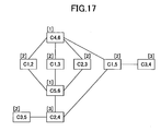
- FIG. 17 is a diagram showing a chromatic graph with groups of the communication links in which the table shown in FIG. 16B is used.
- a numeral in a bracket [ ] shows the group in FIG. 17. Consequently, in order to solve the exposed terminal problem, radio channel allocation can be performed by using three radio channels (frequencies).
- the frequency determining section 118 determines and allocates a radio channel to each communication link so that the same radio channel is allocated to the communication links in the same group.
- the simplified chromatic graph is described in which graph the communication links C1,5 and C2,4 are not used.
- the chromatic graph can be simplified by another method. Specifically, when the combination of the communication links C1,5 and C4,6, the combination of the communication links C1,5 and C5,6, the combination of the communication links C2,4 and C4,6, and the combination of the communication links C2,4 and C5,6 are deleted from the table shown in FIG. 16A, the chromatic graph can be simplified (actually, the combination of the communication links C1,5 and C4,6 and the combination of the communication links C2,4 and C5,6 are deleted).
- FIG. 18 is a flowchart showing the operations of allocating a radio channel to each group of the communication links according to the present embodiment.
- a first radio station broadcasts an ID of its own radio station (step S1802).
- a second radio station receives the ID of the first radio station, forms neighboring node information (step S1804), and broadcasts an ID of its own radio station and the formed neighboring node information to a third radio station (step S1806).
- the third radio station receives the ID and the neighboring node information from the second radio station, and forms neighboring node information (step S1808).
- step S1810 conditions which generate an exposed terminal problem are calculated, that is, a chromatic graph is formed.
- steps S1812 combinations of communication links in which the conditions generating the exposed terminal problem are analogous are calculated.
- step S1814 the combinations of the communication links are grouped in which combinations the conditions generating the exposed terminal problem are analogous.
- a grouping permission inquiry packet is transmitted to radio stations included in the grouped communication links (step S1816).
- each radio station receives response packets for the grouping permission inquiry packet from other radio stations, the radio station determines whether each of the response packets is to permit the grouping (step S1818). When each of the response packets is to permit the grouping (YES in step S1818), the radio station forms a group of the communication links. When some response packets are not to permit the grouping (NO in step S1818), the radio station does not include the communication links responding no permission in the group of the communication links (step S1822).
- the radio station allocates a radio channel to each of the groups to avoid the exposed terminal problem (step S1824).
- FIG. 19 is a flowchart showing the operations of grouping the communication links according to the second embodiment of the present invention.
- a chromatic graph is formed by neighboring node information (step S1902).
- an analogous list of combinations of communication links is formed (step S1904).
- the analogous list is shown in the table of FIG. 16A.
- the analogous list is rearranged in order of high analogy (step S1906).
- the rearranged analogy list is shown in the table of FIG. 16B.
- step S1908 through step S1924 the processes shown in step S1908 through step S1924 are performed for a combination of a communication link A and a communication link B as an example.
- step S1910 it is determined whether the communication link A is connected with the communication link B.
- step S1912 it is determined whether both the communication links A and B are grouped (step S1912).
- step S1912 When both the communication links A and B are grouped (YES in step S1912) (this state is called Pattern 1), the process returns to step S1908 via step S1924.
- step S1914 When both the communication link A and the communication link B are not grouped (NO in step S1912), it is determined whether either the communication link A or the communication link B is grouped (step S1914).
- step S1914 When either the communication link A or the communication link B is not grouped (NO in step S1914), a group in which a communication link is set is searched for to which communication link the communication link A and the communication link B are connected (step S1916), and the communication link A and the communication link B are set in the same group (step S1918). Next, the process returns to step S1908 via step S1924, and the same processes are applied to other communication links other than the communication links A and B.
- step S1914 When either the communication link A or the communication link B is grouped with a communication link (YES in step S1914), in this case, it is defined that a communication link X is grouped with the communication link A or B and a communication link Y is not grouped with the communication link A or B, and it is determined whether the communication link Y is connected to a communication link in a group to which the communication link X belongs (step S1920).
- step S1920 When the communication link Y is connected to a communication link belonging to a group to which the communication link X belongs (YES in step S1920), (Pattern 2), the process returns to step S1908 via step S1924, and processes are applied to another combination of communication links.
- step S1920 When the communication link Y is not connected to a communication link belonging to a group to which the communication link X belongs (NO in step S1920), the communication link Y is set in the same group as the communication link X (step S1922). Then, the process returns to step S1908 via step S1924, and processes are applied to another combination of communication links.
- steps S1914 and S1920 it is defined that the communication link X is grouped with the communication link A or B and the communication link Y is not grouped with the communication link A or B; however, the following steps can be used. That is, it is determined whether the communication link A is grouped with a communication link, and it is determined whether the communication link B is grouped with a communication link belonging to a group of the communication link A.
- FIG. 20 is a graph showing an effect according to the second embodiment of the present invention. Referring to FIG. 20, the effect is described when radio channels (frequencies) are allocated to corresponding grouped communication links.
- radio channels Frequencies
- FIG. 20 in the horizontal axis, it shows the number of nodes in a mesh network, and in the vertical axis, it shows the ratio of radio channel allocation performed by the minimum number of radio channels to that performed by centralized control.
- Non-Clustered is a characteristic in which radio channels are allocated to corresponding communication links without grouping. That is, a radio channel is allocated to a communication link without grouping analogous communication links, and a changing process of a radio channel allocated to a terminal (node) relating to an exposed terminal problem is randomly performed by each node. Consequently, since the radio channels are not allocated by obtaining the total structure of the mesh network, when the number of nodes is increased, the number of radio channels is increased.
- the number of radio channels is the same as that in centralized control; however, in approximately remaining 40% allocation, the number of radio channels is increased when the number of radio channels is compared with that in the centralized control.
- “Clustered” is a characteristic in which radio channels are allocated to corresponding communication links according to the second embodiment of the present invention.
- the characteristic is compared with that shown in “Non-Clustered”
- the increase of the number of radio channels is restrained. For example, in a case where the number of nodes is 10, in approximately 80% allocation, the number of radio channels is the same as that in centralized control.
- the number of radio channels to be allocated can be decreased by using the radio channel allocation method according to the second embodiment of the present invention.
- each radio station broadcasts a packet including its own node ID and information of a combination of communication links in which an exposed terminal problem is generated; however the radio station can unicasts the packet.
- the radio station unicasts the packet, the number of data flowing into the network can be decreased and the network can be effectively utilized.
- the present invention is based on Japanese Priority Patent Application No. 2004-171821 filed on June 9, 2004 , and Japanese Priority Patent Application No. 2004-238574 filed on August 18, 2004 , the entire contents of which are hereby incorporated herein by reference.
- the radio channel allocation apparatus, the radio communication system, and the radio channel allocation method according to the present invention can be applied to an autonomous distributed type asynchronous digital radio transmission system in which a virtual carrier sense is performed.
Abstract
Description
- The present invention generally relates to a radio channel allocation apparatus, a radio communication system, and a radio channel allocation method, in which allocation of radio channels is controlled in a radio communication system which performs an autonomous distributed type asynchronous digital radio transmission using a virtual carrier sense.
- In an asynchronous digital radio transmission system in which autonomous distributed control is assumed, radio signals must be transmitted or received between radio stations where the radio signals can reach each station so as to control allocation of radio channels (radio frequencies).
- In a system using a virtual carrier sense, communications are established between radio stations which perform transmission and reception of signals with each other by exchanging "a transmission request signal" and "a preparation completion signal". Another radio station receiving the above signals postpones transmission of "a transmission request signal" based on "a transmission inhibition period" included in the received signal.
- The virtual carrier sense has not been publicly known at the time of applying for a patent of the present invention as far as the applicant of the present invention knows.
- In addition, the applicant could not find any technical report relating to the present invention. Therefore, technical documents relating to the present invention are not described herein.
- However, existing technologies have the following problems.
- Instead of direct communications between radio stations, when a multi-hop transmission is performed in which transmission communications between the radio stations are established by relay operations of another radio station located between the radio stations, transmission throughput is largely degraded.
- FIG. 1 is a diagram showing a collision of transmission request signals in a multi-hop transmission. Referring to FIG. 1, a case is studied. In the case, when a
radio station 13 and aradio station 14 establish communications by exchanging a transmission request signal and a preparation completion signal, aradio station 12 has transmission inhibition conditions. In this case, the transmission request signals from theradio station 13 to theradio stations radio station 11 transmits a transmission request signal to theradio station 12, since theradio station 12 is in the transmission inhibition conditions, theradio station 12 does not transmit a preparation completion signal. Consequently, theradio station 11 repeats transmitting the transmission request signal to theradio station 12. FIG. 2 is a diagram showing transmission inhibition conditions in the multi-hop transmission. - When the transmission inhibition conditions of the
radio station 12 continue while theradio station 11 repeats transmitting the transmission request signal to theradio station 12, theradio station 11 discards data to be transmitted due to impossibility of communications. Consequently, the transmission throughput may be greatly degraded caused by discarding the data. - In addition, in a mesh network in compliance with IEEE 802.11, an exposed terminal problem may be generated due to a positional relationship among radio stations which desire to perform communications.
- In this case, a packet is repeatedly transmitted based on operations stipulated in IEEE 802.11. However, even if repeated transmission of the packet is performed, when communications are not established, it is handled as packet loss. Consequently, communication quality is degraded. FIG. 3A is a diagram showing an exposed terminal problem. In FIG. 3A, a case is described in which communications between
radio stations radio stations radio stations radio stations - When plural usable radio frequencies (channels) exist, the above quality problem can be solved by using a different radio frequency for communications between radio stations from a radio channel for communications between other radio stations. FIG. 3B is a diagram showing a solution to the exposed terminal problem. For example, as shown in FIG. 3B, a radio frequency f2 is used for communications between the
radio stations radio stations - However, when radio frequencies to use are arbitrarily determined between radio stations in the network, the number of radio frequencies becomes large beyond necessity.
- In a preferred embodiment of the present invention, there is provided a radio channel allocation apparatus, a radio communication system, and a radio channel allocation method, in which transmission throughput degradation in a multi-hop transmission can be prevented.
- In addition, according to an embodiment of the present invention, there is provided a radio channel allocation apparatus, a radio communication system, and a radio channel allocation method, in which increase of the number of radio channels (frequencies) can be restrained while solving an exposed terminal problem.
- In order to achieve one or more of these and other advantages, according to one aspect of the present invention, there is provided a radio channel allocation apparatus of a node in a radio communication system which controls to allocate a radio channel between nodes by a virtual carrier sense. The radio channel allocation apparatus includes a node information collecting unit which collects information of a neighboring node to which the node can directly transmit data, and a radio channel determining unit that determines a radio channel. The determined radio channel is allocated to a communication link between a node which has transmission inhibition conditions and another node which does not have the transmission inhibition conditions by communications between predetermined nodes. The determined radio channel is a different radio channel from a radio channel between the predetermined nodes, based on node information of the node and the neighboring node. Therefore, transmission throughput degradation can be prevented.
- According to another aspect of the present invention, there is provided a radio communication system which controls to allocate a radio channel between nodes by a virtual carrier sense. The radio communication system includes a node information collecting unit which collects information of a neighboring node to which a node can directly transmit data, and a radio channel determining unit that determines a radio channel. The determined radio channel is allocated to a communication link between a node which has transmission inhibition conditions and another node which does not have the transmission inhibition conditions by communications between predetermined nodes. The determined radio channel is a different radio channel from a radio channel between the predetermined nodes, based on node information of the node and the neighboring node. Therefore, a multi-hop transmission can be performed by preventing transmission throughput degradation.
- According to another aspect of the present invention, there is provided a radio channel allocation method in a radio communication system which controls to allocate a radio channel between nodes by a virtual carrier sense. The radio channel allocation method includes the steps of collecting information of a neighboring node to which a node can directly transmit data; receiving information of the neighboring node collected at the node at the neighboring node; and determining a radio channel, which is allocated to a communication link between a node which has transmission inhibition conditions and another node which does not have the transmission inhibition conditions by communications between predetermined nodes. The determined radio channel is a different radio channel from a radio channel between the predetermined nodes, based on the received node information. The method further includes the step of transmitting information of the determined radio channel. Therefore, the radio channels can be allocated while preventing transmission throughput degradation.
- According to an embodiment of the present invention, a radio channel allocation apparatus, a radio communication system, and a radio channel allocation method can prevent transmission throughput degradation in a multi-hop transmission.
- Features and advantages of the present invention will become more apparent from the following detailed description when read in conjunction with the accompanying drawings, in which:
- FIG. 1 is a diagram showing a collision of transmission request signals in a multi-hop transmission;
- FIG. 2 is a diagram showing transmission inhibition conditions in the multi-hop transmission;
- FIG. 3A is a diagram showing an exposed terminal problem;
- FIG. 3B is a diagram showing a solution to the exposed terminal problem;
- FIG. 4 is a diagram showing a radio communication system according to a first embodiment of the present invention
- FIG. 5 is a diagram showing a radio station shown in FIG. 4;
- FIG. 6 is a diagram showing the radio communication system in which radio channels are determined according to the first embodiment of the present invention;
- FIG. 7A is a diagram showing a radio communication system in which a six-hop transmission is performed in seven nodes;
- FIG. 7B is a diagram showing relationships among radio channels between nodes in the radio communication system in which the six-hop transmission is performed in the seven nodes;
- FIG. 7C is a diagram showing relationships among the radio channels between the nodes in the radio communication system in which the six-hop transmission is performed in the seven nodes;
- FIG. 8 is a flowchart showing operations of the radio communication system according to the first embodiment of the present invention;
- FIG. 9A is a diagram showing first allocation of radio channels in a nine-hop transmission of a radio communication system;
- FIG. 9B is a diagram showing second allocation of radio channels in a nine-hop transmission of a radio communication system;
- FIG. 9C is a diagram showing third allocation of radio channels in a nine-hop transmission of a radio communication system;
- FIG. 10 is a diagram showing radio channel settings according to a second embodiment of the present invention;
- FIG. 11A is a diagram showing communication links in a mesh network of six nodes;
- FIG. 11B is a diagram showing a chromatic graph obtained from the communication links shown in FIG. 11A;
- FIG. 12A is a diagram showing modified communication links shown in FIG. 11A;
- FIG. 12B is a diagram showing a chromatic graph obtained from the modified communication links shown in FIG. 12A;
- FIG. 13 is a diagram showing the radio station according to the second embodiment of the present invention;
- FIG. 14A is a diagram showing communication links in a mesh network in which six radio stations (nodes) are included;
- FIG. 14B is a diagram showing a chromatic graph obtained from the communication links shown in FIG. 14A;
- FIG. 15A is a modified diagram of FIG. 14A in which some communication links are assumed not to perform communications;
- FIG. 15B is a diagram showing a chromatic graph obtained from the communication links shown in FIG. 15A;
- FIG. 16A is a table showing radio channel settings according to the second embodiment of the present invention;
- FIG. 16B is a table in which the table shown in FIG. 16A is modified;
- FIG. 17 is a diagram showing a chromatic graph with groups of the communication links in which the table shown in FIG 16B is used;
- FIG. 18 is a flowchart showing operations of allocating a radio channel to each group of the communication links according to the second embodiment of the present invention;
- FIG. 19 is a flowchart showing operations of grouping the communication links according to the second embodiment of the present invention; and
- FIG. 20 is a graph showing an effect according to the second embodiment of the present invention.
- In the following, embodiments of the present invention are described with reference to the drawings. In the drawings and description, some elements are the same, and each of the same elements has the same reference number. Therefore, the same description is omitted.
- The transmission throughput degradation in the multi-hop transmission shown in FIGs. 1 and 2 is generated in the following situation. The
radio station 11 intends to transmit data to theradio station 12 which can recognize a transmission situation between theradio stations radio stations radio station 11 cannot recognize the transmission situation between theradio stations - When a radio channel different from a radio channel being used between the
radio stations radio stations - When the radio channels are determined to solve the above problem, in a three-hop transmission, it is determined that a radio channel of a 1st hop is different from that of a 3rd. However, in a four-hop or more transmission, an allocation method of radio channels (frequencies) is not fixed.
- In order to determine a radio channel between radio stations, a list of radio stations is required in which list the radio stations that are connectable with each other are described. Hereinafter, the list is referred to as neighboring node information. The neighboring node information can be formed by the following method. For example, a packet called "Hello Packet" which is a packet exclusively for forming the neighboring node information is broadcast, and a packet responding to the "Hello Packet" is received. As another method, the neighboring node information can be formed by, for example, receiving data transmissions which are performed between other radio stations.
- Next, referring to FIGs. 4 and 5, a radio communication system according to a first embodiment of the present invention is described. FIG. 4 is a diagram showing the radio communication system according to the first embodiment of the present invention. FIG. 5 is a diagram showing a radio station shown in FIG. 4.
- As shown in FIG. 4, the radio communication system according to the first embodiment of the present invention includes
radio stations - As shown in FIG. 5, the
radio station 110 includes a radio channel allocation apparatus. The radio channel allocation apparatus includes a transmitting/receivingsection 111, acontroller 112, a radiochannel setting section 113, a neighboring nodeinformation collecting section 114, and a neighboring nodeinformation forming section 115. The transmitting/receivingsection 111, the radiochannel setting section 113, the neighboring nodeinformation collecting section 114, and the neighboring nodeinformation forming section 115 are connected to thecontroller 112. Thecontroller 112 controls all the sections in the radio channel allocation apparatus. Theradio stations radio station 110; therefore, the same description is omitted. - In the
radio station 110, the neighboring nodeinformation collecting section 114 collects information of neighboring nodes (radio stations) to which theradio station 110 can directly transmit data. For example, the neighboring nodeinformation collecting section 114 in theradio station 110 collects information of theradio stations information forming section 115 forms neighboring node information by using the information collected by the neighboring nodeinformation collecting section 114. For example, the neighboring nodeinformation forming section 115 forms the neighboring node information in which information of theradio stations section 111 transmits the neighboring node information formed by the neighboring nodeinformation forming section 115 to theradio station 120. - In the
radio station 120, when the transmitting/receivingsection 111 receives the neighboring node information from theradio station 110, the neighboring nodeinformation collecting section 114 collects information of neighboring nodes of theradio station 120. For example, the neighboring nodeinformation collecting section 114 collects information of theradio stations - The neighboring node
information forming section 115 of theradio station 120 forms neighboring node information by adding the neighboring node information received from theradio station 110 to the neighboring node information formed by theown radio station 120. For example, the neighboring nodeinformation forming section 115 forms the neighboring node information including the information of theradio stations radio station 110, and the information of theradio stations radio station 120. The transmitting/receivingsection 111 of theradio station 120 transmits the neighboring node information formed by the neighboring nodeinformation forming section 115 to theradio station 130. - In the
radio station 130, when the transmitting/receivingsection 111 receives the neighboring node information from theradio station 120, similar to in theradio station 120, the neighboring nodeinformation collecting section 114 collects information of neighboring nodes of theradio station 130. For example, the neighboring nodeinformation collecting section 114 collects information of theradio stations - The neighboring node
information forming section 115 of theradio station 130 forms neighboring node information by adding the neighboring node information received from theradio station 120 to the neighboring node information formed by theown radio station 130. For example, the neighboring nodeinformation forming section 115 forms neighboring node information including the information of theradio stations radio station 110, the information of theradio stations radio station 120, and the information of theradio stations radio station 130. The transmitting/receivingsection 111 of theradio station 130 transmits the neighboring node information formed by the neighboring nodeinformation forming section 115 to theradio station 140. - FIG. 6 is a diagram showing the radio communication system in which radio channels are determined according to the first embodiment of the present invention. In the
radio station 140, when the transmitting/receivingsection 111 receives the neighboring node information from theradio station 130, as shown in FIG. 6, the radiochannel setting section 113 determines each radio channel which is used between the radio stations from the received neighboring node information. For example, it is determined that aradio channel 1 is between theradio stations radio channel 1 is between theradio stations radio channel 2 is between theradio stations section 111 of theradio station 140 transmits the determined radio channels to theradio station 130 as radio channel setting information. - When the transmitting/receiving
section 111 of theradio station 130 receives the radio channel setting information transmitted from theradio station 140, the radiochannel setting section 113 deletes the radio channel setting information between theradio stations section 111 of theradio station 130 transmits the radio channel setting information in which the radio channel setting information between theradio stations radio station 120. That is, the transmitting/receivingsection 111 of theradio station 130 transmits the radio channel setting information to theradio station 120 in which information theradio channel 1 is between theradio stations radio channel 1 is between theradio stations - When the transmitting/receiving
section 111 of theradio station 120 receives the radio channel setting information transmitted from theradio station 130, similar to in theradio station 130, the radiochannel setting section 113 deletes the radio channel setting information between theradio stations section 111 of theradio station 120 transmits the radio channel setting information in which the radio channel setting information between theradio stations radio station 110. That is, the transmitting/receivingsection 111 of theradio station 120 transmits the radio channel setting information in which theradio channel 1 is between theradio stations radio station 110. - In the
radio station 110, when the transmitting/receivingsection 111 receives the radio channel setting information from theradio station 120, the radiochannel setting section 113 sets the radio channel corresponding to the received radio channel setting information. That is, the radiochannel setting section 113 sets that the radio channel between theradio stations radio channel 1. - In each of the
radio stations channel setting section 113 sets the radio channel corresponding to the received radio channel setting information. That is, the radiochannel setting section 113 of theradio station 120 sets that the radio channel between theradio stations radio channel 1 and the radiochannel setting section 113 of theradio station 130 sets that the radio channel between theradio stations radio channel 2. - Next, referring to FIG. 7A through 7C, determination of the radio channels being performed by the radio
channel setting section 113 is described. FIG. 7A is a diagram showing a radio communication system in which a six-hop transmission is performed in seven nodes (radio stations). In FIG. 7A, a circled number shows a node and an arrow shows a communication link between the nodes. - In FIG. 7A, in addition to that radio waves are transmitted between neighboring two nodes, the radio waves are transmitted between the
nodes nodes - For example, when communications between the
nodes node 1 reach thenodes - When a destination radio station is determined to be, for example, the
node 2, a connection (communication link) between thenodes 2 and another node on communication links is defined as a connection A, and one of the connections other than the connection A on the communication links is defined as a connection B. For example, thenode 2 determines that a connection between thenodes nodes - In any one of the following cases, the destination station determines that the connection A uses a different radio channel from a radio channel which is used in the connection B. In a first case, radio waves from a transmission station or a reception station in the connection A reach a transmission station in the connection B, and the radio waves neither from the transmission station nor the reception station in the connection A reach a reception station in the connection B. In a second case, the radio waves from the transmission station or the reception station in the connection A reach the reception station in the connection B, and the radio waves neither from the transmission station nor the reception station in the connection A reach the transmission station in the connection B. In a third case, the radio waves from the transmission station or the reception station in the connection B reach the transmission station in the connection A, and the radio waves neither from the transmission station nor the reception station in the connection B reach the reception station in the connection A. In a fourth case, the radio waves from the transmission station or the reception station in the connection B reach the reception station in the connection A, and the radio waves neither from the transmission station nor the reception station in the connection B reach the transmission station in the connection A.
- For example, as described above, the
node 2 determines that the connection between thenodes nodes node 2 determines whether the connections A and B accommodate any one of the following cases. In a first case, radio waves from thenode node 4 in the connection B, and the radio waves neither from thenode 1 nor thenode 2 in the connection A reach thenode 5 in the connection B. In a second case, radio waves from thenode node 5, and the radio waves neither from thenode 1 nor thenode 2 reach thenode 4. In a third case, radio waves from thenode node 1, and the radio waves neither from thenode 4 nor thenode 5 reach thenode 2. In a fourth case, radio waves from thenode node 2, and the radio waves neither from thenode 4 nor thenode 5 reach thenode 1. - In this case, the first case is accommodated, that is, the radio waves from the
node 1 or thenode 2 reach thenode 4, and the radio waves neither from thenode 1 nor thenode 2 reach thenode 5. Therefore, it is determined that the radio channel between thenodes nodes - In addition, when it is determined that the connection between the
nodes nodes node 1 or thenode 2 reach thenode 7, and the radio waves neither from thenode 1 nor thenode 2 reach thenode 6. Therefore, it is determined that the radio channel between thenodes nodes - The above processes are applied to all the connections (communication links) between the
nodes nodes nodes nodes - FIG. 7B is a diagram showing relationships among radio channels between nodes in the radio communication system in which the six-hop transmission is performed in the seven nodes. In FIG. 7B, circled numbers are nodes and arrows are connections (communication links) between the nodes, and a radio channel between nodes "n" and "m" is Cm,n (each of n and m is a different integer). In addition, in FIG. 7B, S1(k) is "true" when a carrier of the node "k" can be sensed at a node "l", that is, S1(k) is "true" when radio waves of the node "k" can reach the node "l". Further, in the right side of FIG. 7B, radio channels which must be different from each other are shown, for example, in the upper part of FIG. 7B, the radio channel C1,2 is different from the radio channel C4,5, and the radio channel C1,2 is different from the radio channel C6,7. This case is described in FIG. 7A.
- When the above cases used in FIG. 7A are applied to FIG. 7B, as shown in the middle part of FIG. 7B, a radio channel between the
nodes nodes nodes nodes nodes - FIG. 7C is a diagram showing relationships among radio channels between nodes in a radio communication system in which a six-hop transmission is performed in seven nodes. In FIG. 7C, the determined results of FIGs. 7A and 7B are described. In addition, in FIG. 7C, a radio channel between nodes "n" and "m" is Cm,n (each of n and m is a different integer), an arrow shows a relationship between the radio channels, and the relationship signifies that the radio channels must be different from each other.
- In FIG. 7C, for example, a connection between the
nodes nodes nodes - As described above, when a first radio channel is used between first and second radio stations and the first radio channel generates transmission inhibition conditions in a third radio station which uses the first radio channel between the third radio station and a fourth radio station, the first radio channel between the third and fourth radio stations is determined to be a different radio channel from the first radio channel based on the neighboring node information. With this, the transmission throughput degradation can be prevented and the number of radio channels to be allocated can be small.
- FIG. 8 is a flowchart showing operations of the radio communication system according to the first embodiment of the present invention. Referring to FIG. 8, the operations of the radio communication system according to the first embodiment of the present invention are described.
- First, the
radio station 110 collects information of neighboring nodes of theradio station 110, forms neighboring node information by using the collected information (step S702), and transmits the formed neighboring node information to the radio station 120 (step S704). - The
radio station 120 receives the neighboring node information from theradio station 110, collects information of neighboring nodes of the radio station 120 (step S706), forms neighboring node information by adding the collected information to the neighboring node information received from the radio station 110 (step S708), and transmits the formed neighboring node information to the radio station 130 (step S710). - The
radio station 130 receives the neighboring node information from theradio station 120, collects information of neighboring nodes of the radio station 130 (step S712), forms neighboring node information by adding the collected information to the neighboring node information received from the radio station 120 (step S714), and transmits the formed neighboring node information to the radio station 140 (step S716). - The
radio station 140 receives the neighboring node information from theradio station 130, and determines radio channels between corresponding radio stations based on the received neighboring node information of all the radio stations on communication links by referring to the processes shown in FIGs. 7A through 7C (step S718). Then, theradio station 140 transmits the determined radio channels to theradio station 130 as radio channel setting information (step S720). - The
radio station 130 receives the radio channel setting information from theradio station 140, sets a radio channel between theradio stations 130 and 140 (S722), and deletes the radio channel setting information between theradio stations radio station 130 transmits the radio channel setting information in which the radio channel setting information between theradio stations - Similarly, the
radio station 120 receives the radio channel setting information from theradio station 130, sets a radio channel between theradio stations 120 and 130 (S728), and deletes the radio channel setting information between theradio stations radio station 120 transmits the radio channel setting information in which the radio channel setting information between theradio stations - The
radio station 110 receives the radio channel setting information from theradio station 120, and sets a radio channel between theradio stations - In the present embodiment, in some radio stations, a radio station collects the neighboring node information of its own radio station after receiving the neighboring node information from a preceding radio station. However, the radio station can collect the neighboring node information of its own radio station beforehand. In this case, the time needed to set the radio channel can be shortened.
- In a radio communication system in which a radio channel is shared among communication links by using autonomous distributed control, frequency utilizing efficiency in which the same radio channel is used between neighboring radio stations is not decreased. However, when the same radio channel is used among the communication links located at a distance, the frequency utilizing efficiency may be largely decreased. As described above, in a radio channel allocation method according to the present embodiment, it is basically different from a concept that communications among neighboring radio stations are performed by simply using different radio channels.
- In FIG. 8, the radio communication system which performs a three-hop transmission by using four radio stations is described. When the present embodiment is applied to a radio communication system using five or more radio stations, the transmission throughput degradation in a multi-hop transmission can be prevented.
- FIGs. 9A through 9C are diagrams showing radio channel settings in a radio communication system of a nine-hop transmission according to the first embodiment of the present invention. Referring to FIGs. 9A through 9C, as an example, combinations of different radio channel settings in the nine-hop transmission are described. In each of FIGs. 9A, 9B, and 9C, a different combination of radio channel settings is shown, and a square shows a radio channel in a communication link between nodes. In FIGs. 9A through 9C, a different radio channel (frequency) must be allocated in each of the radio channels connected by a line, and each radio channel has a pattern, where the same radio channel has the same pattern. In FIGs. 9A and 9B, the necessary number of radio channels is two, and in FIG. 9C, the necessary number of radio channels is three, by the patterns. In the above structure, the number of radio channels to be allocated can be small.
- The first embodiment of the present invention is not limited to the above specific embodiment and can be applied to any communication links between nodes (radio stations).
- Next, a radio communication system according to a second embodiment of the present invention is described.
- In the radio communication system according to the second embodiment of the present invention, the above radio channel allocation method is applied to a mesh network, and can be applied to both an autonomous distributed control system and a centralized control system.
- First, a diagram is described in which diagram communication links are connected and therebetween an exposed terminal problem may be generated. Hereinafter, the diagram is referred to as a chromatic graph.
- FIG. 10 is a diagram showing radio channel settings according to the second embodiment of the present invention. Referring to FIG. 10, a criterion for whether an exposed terminal problem is generated among the following communication links is described. That is, in predetermined nodes k, 1, m, and n, a communication link Ck,l between the nodes k and 1 and a communication link Cm,n between the nodes m and n exist, and the criterion for whether the exposed terminal problem is generated between the communication link Ck,l and the communication link Cm,n is described.
- In two-way communications of TCP, when it is to be determined whether a combination of communication links relates to an exposed terminal problem, the criterion is whether a carrier can be sensed between the nodes k and 1, and whether a carrier can be sensed between the nodes m and n. When conditions S(k,m) are defined in which conditions a carrier from the node m to the node k can be sensed at the node k, the criterion (conditional expression) is:
if [{S(k,m) or S(k,n)} ≠ {S(l,m) or S(l,n)}] or
[{S(k,m) or S(l,m)} ≠ {S(k,n) or S(l,n)}] = TRUE or
FALSE. When the criterion is TRUE, an exposed terminal problem is generated. - For example, (1) when carriers from the nodes m and n cannot be sensed at the node k and a carrier from the node m or n can be sensed at the
node 1, the nodes m and n cannot know about a transmission inhibition period corresponding to transmission of a signal from the node k to thenode 1. Therefore, an exposed terminal problem is generated when a signal is transmitted from the node m or n to thenode 1. - In addition, (2) when carriers from the nodes k and 1 cannot be sensed at the node m and a carrier from the node k or 1 can be sensed at the node n, the nodes k and 1 cannot know about a transmission inhibition period corresponding to transmission of a signal from the node m to the node n. Therefore, an exposed terminal problem is generated when a signal is transmitted from the node k or 1 to the node n.
- Therefore, when the conditional expression is TRUE (the exposed terminal problem may be generated) in the above communications (1) or (2), the relationship between the communication links Ck,l and Cm,n is determined to be a connection relationship in which an exposed terminal problem is generated between the communication links, by using the chromatic graph.
- On the other hand, when both the transmission radio station and the reception radio station can know about the transmission inhibition period or both the radio stations cannot know about the transmission inhibition period by communications therebetween (that is, when both the radio stations cannot communicate with each other) (the conditional expression is FALSE), the relationship between the communication links Ck,l and Cm,n is determined to be a connection relationship in which an exposed terminal problem is not generated between the communication links, by using the chromatic graph. When the above determination is applied to communications between all the communication links, all connection relationships between the communication links can be expressed on the chromatic graph. The present embodiment is not limited to TCP and can be applied to other protocols. In addition, the present embodiment is not limited to two-way communications and can be applied to one-way communications.
- Next, referring to FIGs 11A and 11B, a chromatic graph in a mesh network is described.
- FIG. 11A is a diagram showing communication links in a mesh network of six nodes. FIG. 11B is a diagram showing a chromatic graph obtained from the communication links shown in FIG. 11A.
- In FIG. 11A, communications links exist between
nodes node 1 and anode 3, between thenodes node 1 and anode 5, between thenode 2 and anode 6, between thenode 3 and anode 4, between thenodes nodes nodes - Data transmission can be performed on all the communication links. That is, a carrier sense can be performed on all the communication links.
- In this case, the chromatic graph is formed as shown in FIG. 11B, and radio channel allocation to avoid an exposed terminal problem can be performed by utilizing the chromatic graph.
- In FIG. 11B, combinations of the communication links in which an exposed terminal problem may be generated are as follows. The combination of communication links C2,3 and C4,5, the combination of communication links C2,3 and C5,6, the combination of communication links C2,3 and C1,5, the combination of communication links C4,5 and C1,2, the combination of communication links C4,5 and C2,6, the combination of communication links C5,6 and C1,3, the combination of communication links C5,6 and C3,4, the combination of communication links C1,3 and C2,6, the combination of communication links C1,3 and C4,6, the combination of communication links C1,5 and C4,6, the combination of communication links C4,6 and C1,2, and the combination of communication links C3,4 and C1,2.
- In the mesh network, the number of the communication links is exponentially increased corresponding to an increase of the number of nodes. In addition, the chromatic graph becomes complex and the number of the radio channels to be required to avoid the exposed terminal problem is larger than that in a multi-hop transmission.
- In an actual mesh network, a data transmission using communication links in which a path loss is relatively large is effectively prohibited so as not to degrade the throughput and so as to increase the total amount to be processed.
- FIG. 12A is a diagram showing modified communication links shown in FIG. 11A. FIG. 12B is a diagram showing a chromatic graph obtained from the modified communication links shown in FIG. 12A. For example, as shown in FIG. 12A, when data transmission using the communication links between the
nodes nodes - Next, referring to FIG. 13, a radio station according to the second embodiment of the present invention is described. FIG. 13 is a diagram showing the radio station according to the second embodiment of the present invention. In FIG. 13, a
radio station 110 has the same reference number as that in the first embodiment; however the structure is different from that in the first embodiment. - The
radio station 110 according to the present embodiment includes a radio channel allocation apparatus. The radio channel allocation apparatus includes a transmitting/receivingsection 111, acontroller 112, a radiochannel setting section 113, a neighboring nodeinformation collecting section 114, and a neighboring nodeinformation forming section 115. The transmitting/receivingsection 111, the radiochannel setting section 113, the neighboring nodeinformation collecting section 114, and the neighboring nodeinformation forming section 115 are connected to thecontroller 112. Thecontroller 112 controls all sections in the radio channel allocation apparatus. The radiochannel setting section 113 includes an analogouslink determining section 116, alink grouping section 117, and afrequency setting section 118. The structure of the radiochannel setting section 113 is different from that in the first embodiment. Each of other radio stations in the mesh network has the same structure as that of theradio station 110. - First, in order to form neighboring node information, the neighboring node
information forming section 115 broadcasts a packet via thecontroller 112 and the transmitting/receivingsection 111, in which packet information of its own radio station such as an ID of the own radio station, a using frequency in the own radio station, and neighboring node information of the own radio station are included. - In a radio station received the packet, the neighboring node
information collecting section 114 collects information of the neighboring nodes. In addition, the neighboring nodeinformation forming section 115 forms neighboring node information by adding neighboring node information of its own radio station to the received neighboring node information and broadcasts a packet in which information of its own radio station and the formed neighboring node information are included. When the above processes are repeated, the neighboring nodeinformation collecting section 114 of each radio station can collect information of neighboring nodes. - Further, the neighboring node
information forming section 115 in each radio station forms a chromatic graph based on the formed neighboring node information and estimates combinations of communication links in which an exposed terminal problem may be generated. Specifically, combinations of communication links in which an exposed terminal problem may be generated are estimated based on the following basis. That is, in a case where both a transmission station and a reception station on a communication link (communication link A) which is recognized by the neighboring node information are out of a communication range with another radio station (radio station B) which is recognized by the neighboring node information, an exposed terminal problem is generated in communications between its own radio station and the radio station B during communications on the communication link A. - In order to efficiently perform a frequency change to solve the exposed terminal problem, the following operations are performed.
- The neighboring node
information forming section 115 in each radio station estimates a combination of communication links in which an exposed terminal problem may be generated based on the formed neighboring node information and broadcasts a packet including the estimated result. - Each radio station recognizes all combinations of communication links, in which the exposed terminal problem may be generated, surrounding its own radio station by referring to the combinations of the communication links in which the exposed terminal problem may be generated included in the broadcast packet.
- The analogous
link determining section 116 in each radio station recognizes the combinations of the communication links, in which the exposed terminal problem may be generated, surrounding its own radio station and searches combinations of communication links having a common point (common communication link) with which communication link an exposed terminal problem may be generated, and determines the combinations of the communication links in which the exposed terminal problem may be generated. That is, the analogouslink determining section 116 searches for a combination of communication links having a common point in which an exposed terminal problem may be generated from the combinations of the communication links. Thelink grouping section 117 forms a group of communication links, and grouping of the communication links is described below in detail. - For example, referring to FIGs. 14A and 14B, the above is described in detail. FIG. 14A is a diagram showing communication links in a mesh network in which six radio stations (nodes) are included. In FIG. 14A, a circled number shows a node and a continuous line shows a communication link between nodes. FIG. 14B is a diagram showing a chromatic graph obtained from the communication links shown in FIG. 14A. In FIG. 14B, a rectangle shows a communication link and a continuous line shows a combination of the communication links in which an exposed terminal problem may be generated.
- In FIG. 14A, communications links exist between
nodes node 1 and anode 3, between thenode 1 and anode 5, between thenodes node 2 and anode 4, between thenodes nodes node 4 and anode 6, and between thenodes - Each node forms neighboring node information. Then, each node estimates a combination of communication links in which an exposed terminal problem may be generated based on the above conditions of the combination of the communication links in which the exposed terminal problem may be generated. The conditions are used to allocate different frequencies to corresponding communication links to be connected. Based on the estimation, the chromatic graph shown in FIG. 14B is formed.
- In FIG. 14B, restriction on a frequency allocating to communication links exists in a combination of the communication links C4,6 and C1,2, a combination of the communication links C4,6 and C1,3, a combination of the communication links C4,6 and C2,3, a combination of the communication links C4,6 and C1,5, a combination of the communication links C5,6 and C1,2, a combination of the communication links C5,6 and C1,3, a combination of the communication links C5,6 and C2,3, a combination of the communication links C5,6 and C2,4, a combination of the communication links C1,5 and C2,4, a combination of the communication links C1,5 and C3,4, and a combination of the communication links C2,4 and C3,5.
- In a radio communication network in which radio stations (nodes) connect with each other, when radio waves reach the radio stations, the radio stations can perform communications by using a communication route different from a direct communication route. For example, communications between the
nodes node 3 instead of using the direct communication route. In this case, the chromatic graph can be simplified by assuming that the communications are performed by not using the direct communication route. - FIG. 15A is a modified diagram of FIG. 14A in which some communication links are assumed not to perform communications. In FIG. 15A, for example, the communication links between the
nodes nodes - The chromatic graph of the radio stations may become a part of the chromatic graph shown in FIG. 14B due to the size of the radio communication network or the transfer of the neighboring node information. However, in the following, a case is described in which case all the radio stations share all information on the chromatic graph. Even in a case where each radio station shares a part of the information on the chromatic graph, the following processes are not changed.
- The analogous
link determining section 116 searches for the number of communication links which are common in each combination of the communication links shown in a chromatic graph. However, when combinations of communication links are connected with each other, the number is not searched for. FIG. 16A is a table showing radio channel settings according to the second embodiment of the present invention. The table shown in FIG. 16A is based on the chromatic graph shown in FIG. 14B. In FIG. 16A, the score shows the number of the combinations of the communication links which are common in each combination of the communication links, and "-" in the score shows that a combination of communication links is directly connected. In the search of the number, a common communication link is specified and it is confirmed whether a combination of communication links is connected. That is, FIG. 16A is an analogous list of combinations of communication links. - In the calculation of the score, the following method can be used. The analogous
link determining section 116 calculates the score in the following operations when a predetermined communication link is defined as AA and communication links other than AA are defined as BB. That is, when both the AA and BB generate an exposed terminal problem in another communication link, a predetermined value is added to evaluation variables of AA and BB; when a communication link which generates an exposed terminal problem with AA does not generate the exposed terminal problem with BB, a predetermined value is subtracted from the evaluation variable of AA; and when a communication link which generates an exposed terminal problem with BB does not generate the exposed terminal problem with AA, a predetermined value is subtracted from the evaluation variable of BB. - The analogous
link determining section 116 determines a common communication link in which an exposed terminal problem is generated based on the calculated score. In the present embodiment, the subtraction is not performed and when both the AA and BB generate an exposed terminal problem with another communication link, 1 is added to evaluation variables of AA and BB; with this the score is calculated. In this case, the score becomes the number of the common communication links. - Next, the analogous
link determining section 116 removes the combinations of the communication links in which the score cannot be calculated or is "0" and rearranges the table in a predetermined order. For example, the table is rearranged in order of high score and removes the connection relationship. With this, a table shown in FIG. 16B is obtained. FIG. 16B is the table in which the table shown in FIG. 16A is modified. In FIG. 16B, two cases are shown in PATTERN. That is, a case in which a radio channel can be allocated and another case in which a radio channel cannot be allocated. In the case that a radio channel can be allocated, allocation contents are shown, and in the case where a radio channel cannot be allocated, two conditions "Pattern 1" and "Pattern 2" (described below) are shown. PATTERN in FIG. 16B is described below in detail. In FIG. 16B, a numeral in PATTERN shows a group and is described below in detail. - The
link grouping section 117 forms a group of communication links based on the table shown in FIG. 16B, for example, forms the group in order of high score. For example, thelink grouping section 117 forms a first group from the communication links C4,6 and C5,6 in which the score is three. Next, regarding the communication links C1,2 and C1,3 in which the score is two, since a communication link belonging to the first group exists in a communication link connected to the C1,2 or C1,3, the C1,2 and C1,3 are formed as a second group. - Next, regarding the communication links C1,2 and C2,3, the C1,2 belongs to the second group and the C2,3 is not connected to the other communication link C1,3 in the second group; therefore, the C2,3 is determined to be set in the second group. Next, regarding the communication links C1,3 and C2,3, since both the C1,3 and C2,3 are in the second group, a new group is not formed.
- Next, regarding the communication links C1,2 and C1,5, similar to the case of the C1,2 and C2,3, the C1,5 is determined to be set in the second group. Next, regarding the combination of communication links C1,2 and C2,4, the C1,2 belongs to the second group but the C2,4 is connected to the other communication link C1,5 in the second group; therefore, the C2,4 is determined not to be set in any group. Similarly, when the above is applied to all the communication links, grouping of the communication links is completed. In the present embodiment, as shown in FIG. 17, the communication links form three groups. FIG. 17 is a diagram showing a chromatic graph with groups of the communication links in which the table shown in FIG. 16B is used. A numeral in a bracket [ ] shows the group in FIG. 17. Consequently, in order to solve the exposed terminal problem, radio channel allocation can be performed by using three radio channels (frequencies).
- Next, the
frequency determining section 118 determines and allocates a radio channel to each communication link so that the same radio channel is allocated to the communication links in the same group. - In FIG. 15B, the simplified chromatic graph is described in which graph the communication links C1,5 and C2,4 are not used. However, the chromatic graph can be simplified by another method. Specifically, when the combination of the communication links C1,5 and C4,6, the combination of the communication links C1,5 and C5,6, the combination of the communication links C2,4 and C4,6, and the combination of the communication links C2,4 and C5,6 are deleted from the table shown in FIG. 16A, the chromatic graph can be simplified (actually, the combination of the communication links C1,5 and C4,6 and the combination of the communication links C2,4 and C5,6 are deleted).
- Next, referring to FIGs. 18 and 19, operations of radio stations according to the second embodiment of the present invention are described. First, operations of allocating a radio channel to each group of the communication links according to the present embodiment are described. FIG. 18 is a flowchart showing the operations of allocating a radio channel to each group of the communication links according to the present embodiment.
- First, a first radio station broadcasts an ID of its own radio station (step S1802). A second radio station receives the ID of the first radio station, forms neighboring node information (step S1804), and broadcasts an ID of its own radio station and the formed neighboring node information to a third radio station (step S1806). The third radio station receives the ID and the neighboring node information from the second radio station, and forms neighboring node information (step S1808).
- Next, conditions which generate an exposed terminal problem are calculated, that is, a chromatic graph is formed (step S1810). Next, combinations of communication links in which the conditions generating the exposed terminal problem are analogous are calculated (step S1812). Next, the combinations of the communication links are grouped in which combinations the conditions generating the exposed terminal problem are analogous (step S1814). Then, a grouping permission inquiry packet is transmitted to radio stations included in the grouped communication links (step S1816).
- When each radio station receives response packets for the grouping permission inquiry packet from other radio stations, the radio station determines whether each of the response packets is to permit the grouping (step S1818). When each of the response packets is to permit the grouping (YES in step S1818), the radio station forms a group of the communication links. When some response packets are not to permit the grouping (NO in step S1818), the radio station does not include the communication links responding no permission in the group of the communication links (step S1822).
- Next, the radio station allocates a radio channel to each of the groups to avoid the exposed terminal problem (step S1824).
- Next, referring to FIG. 19, operations of grouping the communication links according to the second embodiment of the present invention are described. FIG. 19 is a flowchart showing the operations of grouping the communication links according to the second embodiment of the present invention.
- First, a chromatic graph is formed by neighboring node information (step S1902). Next, an analogous list of combinations of communication links is formed (step S1904). The analogous list is shown in the table of FIG. 16A. Then, the analogous list is rearranged in order of high analogy (step S1906). The rearranged analogy list is shown in the table of FIG. 16B.
- Next, the following processes are repeated for all the combinations of the communication links (step S1908 through step S1924). First, the processes shown in step S1908 through step S1924 are performed for a combination of a communication link A and a communication link B as an example. First, it is determined whether the communication link A is connected with the communication link B (step S1910). When the communication link A is connected with the communication link B (YES in S1910), the process returns to step S1908 via step S1924. When the communication link A is not connected with the communication link B (NO in S1910), it is determined whether both the communication links A and B are grouped (step S1912).
- When both the communication links A and B are grouped (YES in step S1912) (this state is called Pattern 1), the process returns to step S1908 via step S1924. When both the communication link A and the communication link B are not grouped (NO in step S1912), it is determined whether either the communication link A or the communication link B is grouped (step S1914).
- When either the communication link A or the communication link B is not grouped (NO in step S1914), a group in which a communication link is set is searched for to which communication link the communication link A and the communication link B are connected (step S1916), and the communication link A and the communication link B are set in the same group (step S1918). Next, the process returns to step S1908 via step S1924, and the same processes are applied to other communication links other than the communication links A and B.
- When either the communication link A or the communication link B is grouped with a communication link (YES in step S1914), in this case, it is defined that a communication link X is grouped with the communication link A or B and a communication link Y is not grouped with the communication link A or B, and it is determined whether the communication link Y is connected to a communication link in a group to which the communication link X belongs (step S1920).
- When the communication link Y is connected to a communication link belonging to a group to which the communication link X belongs (YES in step S1920), (Pattern 2), the process returns to step S1908 via step S1924, and processes are applied to another combination of communication links.
- When the communication link Y is not connected to a communication link belonging to a group to which the communication link X belongs (NO in step S1920), the communication link Y is set in the same group as the communication link X (step S1922). Then, the process returns to step S1908 via step S1924, and processes are applied to another combination of communication links.
- In steps S1914 and S1920, it is defined that the communication link X is grouped with the communication link A or B and the communication link Y is not grouped with the communication link A or B; however, the following steps can be used. That is, it is determined whether the communication link A is grouped with a communication link, and it is determined whether the communication link B is grouped with a communication link belonging to a group of the communication link A.
- FIG. 20 is a graph showing an effect according to the second embodiment of the present invention. Referring to FIG. 20, the effect is described when radio channels (frequencies) are allocated to corresponding grouped communication links. In FIG. 20, in the horizontal axis, it shows the number of nodes in a mesh network, and in the vertical axis, it shows the ratio of radio channel allocation performed by the minimum number of radio channels to that performed by centralized control.
- In FIG. 20, "Non-Clustered" is a characteristic in which radio channels are allocated to corresponding communication links without grouping. That is, a radio channel is allocated to a communication link without grouping analogous communication links, and a changing process of a radio channel allocated to a terminal (node) relating to an exposed terminal problem is randomly performed by each node. Consequently, since the radio channels are not allocated by obtaining the total structure of the mesh network, when the number of nodes is increased, the number of radio channels is increased. For example, in a case where the number of nodes is 10, in approximately 60% allocation, the number of radio channels is the same as that in centralized control; however, in approximately remaining 40% allocation, the number of radio channels is increased when the number of radio channels is compared with that in the centralized control.
- In FIG. 20, "Clustered" is a characteristic in which radio channels are allocated to corresponding communication links according to the second embodiment of the present invention. When the characteristic is compared with that shown in "Non-Clustered", the increase of the number of radio channels is restrained. For example, in a case where the number of nodes is 10, in approximately 80% allocation, the number of radio channels is the same as that in centralized control.
- As shown in FIG. 20, the number of radio channels to be allocated can be decreased by using the radio channel allocation method according to the second embodiment of the present invention.
- In the second embodiment of the present invention, each radio station broadcasts a packet including its own node ID and information of a combination of communication links in which an exposed terminal problem is generated; however the radio station can unicasts the packet. When the radio station unicasts the packet, the number of data flowing into the network can be decreased and the network can be effectively utilized.
- The present invention is not limited to the specifically disclosed embodiments, and variations and modifications may be made without departing from the scope of the present invention.
- The present invention is based on
Japanese Priority Patent Application No. 2004-171821 filed on June 9, 2004 Japanese Priority Patent Application No. 2004-238574 filed on August 18, 2004 - The radio channel allocation apparatus, the radio communication system, and the radio channel allocation method according to the present invention can be applied to an autonomous distributed type asynchronous digital radio transmission system in which a virtual carrier sense is performed.
Claims (10)
- A radio channel allocation apparatus of a node in a radio communication system which controls to allocate a radio channel between nodes by a virtual carrier sense, comprising:a node information collecting unit which collects information of a neighboring node to which the node can directly transmit data; anda radio channel determining unit that determines a radio channel, which determined radio channel is allocated to a communication link between a node which has transmission inhibition conditions and another node which does not have the transmission inhibition conditions by communications between predetermined nodes, the determined radio channel being a different radio channel from a radio channel between the predetermined nodes, based on node information of the node and the neighboring node.
- The radio channel allocation apparatus as claimed in claim 1, wherein:in a case where it is defined that a predetermined communication link between nodes is A and a communication link between nodes other than the predetermined communication link is B in communication links of data transmission lines,the radio channel determining unit allocates a different radio channel to the communication link A from a radio channel allocated to the communication link B in any one of the following cases,a first case where one of radio waves from a transmission node and a reception node in the communication link A reaches a transmission node in the communication link B, and the radio waves from the transmission node and the reception node in the communication link A do not reach the reception node in the communication link B,a second case where one of the radio waves from the transmission node and the reception node in the communication link A reaches the reception node in the communication link B, and the radio waves from the transmission node and the reception node in the communication link A do not reach the transmission node in the communication link B,a third case where one of radio waves from the transmission node and the reception node in the communication link B reaches the transmission node in the communication link A, and the radio waves from the transmission node and the reception node in the communication link B do not reach the reception node in the communication link A, anda fourth case where one of the radio waves from the transmission node and the reception node in the communication link B reaches the reception node in the communication link A, and the radio waves from the transmission node and the reception node in the communication link B do not reach the transmission node in the communication link A.
- The radio channel allocation apparatus as claimed in claim 1, further comprising:an analogous link determining unit which determines whether a common communication link exists in a combination of communication links based on a predetermined criterion; whereinthe radio channel determining unit determines a radio channel to be allocated to the communication link based on a determined result by the analogous link determining unit.
- The radio channel allocation apparatus as claimed in claim 3, wherein:the analogous link determining unit determines whether a combination of communication links which generates an exposed terminal problem exists.
- The radio channel allocation apparatus as claimed in claim 4, wherein:in a case where nodes k, l, m, and n exist in the radio communication system,the analogous link determining unit determines a combination of a communication link between the nodes k and 1 and a communication link between the nodes m and n as a combination of communication links which generates the exposed terminal problem in one of the following cases,a first case where the node k cannot sense carriers from the nodes m and n, but the node 1 can sense a carrier from the node m or n, anda second case where the node m cannot sense carriers from the nodes k and l, but the node n can sense a carrier from the node k or l.
- The radio channel allocation apparatus as claimed in claim 4, wherein:in a case where it is defined that a predetermined communication link is AA and a communication link other than the predetermined link is BB,the analogous link determining unit determines whether a combination of communication links between the nodes which combination generates the exposed terminal problem exists based on evaluation variables of the AA and the BB which evaluation variables are calculated by the following method,when both the AA and the BB generate the exposed terminal problem in another communication link, a predetermined value is added to the evaluation variables of the AA and the BB,when a communication link generating the exposed terminal problem with the AA does not generate the exposed terminal problem with the BB, a predetermined value is subtracted from the evaluation variable of the AA, andwhen a communication link generating the exposed terminal problem with the BB does not generate the exposed terminal problem with the AA, a predetermined value is subtracted from the evaluation variable of the BB.
- The radio channel allocation apparatus as claimed in claim 3, further comprising:a communication link grouping unit which groups communication links having a common communication link based on the determined result by the analogous link determining unit; whereinthe radio channel determining unit allocates the same radio channel to grouped communication links.
- A radio communication system which controls to allocate a radio channel between nodes by a virtual carrier sense, comprising:a node information collecting unit which collects information of a neighboring node to which a node can directly transmit data; anda radio channel determining unit that determines a radio channel, which determined radio channel is allocated to a communication link between a node which has transmission inhibition conditions and another node which does not have the transmission inhibition conditions by communications between predetermined nodes, the determined radio channel being a different radio channel from a radio channel between the predetermined nodes, based on node information of the node and the neighboring node.
- A radio channel allocation method in a radio communication system which controls to allocate a radio channel between nodes by a virtual carrier sense, comprising the steps of:collecting information of a neighboring node to which a node can directly transmit data;receiving information of the neighboring node collected at the node at the neighboring node;determining a radio channel, which determined radio channel is allocated to a communication link between a node which has transmission inhibition conditions and another node which does not have the transmission inhibition conditions by communications between predetermined nodes, the determined radio channel being a different radio channel from a radio channel between the predetermined nodes, based on the received node information; andtransmitting information of the determined radio channel.
- The radio channel allocation method as claimed in claim 9, further comprising the step of:determining whether a common communication link exists in combinations of communication links based on a predetermined criterion; whereina radio channel to be allocated to the communication link is determined based on the determined result.
Applications Claiming Priority (3)
| Application Number | Priority Date | Filing Date | Title |
|---|---|---|---|
| JP2004171821 | 2004-06-09 | ||
| JP2004238574A JP4391911B2 (en) | 2004-06-09 | 2004-08-18 | Radio frequency allocation device, radio communication system, and radio frequency allocation method |
| PCT/JP2005/010574 WO2005122484A1 (en) | 2004-06-09 | 2005-06-09 | Radio frequency assigning apparatus, wireless communication system, and radio frequency assigning method |
Publications (3)
| Publication Number | Publication Date |
|---|---|
| EP1755277A1 true EP1755277A1 (en) | 2007-02-21 |
| EP1755277A4 EP1755277A4 (en) | 2011-07-27 |
| EP1755277B1 EP1755277B1 (en) | 2013-07-24 |
Family
ID=35503470
Family Applications (1)
| Application Number | Title | Priority Date | Filing Date |
|---|---|---|---|
| EP05748900.7A Expired - Fee Related EP1755277B1 (en) | 2004-06-09 | 2005-06-09 | Radio frequency assigning apparatus, wireless communication system, and radio frequency assigning method |
Country Status (6)
| Country | Link |
|---|---|
| US (1) | US7693525B2 (en) |
| EP (1) | EP1755277B1 (en) |
| JP (1) | JP4391911B2 (en) |
| CN (1) | CN1965538B (en) |
| ES (1) | ES2432367T3 (en) |
| WO (1) | WO2005122484A1 (en) |
Families Citing this family (9)
| Publication number | Priority date | Publication date | Assignee | Title |
|---|---|---|---|---|
| JP4757140B2 (en) * | 2006-08-10 | 2011-08-24 | 株式会社エヌ・ティ・ティ・ドコモ | Radio frequency assignment device, radio communication system, and radio frequency assignment method |
| US7885674B2 (en) * | 2006-08-22 | 2011-02-08 | Cisco Technology, Inc. | Determining which channels are accessible by a communication device in a push-to-talk communication network |
| BRPI0717823A2 (en) | 2006-10-03 | 2014-04-15 | Panasonic Corp | RETRANSMITTER STATION IN MOBILE COMMUNICATION SYSTEM AND AUTOMATIC RETRANSMISSION CHANNEL ADJUSTMENT METHOD |
| US8155139B2 (en) * | 2006-11-07 | 2012-04-10 | Conexant Systems, Inc. | Systems and methods for management of wireless clients |
| JP5066455B2 (en) * | 2008-01-28 | 2012-11-07 | Kddi株式会社 | Wireless communication path determination device and wireless communication path determination method |
| JP5150674B2 (en) * | 2010-03-25 | 2013-02-20 | 株式会社バッファロー | Wireless LAN system, wireless LAN device, setting information setting method and program thereof |
| JP5955627B2 (en) * | 2012-05-02 | 2016-07-20 | シャープ株式会社 | Wireless communication device, wireless communication method, processing device, program |
| US9294158B2 (en) * | 2012-08-07 | 2016-03-22 | Broadcom Corporation | Broadcast audio service |
| CN109155918B (en) * | 2016-05-24 | 2023-05-05 | 奥林巴斯株式会社 | Wireless communication terminal, wireless communication system, wireless communication method, and recording medium |
Citations (1)
| Publication number | Priority date | Publication date | Assignee | Title |
|---|---|---|---|---|
| US20030174690A1 (en) * | 2001-11-02 | 2003-09-18 | At&T Corp. | Wireless LANs and neighborhood capture |
Family Cites Families (14)
| Publication number | Priority date | Publication date | Assignee | Title |
|---|---|---|---|---|
| US6006017A (en) * | 1995-05-02 | 1999-12-21 | Motorola Inc. | System for determining the frequency of repetitions of polling active stations relative to the polling of inactive stations |
| JPH09130853A (en) * | 1995-10-26 | 1997-05-16 | Uniden Corp | Communicating method, communication equipment and cordless telephone system |
| US6310866B1 (en) * | 1998-10-09 | 2001-10-30 | Telefonaktiebolaget Lm Ericsson (Publ) | Medium access control protocol with automatic frequency assignment |
| US7184413B2 (en) * | 1999-02-10 | 2007-02-27 | Nokia Inc. | Adaptive communication protocol for wireless networks |
| US6751455B1 (en) * | 1999-09-17 | 2004-06-15 | The Regents Of The University Of California | Power- and bandwidth-adaptive in-home wireless communications system with power-grid-powered agents and battery-powered clients |
| US7142523B1 (en) * | 2000-07-31 | 2006-11-28 | Lucent Technologies Inc. | Methods and apparatus for design, adjustment or operation of wireless networks using pre-frequency-assignment optimization |
| US6990087B2 (en) * | 2002-04-25 | 2006-01-24 | Raytheon Company | Dynamic wireless resource utilization |
| US7106707B1 (en) * | 2001-12-20 | 2006-09-12 | Meshnetworks, Inc. | System and method for performing code and frequency channel selection for combined CDMA/FDMA spread spectrum communication systems |
| KR100465208B1 (en) * | 2002-04-02 | 2005-01-13 | 조광선 | System, Apparatus, and Method for Wireless Mobile Communication in association with Mobile AD-HOC Network Support |
| CN1417992A (en) * | 2002-11-27 | 2003-05-14 | 北京邮电大学 | Improved medium access contorl protocol of Ad-hoc network based on IEEE802.11 support |
| US7248574B2 (en) * | 2003-02-24 | 2007-07-24 | Autocell Laboratories, Inc. | Apparatus for selecting an optimum access point in a wireless network |
| US7397785B2 (en) * | 2003-05-28 | 2008-07-08 | Nokia Corporation | Method for enhancing fairness and performance in a multihop ad hoc network and corresponding system |
| US7269138B2 (en) * | 2003-06-04 | 2007-09-11 | Motorola, Inc. | Distributed MAC protocol facilitating collaborative ranging in communications networks |
| JP4567605B2 (en) * | 2004-01-30 | 2010-10-20 | 三菱電機株式会社 | Wireless channel allocation method |
-
2004
- 2004-08-18 JP JP2004238574A patent/JP4391911B2/en not_active Expired - Fee Related
-
2005
- 2005-06-09 EP EP05748900.7A patent/EP1755277B1/en not_active Expired - Fee Related
- 2005-06-09 US US11/628,986 patent/US7693525B2/en not_active Expired - Fee Related
- 2005-06-09 WO PCT/JP2005/010574 patent/WO2005122484A1/en not_active Application Discontinuation
- 2005-06-09 CN CN2005800189224A patent/CN1965538B/en not_active Expired - Fee Related
- 2005-06-09 ES ES05748900T patent/ES2432367T3/en active Active
Patent Citations (1)
| Publication number | Priority date | Publication date | Assignee | Title |
|---|---|---|---|---|
| US20030174690A1 (en) * | 2001-11-02 | 2003-09-18 | At&T Corp. | Wireless LANs and neighborhood capture |
Non-Patent Citations (3)
| Title |
|---|
| Padmanabhan, V. ET AL.: "Impact of Interference on Multi-hopWireless Network Performance", Workshop: Robustness in Complex Systems , 28 February 2004 (2004-02-28), page 38PP, XP002638527, Retrieved from the Internet: URL:http://www.ima.umn.edu/talks/workshops/2-9-13.2004/padmanabhan/ima-feb2004.pdf [retrieved on 2011-05-23] * |
| See also references of WO2005122484A1 * |
| ZHENMIN LI ET AL: "Fragmentation based D-MAC protocol in wireless ad hoc networks", PROCEEDINGS OF THE 23RD INTERNATIONAL CONFERENCE ON DISTRIBUTED COMPUTING SYSTEMS. ICDCS 2003. PROVIDENCE, RI, vol. CONF. 23, 19 May 2003 (2003-05-19), - 22 May 2003 (2003-05-22), pages 468-477, XP010642317, IEEE COMP. SOC, US DOI: 10.1109/ICDCS.2003.1203497 ISBN: 978-0-7695-1920-3 * |
Also Published As
| Publication number | Publication date |
|---|---|
| EP1755277B1 (en) | 2013-07-24 |
| JP4391911B2 (en) | 2009-12-24 |
| JP2006025388A (en) | 2006-01-26 |
| WO2005122484A1 (en) | 2005-12-22 |
| CN1965538B (en) | 2010-09-01 |
| ES2432367T3 (en) | 2013-12-03 |
| US7693525B2 (en) | 2010-04-06 |
| EP1755277A4 (en) | 2011-07-27 |
| CN1965538A (en) | 2007-05-16 |
| US20070242650A1 (en) | 2007-10-18 |
Similar Documents
| Publication | Publication Date | Title |
|---|---|---|
| EP1755277B1 (en) | Radio frequency assigning apparatus, wireless communication system, and radio frequency assigning method | |
| US10462808B2 (en) | Method for scheduling transmissions in wireless networks | |
| US10349427B2 (en) | Method for scheduling closed loop information in wireless networks | |
| EP1324509B1 (en) | Packet transmission control method | |
| AU2002313823B2 (en) | System and method for collision-free transmission scheduling using neighborhood information and advertised transmission times | |
| US10368349B2 (en) | Method for assisting bidirectional communication in wireless networks | |
| EP3025557B1 (en) | Transmission unit allocation and use in networks | |
| US20080170544A1 (en) | Method of transmitting between two nodes | |
| CN111818652B (en) | Channel resource allocation method of multi-transceiver multi-channel wireless Ad Hoc network | |
| EP1925131A2 (en) | Method and apparatus for supporting ad-hoc networking over umts (universal mobile telecommunications system) protocol | |
| JP5627816B2 (en) | Communication system, communication terminal, and communication method | |
| AU2002313823A1 (en) | System and method for collision-free transmission scheduling using neighborhood information and advertised transmission times | |
| US7808907B2 (en) | Scheduling method for use in a mesh network | |
| JP2008172283A (en) | Multi-hop radio communication system and configuration method thereof, and radio communication device | |
| Gong et al. | A combined proactive routing and multi-channel MAC protocol for wireless ad hoc networks | |
| CN111866985B (en) | Hybrid relay selection method for dense communication networks | |
| EP2098015B1 (en) | Wireless non-cellular network | |
| KR100839650B1 (en) | Radio frequency assigning apparatus, wireless communication system, and radio frequency assigning method | |
| Sánchez Garache | Multiple access protocols with smart antennas in multihop ad hoc rural-area networks | |
| Kirchhof et al. | Improving MAC protocols for wireless industrial networks via packet prioritization and cooperation | |
| CN113766601A (en) | Self-organizing network cooperative transmission path construction method based on cooperative relay transmission | |
| JP5595982B2 (en) | Wireless communication system and wireless communication method | |
| Li et al. | Research on cross-layer design for MANET | |
| JP2012151565A (en) | Radio communication system | |
| JP2012015794A (en) | Radio communication system |
Legal Events
| Date | Code | Title | Description |
|---|---|---|---|
| PUAI | Public reference made under article 153(3) epc to a published international application that has entered the european phase |
Free format text: ORIGINAL CODE: 0009012 |
|
| 17P | Request for examination filed |
Effective date: 20061207 |
|
| AK | Designated contracting states |
Kind code of ref document: A1 Designated state(s): DE ES FI FR GB IT |
|
| RBV | Designated contracting states (corrected) |
Designated state(s): DE ES FI FR GB IT |
|
| DAX | Request for extension of the european patent (deleted) | ||
| A4 | Supplementary search report drawn up and despatched |
Effective date: 20110624 |
|
| 17Q | First examination report despatched |
Effective date: 20110824 |
|
| REG | Reference to a national code |
Ref country code: DE Ref legal event code: R079 Ref document number: 602005040542 Country of ref document: DE Free format text: PREVIOUS MAIN CLASS: H04L0012280000 Ipc: H04W0072040000 |
|
| GRAP | Despatch of communication of intention to grant a patent |
Free format text: ORIGINAL CODE: EPIDOSNIGR1 |
|
| RIC1 | Information provided on ipc code assigned before grant |
Ipc: H04W 72/04 20090101AFI20130116BHEP Ipc: H04W 84/18 20090101ALN20130116BHEP |
|
| GRAS | Grant fee paid |
Free format text: ORIGINAL CODE: EPIDOSNIGR3 |
|
| GRAA | (expected) grant |
Free format text: ORIGINAL CODE: 0009210 |
|
| AK | Designated contracting states |
Kind code of ref document: B1 Designated state(s): DE ES FI FR GB IT |
|
| REG | Reference to a national code |
Ref country code: GB Ref legal event code: FG4D |
|
| REG | Reference to a national code |
Ref country code: DE Ref legal event code: R096 Ref document number: 602005040542 Country of ref document: DE Effective date: 20130919 |
|
| PLBE | No opposition filed within time limit |
Free format text: ORIGINAL CODE: 0009261 |
|
| STAA | Information on the status of an ep patent application or granted ep patent |
Free format text: STATUS: NO OPPOSITION FILED WITHIN TIME LIMIT |
|
| 26N | No opposition filed |
Effective date: 20140425 |
|
| REG | Reference to a national code |
Ref country code: DE Ref legal event code: R097 Ref document number: 602005040542 Country of ref document: DE Effective date: 20140425 |
|
| REG | Reference to a national code |
Ref country code: FR Ref legal event code: PLFP Year of fee payment: 12 |
|
| REG | Reference to a national code |
Ref country code: FR Ref legal event code: PLFP Year of fee payment: 13 |
|
| REG | Reference to a national code |
Ref country code: FR Ref legal event code: PLFP Year of fee payment: 14 |
|
| PGFP | Annual fee paid to national office [announced via postgrant information from national office to epo] |
Ref country code: DE Payment date: 20180530 Year of fee payment: 14 Ref country code: FI Payment date: 20180612 Year of fee payment: 14 |
|
| PGFP | Annual fee paid to national office [announced via postgrant information from national office to epo] |
Ref country code: FR Payment date: 20180511 Year of fee payment: 14 |
|
| PGFP | Annual fee paid to national office [announced via postgrant information from national office to epo] |
Ref country code: ES Payment date: 20180703 Year of fee payment: 14 Ref country code: GB Payment date: 20180606 Year of fee payment: 14 Ref country code: IT Payment date: 20180625 Year of fee payment: 14 |
|
| REG | Reference to a national code |
Ref country code: DE Ref legal event code: R119 Ref document number: 602005040542 Country of ref document: DE |
|
| REG | Reference to a national code |
Ref country code: FI Ref legal event code: MAE |
|
| PG25 | Lapsed in a contracting state [announced via postgrant information from national office to epo] |
Ref country code: FI Free format text: LAPSE BECAUSE OF NON-PAYMENT OF DUE FEES Effective date: 20190609 |
|
| GBPC | Gb: european patent ceased through non-payment of renewal fee |
Effective date: 20190609 |
|
| PG25 | Lapsed in a contracting state [announced via postgrant information from national office to epo] |
Ref country code: DE Free format text: LAPSE BECAUSE OF NON-PAYMENT OF DUE FEES Effective date: 20200101 Ref country code: IT Free format text: LAPSE BECAUSE OF NON-PAYMENT OF DUE FEES Effective date: 20190609 Ref country code: GB Free format text: LAPSE BECAUSE OF NON-PAYMENT OF DUE FEES Effective date: 20190609 |
|
| PG25 | Lapsed in a contracting state [announced via postgrant information from national office to epo] |
Ref country code: FR Free format text: LAPSE BECAUSE OF NON-PAYMENT OF DUE FEES Effective date: 20190630 |
|
| REG | Reference to a national code |
Ref country code: ES Ref legal event code: FD2A Effective date: 20201027 |
|
| PG25 | Lapsed in a contracting state [announced via postgrant information from national office to epo] |
Ref country code: ES Free format text: LAPSE BECAUSE OF NON-PAYMENT OF DUE FEES Effective date: 20190610 |