EP1755089B1 - Packaging device and container for sheet objects - Google Patents
Packaging device and container for sheet objects Download PDFInfo
- Publication number
- EP1755089B1 EP1755089B1 EP06125453A EP06125453A EP1755089B1 EP 1755089 B1 EP1755089 B1 EP 1755089B1 EP 06125453 A EP06125453 A EP 06125453A EP 06125453 A EP06125453 A EP 06125453A EP 1755089 B1 EP1755089 B1 EP 1755089B1
- Authority
- EP
- European Patent Office
- Prior art keywords
- container
- container according
- opening
- closure member
- sheet
- Prior art date
- Legal status (The legal status is an assumption and is not a legal conclusion. Google has not performed a legal analysis and makes no representation as to the accuracy of the status listed.)
- Expired - Lifetime
Links
- 238000004806 packaging method and process Methods 0.000 title claims description 30
- 238000000034 method Methods 0.000 claims description 7
- 230000008878 coupling Effects 0.000 claims description 6
- 238000010168 coupling process Methods 0.000 claims description 6
- 238000005859 coupling reaction Methods 0.000 claims description 6
- 239000000463 material Substances 0.000 claims description 6
- 239000004033 plastic Substances 0.000 claims description 4
- 229920003023 plastic Polymers 0.000 claims description 4
- 238000007789 sealing Methods 0.000 claims description 4
- 239000000758 substrate Substances 0.000 description 8
- 230000007246 mechanism Effects 0.000 description 7
- 238000003780 insertion Methods 0.000 description 6
- 230000037431 insertion Effects 0.000 description 6
- 239000000123 paper Substances 0.000 description 5
- 230000006835 compression Effects 0.000 description 4
- 238000007906 compression Methods 0.000 description 4
- 238000010200 validation analysis Methods 0.000 description 4
- 239000004020 conductor Substances 0.000 description 3
- 238000010438 heat treatment Methods 0.000 description 3
- 238000012986 modification Methods 0.000 description 3
- 230000004048 modification Effects 0.000 description 3
- 229910000679 solder Inorganic materials 0.000 description 3
- 238000002844 melting Methods 0.000 description 2
- 230000008018 melting Effects 0.000 description 2
- 238000000465 moulding Methods 0.000 description 2
- 230000003287 optical effect Effects 0.000 description 2
- 238000012856 packing Methods 0.000 description 2
- -1 polypropylene Polymers 0.000 description 2
- 238000007639 printing Methods 0.000 description 2
- 229920001169 thermoplastic Polymers 0.000 description 2
- 239000004416 thermosoftening plastic Substances 0.000 description 2
- 238000009461 vacuum packaging Methods 0.000 description 2
- 239000004925 Acrylic resin Substances 0.000 description 1
- 229920000178 Acrylic resin Polymers 0.000 description 1
- 229910000881 Cu alloy Inorganic materials 0.000 description 1
- 241000463291 Elga Species 0.000 description 1
- 239000004593 Epoxy Substances 0.000 description 1
- 239000004698 Polyethylene Substances 0.000 description 1
- 239000004743 Polypropylene Substances 0.000 description 1
- 229910001069 Ti alloy Inorganic materials 0.000 description 1
- 230000005540 biological transmission Effects 0.000 description 1
- 239000003795 chemical substances by application Substances 0.000 description 1
- 230000000994 depressogenic effect Effects 0.000 description 1
- 230000000694 effects Effects 0.000 description 1
- 238000005516 engineering process Methods 0.000 description 1
- 239000000835 fiber Substances 0.000 description 1
- 239000011152 fibreglass Substances 0.000 description 1
- 238000007373 indentation Methods 0.000 description 1
- 238000004519 manufacturing process Methods 0.000 description 1
- 239000000155 melt Substances 0.000 description 1
- 239000002184 metal Substances 0.000 description 1
- 239000002991 molded plastic Substances 0.000 description 1
- 238000003032 molecular docking Methods 0.000 description 1
- 230000002093 peripheral effect Effects 0.000 description 1
- 229920000573 polyethylene Polymers 0.000 description 1
- 229920001155 polypropylene Polymers 0.000 description 1
- 238000012545 processing Methods 0.000 description 1
- 230000001737 promoting effect Effects 0.000 description 1
- 230000000007 visual effect Effects 0.000 description 1
- 239000002699 waste material Substances 0.000 description 1
Images





Classifications
-
- B—PERFORMING OPERATIONS; TRANSPORTING
- B65—CONVEYING; PACKING; STORING; HANDLING THIN OR FILAMENTARY MATERIAL
- B65D—CONTAINERS FOR STORAGE OR TRANSPORT OF ARTICLES OR MATERIALS, e.g. BAGS, BARRELS, BOTTLES, BOXES, CANS, CARTONS, CRATES, DRUMS, JARS, TANKS, HOPPERS, FORWARDING CONTAINERS; ACCESSORIES, CLOSURES, OR FITTINGS THEREFOR; PACKAGING ELEMENTS; PACKAGES
- B65D1/00—Rigid or semi-rigid containers having bodies formed in one piece, e.g. by casting metallic material, by moulding plastics, by blowing vitreous material, by throwing ceramic material, by moulding pulped fibrous material or by deep-drawing operations performed on sheet material
- B65D1/22—Boxes or like containers with side walls of substantial depth for enclosing contents
- B65D1/26—Thin-walled containers, e.g. formed by deep-drawing operations
-
- B—PERFORMING OPERATIONS; TRANSPORTING
- B65—CONVEYING; PACKING; STORING; HANDLING THIN OR FILAMENTARY MATERIAL
- B65B—MACHINES, APPARATUS OR DEVICES FOR, OR METHODS OF, PACKAGING ARTICLES OR MATERIALS; UNPACKING
- B65B25/00—Packaging other articles presenting special problems
- B65B25/14—Packaging paper or like sheets, envelopes, or newspapers, in flat, folded, or rolled form
- B65B25/141—Packaging paper or like sheets, envelopes, or newspapers, in flat, folded, or rolled form packaging flat articles in boxes
-
- B—PERFORMING OPERATIONS; TRANSPORTING
- B65—CONVEYING; PACKING; STORING; HANDLING THIN OR FILAMENTARY MATERIAL
- B65B—MACHINES, APPARATUS OR DEVICES FOR, OR METHODS OF, PACKAGING ARTICLES OR MATERIALS; UNPACKING
- B65B61/00—Auxiliary devices, not otherwise provided for, for operating on sheets, blanks, webs, binding material, containers or packages
- B65B61/02—Auxiliary devices, not otherwise provided for, for operating on sheets, blanks, webs, binding material, containers or packages for perforating, scoring, slitting, or applying code or date marks on material prior to packaging
- B65B61/025—Auxiliary devices, not otherwise provided for, for operating on sheets, blanks, webs, binding material, containers or packages for perforating, scoring, slitting, or applying code or date marks on material prior to packaging for applying, e.g. printing, code or date marks on material prior to packaging
-
- B—PERFORMING OPERATIONS; TRANSPORTING
- B65—CONVEYING; PACKING; STORING; HANDLING THIN OR FILAMENTARY MATERIAL
- B65D—CONTAINERS FOR STORAGE OR TRANSPORT OF ARTICLES OR MATERIALS, e.g. BAGS, BARRELS, BOTTLES, BOXES, CANS, CARTONS, CRATES, DRUMS, JARS, TANKS, HOPPERS, FORWARDING CONTAINERS; ACCESSORIES, CLOSURES, OR FITTINGS THEREFOR; PACKAGING ELEMENTS; PACKAGES
- B65D21/00—Nestable, stackable or joinable containers; Containers of variable capacity
- B65D21/08—Containers of variable capacity
-
- B—PERFORMING OPERATIONS; TRANSPORTING
- B65—CONVEYING; PACKING; STORING; HANDLING THIN OR FILAMENTARY MATERIAL
- B65D—CONTAINERS FOR STORAGE OR TRANSPORT OF ARTICLES OR MATERIALS, e.g. BAGS, BARRELS, BOTTLES, BOXES, CANS, CARTONS, CRATES, DRUMS, JARS, TANKS, HOPPERS, FORWARDING CONTAINERS; ACCESSORIES, CLOSURES, OR FITTINGS THEREFOR; PACKAGING ELEMENTS; PACKAGES
- B65D43/00—Lids or covers for rigid or semi-rigid containers
- B65D43/14—Non-removable lids or covers
- B65D43/16—Non-removable lids or covers hinged for upward or downward movement
- B65D43/162—Non-removable lids or covers hinged for upward or downward movement the container, the lid and the hinge being made of one piece
-
- G—PHYSICS
- G07—CHECKING-DEVICES
- G07D—HANDLING OF COINS OR VALUABLE PAPERS, e.g. TESTING, SORTING BY DENOMINATIONS, COUNTING, DISPENSING, CHANGING OR DEPOSITING
- G07D11/00—Devices accepting coins; Devices accepting, dispensing, sorting or counting valuable papers
- G07D11/10—Mechanical details
- G07D11/12—Containers for valuable papers
-
- G—PHYSICS
- G07—CHECKING-DEVICES
- G07D—HANDLING OF COINS OR VALUABLE PAPERS, e.g. TESTING, SORTING BY DENOMINATIONS, COUNTING, DISPENSING, CHANGING OR DEPOSITING
- G07D11/00—Devices accepting coins; Devices accepting, dispensing, sorting or counting valuable papers
- G07D11/20—Controlling or monitoring the operation of devices; Data handling
- G07D11/32—Record keeping
- G07D11/34—Monitoring the contents of devices, e.g. the number of stored valuable papers
-
- B—PERFORMING OPERATIONS; TRANSPORTING
- B65—CONVEYING; PACKING; STORING; HANDLING THIN OR FILAMENTARY MATERIAL
- B65H—HANDLING THIN OR FILAMENTARY MATERIAL, e.g. SHEETS, WEBS, CABLES
- B65H2301/00—Handling processes for sheets or webs
- B65H2301/40—Type of handling process
- B65H2301/42—Piling, depiling, handling piles
- B65H2301/422—Handling piles, sets or stacks of articles
- B65H2301/4225—Handling piles, sets or stacks of articles in or on special supports
- B65H2301/42254—Boxes; Cassettes; Containers
- B65H2301/422548—Boxes; Cassettes; Containers filling or loading process
-
- B—PERFORMING OPERATIONS; TRANSPORTING
- B65—CONVEYING; PACKING; STORING; HANDLING THIN OR FILAMENTARY MATERIAL
- B65H—HANDLING THIN OR FILAMENTARY MATERIAL, e.g. SHEETS, WEBS, CABLES
- B65H2405/00—Parts for holding the handled material
- B65H2405/30—Other features of supports for sheets
- B65H2405/31—Supports for sheets fully removable from the handling machine, e.g. cassette
- B65H2405/311—Supports for sheets fully removable from the handling machine, e.g. cassette and serving also as package
-
- Y—GENERAL TAGGING OF NEW TECHNOLOGICAL DEVELOPMENTS; GENERAL TAGGING OF CROSS-SECTIONAL TECHNOLOGIES SPANNING OVER SEVERAL SECTIONS OF THE IPC; TECHNICAL SUBJECTS COVERED BY FORMER USPC CROSS-REFERENCE ART COLLECTIONS [XRACs] AND DIGESTS
- Y10—TECHNICAL SUBJECTS COVERED BY FORMER USPC
- Y10S—TECHNICAL SUBJECTS COVERED BY FORMER USPC CROSS-REFERENCE ART COLLECTIONS [XRACs] AND DIGESTS
- Y10S206/00—Special receptacle or package
- Y10S206/807—Tamper proof
Definitions
- This invention relates to a container for sheet objects that have an attributable monetary value, for example paper money such as banknotes or like promissory notes and a method of filling such a container.
- banknotes have been counted in note counting machines and wrapped in stacks with paper bands.
- vacuum packing machines have been used to pack stacks of banknotes in airtight bags that are evacuated of air and sealed. Banknotes packaged in this way can be transported readily without the risk of the individual stacks being pilfered.
- vacuum packing machines are expensive and normally used only for processing large volumes of banknotes.
- devices such as our WACS 5 (World Acceptor Cassette System) note bill and bar coded ticket/coupon acceptor may be used, which has a cassette stacking system.
- the cassette comprises a metal box that receives validated bank notes or the like from a note acceptor.
- the cassette can store of the order of 500 street-grade banknotes.
- the cassette may be removed by an operator and taken to a secure location where it is unloaded, for onward transmission of the banknotes e.g. to a bank.
- a problem with the cassette system is that it can be opened during transport and runs the risk of pilfering. Furthermore, the cassette provides no ready indication that it has been opened and that pilfering may have occurred.
- EP-A-125842 discloses a plastic or paper container with flaps used to assist in closing the container after having received a batch of banknotes in a stack.
- EP-A-0852279 discloses disposable packaging for banknotes.
- DE 3931176 discloses one-time use security containers for banknotes that comprise a container with a sealed rid.
- a container for packaging sheet objects with an attributable monetary value comprising an opening to receive the sheet objects, a base, sidewalls extending towards the opening from the base, and members hingedly coupled to the side walls on opposite sides of the opening, the container being configured to receive a closure member sealed thereto over the opening so that the container cannot be reused for stacking sheet objects once opened
- the members comprise support rails that are hinged for movement from a storage position exteriorly of the opening, to an operative position within the opening for guiding the sheet objects to overlie the opening and past which the sheet objects resiliently deform when placed in the container in a stacked configuration
- the support rails each including a main guide surface to guide a side edge region the sheet members to be stacked within the container, stop regions for providing a stop against which a stack of sheet objects abuts when in the container, and a coupling portion coupling said main guide surface hingedly to a said side wall.
- sheet objects such as banknotes can be stacked in the container which can then be provided with a sealed closure member so that once opened, the container cannot be reused for packing sheet objects.
- the container thus provides a clear indication as to whether the contents have been tampered with.
- the container may be disposable and need not be returned for re-use as with a conventional cassette, which is a relatively expensive item.
- banknote means a promissory note especially from a central bank or other governmental organisation payable to the bearer on demand for use as money, also known as “paper money” and in the USA as “currency” or a "bill”.
- a packaging device 1 which is not part of the invention, is configured to receive individual banknotes 2 through an input slot 3 and stack them in a removable container 4.
- the packing device 1 may be mounted at a point of sale in a retail outlet, for example at a checkout in a supermarket so that banknotes can be packaged in container 4 and then transported securely to a remote location such as a cashier's office.
- a closure member in the form of a sealing card 9 is inserted through a second input port 10 in the main body 5, to be heat sealed onto the container 4.
- a sealed container is provided containing the banknotes for transport to the cashier's office.
- the base 12 is moulded to include corrugations 17 that are disposed between a central, base support region 18 and the sidewalls 13-16.
- the base support region 18 is elliptical but as will be evident hereinafter, other shapes can be used.
- the corrugations 17 act as a compression spring to urge the base support region 18 towards the opening 11 as successive banknotes are inserted into the container.
- a relatively rigid rectangular platen 21 (not shown in Fig.4 but illustrated in Fig. 8 ) is placed on the base support region 18.
- the platen 21 may comprise a moulded plastics member that couples to the base support region 18 by cooperating pegs and receptacles 22, or the platen 21 may simply be a rectangular piece of cardboard or similar material that rests on the base support region 18.
- the platen 21 extends to the sidewalls of the container 4 to support the banknotes.
- the wings 19, 20 are hinged inwardly from the position shown in Figure 4 , in the direction of arrows X. As explained in more detail hereinafter, the wings 19, 20 when folded inwardly, act as guide rails to allow banknotes to be passed along them for insertion into the container 4 through the opening 11.
- the wing 19 is shown in its initial, outwardly extending position in Figure 5 and its inwardly folded position in Figure 6 .
- the wing 19 comprises a main guide surface 23 formed with a series of indentations that give rise to castellations 24, an outer lip 25, a hinge line 26 and a coupling surface 27 that connects the main guide surface 23 to the hinge line 26.
- the platen 21 has been compressed downwardly to accommodate the stack 29 of banknotes thereby compressing the corrugations 17 in the base of the container 4.
- the wing 19 has been hinged inwardly in the direction of arrow X and welded in region 28 against lip 7 so that the castellations 24 provide a downwardly depending stop region to hold the stack 29 of banknotes within the container. It will be understood that the wing 20 (not shown in Figure 7b ) will be similarly welded against lip 7.
- FIG 8 a cross sectional view of the packaging device is shown, with the container 4 received in frame 6, empty and ready to receive banknotes.
- the wings 19, 20 of the container 4 have been folded inwardly into the position shown schematically in Figure 2 , and are clamped in this position between the main body 5 and the frame 6.
- the drive roller pairs 32, 33 transport the banknote 2 towards the output port 8. Otherwise, the roller pairs 32, 33 are driven in reverse so that the banknote 2 is ejected from the input port 3.
- banknote drive mechanism which in this example includes a pair of drive belts 37, 38 shown more clearly in Figure 9a , which engage longitudinal side edges of the banknote and move it into alignment with the output port 8.
- belt 38 extends between pulleys 39, 40 which are driven by a motor 41 in the direction of arrows Y such that the banknote is drawn by the belts 37, 38 such that its major face moves along the input path until it becomes aligned with the output port 8.
- the banknote drive mechanism also includes a plunger 42 in the form of a rigid plate that is mounted for movement downwardly between the belts 38,39 so as to drive the banknote 2 into the container 4.
- a motor 43 drives elliptical cams 44, 45 through a drive train 46, 47 illustrated schematically in dotted outline.
- the cams 44, 45 rotate in the direction of arrow Z (shown in Figure 9b ) to drive the plunger 42 together with the banknote 2, into the container 4 through the opening 11, in a direction perpendicular to the plane of the banknote when it arrives at the opening 11 along the input path 30.
- FIG. 9a the banknote 2 is driven by belts 37, 38 along the main guide surfaces 23 of the inwardly folded wings 19, 20.
- the main guide surfaces 23 act as rails to support the longitudinal side edges of the banknote 2.
- the motor 43 is operated to rotate the cams 44, 45 as shown in Figure 9b .
- the plunger 42 is moved downwardly in the direction of arrow D so that the belts 37, 38 are moved downwardly into the container past the wings 19, 20.
- Figure 10 shows the stack 29 in the container 4, with the platen 21 having been moved downwardly.
- the compressive force of spring 17 urges the stack 29 upwardly against the castellations 24 to hold the banknotes securely within the container.
- the closure member 9 comprises an optically transparent or translucent sheet of plastics material.
- the closure member 9 is detected by an optical sensor 48 and moves along a closure member inlet path 49 that extends into the input path 30 for banknotes, so as to become engaged with and driven by the drive belts 37, 38 until it becomes aligned with the output port 8, in a similar manner to the banknotes during the previously described banknote stacking process.
- the closure member 9 thus becomes positioned over the inlet 11 of the container 4 with the side edges of the closure member 9 extending over the main guide surfaces 23 of the wings 19, 20 on the longer sides of the container, and also over the lip 7 on the shorter sides 13, 15 of the container.
- the main body 6 of the packaging device includes electrical heaters 50.
- the heaters 50 are switched on so as to heat seal the closure member 9 onto the wings 19, 20 and also to weld the wings themselves onto the rim 7 of the container i.e. to produce the weld 28 shown in Figure 7 .
- the main body 5 includes a print head 51 operable to print data on the underside of the closure member 9 so that when sealed onto the container 4, the printed data is within the container and cannot be altered except by opening it.
- the print head 51 is operable to print in a mirror image so that the data can be read normally through the transparent closure member 9 from outside the container 4.
- the circuitry 35 is operable to collate data concerning the number and denomination of banknotes that have been stacked in stack 29 in the container 4 and this data can be printed on the underside of the closure member 9 using the print head 51.
- FIGs 11 to 14 illustrate a modified version of the container 4, which does not have a separate platen 21.
- the platen 21 provides a rigid support for the relatively flexible banknotes as they become stacked in the container so that side edges of the banknotes can be reliably abutted against the undersides of the castellations 24. Without the relatively rigid platen 21, the relatively flexible banknotes may tend to curve around the base support region 18 and the spring region 17 in a domed configuration such that the banknotes are not reliably held on the undersides of the castellations 24.
- the platen is formed integrally in two parts 21 a, 21b with the base 12 of the container 4.
- the closure member 9 includes a line of weakness 53 to facilitate opening the container 4 when filled with banknotes.
- the closure member 9 can be manually depressed downwardly in the centre thereof so as to cause the closure member 9 to tear along the line of weakness 53. The contents can then be removed.
- the container 4 cannot be reused for packaging banknotes in the packaging device 1 once the container has been opened, providing a clear visual indication of whether the packaging device has been tampered with after closure. Moreover, when opened, the data printed on the closure member 9 can be used to verify the contents of the container 4.
- the process of opening the container can be automated by means of a device, which is not part of the invention, illustrated in Figures 15 and 16 .
- the device empties the contents of the container 4 into a tray 54 received on a support 55 beneath a platform 56 that includes a release aperture 57 with dimensions corresponding to the opening 11 of the container.
- the container 4 is placed upside down with opening 11 coextensive with the release aperture 57.
- a ram 58 is operated downwardly in the direction of arrow R with sufficient force to collapse the sidewalls 13, 14, 15,16 of the container 4 and press the stack 29 of banknotes against the closure member 9, causing it to burst along the line of weakness 53.
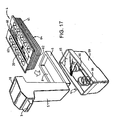
- Figure 17 Another embodiment of the invention is shown in Figure 17 , which is generally similar to the example shown in Figures 1 to 3 , with the modification that the container 4 does not contain an integrally moulded spring 17 in its base and instead the spring function is performed by an external loading box 59 which fits onto the underside of the frame 6.
- the container 4 is integrally moulded in a plastics material and has a generally rectangular lip 7 and wings 19, 20 that function as previously described, with concertina side walls 60, 61, 62, 63 that extend to a planar base 64.
- the container 4 is placed in the packaging device as previously described, within the frame 6, and the loading box 59 is fitted to its underside.
- the concertina side walls 60-63 do not exhibit any significant spring function on the notes stacked in the container 4.
- the loading box 59 contains a platen 65 which is urged by compression springs 66 against the base 64 of the container 4 whilst the banknotes are being stacked therein by the packaging device 1.
- a closure member 9 is then inserted through inlet 10 and heat sealed onto the container 4 as previously described.
- the sealed container is then removed from the frame 6 and the loading box 59 for transport to a remote location where it is opened under secure conditions and then disposed of, having performed its useful function and no longer being capable of receiving a stack of banknotes from the packaging device 1.
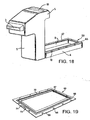
- FIG 18 illustrates another embodiment of packaging device, which is not part of the invention in which the heater 50 that seals the container 4 is mounted on the frame 6.
- the heater 50 comprises a printed circuit coil illustrated in more detail in Figure 19 and includes a generally rectangular printed circuit substrate 66 with a central opening 67 corresponding to the output port 8 shown in Figure 18 .
- the substrate 66 is provided with side edge detents 68 which receive hinges of the container, as will be described later.
- the underside 69 of the substrate 66 is glued or otherwise attached to the frame 6 shown in Figure 18 .
- the substrate 66 is provided with a printed circuit conductor 70 configured as a rectangular coil with terminals 71, 72 at opposite ends of its printed circuit track. In use, the terminals 71, 72 are connected to a D.C.
- the heating current source the supply of which is controlled by the circuitry 35 shown in Figure 10 .
- a 12V D.C. supply can be used, with the coil provided by the conductor 70 being rated at 4 watts.
- the printed circuit track 70 acts as a heating element to soften and partially melt the rectangular lip 7 and wings 19, 20 so that they become sealed to one another and also to the closure member 9.
- the heater 50 operates at temperature of around 200-220°C.
- the container 4 may for example be made of polypropylene with a melting point of around 260°C and the closure member 9 may be made of polyethylene with a melting point of 140-160°C. The heater 50 thus melts the closure member 9 onto a softened rails of the container 4 to seal the closure member 9 in place when cooled thereafter.
- the substrate 66 of heater 50 may be formed of conventional fibreglass or fibre reinforced paper and the printed circuit coil may be a Ti/Cu alloy formed by conventional printed circuit fabrication techniques.
- the outer surfaces of the substrate 66 may be coated with a conventional solder mask layer to protect the printed circuit coil conductor 70 and it has been found according to the invention that this solder mask layer acts as a release agent which causes the sealed container 4 and closure member 9 to release from the heater element 50 after heating, facilitating removal of the sealed container 4 from the packaging device.
- the solder mask may comprise an epoxy acrylic resin, for example OPSR 5600 G10 Serie supplied by Elga Europe Srl of Milan, Italy.
- the heater element may be cut e.g. by stamping from a sheet of printed circuit substrate 66 and the portion removed from the centre can be used as the substrate for circuitry 36 shown in Figure 8 , avoiding waste.
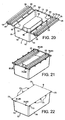
- FIG. 20-25 Another example of the container 4 is illustrated in Figures 20-25 .
- the container is shown with its wings 19, 20 open in Figure 20 , closed in Figure 21 and with the closure member 9 in place in Figure 22 .
- the wings 19, 20 are coupled to the lip 7 by individual, looped, spaced hinge regions 73 which hold the wings 19, 20 spaced from the lip 7 along the long sides 14, 16 of the container. Instead of using castellations as previously described, the wings 19, 20 are each provided with a pair of generally parallel elongate channel regions 74, 75, 76, 77. These channel regions act as stop against which the edges of the stacked banknotes abut when in the container.
- the main guide surface 23 that is used to guide banknotes comprises a continuous surface between the pairs of channel regions 74, 75; 76, 77, as shown in Figure 21 .
- Each of the wings 19, 20 is provided at opposite ends with closure lugs 78, 79, 80, 81, which are push-fitted into corresponding recesses 82, 83, 84 and 85 when the wings are closed, as shown in Figure 21 .
- twin channel configuration of the wings shown in Figures 20 and 21 provides a very effective stop against which the stacked banknotes abut when inserted into the container, with a result that no platen 21 as described with reference to Figure 24 , needs to be provided, and the base support region 18 operates effectively without such a platen to compress the stacked banknotes against the underside of the channel regions 74-77.
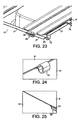
- Figure 23 is an enlarged view of a portion of Figure 21 , illustrating wing 20 when closed.
- the lip 7 has raised portions 7' between the hinge regions 73 and raised portions 7" on either side of the recess 82, so that the lip 7 in these regions is generally coextensive with the upper surface of the closed wing 20.
- operation of the heater 50 causes the closure member 9 to be sealed directly onto both the upper surface of the wing 20 and also onto the lip 7 and raised portions 7' and 7", thereby creating a tamper proof seal.
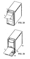
- FIG. 26 Another embodiment of the packaging device, which is not part of the invention is illustrated in Figures 26 to 29 , which can use the container 4 illustrated in Figures 22 and 25 .
- the device is for use in supermarkets and like sales outlets and can be placed under the counter near a till at a checkout location.
- the device consists of a generally rectangular main body 86 which contains a mechanism for loading the banknotes into the container 4 and sealing a closure member 9 onto the filled container 4.
- the housing 86 contains mechanisms and circuitry generally as described with reference to Figures 8-10 , but with different a configuration of paths for the banknotes 2 and the closure member 9 to follow to the container 4. Also the manner in which the container is docked and removed from the main body 86 is somewhat different from the previously described embodiment, as will now be discussed in more detail.
- the main body 86 includes a slot 3 to receive banknote 2 as shown in Figure 28 .
- a till operator inserts banknotes into slot 3 and they are validated and conveyed along a path within the main body 86 into the container 4 by means of a mechanism generally similar to that already described with reference to Figures 8 to 10 .
- the door 87 is opened to expose a slot 10 into which a closure member 9 for the container 4 can be inserted.
- a heater device as described with reference to Figures 8-10 then seals the closure member 9 onto the container 4 in the manner previously described.
- the container 4 can then be removed from the housing 86 by opening the tray 88 as illustrated in Figure 27 .
- the device shown in Figure 26 may include a printed circuit heater 50 as previously described, which may be mounted on the tray 88 or within the housing 86.
- a radio frequency identification (RFID) tag may be included on or in the container 4 or the closure member 9. This may be in the form of a printed coil or other techniques may be used as known in the art such as described in W09935610 . Reference is also directed to International Standard ISO 15693 for details of a specification of RFID tags that operate in the 13.56 MHz frequency band.
- the tag may contain a small amount of data so that if a person attempts to take the sealed container containing the banknotes from the premises, the data can be detected using r.f. detectors to set off an alarm.
Landscapes
- Engineering & Computer Science (AREA)
- Mechanical Engineering (AREA)
- General Physics & Mathematics (AREA)
- Physics & Mathematics (AREA)
- Ceramic Engineering (AREA)
- Packaging Of Special Articles (AREA)
- Packages (AREA)
- Packaging Of Annular Or Rod-Shaped Articles, Wearing Apparel, Cassettes, Or The Like (AREA)
- Sheets, Magazines, And Separation Thereof (AREA)
- Details Of Rigid Or Semi-Rigid Containers (AREA)
- Basic Packing Technique (AREA)
- Auxiliary Devices For And Details Of Packaging Control (AREA)
- Cash Registers Or Receiving Machines (AREA)
- Purses, Travelling Bags, Baskets, Or Suitcases (AREA)
Description
- This invention relates to a container for sheet objects that have an attributable monetary value, for example paper money such as banknotes or like promissory notes and a method of filling such a container.
- Hitherto, banknotes have been counted in note counting machines and wrapped in stacks with paper bands. Also, vacuum packing machines have been used to pack stacks of banknotes in airtight bags that are evacuated of air and sealed. Banknotes packaged in this way can be transported readily without the risk of the individual stacks being pilfered. However vacuum packing machines are expensive and normally used only for processing large volumes of banknotes.
- For smaller volume applications, for example in retail operations, devices such as our WACS 5 (World Acceptor Cassette System) note bill and bar coded ticket/coupon acceptor may be used, which has a cassette stacking system. The cassette comprises a metal box that receives validated bank notes or the like from a note acceptor. The cassette can store of the order of 500 street-grade banknotes. The cassette may be removed by an operator and taken to a secure location where it is unloaded, for onward transmission of the banknotes e.g. to a bank. A problem with the cassette system is that it can be opened during transport and runs the risk of pilfering. Furthermore, the cassette provides no ready indication that it has been opened and that pilfering may have occurred.
- Reference is directed to
EP-A-125842 EP-A-0852279 which discloses disposable packaging for banknotes. Furthermore, reference is directed toDE 3931176 which discloses one-time use security containers for banknotes that comprise a container with a sealed rid. - According to the invention there is provided a container for packaging sheet objects with an attributable monetary value, comprising an opening to receive the sheet objects, a base, sidewalls extending towards the opening from the base, and members hingedly coupled to the side walls on opposite sides of the opening, the container being configured to receive a closure member sealed thereto over the opening so that the container cannot be reused for stacking sheet objects once opened characterised in that the members comprise support rails that are hinged for movement from a storage position exteriorly of the opening, to an operative position within the opening for guiding the sheet objects to overlie the opening and past which the sheet objects resiliently deform when placed in the container in a stacked configuration, the support rails each including a main guide surface to guide a side edge region the sheet members to be stacked within the container, stop regions for providing a stop against which a stack of sheet objects abuts when in the container, and a coupling portion coupling said main guide surface hingedly to a said side wall.
- Thus by means of the invention, sheet objects such as banknotes can be stacked in the container which can then be provided with a sealed closure member so that once opened, the container cannot be reused for packing sheet objects. The container thus provides a clear indication as to whether the contents have been tampered with. Thus, the container may be disposable and need not be returned for re-use as with a conventional cassette, which is a relatively expensive item.
- In order that the invention may be more fully understood an embodiment thereof will now be described by way of example with reference to the accompanying drawings in which:
-
Figure 1 is a schematic perspective view of a packaging device and associated single use container in accordance with the invention, in a closed configuration with the container fitted ready for use; -
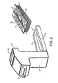
Figure 2 corresponds to the view ofFigure 1 but with the device open to receive the container, prior to use; -
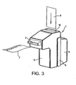
Figure 3 corresponds toFigure 1 and shows the insertion of a closure member that is sealed to the container; -
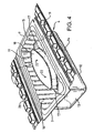
Figure 4 is a schematic perspective view of first example of a container; -
Figure 5 is partially broken away perspective view of the container with one of its support rails in an open position; -
Figure 6 corresponds toFigure 5 but with the support rail in a closed position; -
Figure 7a is a partial sectional view of one side of the container when empty taken along the line A-A' ofFigure 5 with the support rail in the open position; -
Figure 7b is a partial sectional view of the other side of the container when full of banknotes, taken along the line A-A' ofFigure 5 with the support rail in the open position; -
Figure 8 is a longitudinal, sectional view of the packaging device with the container empty; -
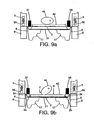
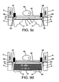
Figure 9a - 9d are views of the packaging device in transverse section illustrating operation of the drive mechanism to fill the container; -
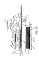
Figure 10 corresponds toFigure 8 but with the container full; -
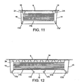
Figure 11 is a transverse section of another embodiment of the container; -
Figure 12 is a longitudinal section of the container shown inFigure 11 ; -
Figure 13 is a perspective view of a support rail of the container ofFigures 11 and 12 ; -
Figure 14 is a top plan view of the container shown inFigures 11 and 12 ; -
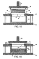
Figure 15 is a sectional view of a container emptying device for emptying the contents of the container, ready for use; -
Figure 16 is a sectional view of the emptying device after use; -
Figure 17 is a schematic perspective view of another embodiment of the invention in which the container does not have an integral spring; -
Figure 18 is a schematic perspective view of another embodiment of packaging device according to the invention, with a printed circuit heater; -
Figure 19 is an enlarged view of the heater shown inFigure 18 ; -
Figure 20 is a schematic perspective view of another example of a container with its wings open; -
Figure 21 corresponds toFigure 20 with the wings closed; -
Figure 22 illustrates the container ofFigure 20 with a closure member sealed thereto; -
Figure 23 is an enlarged view corresponding toFigure 21 ; -
Figure 24 illustrates a hinge of the container ofFigure 20 , with the closure member sealed thereto; -
Figure 25 illustrates the configuration of one of the closure lags when the closure member is sealed onto the container; -
Figure 26 is a schematic perspective view of another embodiment of the packaging device which is suited to use in supermarkets and like sales outlets; -
Figure 27 illustrates the insertion or replacement of a container to receive banknotes into the device ofFigure 26 ; -
Figure 28 illustrates the insertion of a banknote into the device shown inFigure 26 ; and -
Figure 29 illustrates the insertion of the closure member into the device shown inFigure 26 , for being sealed onto the container. - The example of the invention illustrated in the drawings is for packaging banknotes and as used herein, the term "banknote" means a promissory note especially from a central bank or other governmental organisation payable to the bearer on demand for use as money, also known as "paper money" and in the USA as "currency" or a "bill".
- Referring to
Figure 1 , apackaging device 1, which is not part of the invention, is configured to receiveindividual banknotes 2 through aninput slot 3 and stack them in aremovable container 4. Thepacking device 1 may be mounted at a point of sale in a retail outlet, for example at a checkout in a supermarket so that banknotes can be packaged incontainer 4 and then transported securely to a remote location such as a cashier's office. - The
packaging device 1 comprises amain body 5 and aframe 6 mounted on the main body to receive thecontainer 4. Theframe 6 is hinged on themain body 5 in this example, so that it can be moved between a closed position shown inFigure 1 to an open position shown inFigure 2 , to act as a docking mechanism that allows thecontainer 4 to be inserted and removed between the frame and the main body. Thecontainer 4 is a generally rectangular in configuration to be described in more detail hereinafter, with aperipheral lip 7. Theframe 6 defines anoutput port 8 through which thecontainer 4 protrudes as shown inFigure 1 , with itslip 7 sandwiched between themain body 5 and theframe 6. - Referring to
Figure 3 , when the container becomes full ofbanknotes 2, a closure member in the form of asealing card 9 is inserted through asecond input port 10 in themain body 5, to be heat sealed onto thecontainer 4. Thus, when theframe 6 is opened as shown inFigure 2 , a sealed container is provided containing the banknotes for transport to the cashier's office. - Referring to
Figure 4 , thecontainer 4 is manufactured as a one piece moulding of a thermoplastics material and comprises a generallyrectangular opening 11 bounded by thelip 7, abase 12, andsidewalls lip 7. Thesidewalls - The dimensions of the
opening 11 are chosen to allow the insertion of a particular denomination of banknote, with thesidewalls - The
base 12 is moulded to includecorrugations 17 that are disposed between a central,base support region 18 and the sidewalls 13-16. In this example, thebase support region 18 is elliptical but as will be evident hereinafter, other shapes can be used. Thecorrugations 17 act as a compression spring to urge thebase support region 18 towards the opening 11 as successive banknotes are inserted into the container. - Support rails in the form of elongate,
castellated wings lip 7 along the long sides of thecontainer 4. Thewings Figure 4 and as a result, a plurality ofcontainers 4 can be stacked one within the other, enabling a supply of containers to be easily delivered and stored adjacent the packaging device at the point of sale, ready for use. - In order to prepare a
container 4 for use in thepackaging device 1, a relatively rigid rectangular platen 21 (not shown inFig.4 but illustrated inFig. 8 ) is placed on thebase support region 18. Theplaten 21 may comprise a moulded plastics member that couples to thebase support region 18 by cooperating pegs andreceptacles 22, or theplaten 21 may simply be a rectangular piece of cardboard or similar material that rests on thebase support region 18. Theplaten 21 extends to the sidewalls of thecontainer 4 to support the banknotes. Thereafter, thewings Figure 4 , in the direction of arrows X. As explained in more detail hereinafter, thewings container 4 through theopening 11. - The
wing 19 is shown in its initial, outwardly extending position inFigure 5 and its inwardly folded position inFigure 6 . Thewing 19 comprises amain guide surface 23 formed with a series of indentations that give rise tocastellations 24, anouter lip 25, ahinge line 26 and acoupling surface 27 that connects themain guide surface 23 to thehinge line 26. - When the
wings container 4 is inserted into thepackaging device 1, thecoupling surface 27 is welded to thelip 7 by thepackaging device 1 in theregion 28 shown inFigure 7b after having been filled with banknotes. InFigure 7a , thewing 20 is shown in its initial, outwardly extending position, with nobanknotes 2 in the container and with the spring corrugations 17 in their initial, uncompressed state. It will be understood that the wing 19 (not shown inFigure 7a ) will be in a similar configuration towing 20.Figure 7b illustrates the configuration when thecontainer 4 has been filled with astack 29 ofbanknotes 2. In this situation, theplaten 21 has been compressed downwardly to accommodate thestack 29 of banknotes thereby compressing thecorrugations 17 in the base of thecontainer 4. Thewing 19 has been hinged inwardly in the direction of arrow X and welded inregion 28 againstlip 7 so that thecastellations 24 provide a downwardly depending stop region to hold thestack 29 of banknotes within the container. It will be understood that the wing 20 (not shown inFigure 7b ) will be similarly welded againstlip 7. - The way in which the
packaging device 1 fills the container with banknotes will now be described in more detail. Referring toFigure 8 , a cross sectional view of the packaging device is shown, with thecontainer 4 received inframe 6, empty and ready to receive banknotes. Thewings container 4 have been folded inwardly into the position shown schematically inFigure 2 , and are clamped in this position between themain body 5 and theframe 6. - The
main body 5 includes aninput path 30 that extends from thefirst input port 3 through a banknote sensing station S, to theoutput port 8 inframe 6. When thebanknote 2 is inserted into thefirst input port 3 it is detected by anoptical sensor 31 that activates driven roller pairs 32, 33 to drive thebanknote 2 past avalidation sensor arrangement 34 at the sensing station S, coupled tovalidation circuitry 35 mounted on a printedcircuit board 36. Thevalidation sensor arrangement 34 and associatedcircuitry 35 may correspond to our Ardac technology described inUnited States Patent No. 4,348,656 . Thevalidation sensor arrangement 34 andcircuitry 35 can sense the acceptability, number and denomination of banknotes that enter theinput port 3. In the event that thebanknote 2 is determined to be a true banknote as opposed to a fraud by thesensor arrangement 34 and associatedcircuitry 35, the drive roller pairs 32, 33 transport thebanknote 2 towards theoutput port 8. Otherwise, the roller pairs 32, 33 are driven in reverse so that thebanknote 2 is ejected from theinput port 3. - Assuming that the
banknote 2 is acceptable, it is passed by therollers drive belts Figure 9a , which engage longitudinal side edges of the banknote and move it into alignment with theoutput port 8. Considering thebelt 38 in more detail, it extends betweenpulleys motor 41 in the direction of arrows Y such that the banknote is drawn by thebelts output port 8. - The banknote drive mechanism also includes a
plunger 42 in the form of a rigid plate that is mounted for movement downwardly between thebelts banknote 2 into thecontainer 4. To this end, amotor 43 driveselliptical cams drive train cams Figure 9b ) to drive theplunger 42 together with thebanknote 2, into thecontainer 4 through theopening 11, in a direction perpendicular to the plane of the banknote when it arrives at theopening 11 along theinput path 30. - This process is shown in more detail in
Figures 9a - 9d . Referring toFigure 9a , thebanknote 2 is driven bybelts wings banknote 2. When the banknote becomes aligned with theoutput port 8 inframe 6, themotor 43 is operated to rotate thecams Figure 9b . As a result, theplunger 42 is moved downwardly in the direction of arrow D so that thebelts wings Side edges plunger 42 moves downwardly past thecastellations 24, and theentire banknote 2 is moved into thecontainer 4. As thecams plunger 42 and thebanknote 2 are driven downwardly against theplaten 21, such as to compress thespring 17, thereby allowing theside edges castellations 24. - The
cams Figure 9c . Thus, thebanknote 2 is inserted into thecontainer 4 and it held therein by the compressive force ofspring 17, against thecastellations 24, which act as stop regions to hold the banknote in thecontainer 4. - Successive banknotes are inserted into the container to form the
banknote stack 29 shown inFigure 9d , with the uppermost banknote being held under thecastellations 24. -
Figure 10 shows thestack 29 in thecontainer 4, with theplaten 21 having been moved downwardly. The compressive force ofspring 17 urges thestack 29 upwardly against thecastellations 24 to hold the banknotes securely within the container. - When the
container 4 is full, and operator inserts theclosure member 9 through thesecond input port 10. Theclosure member 9 comprises an optically transparent or translucent sheet of plastics material. Theclosure member 9 is detected by anoptical sensor 48 and moves along a closuremember inlet path 49 that extends into theinput path 30 for banknotes, so as to become engaged with and driven by thedrive belts output port 8, in a similar manner to the banknotes during the previously described banknote stacking process. Theclosure member 9 thus becomes positioned over theinlet 11 of thecontainer 4 with the side edges of theclosure member 9 extending over the main guide surfaces 23 of thewings lip 7 on theshorter sides Figure 9d , themain body 6 of the packaging device includeselectrical heaters 50. In use, when theclosure member 9 becomes aligned with theopening 11 of the container, theheaters 50 are switched on so as to heat seal theclosure member 9 onto thewings rim 7 of the container i.e. to produce theweld 28 shown inFigure 7 . - As shown in
Figure 10 , themain body 5 includes aprint head 51 operable to print data on the underside of theclosure member 9 so that when sealed onto thecontainer 4, the printed data is within the container and cannot be altered except by opening it. Theprint head 51 is operable to print in a mirror image so that the data can be read normally through thetransparent closure member 9 from outside thecontainer 4. Thecircuitry 35 is operable to collate data concerning the number and denomination of banknotes that have been stacked instack 29 in thecontainer 4 and this data can be printed on the underside of theclosure member 9 using theprint head 51. - After the sealing of the
closure member 9 on thecontainer 4, theframe 6 can be opened as shown inFigure 2 and the sealed container can be removed and transported to another location, for example to the cashier's office. The resulting packaged banknotes cannot readily be tampered with during transport because theclosure member 9 is heat sealed to thecontainer 4 protecting its contents. If the sealedcontainer 4 is opened, this is readily apparent and the container cannot be subsequently reused in the packaging device. Thus, the risk of fraud is materially reduced. Also, the printing of data corresponding to the contents of the container on the inside of the closure member means that the printed indicia cannot readily abraded or otherwise altered. -
Figures 11 to 14 illustrate a modified version of thecontainer 4, which does not have aseparate platen 21. In the container ofFigure 4 , theplaten 21 provides a rigid support for the relatively flexible banknotes as they become stacked in the container so that side edges of the banknotes can be reliably abutted against the undersides of thecastellations 24. Without the relativelyrigid platen 21, the relatively flexible banknotes may tend to curve around thebase support region 18 and thespring region 17 in a domed configuration such that the banknotes are not reliably held on the undersides of thecastellations 24. In the container shown inFigure 11 to 14 , the platen is formed integrally in twoparts 21 a, 21b with thebase 12 of thecontainer 4. As shown inFigure 11 , theplaten 21 a extends substantially the entire width of thecontainer 4 so that thestack 29 of banknotes within the container is supported across the entire width of the banknotes by the relativelyrigid platen 21a. Thecorrugated regions 17a around theplaten 21a give rise to an integral compression spring with the main compressive force being given byregions 17a' shown inFigure 12 and thelongitudinal portions 17a" providing less of a spring effect. The platen region 21 b is configured in a similar manner with surroundingintegral springs 17b. -
Figure 14 illustrates thecontainer 4 in plan view with theclosure member 9 heat sealed onto thewings flange 7. Printeddata 52 on the underside of theclosure member 9 has been printed thereon by means of theprint head 51 shown inFigure 8 . - The
closure member 9 includes a line ofweakness 53 to facilitate opening thecontainer 4 when filled with banknotes. Theclosure member 9 can be manually depressed downwardly in the centre thereof so as to cause theclosure member 9 to tear along the line ofweakness 53. The contents can then be removed. - It will be understood that according to the invention, the
container 4 cannot be reused for packaging banknotes in thepackaging device 1 once the container has been opened, providing a clear visual indication of whether the packaging device has been tampered with after closure. Moreover, when opened, the data printed on theclosure member 9 can be used to verify the contents of thecontainer 4. - The process of opening the container can be automated by means of a device, which is not part of the invention, illustrated in
Figures 15 and 16 . The device empties the contents of thecontainer 4 into atray 54 received on asupport 55 beneath aplatform 56 that includes arelease aperture 57 with dimensions corresponding to theopening 11 of the container. In use, thecontainer 4 is placed upside down with opening 11 coextensive with therelease aperture 57. Aram 58 is operated downwardly in the direction of arrow R with sufficient force to collapse thesidewalls container 4 and press thestack 29 of banknotes against theclosure member 9, causing it to burst along the line ofweakness 53. Continued movement of theram 58 in the direction of arrow R causes the banknotes to deform past thecastellations 24 and drop into thetray 54 as shown inFigure 16 , together with the printedclosure member 9. The tray can then be removed from the device. Theram 58 is released and the remains of thecontainer 4 are discarded. - Another embodiment of the invention is shown in
Figure 17 , which is generally similar to the example shown inFigures 1 to 3 , with the modification that thecontainer 4 does not contain an integrally mouldedspring 17 in its base and instead the spring function is performed by anexternal loading box 59 which fits onto the underside of theframe 6. - The
container 4 is integrally moulded in a plastics material and has a generallyrectangular lip 7 andwings concertina side walls planar base 64. Thecontainer 4 is placed in the packaging device as previously described, within theframe 6, and theloading box 59 is fitted to its underside. The concertina side walls 60-63 do not exhibit any significant spring function on the notes stacked in thecontainer 4. Instead, theloading box 59 contains aplaten 65 which is urged by compression springs 66 against thebase 64 of thecontainer 4 whilst the banknotes are being stacked therein by thepackaging device 1. Aclosure member 9 is then inserted throughinlet 10 and heat sealed onto thecontainer 4 as previously described. The sealed container is then removed from theframe 6 and theloading box 59 for transport to a remote location where it is opened under secure conditions and then disposed of, having performed its useful function and no longer being capable of receiving a stack of banknotes from thepackaging device 1. -
Figure 18 illustrates another embodiment of packaging device, which is not part of the invention in which theheater 50 that seals thecontainer 4 is mounted on theframe 6. Theheater 50 comprises a printed circuit coil illustrated in more detail inFigure 19 and includes a generally rectangular printedcircuit substrate 66 with acentral opening 67 corresponding to theoutput port 8 shown inFigure 18 . Thesubstrate 66 is provided withside edge detents 68 which receive hinges of the container, as will be described later. Theunderside 69 of thesubstrate 66 is glued or otherwise attached to theframe 6 shown inFigure 18 . Thesubstrate 66 is provided with a printedcircuit conductor 70 configured as a rectangular coil withterminals terminals circuitry 35 shown inFigure 10 . For example, a 12V D.C. supply can be used, with the coil provided by theconductor 70 being rated at 4 watts. When energised, the printedcircuit track 70 acts as a heating element to soften and partially melt therectangular lip 7 andwings closure member 9. In one example, theheater 50 operates at temperature of around 200-220°C. Thecontainer 4 may for example be made of polypropylene with a melting point of around 260°C and theclosure member 9 may be made of polyethylene with a melting point of 140-160°C. Theheater 50 thus melts theclosure member 9 onto a softened rails of thecontainer 4 to seal theclosure member 9 in place when cooled thereafter. - The
substrate 66 ofheater 50 may be formed of conventional fibreglass or fibre reinforced paper and the printed circuit coil may be a Ti/Cu alloy formed by conventional printed circuit fabrication techniques. The outer surfaces of thesubstrate 66 may be coated with a conventional solder mask layer to protect the printedcircuit coil conductor 70 and it has been found according to the invention that this solder mask layer acts as a release agent which causes the sealedcontainer 4 andclosure member 9 to release from theheater element 50 after heating, facilitating removal of the sealedcontainer 4 from the packaging device. The solder mask may comprise an epoxy acrylic resin, for example OPSR 5600 G10 Serie supplied by Elga Europe Srl of Milan, Italy. The heater element may be cut e.g. by stamping from a sheet of printedcircuit substrate 66 and the portion removed from the centre can be used as the substrate forcircuitry 36 shown inFigure 8 , avoiding waste. - Many modifications to this arrangement are possible. For example, the
heater 50 may be mounted on themain body 5 instead of on theframe 6 or such heaters may be provided both on thebody member 5 andframe 6. - Another example of the
container 4 is illustrated inFigures 20-25 . The container is shown with itswings Figure 20 , closed inFigure 21 and with theclosure member 9 in place inFigure 22 . - Referring to
Figure 20 , thecontainer 4 is manufactured as a stackable, one piece moulding of thermoplastics material and comprises a generallyrectangular opening 11 bounded bylip 7,base 12, sidewalls 13, 14, 15 and 16 that extend from the base to theopening 11 and thelip 7.Elongate wings lip 7 along the long sides of the container. Thebase 12 is moulded to includecorrugations 17 that are disposed between a generally rectangular central,base support region 18 and thesidewalls 13 to 16. As previously described, thecorrugations 17 act as a compression spring to urge thebase support region 18 towards the opening 11 as successive banknotes are inserted into the container. - The
wings lip 7 by individual, looped, spacedhinge regions 73 which hold thewings lip 7 along thelong sides wings elongate channel regions - The
main guide surface 23 that is used to guide banknotes comprises a continuous surface between the pairs ofchannel regions 74, 75; 76, 77, as shown inFigure 21 . - Each of the
wings recesses Figure 21 . - It has been found that the twin channel configuration of the wings shown in
Figures 20 and 21 provides a very effective stop against which the stacked banknotes abut when inserted into the container, with a result that noplaten 21 as described with reference toFigure 24 , needs to be provided, and thebase support region 18 operates effectively without such a platen to compress the stacked banknotes against the underside of the channel regions 74-77. -
Figure 23 is an enlarged view of a portion ofFigure 21 , illustratingwing 20 when closed. Thelip 7 has raised portions 7' between thehinge regions 73 and raisedportions 7" on either side of therecess 82, so that thelip 7 in these regions is generally coextensive with the upper surface of theclosed wing 20. In this way, when theclosure member 9 overlies eachhinge region 73 as illustrated inFigure 24 and also theclosure lug 78 inserted into therecess 82, operation of theheater 50 causes theclosure member 9 to be sealed directly onto both the upper surface of thewing 20 and also onto thelip 7 and raisedportions 7' and 7", thereby creating a tamper proof seal. - Referring again to
Figures 18 and 19 , it will be seen that therecesses 68 in theheater element 50 are configured to receive thehinge regions 73 and the recesses 82-85, to allow the container to sit flush on theheater 50. - Another embodiment of the packaging device, which is not part of the invention is illustrated in
Figures 26 to 29 , which can use thecontainer 4 illustrated inFigures 22 and25 . Referring toFigure 26 , the device is for use in supermarkets and like sales outlets and can be placed under the counter near a till at a checkout location. The device consists of a generally rectangularmain body 86 which contains a mechanism for loading the banknotes into thecontainer 4 and sealing aclosure member 9 onto the filledcontainer 4. To this end, thehousing 86 contains mechanisms and circuitry generally as described with reference toFigures 8-10 , but with different a configuration of paths for thebanknotes 2 and theclosure member 9 to follow to thecontainer 4. Also the manner in which the container is docked and removed from themain body 86 is somewhat different from the previously described embodiment, as will now be discussed in more detail. - Referring to
Figure 27 , a hingeddoor 87 can be opened downwardly to allow aslidable tray 88 to extend outwardly of thehousing 86. Thetray 88 and acts as a frame into whichcontainer 4 can be inserted, with itswings rectangular opening 89 in thetray 88 receives thecontainer 4 in a similar manner to theframe 6 shown inFigure 2 . Thecontainer 4 is shown partially inserted in theopening 89 inFigure 27 . When fully inserted, the tray can be pushed inwardly ofbody 86 and thedoor 87 closed, in order to dock thecontainer 4 in themain body 86, to be filled with banknotes. - The
main body 86 includes aslot 3 to receivebanknote 2 as shown inFigure 28 . In use, a till operator inserts banknotes intoslot 3 and they are validated and conveyed along a path within themain body 86 into thecontainer 4 by means of a mechanism generally similar to that already described with reference toFigures 8 to 10 . - When the
container 4 becomes full of banknotes, thedoor 87 is opened to expose aslot 10 into which aclosure member 9 for thecontainer 4 can be inserted. A heater device as described with reference toFigures 8-10 then seals theclosure member 9 onto thecontainer 4 in the manner previously described. Thecontainer 4 can then be removed from thehousing 86 by opening thetray 88 as illustrated inFigure 27 . The device shown inFigure 26 may include a printedcircuit heater 50 as previously described, which may be mounted on thetray 88 or within thehousing 86. - Many modifications and variations of the described embodiments fall within the scope of the invention. For example, whilst the packaging of banknotes has been described, other sheet objects with an attributable monetary value can be packaged in accordance with the invention, such as tokens or coupons, which may be bar-coded, and vouchers providing a discount or other promotional scheme.
- Also, instead of or in addition to the printing carried out by the
print head 51, a radio frequency identification (RFID) tag may be included on or in thecontainer 4 or theclosure member 9. This may be in the form of a printed coil or other techniques may be used as known in the art such as described inW09935610
Claims (25)
- A container (4) for packaging sheet objects (2) with an attributable monetary value, comprising an opening (11) to receive the sheet objects, a base (12), sidewalls (13-16) extending towards the opening from the base, and members (19, 20) hingedly coupled to the side walls on opposite sides of the opening, the container being configured to receive a closure member (9) sealed thereto over the opening so that the container cannot be reused for stacking sheet objects once opened characterised in that the members (19, 20) comprise support rails that are hinged for movement from a storage position exteriorly of the opening, to an operative position within the opening for guiding the sheet objects to overlie the opening and past which the sheet objects resiliently deform when placed in the container in a stacked configuration, the support rails each including a main guide surface (23) to guide a side edge region the sheet members to be stacked within the container, stop regions (24; 74 -77) for providing a stop against which a stack of sheet objects abuts when in the container, and a coupling portion (27) coupling said main guide surface hingedly to a said side wall.
- A container according to claim 1 wherein the base includes a spring to urge the stacked configuration of sheet objects against the support rails.
- A container according to claim 2 wherein the spring comprises corrugations (17) in the base.
- A container according to any preceding claim wherein the support rails comprise wings (19,20) coupled by integral hinges (26; 73) to a lip (7) around the opening (11).
- A container according to claim 4 wherein the hinges comprise spaced hinge regions (73) that hold the wings spaced from the lip.
- A container according to claim 4 wherein the lip includes raised portions (7', 7") between the hinge regions (73) that are coplanar with the upper side of the wings when in said operative position.
- A container according to claim 1 wherein the stop regions comprise castellations (24).
- A container according to claim 1 wherein the stop regions comprise channels (74-77) in the support rails.
- A container according to any one of the preceding claims including a spring loaded platen (18, 21) on the base, the platen being configured to receive the stack of sheet members and urge the stack against the rails.
- A container according to any one of the preceding claims , which is integrally moulded.
- A container according to claim 10, integrally moulded in a plastics material.
- A container according to claim 9 wherein the platen comprises a discrete element (21) on the base.
- A container according to claim 9 wherein the platen (18) is integral with the base.
- A container according to claim 9 wherein the base includes a plurality of platen portions (21a,21b) each resiliently biased towards the support rails.
- A container according to any one of the preceding claims wherein a plurality thereof can stack one within the other.
- A container according to any one of the preceding claims and including the closure member (9).
- A container according to claim 16 and including the closure member sealed to the opening.
- A container according to claim 17 wherein the closure member has been heat-sealed thereon.
- A container according to 16, 17 or 18 wherein the closure member includes a line of weakness (53) along which it can subsequently tear to facilitate removal of the sheet objects.
- A container according to any one of the preceding claims containing a stack of said sheet objects (2).
- A container according to claim 18 wherein the sheet objects comprise banknotes or like promissory notes of attributable monetary value.
- A container according to claim 20 or 21 wherein data relating to said stack of sheet members (52) is printed on the closure member.
- A container according to claim 22 wherein the data is printed on the inside of the closure member.
- A container according to any one of the preceding claims with a RFID device.
- A method of filling a container according to any preceding claim with sheet objects, comprising moving the support rails (19, 20) from their storage position to their operative position, and for a plurality of sheet objects, moving the sheet object along the rails so that its major face overlies the opening (11), and driving the sheet object transversely of its major face into the opening such that its side edges deform past the rails, so as to build a stack of the sheet objects in the container pressing against the rails, and sealing a closure member to the container over the opening.
Applications Claiming Priority (2)
| Application Number | Priority Date | Filing Date | Title |
|---|---|---|---|
| GBGB0327522.9A GB0327522D0 (en) | 2003-11-26 | 2003-11-26 | Packaging device and container for sheet objects |
| EP04798695A EP1687204B1 (en) | 2003-11-26 | 2004-11-26 | Packaging device and container for sheet objects |
Related Parent Applications (2)
| Application Number | Title | Priority Date | Filing Date |
|---|---|---|---|
| EP04798695A Division EP1687204B1 (en) | 2003-11-26 | 2004-11-26 | Packaging device and container for sheet objects |
| EP04798695.5 Division | 2004-11-26 |
Publications (3)
| Publication Number | Publication Date |
|---|---|
| EP1755089A2 EP1755089A2 (en) | 2007-02-21 |
| EP1755089A3 EP1755089A3 (en) | 2007-03-07 |
| EP1755089B1 true EP1755089B1 (en) | 2011-03-30 |
Family
ID=29797869
Family Applications (3)
| Application Number | Title | Priority Date | Filing Date |
|---|---|---|---|
| EP04798695A Expired - Lifetime EP1687204B1 (en) | 2003-11-26 | 2004-11-26 | Packaging device and container for sheet objects |
| EP04798694A Withdrawn EP1687780A1 (en) | 2003-11-26 | 2004-11-26 | Packaging device and container for sheet objects |
| EP06125453A Expired - Lifetime EP1755089B1 (en) | 2003-11-26 | 2004-11-26 | Packaging device and container for sheet objects |
Family Applications Before (2)
| Application Number | Title | Priority Date | Filing Date |
|---|---|---|---|
| EP04798695A Expired - Lifetime EP1687204B1 (en) | 2003-11-26 | 2004-11-26 | Packaging device and container for sheet objects |
| EP04798694A Withdrawn EP1687780A1 (en) | 2003-11-26 | 2004-11-26 | Packaging device and container for sheet objects |
Country Status (10)
| Country | Link |
|---|---|
| US (2) | US7559183B2 (en) |
| EP (3) | EP1687204B1 (en) |
| JP (2) | JP2007512192A (en) |
| CN (2) | CN100534865C (en) |
| AU (2) | AU2004295160B2 (en) |
| DE (1) | DE602004032061D1 (en) |
| GB (1) | GB0327522D0 (en) |
| RU (2) | RU2375752C2 (en) |
| WO (2) | WO2005055159A1 (en) |
| ZA (2) | ZA200603923B (en) |
Families Citing this family (60)
| Publication number | Priority date | Publication date | Assignee | Title |
|---|---|---|---|---|
| US7603518B2 (en) | 2005-12-19 | 2009-10-13 | Commvault Systems, Inc. | System and method for improved media identification in a storage device |
| US8346733B2 (en) | 2006-12-22 | 2013-01-01 | Commvault Systems, Inc. | Systems and methods of media management, such as management of media to and from a media storage library |
| EP1446773A1 (en) * | 2001-11-23 | 2004-08-18 | De La Rue International Limited | Verification method and apparatus |
| US7584227B2 (en) * | 2005-12-19 | 2009-09-01 | Commvault Systems, Inc. | System and method for containerized data storage and tracking |
| WO2004090740A1 (en) | 2003-04-03 | 2004-10-21 | Commvault Systems, Inc. | System and method for dynamically sharing media in a computer network |
| WO2004090789A2 (en) | 2003-04-03 | 2004-10-21 | Commvault Systems, Inc. | System and method for extended media retention |
| GB0327522D0 (en) * | 2003-11-26 | 2003-12-31 | Money Controls Ltd | Packaging device and container for sheet objects |
| US20060224846A1 (en) | 2004-11-05 | 2006-10-05 | Amarendran Arun P | System and method to support single instance storage operations |
| GB0426137D0 (en) * | 2004-11-26 | 2004-12-29 | Money Controls Ltd | A device for processing sheet objects such as banknotes |
| EP1924689B1 (en) * | 2005-09-01 | 2014-08-13 | Novo Nordisk Health Care AG | Hydrophobic interaction chromatography purification of factor vii polypeptides |
| AU2006340804B2 (en) * | 2005-12-27 | 2012-01-12 | Mei, Inc. | Secure bag assembly for a lockable removable cassette |
| US8851373B2 (en) | 2006-06-14 | 2014-10-07 | Mei, Inc. | Tracking information in a note handling facility |
| FR2903210B1 (en) * | 2006-07-03 | 2008-11-14 | Tessi Cheque Soc Par Actions S | CHECK DELIVERY DEVICE |
| US7539783B2 (en) | 2006-09-22 | 2009-05-26 | Commvault Systems, Inc. | Systems and methods of media management, such as management of media to and from a media storage library, including removable media |
| CH705647B1 (en) * | 2006-10-13 | 2013-04-30 | Ferag Ag | RFID printing product identification. |
| US7831566B2 (en) | 2006-12-22 | 2010-11-09 | Commvault Systems, Inc. | Systems and methods of hierarchical storage management, such as global management of storage operations |
| AU2008258342A1 (en) * | 2007-06-04 | 2008-12-11 | Ferag Ag | Method for interaction between a user and a receiver of a printed product |
| US8706976B2 (en) | 2007-08-30 | 2014-04-22 | Commvault Systems, Inc. | Parallel access virtual tape library and drives |
| JP5188167B2 (en) * | 2007-12-20 | 2013-04-24 | 株式会社ユニバーサルエンターテインメント | Paper sheet processing equipment |
| DE102008023900A1 (en) | 2008-05-16 | 2009-11-19 | Wincor Nixdorf International Gmbh | Device for stacking banknotes, in particular banknotes |
| US8577802B1 (en) | 2008-06-16 | 2013-11-05 | Bank Of America Corporation | On-demand cash transport |
| US8094021B2 (en) * | 2008-06-16 | 2012-01-10 | Bank Of America Corporation | Monetary package security during transport through cash supply chain |
| US9024722B2 (en) * | 2008-06-16 | 2015-05-05 | Bank Of America Corporation | Remote identification equipped self-service monetary item handling device |
| GB0814282D0 (en) * | 2008-08-05 | 2008-10-29 | Money Controls Ltd | Security Device |
| US20100070466A1 (en) | 2008-09-15 | 2010-03-18 | Anand Prahlad | Data transfer techniques within data storage devices, such as network attached storage performing data migration |
| US8056305B1 (en) * | 2008-09-30 | 2011-11-15 | Bank Of America Corporation | Automatic strapping and bagging of funds |
| US8210429B1 (en) | 2008-10-31 | 2012-07-03 | Bank Of America Corporation | On demand transportation for cash handling device |
| DE102009015047A1 (en) * | 2009-03-26 | 2010-09-30 | Wincor Nixdorf International Gmbh | Device for filling a thin-walled transport container with notes of value |
| DE102009017410A1 (en) * | 2009-04-14 | 2010-10-21 | Giesecke & Devrient Gmbh | One-sided open disposable package for bank note in e.g. automated teller machine, has two sliding elements projected into input opening from opposite sides and comprising sliding surfaces that are bent inside package |
| DE102009053155A1 (en) * | 2009-11-06 | 2011-05-12 | Giesecke & Devrient Gmbh | Device for depositing sheet material in a disposable container |
| US9244779B2 (en) | 2010-09-30 | 2016-01-26 | Commvault Systems, Inc. | Data recovery operations, such as recovery from modified network data management protocol data |
| CN102566514A (en) * | 2010-11-25 | 2012-07-11 | 顾栽延 | Currency circulation safety management system based on Internet of Things |
| JP5595955B2 (en) * | 2011-03-18 | 2014-09-24 | 株式会社東芝 | Paper sheet processing equipment |
| US20120251248A1 (en) * | 2011-03-31 | 2012-10-04 | Tagashira Kenichi | Money handling system and money handling method |
| JP5815301B2 (en) * | 2011-06-24 | 2015-11-17 | グローリー株式会社 | Cash processing system, cash processing method, management department and cash accounting apparatus |
| US20130066799A1 (en) * | 2011-09-13 | 2013-03-14 | Burroughs Payment Systems, Inc. | Transporting Currency |
| US9529871B2 (en) | 2012-03-30 | 2016-12-27 | Commvault Systems, Inc. | Information management of mobile device data |
| EP2648165A1 (en) * | 2012-04-02 | 2013-10-09 | Peter Villiger | Device for holding bank notes, security system with such a device and method |
| WO2013183167A1 (en) * | 2012-06-08 | 2013-12-12 | グローリー株式会社 | Large-bundle creation system and large-bundle creation method |
| US9290983B2 (en) | 2012-12-17 | 2016-03-22 | Crane Payment Innovations, Inc. | Tamper evident storage device for items of value |
| US9069799B2 (en) | 2012-12-27 | 2015-06-30 | Commvault Systems, Inc. | Restoration of centralized data storage manager, such as data storage manager in a hierarchical data storage system |
| CN104063945B (en) * | 2013-03-18 | 2019-05-28 | 光荣株式会社 | banknote handling device |
| JP2015056010A (en) * | 2013-09-11 | 2015-03-23 | グローリー株式会社 | Bill management system and bill management method |
| US9058710B2 (en) * | 2013-10-04 | 2015-06-16 | Giesecke & Devrient America, Inc. | Systems, methods, and computer-readable media for sheet material processing and verification |
| US9613481B2 (en) | 2013-10-04 | 2017-04-04 | Giesecke & Devrient America, Inc. | Systems, methods, and computer-readable media for sheet material processing and verification |
| EP2977967B1 (en) * | 2014-07-24 | 2018-10-10 | Wincor Nixdorf International GmbH | Method for feeding notes of value to an automated teller machine |
| CN105374107B (en) * | 2014-08-21 | 2018-12-07 | 北京兆维电子(集团)有限责任公司 | Receipt recovery device |
| US9928144B2 (en) | 2015-03-30 | 2018-03-27 | Commvault Systems, Inc. | Storage management of data using an open-archive architecture, including streamlined access to primary data originally stored on network-attached storage and archived to secondary storage |
| US10101913B2 (en) | 2015-09-02 | 2018-10-16 | Commvault Systems, Inc. | Migrating data to disk without interrupting running backup operations |
| US9710990B1 (en) * | 2016-08-04 | 2017-07-18 | Masterwork Automodules Technology Corp., Ltd. | Cash management system capable of verifying all of banknotes delivered from backyard area to verification headquarter at one time |
| US10217084B2 (en) | 2017-05-18 | 2019-02-26 | Bank Of America Corporation | System for processing resource deposits |
| US10275972B2 (en) | 2017-05-18 | 2019-04-30 | Bank Of America Corporation | System for generating and providing sealed containers of traceable resources |
| US10515518B2 (en) | 2017-05-18 | 2019-12-24 | Bank Of America Corporation | System for providing on-demand resource delivery to resource dispensers |
| US10742735B2 (en) | 2017-12-12 | 2020-08-11 | Commvault Systems, Inc. | Enhanced network attached storage (NAS) services interfacing to cloud storage |
| USD945528S1 (en) * | 2019-09-05 | 2022-03-08 | International Currency Technologies Corporation | Bill acceptor |
| USD934951S1 (en) * | 2019-09-05 | 2021-11-02 | International Currency Technologies Corporation | Bill acceptor |
| JP2021092862A (en) * | 2019-12-06 | 2021-06-17 | グローリー株式会社 | Money container and money processor |
| JP2021092863A (en) | 2019-12-06 | 2021-06-17 | グローリー株式会社 | Device and method for processing paper sheets |
| CN111439022B (en) * | 2020-04-21 | 2021-01-15 | 马鞍山奥卡包装科技有限公司 | Printed matter preparation laminating machine |
| US11593223B1 (en) | 2021-09-02 | 2023-02-28 | Commvault Systems, Inc. | Using resource pool administrative entities in a data storage management system to provide shared infrastructure to tenants |
Family Cites Families (48)
| Publication number | Priority date | Publication date | Assignee | Title |
|---|---|---|---|---|
| US4113140A (en) * | 1977-01-21 | 1978-09-12 | Diebold Incorporated | Sealed tamper-indicating money dispensing containers for automatic banking systems |
| US4348656A (en) * | 1979-10-16 | 1982-09-07 | Ardac, Inc. | Security validator |
| JPS56147258A (en) * | 1980-04-15 | 1981-11-16 | Laurel Bank Mach Co Ltd | Bank note deposition machine |
| US4313601A (en) * | 1980-07-09 | 1982-02-02 | Diebold Incorporated | Automatic banking machine with sealed tamper-indicating container for receiving and storing diverted paper money bills |
| US4784274A (en) * | 1983-10-03 | 1988-11-15 | Kabushiki Kaisha Nippon Coinco | Bill device |
| GB2236143B (en) | 1989-09-06 | 1993-09-01 | Timothy William Tod | Bank note cassette |
| DE3931176C2 (en) * | 1989-09-19 | 1994-04-14 | Joerg K Lorenz | Device for opening and emptying containers |
| JPH03133764A (en) * | 1989-10-16 | 1991-06-06 | Hiroshi Imanishi | Prevention of pulling out bundles of notes and packing envelope thereof |
| JPH05342449A (en) * | 1992-06-08 | 1993-12-24 | Sanden Corp | Method and device for storing coins |
| JP3476858B2 (en) * | 1992-12-30 | 2003-12-10 | マーズ インコーポレイテッド | Document verification device and its transport device |
| NL9300192A (en) | 1993-01-29 | 1994-08-16 | Hema Bv | Device for storing paper money in a cash cassette. |
| US5411249A (en) * | 1994-01-10 | 1995-05-02 | Mars Incorporated | Currency validator and cassette transport alignment apparatus |
| CN2227610Y (en) * | 1994-11-23 | 1996-05-22 | 常熟市制药化工机械总厂 | Paper money bag filler |
| FR2729639B1 (en) * | 1995-01-20 | 1997-04-18 | Lalande Soc Civ | PACKAGING METHOD AND INSTALLATION AND PACKAGED OBJECTS THUS OBTAINED |
| US5676231A (en) * | 1996-01-11 | 1997-10-14 | International Game Technology | Rotating bill acceptor |
| NL1004930C2 (en) * | 1997-01-04 | 1998-07-20 | Bavak Beveiligingsgroep Bv | Assembly for storing paper money in a holder, as well as holder and housing for such a holder. |
| US5904263A (en) * | 1997-11-25 | 1999-05-18 | Kraft Canada Inc. | Multi-container package with individually removable containers |
| US6502746B1 (en) * | 1998-09-02 | 2003-01-07 | Citicorp Development Center, Inc. | Device, method, and system for extracting deposited items from an ATM/CAT safe |
| WO2000016281A1 (en) * | 1998-09-11 | 2000-03-23 | Key-Trak, Inc. | Mobile object tracking system |
| SE9803616D0 (en) * | 1998-10-22 | 1998-10-22 | Nybohov Dev Ab | Banknote Handling Machine |
| SE521240C2 (en) * | 1998-10-22 | 2003-10-14 | Nybohov Dev Ab | Currency Management Equipment |
| GB9825509D0 (en) * | 1998-11-20 | 1999-01-13 | Ncr Int Inc | Dispensing container |
| GB9903854D0 (en) * | 1999-02-20 | 1999-04-14 | Ncr Int Inc | Self-service terminal |
| DE19943486A1 (en) * | 1999-09-10 | 2001-03-15 | Giesecke & Devrient Gmbh | Device and method for depositing loose sheet material |
| IT1311108B1 (en) * | 1999-10-26 | 2002-02-28 | Gd Spa | METHOD AND MACHINE FOR THE APPLICATION OF CLIPS AROUND GROUP OF SHEETS, IN PARTICULAR BANKNOTES. |
| JP2001171729A (en) * | 1999-12-13 | 2001-06-26 | Abikkusu:Kk | Emergency bandage packaging container, packaging device and packaging method |
| US20010049629A1 (en) * | 2000-01-11 | 2001-12-06 | Freeman Jeffrey R. | Package location system |
| US7002451B2 (en) * | 2000-01-11 | 2006-02-21 | Freeman Jeffrey R | Package location system |
| US6943678B2 (en) * | 2000-01-24 | 2005-09-13 | Nextreme, L.L.C. | Thermoformed apparatus having a communications device |
| GB0012770D0 (en) | 2000-05-25 | 2000-07-19 | Thomas Findlay Holdings Limite | Banknote handling system |
| US6575300B2 (en) * | 2000-06-14 | 2003-06-10 | Lemo Maschinenbau Gmbh | Bag stack and method of making same |
| US6724308B2 (en) | 2000-08-11 | 2004-04-20 | Escort Memory Systems | RFID tracking method and system |
| JP2002174879A (en) | 2000-09-18 | 2002-06-21 | Eastman Kodak Co | Sheet medium package having radio frequency identification transponder |
| CA2360253C (en) * | 2000-11-01 | 2005-08-02 | Lg Electronics Inc. | Media cassette for automatic dispenser |
| JP4653884B2 (en) * | 2000-11-16 | 2011-03-16 | グローリー株式会社 | Banknote handling equipment |
| US7232541B2 (en) * | 2001-04-27 | 2007-06-19 | Borst Rodney D | Method of vacuum thermoforming a container |
| DE50102737D1 (en) | 2001-04-30 | 2004-08-05 | Rundpack Ag Diepoldsau | Plastic containers |
| GB0111991D0 (en) * | 2001-05-16 | 2001-07-04 | Ncr Int Inc | Self-service terminal |
| GB0118531D0 (en) * | 2001-07-30 | 2001-09-19 | Innovative Technology Ltd | Handling banknotes and the like |
| US6737974B2 (en) * | 2001-09-18 | 2004-05-18 | Kent H. Dickinson | Shipping container and system along with shipping method employing the same |
| US7556152B2 (en) * | 2002-12-20 | 2009-07-07 | L'oreal | Tray for packaging of an article |
| GB0325734D0 (en) * | 2003-11-04 | 2003-12-10 | Fluiditi Ltd | Improved transport and delivery system for valuable items |
| GB0327522D0 (en) * | 2003-11-26 | 2003-12-31 | Money Controls Ltd | Packaging device and container for sheet objects |
| JP4993853B2 (en) * | 2003-12-26 | 2012-08-08 | 株式会社半導体エネルギー研究所 | system |
| US7098794B2 (en) * | 2004-04-30 | 2006-08-29 | Kimberly-Clark Worldwide, Inc. | Deactivating a data tag for user privacy or tamper-evident packaging |
| JP4538293B2 (en) * | 2004-10-13 | 2010-09-08 | 日立オムロンターミナルソリューションズ株式会社 | Article discrimination method and apparatus using IC tag |
| GB0426137D0 (en) * | 2004-11-26 | 2004-12-29 | Money Controls Ltd | A device for processing sheet objects such as banknotes |
| SG189599A1 (en) * | 2006-11-08 | 2013-05-31 | Sargent & Greenleaf | Cash tracking system |
-
2003
- 2003-11-26 GB GBGB0327522.9A patent/GB0327522D0/en not_active Ceased
-
2004
- 2004-11-26 AU AU2004295160A patent/AU2004295160B2/en not_active Ceased
- 2004-11-26 CN CNB2004800350404A patent/CN100534865C/en not_active Expired - Fee Related
- 2004-11-26 WO PCT/GB2004/005007 patent/WO2005055159A1/en not_active Ceased
- 2004-11-26 ZA ZA200603923A patent/ZA200603923B/en unknown
- 2004-11-26 US US10/580,758 patent/US7559183B2/en not_active Expired - Fee Related
- 2004-11-26 CN CNA2004800351587A patent/CN1886763A/en active Pending
- 2004-11-26 EP EP04798695A patent/EP1687204B1/en not_active Expired - Lifetime
- 2004-11-26 WO PCT/GB2004/005009 patent/WO2005054055A2/en not_active Ceased
- 2004-11-26 DE DE602004032061T patent/DE602004032061D1/en not_active Expired - Lifetime
- 2004-11-26 RU RU2006122544/09A patent/RU2375752C2/en not_active IP Right Cessation
- 2004-11-26 EP EP04798694A patent/EP1687780A1/en not_active Withdrawn
- 2004-11-26 JP JP2006540621A patent/JP2007512192A/en not_active Ceased
- 2004-11-26 AU AU2004294607A patent/AU2004294607A1/en not_active Abandoned
- 2004-11-26 JP JP2006540619A patent/JP4695092B2/en not_active Expired - Fee Related
- 2004-11-26 ZA ZA200603922A patent/ZA200603922B/en unknown
- 2004-11-26 US US10/580,759 patent/US7748610B2/en not_active Expired - Fee Related
- 2004-11-26 EP EP06125453A patent/EP1755089B1/en not_active Expired - Lifetime
- 2004-11-26 RU RU2006122550/12A patent/RU2369539C2/en not_active IP Right Cessation
Also Published As
| Publication number | Publication date |
|---|---|
| EP1687780A1 (en) | 2006-08-09 |
| GB0327522D0 (en) | 2003-12-31 |
| CN1886297A (en) | 2006-12-27 |
| RU2006122550A (en) | 2008-01-10 |
| RU2006122544A (en) | 2008-01-20 |
| DE602004032061D1 (en) | 2011-05-12 |
| AU2004294607A1 (en) | 2005-06-16 |
| US20070112459A1 (en) | 2007-05-17 |
| JP2007512604A (en) | 2007-05-17 |
| CN1886763A (en) | 2006-12-27 |
| JP4695092B2 (en) | 2011-06-08 |
| ZA200603923B (en) | 2008-01-30 |
| WO2005054055A2 (en) | 2005-06-16 |
| WO2005055159A1 (en) | 2005-06-16 |
| RU2375752C2 (en) | 2009-12-10 |
| RU2369539C2 (en) | 2009-10-10 |
| EP1755089A2 (en) | 2007-02-21 |
| US20070102439A1 (en) | 2007-05-10 |
| EP1687204B1 (en) | 2011-07-27 |
| EP1755089A3 (en) | 2007-03-07 |
| JP2007512192A (en) | 2007-05-17 |
| AU2004295160B2 (en) | 2010-02-25 |
| ZA200603922B (en) | 2007-11-28 |
| CN100534865C (en) | 2009-09-02 |
| AU2004295160A1 (en) | 2005-06-16 |
| WO2005054055A3 (en) | 2005-07-28 |
| US7748610B2 (en) | 2010-07-06 |
| US7559183B2 (en) | 2009-07-14 |
| EP1687204A2 (en) | 2006-08-09 |
Similar Documents
| Publication | Publication Date | Title |
|---|---|---|
| EP1687204B1 (en) | Packaging device and container for sheet objects | |
| AU2005308777B2 (en) | A device for processing sheet objects such as banknotes | |
| JP2007512192A5 (en) | ||
| EP0852279A2 (en) | Assembly for storing paper money in a container, as well as container and housing for a container of this kind | |
| JP6734520B2 (en) | Label loading device | |
| JP4764582B2 (en) | Lens package packaging equipment | |
| EP3194279B1 (en) | Distribution of coins in bags | |
| CA2960951C (en) | Distribution of coins in bags | |
| US12172793B2 (en) | Carton-handling and order fulfillment system | |
| JP6531252B2 (en) | Label loading device and label loading system |
Legal Events
| Date | Code | Title | Description |
|---|---|---|---|
| PUAI | Public reference made under article 153(3) epc to a published international application that has entered the european phase |
Free format text: ORIGINAL CODE: 0009012 |
|
| PUAL | Search report despatched |
Free format text: ORIGINAL CODE: 0009013 |
|
| 17P | Request for examination filed |
Effective date: 20061205 |
|
| AC | Divisional application: reference to earlier application |
Ref document number: 1687204 Country of ref document: EP Kind code of ref document: P |
|
| AK | Designated contracting states |
Kind code of ref document: A2 Designated state(s): DE ES GB IT SE |
|
| AK | Designated contracting states |
Kind code of ref document: A3 Designated state(s): DE ES GB IT SE |
|
| RIC1 | Information provided on ipc code assigned before grant |
Ipc: B65D 5/54 20060101ALI20070126BHEP Ipc: B65B 5/10 20060101AFI20070126BHEP Ipc: G07D 11/00 20060101ALI20070126BHEP |
|
| 17Q | First examination report despatched |
Effective date: 20071012 |
|
| AKX | Designation fees paid |
Designated state(s): DE ES GB IT SE |
|
| GRAP | Despatch of communication of intention to grant a patent |
Free format text: ORIGINAL CODE: EPIDOSNIGR1 |
|
| GRAS | Grant fee paid |
Free format text: ORIGINAL CODE: EPIDOSNIGR3 |
|
| GRAA | (expected) grant |
Free format text: ORIGINAL CODE: 0009210 |
|
| AC | Divisional application: reference to earlier application |
Ref document number: 1687204 Country of ref document: EP Kind code of ref document: P |
|
| AK | Designated contracting states |
Kind code of ref document: B1 Designated state(s): DE ES GB IT SE |
|
| REG | Reference to a national code |
Ref country code: GB Ref legal event code: FG4D |
|
| REF | Corresponds to: |
Ref document number: 602004032061 Country of ref document: DE Date of ref document: 20110512 Kind code of ref document: P |
|
| REG | Reference to a national code |
Ref country code: DE Ref legal event code: R096 Ref document number: 602004032061 Country of ref document: DE Effective date: 20110512 |
|
| PG25 | Lapsed in a contracting state [announced via postgrant information from national office to epo] |
Ref country code: SE Free format text: LAPSE BECAUSE OF FAILURE TO SUBMIT A TRANSLATION OF THE DESCRIPTION OR TO PAY THE FEE WITHIN THE PRESCRIBED TIME-LIMIT Effective date: 20110330 |
|
| PG25 | Lapsed in a contracting state [announced via postgrant information from national office to epo] |
Ref country code: ES Free format text: LAPSE BECAUSE OF FAILURE TO SUBMIT A TRANSLATION OF THE DESCRIPTION OR TO PAY THE FEE WITHIN THE PRESCRIBED TIME-LIMIT Effective date: 20110711 |
|
| PLBE | No opposition filed within time limit |
Free format text: ORIGINAL CODE: 0009261 |
|
| STAA | Information on the status of an ep patent application or granted ep patent |
Free format text: STATUS: NO OPPOSITION FILED WITHIN TIME LIMIT |
|
| 26N | No opposition filed |
Effective date: 20120102 |
|
| REG | Reference to a national code |
Ref country code: DE Ref legal event code: R097 Ref document number: 602004032061 Country of ref document: DE Effective date: 20120102 |
|
| PG25 | Lapsed in a contracting state [announced via postgrant information from national office to epo] |
Ref country code: IT Free format text: LAPSE BECAUSE OF FAILURE TO SUBMIT A TRANSLATION OF THE DESCRIPTION OR TO PAY THE FEE WITHIN THE PRESCRIBED TIME-LIMIT Effective date: 20110330 |
|
| REG | Reference to a national code |
Ref country code: DE Ref legal event code: R119 Ref document number: 602004032061 Country of ref document: DE Effective date: 20120601 |
|
| PG25 | Lapsed in a contracting state [announced via postgrant information from national office to epo] |
Ref country code: DE Free format text: LAPSE BECAUSE OF NON-PAYMENT OF DUE FEES Effective date: 20120601 |
|
| GBPC | Gb: european patent ceased through non-payment of renewal fee |
Effective date: 20121126 |
|
| PG25 | Lapsed in a contracting state [announced via postgrant information from national office to epo] |
Ref country code: GB Free format text: LAPSE BECAUSE OF NON-PAYMENT OF DUE FEES Effective date: 20121126 |