EP1754403B1 - Kreiselegge - Google Patents
Kreiselegge Download PDFInfo
- Publication number
- EP1754403B1 EP1754403B1 EP06016051A EP06016051A EP1754403B1 EP 1754403 B1 EP1754403 B1 EP 1754403B1 EP 06016051 A EP06016051 A EP 06016051A EP 06016051 A EP06016051 A EP 06016051A EP 1754403 B1 EP1754403 B1 EP 1754403B1
- Authority
- EP
- European Patent Office
- Prior art keywords
- gear
- rotary harrow
- spur
- spur gears
- drive
- Prior art date
- Legal status (The legal status is an assumption and is not a legal conclusion. Google has not performed a legal analysis and makes no representation as to the accuracy of the status listed.)
- Not-in-force
Links
Images

Classifications
-
- A—HUMAN NECESSITIES
- A01—AGRICULTURE; FORESTRY; ANIMAL HUSBANDRY; HUNTING; TRAPPING; FISHING
- A01B—SOIL WORKING IN AGRICULTURE OR FORESTRY; PARTS, DETAILS, OR ACCESSORIES OF AGRICULTURAL MACHINES OR IMPLEMENTS, IN GENERAL
- A01B33/00—Tilling implements with rotary driven tools, e.g. in combination with fertiliser distributors or seeders, with grubbing chains, with sloping axles, with driven discs
- A01B33/08—Tools; Details, e.g. adaptations of transmissions or gearings
- A01B33/082—Transmissions; Gearings; Power distribution
- A01B33/085—Transmissions; Gearings; Power distribution specially adapted for tools on a vertical shaft
Definitions
- the invention relates to a rotary harrow according to the preamble of claim 1 (see. US-A-4 003 439 ).
- Such a harrow is for example in the EP 1 295 520 A2 described.
- the pinion of the main gear projects into the gearbox and is in drive connection with the external toothing of a spur gear of the spur gear driving the gyroscope.
- the drive shaft of the main gear which carries the pinion, is mounted in the housing of the main transmission.
- the gear housing In order to mesh the pinion with the external teeth of the main gear, the gear housing must have a sufficient width so that the pinion can mesh with the external teeth of the main gear.
- the invention has for its object to provide a drive of the spur gear of a rotary harrow on the projecting into the gear tray sprocket, which does not mesh with the external teeth of a spur gear.
- the pinion of the main gear can engage within the orbit of the spur gear in the internal toothing of the drive element associated with the spur gear.
- a drive ring is arranged on one of the gears, which has the internal teeth.
- the inner toothing having drive ring may be integrally formed with the spur gear. This gives an inexpensive and cost-effective production.
- the drive ring is connected by means of fastening and / or coupling elements with the spur gear.
- This has the advantage that the spur gear with the external teeth can be replaced independently of the spur gear with the internal teeth, after the fastening and coupling elements have been solved.
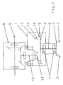
- the rotary harrow has a transversely to the direction of elongated transmission trough 1, are driven in opposite directions rotating tool in a known manner and not shown at intervals to each other, on.
- the tool gyros 2 carry tools 3.
- the Tool gyroscope 2 are driven in opposite directions by means of spur gears 4, which are arranged in the gearbox 1 and mesh with each other, which have external teeth.
- the rotor shafts 6 of the tool gyroscope 2 are mounted by means of bearings 7, which are arranged in the transmission sump 1 welded bearing sleeves.
- the main gear 8 having an angle drive is arranged on the upper side of the gear tray 1.
- the vertical output shaft 10 is driven via the bevel gear 9.
- the pinion 11 is arranged.
- This pinion 11 is in drive connection with a drive wheel 12 assigned to one of the spur gears 4, which has an internal toothing 13 in drive connection.
- the drive ring 12 is formed integrally with the spur gear 4.
- the embodiment according to Fig. 2 differs from the rotary harrow according to Fig. 1 in that the drive ring 14, which has the internal toothing 13, is not integrally connected to the external toothing having spur gear 4, but the inner toothing 13 having outer ring 14 is connected by means of the fastening and coupling elements 15 with the external toothing having spur gear 4.
Landscapes
- Engineering & Computer Science (AREA)
- Life Sciences & Earth Sciences (AREA)
- Power Engineering (AREA)
- Mechanical Engineering (AREA)
- Soil Sciences (AREA)
- Environmental Sciences (AREA)
- Soil Working Implements (AREA)
- Gear Transmission (AREA)
- Plural Heterocyclic Compounds (AREA)
Description
- Die Erfindung betrifft eine Kreiselegge gemäß des Oberbegriffes des Patentanspruches 1 (vgl.
US-A-4 003 439 ). - Eine derartige Kreiselegge ist beispielsweise in der
EP 1 295 520 A2 beschrieben. Bei dieser Kreiselegge ragt das Ritzel des Hauptgetriebes in die Getriebewanne hinein und steht mit der Außenverzahnung eines Stirnrades des die Kreisel antreibenden Stirnradgetriebes in Antriebsverbindung. Die Antriebswelle des Hauptgetriebes, welche das Ritzel trägt, ist in dem Gehäuse des Hauptgetriebes gelagert. Um das Ritzel mit der Außenverzahnung des Hauptgetriebes kämmen zu lassen, muss das Getriebegehäuse eine ausreichende Breite aufweisen, damit das Ritzel mit der Außenverzahnung des Hauptgetriebes kämmen kann. - Der Erfindung liegt die Aufgabe zugrunde, einen Antrieb des Stirnradantriebs einer Kreiselegge über das in die Getriebewanne hineinragende Ritzel zu schaffen, welches nicht mit der Außenverzahnung eines Stirnrades kämmt.
- Diese Aufgabe wird erfindungsgemäß durch die kennzeichnenden Merkmale des Anspruches 1 gelöst.
- Infolge dieser Maßnahme kann das Ritzel des Hauptgetriebes innerhalb des Umlaufkreises des Stirnrades in die Innenverzahnung des dem Stirnrad zugeordneten Antriebselementes eingreifen.
- Hierbei ist auf einem der Zahnräder ein Antriebsring angeordnet, der die Innverzahnung aufweist.
- Hierbei kann der die Innenverzahnung aufweisende Antriebsring einstückig mit dem Stirnrad ausgebildet sein. Hierdurch gibt sich eine preiswerte und kostengünstige Fertigung.
- Auch ist es möglich, dass der Antriebsring mittels Befestigungs- und/oder Kuppelelementen mit dem Stirnrad verbunden ist. Dieses hat den Vorteil, dass das Stirnrad mit der Außenverzahnung unabhängig von dem Stirnrad mit der Innenverzahnung ausgetauscht werden kann, nachdem die Befestigungs- und Kuppelelemente gelöst worden sind.
- Weitere Einzelheiten der Erfindung sind der Beispielsbeschreibung und den Zeichnungen zu entnehmen. Hierbei zeigen
- Fig. 1
- einen Schnitt durch das Hauptgetriebe und die Getriebewanne einer Kreiselegge in schematischer Darstellung, wobei das die Innenverzahnung aufweisenden Zahnrad einstückig mit dem die Außenverzahnung aufweisenden Stirnrad ausgebildet ist und
- Fig. 2
- einen Schnitt durch das Hauptgetriebe und die Getriebewanne einer Kreiselegge in schematischer Darstellung, wobei das die Innenverzahnung aufweisenden Zahnrad mittels Befestigungs- und Kuppelelement mit dem die Außenverzahnung aufweisenden Stirnrad verbunden ist.
- Die Kreiselegge weist eine quer zur Fahrtrichtung lang gestreckte Getriebewanne 1 auf, in der in bekannter und nicht näher dargestellter Weise in Abständen zueinander Werkzeugkreisel 2 gegensinnig rotierend angetrieben sind, auf. Die Werkzeugkreisel 2 tragen Werkzeuge 3. Die Werkzeugkreisel 2 werden über in der Getriebewanne 1 angeordnete und ineinander greifende Stirnräder 4, die eine Außenverzahnung aufweisen, des Stirnradgetriebes 5 gegensinnig rotierend angetrieben. Die Rotorwellen 6 der Werkzeugkreisel 2 sind mittels Lager 7, die in der Getriebewanne 1 eingeschweißte Lagerhülsen angeordnet sind, gelagert.
- Um die Stirnräder 4 der Kreiselegge anzutreiben, ist auf der Oberseite der Getriebewanne 1 das einen Winkeltrieb aufweisende Hauptgetriebe 8 angeordnet. Über die Antriebswelle 9, die mittels einer nicht dargestellten Gelenkwelle an einen die Kreiselegge ziehenden Schlepper angeschlossen ist, wird über den Kegelradtrieb 9 die senkrechte Abtriebswelle 10 angetrieben. Am unteren Ende der Abtriebswelle 10 ist das Ritzel 11 angeordnet. Dieses Ritzel 11 steht in Antriebsverbindung mit einem auf einem der Stirnräder 4 zugeordneten Antriebsring 12, der eine Innenverzahnung 13 aufweist, in Antriebsverbindung. Somit können über das Hauptgetriebe 8 das Stirnradgetriebe 5 die Werkzeugkreisel 2 angetrieben werden. Der Antriebsring 12 ist einstückig mit dem Stirnrad 4 ausgebildet.
- Die Ausgestaltung gemäß
Fig. 2 unterscheidet sich von der Kreiselegge gemäßFig. 1 dadurch, dass der Antriebsring 14, der die Innenverzahnung 13 aufweist, nicht einstückig mit dem die Außenverzahnung aufweisenden Stirnrad 4 verbunden ist, sondern der die Innenverzahnung 13 aufweisende Außenring 14 ist mittels dem Befestigungs- und Kuppelelementen 15 mit dem die Außenverzahnung aufweisenden Stirnrad 4 verbunden.
Claims (3)
- Kreiselegge mit Getriebewanne (1) mit mehreren Stirnrädern, die drehfest mit Rotorwellen (6) verbunden sind, die wiederum in der Getriebewanne (1) mittels Lager (7) gelagert sind, wobei die einzelnen Stirnräder (4) nebeneinander angeordnet sind und über ihre Außenverzahnung miteinander im Eingriff stehen, mit einem oberhalb der Getriebewanne (1) angeordneten Hauptgetriebe (8), welches eine vertikal angeordnete Antriebswelle (10) für den Antrieb der Stirnräder (4) in der Getriebewanne (1) aufweist, wobei die Antriebswelle (10) in die Getriebewanne (1) hineinragt und endseitig ein Ritzel (11) aufweist und eines der Stirnräder (4) antreibt, dadurch gekennzeichnet, dass eines der Stirnräder (4) zusätzlich zu der Außenverzahnung eine mit dem Ritzel (11) der Antriebswelle (10) im Eingriff stehende Innenverzahnung (13) aufweist, dass auf einem der Stirnräder (4) ein die Innenverzahnung (13) aufweisender Antriebsring (12,14) angeordnet ist.
- Kreiselegge nach Anspruch 1, dadurch gekennzeichnet, dass der Antriebsring (12) einstückig mit dem Stirnrad (4) ausgebildet ist.
- Kreiselegge nach Anspruch 2, dadurch gekennzeichnet, dass der Antriebsring (14) mittels Befestigungs- und/oder Kuppelelementen (15) mit dem Stirnrad (4) verbunden ist.
Applications Claiming Priority (1)
| Application Number | Priority Date | Filing Date | Title |
|---|---|---|---|
| DE102005039027A DE102005039027A1 (de) | 2005-08-18 | 2005-08-18 | Kreiselegge |
Publications (2)
| Publication Number | Publication Date |
|---|---|
| EP1754403A1 EP1754403A1 (de) | 2007-02-21 |
| EP1754403B1 true EP1754403B1 (de) | 2009-03-25 |
Family
ID=37438036
Family Applications (1)
| Application Number | Title | Priority Date | Filing Date |
|---|---|---|---|
| EP06016051A Not-in-force EP1754403B1 (de) | 2005-08-18 | 2006-08-02 | Kreiselegge |
Country Status (3)
| Country | Link |
|---|---|
| EP (1) | EP1754403B1 (de) |
| AT (1) | ATE426322T1 (de) |
| DE (2) | DE102005039027A1 (de) |
Families Citing this family (3)
| Publication number | Priority date | Publication date | Assignee | Title |
|---|---|---|---|---|
| DE202010002275U1 (de) | 2010-02-12 | 2011-08-26 | Alois Pöttinger Maschinenfabrik Gmbh | Landmaschine |
| CN102763504A (zh) * | 2012-07-13 | 2012-11-07 | 江伟 | 微耕机箱体 |
| CN104429192A (zh) * | 2014-12-08 | 2015-03-25 | 王汉发 | 一种微耕机行走变速箱 |
Family Cites Families (5)
| Publication number | Priority date | Publication date | Assignee | Title |
|---|---|---|---|---|
| NL7406084A (nl) * | 1974-05-07 | 1975-11-11 | Lely Nv C Van Der | Grondbewerkingsmachine. |
| NL7510538A (nl) * | 1975-09-08 | 1977-03-10 | Lely Nv C Van Der | Grondbewerkingsmachine of dergelijke machine. |
| NL8202359A (nl) * | 1982-06-11 | 1984-01-02 | Lely Nv C Van Der | Grondbewerkingsmachine. |
| NL8300913A (nl) * | 1983-03-14 | 1984-10-01 | Texas Industries Inc | Grondbewerkingsmachine. |
| DE50214020D1 (de) | 2001-09-21 | 2010-01-07 | Lemken Gmbh & Co Kg | Kreiselegge mit verbessertem Rotorantrieb |
-
2005
- 2005-08-18 DE DE102005039027A patent/DE102005039027A1/de not_active Withdrawn
-
2006
- 2006-08-02 DE DE502006003237T patent/DE502006003237D1/de active Active
- 2006-08-02 AT AT06016051T patent/ATE426322T1/de not_active IP Right Cessation
- 2006-08-02 EP EP06016051A patent/EP1754403B1/de not_active Not-in-force
Also Published As
| Publication number | Publication date |
|---|---|
| DE102005039027A1 (de) | 2007-02-22 |
| EP1754403A1 (de) | 2007-02-21 |
| ATE426322T1 (de) | 2009-04-15 |
| DE502006003237D1 (de) | 2009-05-07 |
Similar Documents
| Publication | Publication Date | Title |
|---|---|---|
| DE102018128836B3 (de) | Getriebevorrichtung für ein Kraftfahrzeug | |
| DE2541726A1 (de) | Getriebe fuer den hauptrotor eines hubschraubers mit auswechselbarer freilaufkupplung | |
| DE10159973A1 (de) | Getriebe für eine Windkraftanlage | |
| WO2016004937A1 (de) | Antriebsanordnung mit einem wälzenden differential | |
| EP3464894B1 (de) | Windkraftgetriebe | |
| EP0712753A2 (de) | Wechselgetriebe für Kraftfahrzeuge mit einer vorn eingebauten, querliegenden Antriebseinheit | |
| DE19854215B4 (de) | Differentialgetriebeeinheit für Kraftfahrzeuge | |
| DE102011121795B4 (de) | Antriebseinheit für ein lenkbares Laufrad | |
| EP1574120B1 (de) | Kreiselegge | |
| DE102018101410B3 (de) | Antriebsvorrichtung mit einer elektrischen Maschine und einem Hohlradtopf | |
| EP1754403A1 (de) | Kreiselegge | |
| DE102016003953B4 (de) | Gelenkstruktur für einen Roboter mit Motor und Reduktionsgetriebe | |
| AT523435B1 (de) | Radantriebsmodul zum Antrieb und zur Lenkung eines Rades | |
| DE102018127721B4 (de) | Getriebevorrichtung für ein Kraftfahrzeug | |
| EP1754404B1 (de) | Kreiselegge | |
| DE102015220522B4 (de) | Schmal bauendes Differenzialgetriebe mit großen Seitenrädern | |
| EP1295520B1 (de) | Kreiselegge mit verbessertem Rotorantrieb | |
| DE102014226046B4 (de) | Wolfrom-Getriebe mit dreifach verzahnten Planeten für eine Windkraftanlage und Verfahren zur Montage von Lagern eines solchen Getriebes | |
| DE102018128837A1 (de) | Getriebevorrichtung für ein Kraftfahrzeug | |
| WO2012084303A1 (de) | Antriebsvorrichtung für kraftfahrzeuge | |
| EP2123142B1 (de) | Kreiselegge | |
| EP1568916B1 (de) | Wechselradgetriebe | |
| EP1839840B1 (de) | Antriebs-Einheit für eine Zwei-Schnecken-Maschine | |
| DE102018128833B4 (de) | Getriebevorrichtung für ein Kraftfahrzeug | |
| DE102018131488B4 (de) | Getriebevorrichtung für ein Kraftfahrzeug |
Legal Events
| Date | Code | Title | Description |
|---|---|---|---|
| PUAI | Public reference made under article 153(3) epc to a published international application that has entered the european phase |
Free format text: ORIGINAL CODE: 0009012 |
|
| AK | Designated contracting states |
Kind code of ref document: A1 Designated state(s): AT BE BG CH CY CZ DE DK EE ES FI FR GB GR HU IE IS IT LI LT LU LV MC NL PL PT RO SE SI SK TR |
|
| AX | Request for extension of the european patent |
Extension state: AL BA HR MK YU |
|
| 17P | Request for examination filed |
Effective date: 20070809 |
|
| AKX | Designation fees paid |
Designated state(s): AT BE BG CH CY CZ DE DK EE ES FI FR GB GR HU IE IS IT LI LT LU LV MC NL PL PT RO SE SI SK TR |
|
| 17Q | First examination report despatched |
Effective date: 20070927 |
|
| GRAP | Despatch of communication of intention to grant a patent |
Free format text: ORIGINAL CODE: EPIDOSNIGR1 |
|
| GRAS | Grant fee paid |
Free format text: ORIGINAL CODE: EPIDOSNIGR3 |
|
| GRAA | (expected) grant |
Free format text: ORIGINAL CODE: 0009210 |
|
| AK | Designated contracting states |
Kind code of ref document: B1 Designated state(s): AT BE BG CH CY CZ DE DK EE ES FI FR GB GR HU IE IS IT LI LT LU LV MC NL PL PT RO SE SI SK TR |
|
| REG | Reference to a national code |
Ref country code: GB Ref legal event code: FG4D Free format text: NOT ENGLISH |
|
| REG | Reference to a national code |
Ref country code: CH Ref legal event code: EP |
|
| REG | Reference to a national code |
Ref country code: IE Ref legal event code: FG4D Free format text: LANGUAGE OF EP DOCUMENT: GERMAN |
|
| REF | Corresponds to: |
Ref document number: 502006003237 Country of ref document: DE Date of ref document: 20090507 Kind code of ref document: P |
|
| PG25 | Lapsed in a contracting state [announced via postgrant information from national office to epo] |
Ref country code: SI Free format text: LAPSE BECAUSE OF FAILURE TO SUBMIT A TRANSLATION OF THE DESCRIPTION OR TO PAY THE FEE WITHIN THE PRESCRIBED TIME-LIMIT Effective date: 20090325 Ref country code: FI Free format text: LAPSE BECAUSE OF FAILURE TO SUBMIT A TRANSLATION OF THE DESCRIPTION OR TO PAY THE FEE WITHIN THE PRESCRIBED TIME-LIMIT Effective date: 20090325 Ref country code: LT Free format text: LAPSE BECAUSE OF FAILURE TO SUBMIT A TRANSLATION OF THE DESCRIPTION OR TO PAY THE FEE WITHIN THE PRESCRIBED TIME-LIMIT Effective date: 20090325 |
|
| PG25 | Lapsed in a contracting state [announced via postgrant information from national office to epo] |
Ref country code: LV Free format text: LAPSE BECAUSE OF FAILURE TO SUBMIT A TRANSLATION OF THE DESCRIPTION OR TO PAY THE FEE WITHIN THE PRESCRIBED TIME-LIMIT Effective date: 20090325 Ref country code: SE Free format text: LAPSE BECAUSE OF FAILURE TO SUBMIT A TRANSLATION OF THE DESCRIPTION OR TO PAY THE FEE WITHIN THE PRESCRIBED TIME-LIMIT Effective date: 20090625 Ref country code: PL Free format text: LAPSE BECAUSE OF FAILURE TO SUBMIT A TRANSLATION OF THE DESCRIPTION OR TO PAY THE FEE WITHIN THE PRESCRIBED TIME-LIMIT Effective date: 20090325 |
|
| NLV1 | Nl: lapsed or annulled due to failure to fulfill the requirements of art. 29p and 29m of the patents act | ||
| REG | Reference to a national code |
Ref country code: IE Ref legal event code: FD4D |
|
| PG25 | Lapsed in a contracting state [announced via postgrant information from national office to epo] |
Ref country code: ES Free format text: LAPSE BECAUSE OF FAILURE TO SUBMIT A TRANSLATION OF THE DESCRIPTION OR TO PAY THE FEE WITHIN THE PRESCRIBED TIME-LIMIT Effective date: 20090706 Ref country code: CZ Free format text: LAPSE BECAUSE OF FAILURE TO SUBMIT A TRANSLATION OF THE DESCRIPTION OR TO PAY THE FEE WITHIN THE PRESCRIBED TIME-LIMIT Effective date: 20090325 Ref country code: PT Free format text: LAPSE BECAUSE OF FAILURE TO SUBMIT A TRANSLATION OF THE DESCRIPTION OR TO PAY THE FEE WITHIN THE PRESCRIBED TIME-LIMIT Effective date: 20090901 Ref country code: EE Free format text: LAPSE BECAUSE OF FAILURE TO SUBMIT A TRANSLATION OF THE DESCRIPTION OR TO PAY THE FEE WITHIN THE PRESCRIBED TIME-LIMIT Effective date: 20090325 |
|
| PG25 | Lapsed in a contracting state [announced via postgrant information from national office to epo] |
Ref country code: SK Free format text: LAPSE BECAUSE OF FAILURE TO SUBMIT A TRANSLATION OF THE DESCRIPTION OR TO PAY THE FEE WITHIN THE PRESCRIBED TIME-LIMIT Effective date: 20090325 Ref country code: RO Free format text: LAPSE BECAUSE OF FAILURE TO SUBMIT A TRANSLATION OF THE DESCRIPTION OR TO PAY THE FEE WITHIN THE PRESCRIBED TIME-LIMIT Effective date: 20090325 Ref country code: IS Free format text: LAPSE BECAUSE OF FAILURE TO SUBMIT A TRANSLATION OF THE DESCRIPTION OR TO PAY THE FEE WITHIN THE PRESCRIBED TIME-LIMIT Effective date: 20090725 Ref country code: NL Free format text: LAPSE BECAUSE OF FAILURE TO SUBMIT A TRANSLATION OF THE DESCRIPTION OR TO PAY THE FEE WITHIN THE PRESCRIBED TIME-LIMIT Effective date: 20090325 |
|
| PG25 | Lapsed in a contracting state [announced via postgrant information from national office to epo] |
Ref country code: DK Free format text: LAPSE BECAUSE OF FAILURE TO SUBMIT A TRANSLATION OF THE DESCRIPTION OR TO PAY THE FEE WITHIN THE PRESCRIBED TIME-LIMIT Effective date: 20090325 Ref country code: IE Free format text: LAPSE BECAUSE OF FAILURE TO SUBMIT A TRANSLATION OF THE DESCRIPTION OR TO PAY THE FEE WITHIN THE PRESCRIBED TIME-LIMIT Effective date: 20090325 Ref country code: BG Free format text: LAPSE BECAUSE OF FAILURE TO SUBMIT A TRANSLATION OF THE DESCRIPTION OR TO PAY THE FEE WITHIN THE PRESCRIBED TIME-LIMIT Effective date: 20090625 |
|
| PLBE | No opposition filed within time limit |
Free format text: ORIGINAL CODE: 0009261 |
|
| STAA | Information on the status of an ep patent application or granted ep patent |
Free format text: STATUS: NO OPPOSITION FILED WITHIN TIME LIMIT |
|
| BERE | Be: lapsed |
Owner name: AMAZONEN-WERKE H. DREYER G.M.B.H. & CO. KG Effective date: 20090831 |
|
| 26N | No opposition filed |
Effective date: 20091229 |
|
| PG25 | Lapsed in a contracting state [announced via postgrant information from national office to epo] |
Ref country code: MC Free format text: LAPSE BECAUSE OF NON-PAYMENT OF DUE FEES Effective date: 20090831 |
|
| REG | Reference to a national code |
Ref country code: FR Ref legal event code: ST Effective date: 20100430 |
|
| PG25 | Lapsed in a contracting state [announced via postgrant information from national office to epo] |
Ref country code: BE Free format text: LAPSE BECAUSE OF NON-PAYMENT OF DUE FEES Effective date: 20090831 |
|
| PG25 | Lapsed in a contracting state [announced via postgrant information from national office to epo] |
Ref country code: FR Free format text: LAPSE BECAUSE OF NON-PAYMENT OF DUE FEES Effective date: 20090831 |
|
| PG25 | Lapsed in a contracting state [announced via postgrant information from national office to epo] |
Ref country code: GR Free format text: LAPSE BECAUSE OF FAILURE TO SUBMIT A TRANSLATION OF THE DESCRIPTION OR TO PAY THE FEE WITHIN THE PRESCRIBED TIME-LIMIT Effective date: 20090626 |
|
| PG25 | Lapsed in a contracting state [announced via postgrant information from national office to epo] |
Ref country code: AT Free format text: LAPSE BECAUSE OF NON-PAYMENT OF DUE FEES Effective date: 20090802 |
|
| PG25 | Lapsed in a contracting state [announced via postgrant information from national office to epo] |
Ref country code: IT Free format text: LAPSE BECAUSE OF FAILURE TO SUBMIT A TRANSLATION OF THE DESCRIPTION OR TO PAY THE FEE WITHIN THE PRESCRIBED TIME-LIMIT Effective date: 20090325 |
|
| REG | Reference to a national code |
Ref country code: CH Ref legal event code: PL |
|
| GBPC | Gb: european patent ceased through non-payment of renewal fee |
Effective date: 20100802 |
|
| PG25 | Lapsed in a contracting state [announced via postgrant information from national office to epo] |
Ref country code: LU Free format text: LAPSE BECAUSE OF NON-PAYMENT OF DUE FEES Effective date: 20090802 Ref country code: LI Free format text: LAPSE BECAUSE OF NON-PAYMENT OF DUE FEES Effective date: 20100831 Ref country code: CH Free format text: LAPSE BECAUSE OF NON-PAYMENT OF DUE FEES Effective date: 20100831 |
|
| PG25 | Lapsed in a contracting state [announced via postgrant information from national office to epo] |
Ref country code: HU Free format text: LAPSE BECAUSE OF FAILURE TO SUBMIT A TRANSLATION OF THE DESCRIPTION OR TO PAY THE FEE WITHIN THE PRESCRIBED TIME-LIMIT Effective date: 20090926 |
|
| PG25 | Lapsed in a contracting state [announced via postgrant information from national office to epo] |
Ref country code: GB Free format text: LAPSE BECAUSE OF NON-PAYMENT OF DUE FEES Effective date: 20100802 Ref country code: TR Free format text: LAPSE BECAUSE OF FAILURE TO SUBMIT A TRANSLATION OF THE DESCRIPTION OR TO PAY THE FEE WITHIN THE PRESCRIBED TIME-LIMIT Effective date: 20090325 |
|
| PG25 | Lapsed in a contracting state [announced via postgrant information from national office to epo] |
Ref country code: CY Free format text: LAPSE BECAUSE OF FAILURE TO SUBMIT A TRANSLATION OF THE DESCRIPTION OR TO PAY THE FEE WITHIN THE PRESCRIBED TIME-LIMIT Effective date: 20090325 |
|
| PGFP | Annual fee paid to national office [announced via postgrant information from national office to epo] |
Ref country code: DE Payment date: 20190723 Year of fee payment: 14 |
|
| REG | Reference to a national code |
Ref country code: DE Ref legal event code: R119 Ref document number: 502006003237 Country of ref document: DE |
|
| PG25 | Lapsed in a contracting state [announced via postgrant information from national office to epo] |
Ref country code: DE Free format text: LAPSE BECAUSE OF NON-PAYMENT OF DUE FEES Effective date: 20210302 |