EP1754200B1 - Procede, programme d'ordinateur, appareil et systeme d'imagerie servant a traiter une image - Google Patents
Procede, programme d'ordinateur, appareil et systeme d'imagerie servant a traiter une image Download PDFInfo
- Publication number
- EP1754200B1 EP1754200B1 EP05742380.8A EP05742380A EP1754200B1 EP 1754200 B1 EP1754200 B1 EP 1754200B1 EP 05742380 A EP05742380 A EP 05742380A EP 1754200 B1 EP1754200 B1 EP 1754200B1
- Authority
- EP
- European Patent Office
- Prior art keywords
- value
- image
- detail
- positioning error
- image processing
- Prior art date
- Legal status (The legal status is an assumption and is not a legal conclusion. Google has not performed a legal analysis and makes no representation as to the accuracy of the status listed.)
- Active
Links
Images


Classifications
-
- G—PHYSICS
- G06—COMPUTING; CALCULATING OR COUNTING
- G06T—IMAGE DATA PROCESSING OR GENERATION, IN GENERAL
- G06T19/00—Manipulating 3D models or images for computer graphics
-
- G—PHYSICS
- G06—COMPUTING; CALCULATING OR COUNTING
- G06T—IMAGE DATA PROCESSING OR GENERATION, IN GENERAL
- G06T2219/00—Indexing scheme for manipulating 3D models or images for computer graphics
- G06T2219/012—Dimensioning, tolerancing
Definitions
- the invention relates to a method for processing an image, comprising the step of:
- the invention further relates to a computer program.
- the invention still further relates to an apparatus arranged for image processing, said apparatus comprising:
- the invention still further relates to an imaging system.
- Document Of Cavallo et al. "A Hybrid Approach to the 3D High Precision Position Measurement and Particle Tracking in Human Cell Nuclei", in Real-Time Imaging, Vol. 8, Pages 467-473 (2002 ) discloses locating an object within an image with better precision by allowing manual adjustment of a segmentation threshold. It does not disclose or make use of of any uncertainties regarding the localization of the object.
- the known method is arranged to enable an elastic registration of three-dimensional tomographic images, said registration being based on a set of corresponding anatomical landmarks taking into account anisotropic landmark localization errors in form of three-dimensional error ellipsoids.
- a two-dimensional slice of a human brain comprising suitable details may be produced based on a volumetric data acquired using magnetic resonance apparatus.
- the known method is further arranged to assign respective values of positioning errors to suitable details in the image. This feature of the known method is based on a per se known method of non-rigid matching of medical images using approximating thin-plate splines.
- the known method is arranged to estimate three-dimensional covariance matrices at landmarks directly from the image data.
- the corresponding error ellipsoids are visualized in the image and are arranged to characterize the local intensity variations at a detail under consideration, thus yielding corresponding values for respective positioning errors of the details.
- the method according to the invention comprises the further steps of:
- the user is enabled to adjust the value of the positioning error assigned to the detail under consideration in an interactive way, thus bringing in his expertise, if required. he initial assignment of the value may be carried out manually or automatically.
- the (adjusted) value is stored with reference to the position of the detail and is used during further steps of image processing.
- the reliability of the further image processing steps is improved.
- the value of the positionining error equals a default value assigned to an imaging modality. In this case all details within the image are assigned this default value, which is stored with reference to every position of every detail in the image. The user may then alter this default value, which in this case will be overwritten by a value given by the user.
- the technical measure of the invention is based on the insight that in particular measurements and computations carried out based on raw image data, notably of medical origin completely ignore respective accuracies of positioning of the details within the image.
- the term 'detail' hereby refers to a pixel or a voxel indicative, for example of a structure of an object being imaged, suitable example comprising a structure within a human anatomy.
- the term 'detail' may refer to a further object within the image, for example a medical instrument, or the like.
- knowledge of the accuracy of the positioning of the details within the image is required.
- the accuracy is a distribution of probabilities, for example a normal distribution around a point.
- the accuracy may be anisotropic, for example rotation-dependent.
- Distributions that can be parameterized can be interacted with in a simple way.
- the normal distribution is normally parameterized with a sigma, which can be visualized with a circle in case of a 2D point being a detail under consideration. The radius of this circle equals the sigma. In the case of a 3D point, a sphere might be used to indicate the sigma.
- the visualization might be a rectangle, where the width of the rectangle represents the sigma of the x component and the height of the rectangle represents the sigma of the y component.
- Visualization of a distribution is not limited to graphical objects: text and/or numbers on the output device are perfectly capable in describing a distribution, for example the text '3.05 ⁇ 0.45 mm' might indicate a uniform distribution from 2.60 mm up to and including 3.50 mm.
- suitable graphic means in case the visualization is graphic. Otherwise, the user may turn to suitable input means to enter the value of the positioning error of the detail under consideration.
- the method further comprises the steps of:
- This technical measure is particularly advantageous for situations, where the value of the positioning error is not assigned to each relevant detail identifiable in the image.
- the user may introduce the value of the positioning error to a new selected detail, whereby the absolute value of the positioning error may be copied from a neighbor detail, or it may be based on an expertise of the user.
- the user is not only enabled to define respective values of the positioning errors of relevant further details within the image, but also to use these values during further steps of image processing, because the corresponding values of the positioning errors are stored with reference to the respective positions of the further details under consideration.
- the method further comprises the steps of:
- suitable per se known algorithms for image processing may automatically assign a suitable parameter distinguishing between blurry edges in the image and sharp edges in the image, this parameter being used to automatically compute corresponding values of the positioning errors.
- the user may still edit the computed value, still improving the reliability of the image analysis.
- said image is overlaid with a graphic template of the detail, said graphic template being defined within an image processing tool.
- Such further processing may include, for example a delineation of details of interest.
- Such delineation may comprise a delineation of structures within the image, for example delineation of suitable anatomical sites.
- said delineation may comprise a delineation of further objects identifiable in the image, like, for example surgical instruments, catheters or the like.
- the details to be delineated are automatically overlaid with suitable graphic templates, whereby geometric matching between the templates and the details is carried out using suitable per se known image matching techniques.
- the geometric template is defined within a suitable image processing tool
- the value of the positioning error assigned to the detail is automatically taken into account during the step of delineation of an area based on a plurality of pixels or voxels each having its respective position within the image and the value of the positioning error within the image.
- the delineated area or volume is characterized by its positioning error using suitable error propagation algorithm.
- the reliability of the further image processing step is improved.
- suitable landmarks linked to the details can be used as input for a more complex measurement.
- Complex measurements are measurements which are built on top of other measurements. For example, an angle between two lines might be build up of a line, and a line, and the angle-between-lines. A line might be build up by landmarks for start and end. Combining complex measurements with landmarks-with-inaccuracy yields a complex measurement which takes the accuracy into account. For example, two landmarks can determine a line by its start and by its end. If the landmark have an ellipse as location error distribution and we are interested in the angle of the line, the resulting line would be a line with added with an inaccuracy of the angle.
- this new angle measurement has a new inaccuracy determined by the inaccuracy of the two lines combined.
- initial errors in the positioning of the details are taken into account and their propagation into a measurement result is taken into account accordingly.
- the graphic template is defined within a geometric relational application framework macro.
- This technical measure is advantageous, as the graphic relational application macro can be configured to interrelate a plurality of objects in such a way, that when a single object is repositioned, the other objects related to it are repositioned accordingly.
- the geometric application framework macro is arranged to provide detailed descriptions of various geometric templates defined within the image, in particular to structurally interrelate said templates within geometry of the image, thus providing a structural handling of various geometrical templates so that a certain pre-defined geometrical consistency between the templates is maintained.
- the geometric application framework macro further enables analysis and/or measurement of geometrical properties of anatomical structures, when the structure is provided with a suitable landmark.
- a broad variety of possible geometric relations between pre-definable geometric templates, like a circle, a line, a sphere, etc., is possible and is defined within the geometric application framework macro.
- the geometric template is operable by the geometric application framework macro using a landmark, or a set of landmarks associated with the geometric template.
- the computer program according to the invention is arranged to cause the processor to carry out the steps of the method as are set forth in the foregoing.
- the apparatus according to the invention further comprises interactive means arranged to enable an adjustment of said value by a user, the computing means being further arranged to store the value of the positioning error with reference to the position of the detail.
- the user is enabled to edit and/or to append the relevant details identified within the image with a suitable accuracy of the positioning of the detail, whereby this accuracy is further taken into consideration during further steps of image processing.
- the accuracy is visualized using suitable graphic means, for example by drawing a geometric figure corresponding to the positioning uncertainty and/or, alternatively by linking an interactive text-box feeding back the value of the positioning error to the user.
- An imaging system comprises a display means and the apparatus, as is set forth in the foregoing.
- the imaging system according to the invention further comprises a data acquisition unit connectable to the image processing apparatus. In this way an easy to operate data acquisition and processing system is provided, whereby the user is enabled to carry out necessary image processing steps with high reliability.
- Fig. 1 presents in a schematic way an embodiment of a method according to the invention whereby a measurement with reference to image details provided with an identification of the positioning error is carried out.
- the image 1 comprises a diagnostic medical image, other images are contemplated as well.
- the method according to the invention will be explained using two consecutive steps 1a and 1b.
- the image 1 comprises an area of a human anatomy wherein two details 2a and 2b are identified.
- the details are positioned to coincide with an exterior of a femoral bone 3.
- the details 2a, 2b may be positioned manually or in an automatic way using, for example edge detection algorithm.
- each detail is assigned a value of a positioning error, which is visualized to the user, for example by means of suitable ellipses 4a and 4b.
- the respective values of the positioning error may be introduced manually by the user using suitable input means.
- the value of the positioning error is assigned to the detail based on a parameter indicative of the image quality.
- an edge detection algorithm may be suitably arranged to evaluate the gradient along the edge of the femoral bone, the value of the positioning error being deduced from the gradient.
- every pixel within the image is assigned an initial default value of the positioning error, which corresponds, for example to an imaging modality the image 1 has been acquired from.
- the user is provided with means to adjust the value of the positioning error interactively.
- the user may use the cursor 8 to drag the respective boundaries of the ellipses, thus changing the corresponding value of the positioning error.
- the user may use a suitable input means, like a keyboard to enter the absolute value of the positioning error directly.
- the value of the positioning error is stored together with the coordinate of the detail within the image.
- the result of the measurement is provided with an uncertainty value derived from the values of the positioning error. This is schematically illustrated in window 9, arranged to feed back a result of a measurement of a distance between image details 2a and 2b.
- the user may adjust the assigned value of the positioning error, in case his expertise dictates so. This is schematically illustrated at step 1b.
- the user has redefined the areas of the positioning errors for the details 2a and 2b, enlarging them to 4a', 4b'.
- the corresponding reading of the measurement uncertainty, shown in window 9b, is changed accordingly.
- the method according to the invention is advantageous as it provides means to include positioning uncertainties into an error propagation calculation. This is of particular relevance in case an area or a volume of interest is to be delineated, for example for purposes of preparing a radiotherapy treatment plan.
- an area or a volume of interest is to be delineated, for example for purposes of preparing a radiotherapy treatment plan.
- the user may delineate the volume of interest manually, or it may be delineated automatically based on pixel or voxel values.
- the resulting volume will be appended with the information on the delineation error calculated based on the positioning errors of the details constituting the volume of interest.
- the delineated volume of interest is enlarged by a margin covering for the greatest deviation, thus ensuring that the radiotherapy planning is carried out accurately covering for possible image processing uncertainties.
- Fig. 2 presents in a schematic way a further embodiment of a method according to the invention whereby an image handling with reference to image details provided with an identification of the positioning error is carried out.
- the image 10 comprises a diagnostic X-ray image showing a part of a human bone. This image may be used for planning a surgery, notably an orthopedic intervention. For this purpose it might be useful to determine a point of intersection between a first centerline 12 of a femur head with a second centerline 14 of the femur head. It is possible, that the image 10 is provided with automatically delineated details 12a and 12b, defining the first centerline 12.
- the details 12a, 12b are provided with respective visualized positioning errors 12b, 12c.
- the user may define the second centerline 14, by identifying further details 14a, 14b and by identifying corresponding positioning errors 14b, 14c, respectively.
- the intersection of the lines 12, 14 is illustrated by a point 16, which is provided with a positioning error indication 16a, given by a suitable ellipsoid.
- the value and the shape of the positioning error indicator 16a is dependent on the absolute values of the four respective positioning errors of the details and the distribution thereof. Usually, for the same image the distribution will be the same, like a uniform distribution, or a normal distribution. For the same type of distributions the indicator 16a will usually have the same shape as the indicators of the positioning errors of the details.
- the indicator 16a may have an irregular shape, it being determined by a convolution of different distributions.
- Figure 3 presents in a schematic way an embodiment of a method according to the invention whereby a detail is overlaid by a graphic template.
- the graphic template comprises a measurement tool arranged within a geometric relational application framework macro
- other suitable graphic templates are possible.
- an automatic diameter measurement of a human femur is shown.
- the solid lines 32, 34 represent graphic templates within the geometric relational application framework macro: a line 32 modeling the femoral axis, a second perpendicular line 34 modeling a direction of a diameter measurement 35.
- the structure of the geometric relational application framework macro is known per se from WO/0063844 .
- the perpendicular line 34 is arranged to contain two graphic templates, namely two point objects 33a, 33b with an associated distance measurement, all being defined within the geometric relational application framework macro.
- open contours 31 are associated with the points 33a, 33b. These contours position themselves automatically along the edges of the femoral bone using a suitable image segmentation technique.
- the positions of the two point objects 33a, 33b are automatically adapted to the intersection of the perpendicular line 34 and each graphic object 31.
- This embodiment is arranged to determine the distance between the points 33a, 33b.
- the points 33a, 33b are provided with corresponding positioning error indicators 33a', 33b'.
- These values may be input by the user using an interactive text editor in a window 37a.
- This example shows rectangles visualizing the positioning errors, as hereby it is judged that the positioning error in first direction does not equal a positioning error in a second direction.
- the corresponding value of the distance and the uncertainty therein is shown in the window 36.
- the reading in window 36 is updated automatically due to an advantageous combination of functionality of the geometric relational application framework macro and the method of the invention.
- the reading of the distance 36 is automatically updated in case when a position of any of the lines 31, 32, 34 is changed, leading to a different reading of a length for a trajectory 35 between new points 33a and 33b.
- the diameter measurement 35 will adapt dependent on the current femur diameter at a new location of the perpendicular line 34.
- a versatile and easy to operate image processing means is provided, whereby due to coupling between the graphic objects in a geometric relational application framework macro, any repositioning of the objects automatically lead to an update of the measurement of the object of interest 35, appended with a corresponding accuracy value.
- Fig. 4 presents in a schematic way an embodiment of an apparatus according to the invention.
- the image processing apparatus 40 has an input 42 for receiving the image data in any suitable form.
- the apparatus 40 may be involved in the acquisition of the image data.
- the image data may be acquired in an analogue form and converted using a suitable A/D converter to a digital form for further processing.
- the image data may also be received in a digital form, e.g. through direct acquisition in a digital form or via a computer network after having been acquired by another computer/medical instrument.
- the core of the image processing apparatus is formed by a processor 44 which is arranged to load image data from the input means 42 and made these data available for further processing.
- An example of a suitable processor 44 is a conventional microprocessor or signal processor, a background storage 48 (typically based on a hard disk) and working memory 46 (typically based on RAM).
- the background storage 48 can be used for storing the image data (or parts of it) when not being processed, and for storing operations of the graphic template and suitable shape models (when not being executed by the processor).
- the main memory 46 typically holds the (parts of) image data being processed and the instructions of the geometric template and the models used for processing those parts of the image data.
- the apparatus 40 comprises computing means 45 arranged to assign a value of the positioning error to a detail in the image.
- the computing means may be arranged to assign said value automatically, for example based on a default value applicable to the image as a whole, or to calculate a parameter wherefrom the value of the positioning error is deduced.
- the apparatus further comprises visualization means 47 arranged to visualize the value of the positioning error.
- the visualization means 47 may be arranged to provide a textual feed-back of respective positioning errors continuously, or on demand, when a user selects a detail.
- the visualization means is arranged to graphically visualize the positioning error in the image by means of suitable geometric shapes.
- the apparatus 40 further comprises interactive means 47a, arranged to enable an adjustment of the value of the positioning error by a user. Various embodiments of the interactive means 47a are envisaged.
- a file reader for reading a default value from a file provided by the user, a graphic user interface enabling the user to draw respective indicators of the positioning errors, a text editor, an interactive window, or the like.
- computing means 45, visualization 47 and the interactive means 47a are operable by a computer program 43, preferably stored in memory 48.
- An output 49 is used for outputting the result of a suitable data processing, like a measurement result, a delineation of an area or a volume of interest, or the like.
- the output may be a segmented structure with the volume of interest provided with a positioning margin, calculated based on the positioning errors of the details constituting the volume of interest.
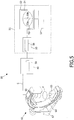
- Fig. 5 presents in a schematic way an embodiment of an imaging system according to the invention.
- the imaging system 50 according to the invention comprises the apparatus 40 arranged for image processing based on an image data 59.
- the output of the apparatus 40 preferably comprises an image with at least one detail provided with a value of the positioning error stored with reference to a position of the detail in the image.
- the output of the apparatus 40 is made available to the further input means 55 of a viewer 51.
- the further input means 55 comprises a suitable further processing means arranged to operate a suitable interface using a program 56 adapted to control the user interface 54 so that an image 53 comprising suitable detail 53b associated with the positioning error thereof 53a is visualized.
- the viewer 51 is provided with a high-resolution display means 52, the user interface being operable by means of a suitable interactive means 57, for example a mouse, a keyboard or any other suitable user's input device.
- the image analysis system 50 further comprises a data acquisition unit 61.
- a data acquisition unit 61 is arranged to acquire image data from an object, for example a patient, positioned in an acquisition volume V of the apparatus 61.
- a beam of X-rays (not shown) is emitted from the X-ray source 63.
- the transmitted radiation (not shown) is registered by a suitable detector 65.
- the X-ray source 63 and the X-ray detector 65 are mounted on a gantry 64 which is rotatably connected to a stand 67.
- a signal S at the output of the X-ray detector 65 is representative of the image data 59.
- Fig. 6 presents in a schematic way an embodiment of a work-flow of the method according to the invention.
- a suitable detail 74a is assigned a value of the positioning error.
- the value of the positioning error is loaded from a suitable file 75, corresponding, for example to positional inaccuracies of a certain imaging modality.
- the value of the positioning error 74a may be on-line calculated based on the image data 72a, for example, by assigning a suitable parameter characterizing a quality of the image.
- This operation can successfully be implemented using per se known image processing technique, for example an edge detection algorithm.
- the value of the positioning error is visualized using suitable textual or graphic means.
- the user may select a detail he wishes to base a further step of image processing on.
- the user may identify a further detail and assign a further positioning error to this detail. It is also possible to adjust the value of the positioning error to the detail using suitable interactive means.
- the user is enabled to perform a further step of image processing based on said details whereby uncertainties in the positioning of the details are taken into account for calculation of error propagations. This operation is schematically illustrated at step 79.
- This operation may, for example include a measurement with reference to the details 83, 83, each provided with a respective value of the positioning error 81, 82.
- the result of the measurement for example a length between details 83, 84 is appended by an uncertainty based on the positioning errors 81, 82.
- the result being feed-back to the user at step 86.
- the user accepts the result he exits the image processing at step 89, otherwise he may be returned to step 78 to edit the position of the details and/or their respective positioning errors.
Landscapes
- Engineering & Computer Science (AREA)
- Computer Graphics (AREA)
- Computer Hardware Design (AREA)
- General Engineering & Computer Science (AREA)
- Software Systems (AREA)
- Physics & Mathematics (AREA)
- General Physics & Mathematics (AREA)
- Theoretical Computer Science (AREA)
- Image Processing (AREA)
- Apparatus For Radiation Diagnosis (AREA)
- Image Analysis (AREA)
- Processing Or Creating Images (AREA)
- Measuring And Recording Apparatus For Diagnosis (AREA)
Claims (15)
- Procédé de traitement d'une image comprenant les étapes de :- l'assignation d'une valeur d'une erreur de positionnement à un détail dans l'image, dans lequel le détail fait référence à un pixel ou un voxel indicatif d'une structure d'un objet dans l'image, dans lequel le détail a été positionné manuellement ou d'une manière automatique dans l'image, dans lequel la valeur de l'erreur de positionnement est indicative d'une incertitude de positionnement du détail à l'intérieur de l'image, et dans lequel la valeur de l'erreur de positionnement est l'une de : (i) chargée depuis un fichier approprié, (ii) calculée par une technique de traitement d'image, (iii) introduite manuellement par un utilisateur, (iv) une valeur par défaut initiale :- la visualisation de ladite valeur de l'erreur de positionnement :- l'activation d'un ajustement interactif de ladite valeur :- la mémorisation de la valeur de l'erreur de positionnement en référence à une position du détail dans l'image.
- Procédé selon la revendication 1, comprenant en outre les étapes de :- l'assignation interactive d'une autre valeur d'une erreur de positionnement à un autre détail :- la mémorisation de l'autre valeur en référence à une position de l'autre détail.
- Procédé selon la revendication 1 ou 2, ledit procédé comprenant en outre les étapes de :- l'établissement d'un paramètre indicatif d'une qualité d'image en utilisant la technique de traitement d'image :- l'assignation automatique de la valeur de l'erreur de positionnement sur la base du paramètre.
- Procédé selon l'une quelconque des revendications 1 à 3, dans lequel le détail dans l'image est recouvert d'un modèle graphique défini à l'intérieur d'un outil de traitement d'image.
- Procédé selon la revendication 4, dans lequel, pour l'outil de traitement d'image, une macro de cadre de travail d'application relationnelle géométrique est sélectionnée.
- Procédé selon l'une quelconque des revendications précédentes, comprenant en outre les étapes de :- l'exécution d'une mesure dans l'image par rapport à au moins un détail lié à la valeur de l'erreur de positionnement de celui-ci :- le calcul d'une précision de la mesure sur la base de la valeur.
- Programme informatique pour amener un processeur à effectuer les étapes du procédé selon l'une quelconque des revendications 1 à 6.
- Appareil (40) agencé pour un traitement d'image, ledit appareil comprenant :- des moyens de calcul (45) agencés pour l'assignation d'une valeur d'une erreur de positionnement (4a, 4b) à un détail (2a, 2b) dans une image (1), dans lequel le détail fait référence à un pixel ou un voxel indicatif d'une structure d'un objet dans l'image, dans lequel le détail a été positionné manuellement ou d'une manière automatique dans l'image, dans lequel la valeur de l'erreur de positionnement est indicative d'une incertitude de positionnement du détail à l'intérieur de l'image, et dans lequel la valeur de l'erreur de positionnement est l'une de : (i) chargée depuis un fichier approprié, (ii) calculée par une technique de traitement d'image, (iii) introduite manuellement par un utilisateur, (iv) une valeur par défaut initiale :- des moyens de visualisation (47) agencés pour la visualisation de la valeur de l'erreur de positionnement :dans lequel l'appareil comprend en outre des moyens interactifs (47a) agencés pour permettre un ajustement interactif de ladite valeur (4a', 4b') par un utilisateur, les moyens de calcul (45) étant en outre agencés pour la mémorisation de la valeur de l'erreur de positionnement en référence à la position du détail.
- Appareil selon la revendication 8, dans lequel les moyens interactifs (47a) sont en outre agencés pour permettre une assignation d'une autre valeur (14b, 14c) d'une erreur de positionnement à un autre détail (14a, 14d), les moyens de calcul étant en outre agencés pour la mémorisation de l'autre valeur en référence à la position de l'autre détail.
- Appareil selon la revendication 8 ou 9, agencé en outre pour l'établissement d'un paramètre indicatif d'une qualité d'image (5) en utilisant la technique de traitement d'image, les moyens de calcul étant en outre agencés pour l'assignation automatique de la valeur (4a, 4b) de l'erreur de positionnement sur la base du paramètre.
- Appareil selon l'une quelconque des revendications 8 à 10, dans lequel l'appareil (40) est en outre agencé pour recouvrir ladite image avec un modèle graphique d'au moins un détail (31, 32, 33a, 33b), ledit modèle graphique étant défini à l'intérieur d'un outil de traitement d'image.
- Appareil selon la revendication 11, dans lequel l'outil de traitement d'image est défini à l'intérieur d'une macro de cadre de travail d'application relationnelle géométrique.
- Appareil selon l'une quelconque des revendications 8 à 12, dans lequel l'appareil est en outre agencé pour l'exécution d'une mesure (35) en référence à au moins un détail (33a, 33b), les moyens de calcul (47a) étant agencés pour le calcul d'une précision de la mesure (36) sur la base de la valeur de l'erreur de positionnement assignée au détail.
- Système d'imagerie (50) comprenant l'appareil (40) selon l'une quelconque des revendications 8 à 13 et un moyen d'affichage (51).
- Système d'imagerie (50) selon la revendication 14, comprenant en outre un système d'acquisition de données (61) lié à l'appareil de traitement d'image (40).
Priority Applications (1)
| Application Number | Priority Date | Filing Date | Title |
|---|---|---|---|
| EP05742380.8A EP1754200B1 (fr) | 2004-05-28 | 2005-05-23 | Procede, programme d'ordinateur, appareil et systeme d'imagerie servant a traiter une image |
Applications Claiming Priority (3)
| Application Number | Priority Date | Filing Date | Title |
|---|---|---|---|
| EP04102394 | 2004-05-28 | ||
| PCT/IB2005/051675 WO2005116937A1 (fr) | 2004-05-28 | 2005-05-23 | Procede, programme d'ordinateur, appareil et systeme d'imagerie servant a traiter une image |
| EP05742380.8A EP1754200B1 (fr) | 2004-05-28 | 2005-05-23 | Procede, programme d'ordinateur, appareil et systeme d'imagerie servant a traiter une image |
Publications (2)
| Publication Number | Publication Date |
|---|---|
| EP1754200A1 EP1754200A1 (fr) | 2007-02-21 |
| EP1754200B1 true EP1754200B1 (fr) | 2017-07-12 |
Family
ID=34981409
Family Applications (1)
| Application Number | Title | Priority Date | Filing Date |
|---|---|---|---|
| EP05742380.8A Active EP1754200B1 (fr) | 2004-05-28 | 2005-05-23 | Procede, programme d'ordinateur, appareil et systeme d'imagerie servant a traiter une image |
Country Status (5)
| Country | Link |
|---|---|
| US (1) | US7856132B2 (fr) |
| EP (1) | EP1754200B1 (fr) |
| JP (1) | JP5073484B2 (fr) |
| CN (1) | CN1961340B (fr) |
| WO (1) | WO2005116937A1 (fr) |
Families Citing this family (8)
| Publication number | Priority date | Publication date | Assignee | Title |
|---|---|---|---|---|
| EP1709521B1 (fr) * | 2004-01-19 | 2015-04-08 | Koninklijke Philips N.V. | Procede et appareil pour obtenir une fonctionnalite de mesure flexible pour des images medicales |
| US7869663B2 (en) * | 2005-08-01 | 2011-01-11 | Bioptigen, Inc. | Methods, systems and computer program products for analyzing three dimensional data sets obtained from a sample |
| JP4934786B2 (ja) * | 2006-10-13 | 2012-05-16 | 国立大学法人 東京大学 | 膝関節診断支援方法及び装置並びにプログラム |
| GB2475722B (en) * | 2009-11-30 | 2011-11-02 | Mirada Medical | Measurement system for medical images |
| GB2489709B (en) * | 2011-04-05 | 2013-07-31 | Mirada Medical Ltd | Measurement system for medical images |
| WO2016118521A1 (fr) * | 2015-01-23 | 2016-07-28 | Advanced Ortho-Med Technology, Inc. | Systèmes et procédés pour des conceptions d'analyse et de traitement orthopédiques |
| JP6723059B2 (ja) * | 2016-04-11 | 2020-07-15 | キヤノンメディカルシステムズ株式会社 | 画像処理装置及び磁気共鳴イメージング装置 |
| EP3363364A1 (fr) * | 2017-02-20 | 2018-08-22 | Koninklijke Philips N.V. | Appareil pour generer de donnees analytiques concernant la qualite des mammographies |
Family Cites Families (13)
| Publication number | Priority date | Publication date | Assignee | Title |
|---|---|---|---|---|
| JP2923063B2 (ja) * | 1991-02-19 | 1999-07-26 | 日本電信電話株式会社 | 多視点ステレオ画像計測方法 |
| JPH06142100A (ja) | 1992-11-10 | 1994-05-24 | Matsushita Electric Ind Co Ltd | 超音波診断装置 |
| CA2132138C (fr) * | 1993-09-29 | 2004-01-06 | Shih-Ping Wang | Systeme de diagnostic assiste par ordinateur et methode |
| US6574357B2 (en) | 1993-09-29 | 2003-06-03 | Shih-Ping Wang | Computer-aided diagnosis method and system |
| JPH11175125A (ja) * | 1997-12-16 | 1999-07-02 | Canon Inc | 三次元形状モデル近似装置及び三次元形状モデル近似方法並びに記憶媒体 |
| US6256595B1 (en) * | 1998-03-04 | 2001-07-03 | Amada Company, Limited | Apparatus and method for manually selecting, displaying, and repositioning dimensions of a part model |
| JP3129700B2 (ja) * | 1998-07-23 | 2001-01-31 | 五大株式会社 | 画像処理装置、画像処理方法及び画像処理プログラムを記録した記録媒体 |
| JP2002541950A (ja) | 1999-04-20 | 2002-12-10 | コーニンクレッカ フィリップス エレクトロニクス エヌ ヴィ | 関連する幾何学的物体を集合的に構成する方法及び装置 |
| US20020028024A1 (en) * | 2000-07-11 | 2002-03-07 | Mediaflow Llc | System and method for calculating an optimum display size for a visual object |
| JP4558904B2 (ja) * | 2000-08-17 | 2010-10-06 | アロカ株式会社 | 画像処理装置及び記憶媒体 |
| JP2002140694A (ja) * | 2000-10-31 | 2002-05-17 | Keyence Corp | 画像処理装置、画像処理方法および画像処理プログラムを記録した記録媒体 |
| DE60226841D1 (de) * | 2002-03-27 | 2008-07-10 | Agfa Healthcare Nv | Verfahren zur geometrischen Vermessung von digitalen Röntgenbildern unter Benutzung graphischer Vorlagen |
| JP3754401B2 (ja) * | 2002-07-08 | 2006-03-15 | 株式会社アドイン研究所 | 代表点計測に基づく画像歪み補正方法、画像歪み補正装置及び画像歪み補正プログラム |
-
2005
- 2005-05-23 EP EP05742380.8A patent/EP1754200B1/fr active Active
- 2005-05-23 JP JP2007514263A patent/JP5073484B2/ja active Active
- 2005-05-23 WO PCT/IB2005/051675 patent/WO2005116937A1/fr not_active Application Discontinuation
- 2005-05-23 CN CN200580017328.3A patent/CN1961340B/zh active Active
- 2005-05-25 US US11/569,598 patent/US7856132B2/en active Active
Also Published As
| Publication number | Publication date |
|---|---|
| US7856132B2 (en) | 2010-12-21 |
| JP2008500866A (ja) | 2008-01-17 |
| CN1961340B (zh) | 2012-08-15 |
| WO2005116937A1 (fr) | 2005-12-08 |
| CN1961340A (zh) | 2007-05-09 |
| US20070269091A1 (en) | 2007-11-22 |
| EP1754200A1 (fr) | 2007-02-21 |
| JP5073484B2 (ja) | 2012-11-14 |
Similar Documents
| Publication | Publication Date | Title |
|---|---|---|
| EP1349098B1 (fr) | Procédé de mesure géométrique d'images numériques de radiologie utilisant des modèles graphiques | |
| EP1754200B1 (fr) | Procede, programme d'ordinateur, appareil et systeme d'imagerie servant a traiter une image | |
| US6792071B2 (en) | Method of performing geometric measurements on digital radiological images | |
| US9033576B2 (en) | Medical imaging system for accurate measurement evaluation of changes | |
| EP0954830B1 (fr) | Systeme de visualisation et de mesure pour structures anatomiques | |
| US7773786B2 (en) | Method and apparatus for three-dimensional interactive tools for semi-automatic segmentation and editing of image objects | |
| US7565000B2 (en) | Method and apparatus for semi-automatic segmentation technique for low-contrast tubular shaped objects | |
| US20080187245A1 (en) | Image Processing Apparatus, an Imaging System, a Computer Program and a Method for Enabling Scaling of an Object in an Image | |
| JP6026098B2 (ja) | 医用画像処理装置 | |
| US9123096B2 (en) | Information processing apparatus and control method thereof | |
| US8077948B2 (en) | Method for editing 3D image segmentation maps | |
| US7496217B2 (en) | Method and image processing system for segmentation of section image data | |
| US20070177166A1 (en) | Image processing apparatus, an imaging system, a computer program and a method for scaling an object in an image | |
| US20050148852A1 (en) | Method for producing result images for an examination object | |
| US20090285460A1 (en) | Registration processing apparatus, registration method, and storage medium | |
| US10445904B2 (en) | Method and device for the automatic generation of synthetic projections | |
| WO2023209014A1 (fr) | Enregistrement d'images de projection sur des images volumétriques | |
| US20220130128A1 (en) | System and method for normalizing volumetric imaging data of a patient |
Legal Events
| Date | Code | Title | Description |
|---|---|---|---|
| PUAI | Public reference made under article 153(3) epc to a published international application that has entered the european phase |
Free format text: ORIGINAL CODE: 0009012 |
|
| 17P | Request for examination filed |
Effective date: 20061228 |
|
| AK | Designated contracting states |
Kind code of ref document: A1 Designated state(s): AT BE BG CH CY CZ DE DK EE ES FI FR GB GR HU IE IS IT LI LT LU MC NL PL PT RO SE SI SK TR |
|
| DAX | Request for extension of the european patent (deleted) | ||
| 17Q | First examination report despatched |
Effective date: 20100726 |
|
| RAP1 | Party data changed (applicant data changed or rights of an application transferred) |
Owner name: KONINKLIJKE PHILIPS N.V. |
|
| REG | Reference to a national code |
Ref country code: DE Ref legal event code: R079 Ref document number: 602005052306 Country of ref document: DE Free format text: PREVIOUS MAIN CLASS: G06T0017400000 Ipc: G06T0019000000 |
|
| RIC1 | Information provided on ipc code assigned before grant |
Ipc: G06T 19/00 20110101AFI20161213BHEP |
|
| GRAP | Despatch of communication of intention to grant a patent |
Free format text: ORIGINAL CODE: EPIDOSNIGR1 |
|
| INTG | Intention to grant announced |
Effective date: 20170123 |
|
| GRAS | Grant fee paid |
Free format text: ORIGINAL CODE: EPIDOSNIGR3 |
|
| GRAA | (expected) grant |
Free format text: ORIGINAL CODE: 0009210 |
|
| AK | Designated contracting states |
Kind code of ref document: B1 Designated state(s): AT BE BG CH CY CZ DE DK EE ES FI FR GB GR HU IE IS IT LI LT LU MC NL PL PT RO SE SI SK TR |
|
| REG | Reference to a national code |
Ref country code: GB Ref legal event code: FG4D |
|
| REG | Reference to a national code |
Ref country code: CH Ref legal event code: EP |
|
| REG | Reference to a national code |
Ref country code: AT Ref legal event code: REF Ref document number: 909006 Country of ref document: AT Kind code of ref document: T Effective date: 20170715 |
|
| REG | Reference to a national code |
Ref country code: IE Ref legal event code: FG4D |
|
| REG | Reference to a national code |
Ref country code: DE Ref legal event code: R096 Ref document number: 602005052306 Country of ref document: DE |
|
| REG | Reference to a national code |
Ref country code: NL Ref legal event code: MP Effective date: 20170712 |
|
| REG | Reference to a national code |
Ref country code: LT Ref legal event code: MG4D |
|
| REG | Reference to a national code |
Ref country code: AT Ref legal event code: MK05 Ref document number: 909006 Country of ref document: AT Kind code of ref document: T Effective date: 20170712 |
|
| PG25 | Lapsed in a contracting state [announced via postgrant information from national office to epo] |
Ref country code: SE Free format text: LAPSE BECAUSE OF FAILURE TO SUBMIT A TRANSLATION OF THE DESCRIPTION OR TO PAY THE FEE WITHIN THE PRESCRIBED TIME-LIMIT Effective date: 20170712 Ref country code: LT Free format text: LAPSE BECAUSE OF FAILURE TO SUBMIT A TRANSLATION OF THE DESCRIPTION OR TO PAY THE FEE WITHIN THE PRESCRIBED TIME-LIMIT Effective date: 20170712 Ref country code: AT Free format text: LAPSE BECAUSE OF FAILURE TO SUBMIT A TRANSLATION OF THE DESCRIPTION OR TO PAY THE FEE WITHIN THE PRESCRIBED TIME-LIMIT Effective date: 20170712 Ref country code: FI Free format text: LAPSE BECAUSE OF FAILURE TO SUBMIT A TRANSLATION OF THE DESCRIPTION OR TO PAY THE FEE WITHIN THE PRESCRIBED TIME-LIMIT Effective date: 20170712 Ref country code: NL Free format text: LAPSE BECAUSE OF FAILURE TO SUBMIT A TRANSLATION OF THE DESCRIPTION OR TO PAY THE FEE WITHIN THE PRESCRIBED TIME-LIMIT Effective date: 20170712 |
|
| PG25 | Lapsed in a contracting state [announced via postgrant information from national office to epo] |
Ref country code: PL Free format text: LAPSE BECAUSE OF FAILURE TO SUBMIT A TRANSLATION OF THE DESCRIPTION OR TO PAY THE FEE WITHIN THE PRESCRIBED TIME-LIMIT Effective date: 20170712 Ref country code: GR Free format text: LAPSE BECAUSE OF FAILURE TO SUBMIT A TRANSLATION OF THE DESCRIPTION OR TO PAY THE FEE WITHIN THE PRESCRIBED TIME-LIMIT Effective date: 20171013 Ref country code: ES Free format text: LAPSE BECAUSE OF FAILURE TO SUBMIT A TRANSLATION OF THE DESCRIPTION OR TO PAY THE FEE WITHIN THE PRESCRIBED TIME-LIMIT Effective date: 20170712 Ref country code: BG Free format text: LAPSE BECAUSE OF FAILURE TO SUBMIT A TRANSLATION OF THE DESCRIPTION OR TO PAY THE FEE WITHIN THE PRESCRIBED TIME-LIMIT Effective date: 20171012 Ref country code: IS Free format text: LAPSE BECAUSE OF FAILURE TO SUBMIT A TRANSLATION OF THE DESCRIPTION OR TO PAY THE FEE WITHIN THE PRESCRIBED TIME-LIMIT Effective date: 20171112 |
|
| REG | Reference to a national code |
Ref country code: DE Ref legal event code: R097 Ref document number: 602005052306 Country of ref document: DE |
|
| PG25 | Lapsed in a contracting state [announced via postgrant information from national office to epo] |
Ref country code: DK Free format text: LAPSE BECAUSE OF FAILURE TO SUBMIT A TRANSLATION OF THE DESCRIPTION OR TO PAY THE FEE WITHIN THE PRESCRIBED TIME-LIMIT Effective date: 20170712 Ref country code: RO Free format text: LAPSE BECAUSE OF FAILURE TO SUBMIT A TRANSLATION OF THE DESCRIPTION OR TO PAY THE FEE WITHIN THE PRESCRIBED TIME-LIMIT Effective date: 20170712 Ref country code: CZ Free format text: LAPSE BECAUSE OF FAILURE TO SUBMIT A TRANSLATION OF THE DESCRIPTION OR TO PAY THE FEE WITHIN THE PRESCRIBED TIME-LIMIT Effective date: 20170712 |
|
| PLBE | No opposition filed within time limit |
Free format text: ORIGINAL CODE: 0009261 |
|
| STAA | Information on the status of an ep patent application or granted ep patent |
Free format text: STATUS: NO OPPOSITION FILED WITHIN TIME LIMIT |
|
| REG | Reference to a national code |
Ref country code: FR Ref legal event code: PLFP Year of fee payment: 14 |
|
| PG25 | Lapsed in a contracting state [announced via postgrant information from national office to epo] |
Ref country code: EE Free format text: LAPSE BECAUSE OF FAILURE TO SUBMIT A TRANSLATION OF THE DESCRIPTION OR TO PAY THE FEE WITHIN THE PRESCRIBED TIME-LIMIT Effective date: 20170712 Ref country code: SK Free format text: LAPSE BECAUSE OF FAILURE TO SUBMIT A TRANSLATION OF THE DESCRIPTION OR TO PAY THE FEE WITHIN THE PRESCRIBED TIME-LIMIT Effective date: 20170712 Ref country code: IT Free format text: LAPSE BECAUSE OF FAILURE TO SUBMIT A TRANSLATION OF THE DESCRIPTION OR TO PAY THE FEE WITHIN THE PRESCRIBED TIME-LIMIT Effective date: 20170712 |
|
| 26N | No opposition filed |
Effective date: 20180413 |
|
| PG25 | Lapsed in a contracting state [announced via postgrant information from national office to epo] |
Ref country code: SI Free format text: LAPSE BECAUSE OF FAILURE TO SUBMIT A TRANSLATION OF THE DESCRIPTION OR TO PAY THE FEE WITHIN THE PRESCRIBED TIME-LIMIT Effective date: 20170712 |
|
| REG | Reference to a national code |
Ref country code: CH Ref legal event code: PL |
|
| REG | Reference to a national code |
Ref country code: BE Ref legal event code: MM Effective date: 20180531 |
|
| PG25 | Lapsed in a contracting state [announced via postgrant information from national office to epo] |
Ref country code: MC Free format text: LAPSE BECAUSE OF FAILURE TO SUBMIT A TRANSLATION OF THE DESCRIPTION OR TO PAY THE FEE WITHIN THE PRESCRIBED TIME-LIMIT Effective date: 20170712 |
|
| REG | Reference to a national code |
Ref country code: IE Ref legal event code: MM4A |
|
| PG25 | Lapsed in a contracting state [announced via postgrant information from national office to epo] |
Ref country code: LI Free format text: LAPSE BECAUSE OF NON-PAYMENT OF DUE FEES Effective date: 20180531 Ref country code: CH Free format text: LAPSE BECAUSE OF NON-PAYMENT OF DUE FEES Effective date: 20180531 |
|
| PG25 | Lapsed in a contracting state [announced via postgrant information from national office to epo] |
Ref country code: LU Free format text: LAPSE BECAUSE OF NON-PAYMENT OF DUE FEES Effective date: 20180523 |
|
| PG25 | Lapsed in a contracting state [announced via postgrant information from national office to epo] |
Ref country code: IE Free format text: LAPSE BECAUSE OF NON-PAYMENT OF DUE FEES Effective date: 20180523 |
|
| PG25 | Lapsed in a contracting state [announced via postgrant information from national office to epo] |
Ref country code: BE Free format text: LAPSE BECAUSE OF NON-PAYMENT OF DUE FEES Effective date: 20180531 |
|
| PG25 | Lapsed in a contracting state [announced via postgrant information from national office to epo] |
Ref country code: TR Free format text: LAPSE BECAUSE OF FAILURE TO SUBMIT A TRANSLATION OF THE DESCRIPTION OR TO PAY THE FEE WITHIN THE PRESCRIBED TIME-LIMIT Effective date: 20170712 |
|
| PG25 | Lapsed in a contracting state [announced via postgrant information from national office to epo] |
Ref country code: PT Free format text: LAPSE BECAUSE OF FAILURE TO SUBMIT A TRANSLATION OF THE DESCRIPTION OR TO PAY THE FEE WITHIN THE PRESCRIBED TIME-LIMIT Effective date: 20170712 Ref country code: HU Free format text: LAPSE BECAUSE OF FAILURE TO SUBMIT A TRANSLATION OF THE DESCRIPTION OR TO PAY THE FEE WITHIN THE PRESCRIBED TIME-LIMIT; INVALID AB INITIO Effective date: 20050523 |
|
| PG25 | Lapsed in a contracting state [announced via postgrant information from national office to epo] |
Ref country code: CY Free format text: LAPSE BECAUSE OF FAILURE TO SUBMIT A TRANSLATION OF THE DESCRIPTION OR TO PAY THE FEE WITHIN THE PRESCRIBED TIME-LIMIT Effective date: 20170712 |
|
| PGFP | Annual fee paid to national office [announced via postgrant information from national office to epo] |
Ref country code: FR Payment date: 20210526 Year of fee payment: 17 |
|
| PG25 | Lapsed in a contracting state [announced via postgrant information from national office to epo] |
Ref country code: FR Free format text: LAPSE BECAUSE OF NON-PAYMENT OF DUE FEES Effective date: 20220531 |
|
| PGFP | Annual fee paid to national office [announced via postgrant information from national office to epo] |
Ref country code: DE Payment date: 20220628 Year of fee payment: 19 |
|
| PGFP | Annual fee paid to national office [announced via postgrant information from national office to epo] |
Ref country code: GB Payment date: 20230523 Year of fee payment: 19 |