EP1753682B1 - Spreader roll - Google Patents
Spreader roll Download PDFInfo
- Publication number
- EP1753682B1 EP1753682B1 EP05740020A EP05740020A EP1753682B1 EP 1753682 B1 EP1753682 B1 EP 1753682B1 EP 05740020 A EP05740020 A EP 05740020A EP 05740020 A EP05740020 A EP 05740020A EP 1753682 B1 EP1753682 B1 EP 1753682B1
- Authority
- EP
- European Patent Office
- Prior art keywords
- spreader roll
- roll according
- outer shell
- supporting core
- bearing
- Prior art date
- Legal status (The legal status is an assumption and is not a legal conclusion. Google has not performed a legal analysis and makes no representation as to the accuracy of the status listed.)
- Expired - Lifetime
Links
- 238000012545 processing Methods 0.000 claims abstract description 5
- 238000006073 displacement reaction Methods 0.000 claims description 32
- 239000000463 material Substances 0.000 claims description 26
- 239000002131 composite material Substances 0.000 claims description 13
- 239000000203 mixture Substances 0.000 claims description 9
- 239000006260 foam Substances 0.000 claims description 8
- 239000004033 plastic Substances 0.000 claims description 6
- 229920003023 plastic Polymers 0.000 claims description 6
- 241000264877 Hippospongia communis Species 0.000 claims description 4
- 239000007769 metal material Substances 0.000 claims description 4
- 229920001187 thermosetting polymer Polymers 0.000 claims description 3
- 229910010293 ceramic material Inorganic materials 0.000 claims description 2
- 229920001169 thermoplastic Polymers 0.000 claims 1
- 239000004416 thermosoftening plastic Substances 0.000 claims 1
- 239000010410 layer Substances 0.000 description 18
- 239000000835 fiber Substances 0.000 description 14
- 238000005452 bending Methods 0.000 description 13
- 238000005096 rolling process Methods 0.000 description 6
- 239000012790 adhesive layer Substances 0.000 description 4
- 229920005989 resin Polymers 0.000 description 4
- 239000011347 resin Substances 0.000 description 4
- 239000000919 ceramic Substances 0.000 description 3
- 239000012925 reference material Substances 0.000 description 3
- 238000003860 storage Methods 0.000 description 3
- 238000010276 construction Methods 0.000 description 2
- 238000011161 development Methods 0.000 description 2
- 230000018109 developmental process Effects 0.000 description 2
- 230000000694 effects Effects 0.000 description 2
- 238000002474 experimental method Methods 0.000 description 2
- 239000000945 filler Substances 0.000 description 2
- 235000015095 lager Nutrition 0.000 description 2
- 239000002346 layers by function Substances 0.000 description 2
- 238000004519 manufacturing process Methods 0.000 description 2
- 150000001247 metal acetylides Chemical class 0.000 description 2
- 239000004848 polyfunctional curative Substances 0.000 description 2
- ZOXJGFHDIHLPTG-UHFFFAOYSA-N Boron Chemical compound [B] ZOXJGFHDIHLPTG-UHFFFAOYSA-N 0.000 description 1
- OKTJSMMVPCPJKN-UHFFFAOYSA-N Carbon Chemical compound [C] OKTJSMMVPCPJKN-UHFFFAOYSA-N 0.000 description 1
- 239000004696 Poly ether ether ketone Substances 0.000 description 1
- 239000004743 Polypropylene Substances 0.000 description 1
- 239000000853 adhesive Substances 0.000 description 1
- 238000004026 adhesive bonding Methods 0.000 description 1
- 230000001070 adhesive effect Effects 0.000 description 1
- 239000004760 aramid Substances 0.000 description 1
- 229920003235 aromatic polyamide Polymers 0.000 description 1
- JUPQTSLXMOCDHR-UHFFFAOYSA-N benzene-1,4-diol;bis(4-fluorophenyl)methanone Chemical compound OC1=CC=C(O)C=C1.C1=CC(F)=CC=C1C(=O)C1=CC=C(F)C=C1 JUPQTSLXMOCDHR-UHFFFAOYSA-N 0.000 description 1
- 230000005540 biological transmission Effects 0.000 description 1
- 229910052796 boron Inorganic materials 0.000 description 1
- 229910052799 carbon Inorganic materials 0.000 description 1
- 239000011248 coating agent Substances 0.000 description 1
- 238000000576 coating method Methods 0.000 description 1
- 238000012790 confirmation Methods 0.000 description 1
- 238000012937 correction Methods 0.000 description 1
- 239000004643 cyanate ester Substances 0.000 description 1
- 210000004177 elastic tissue Anatomy 0.000 description 1
- 239000013536 elastomeric material Substances 0.000 description 1
- 239000003822 epoxy resin Substances 0.000 description 1
- 239000011521 glass Substances 0.000 description 1
- LNEPOXFFQSENCJ-UHFFFAOYSA-N haloperidol Chemical compound C1CC(O)(C=2C=CC(Cl)=CC=2)CCN1CCCC(=O)C1=CC=C(F)C=C1 LNEPOXFFQSENCJ-UHFFFAOYSA-N 0.000 description 1
- 230000002706 hydrostatic effect Effects 0.000 description 1
- 238000012423 maintenance Methods 0.000 description 1
- 239000011159 matrix material Substances 0.000 description 1
- 239000002184 metal Substances 0.000 description 1
- 229910052751 metal Inorganic materials 0.000 description 1
- 150000002739 metals Chemical class 0.000 description 1
- 230000010355 oscillation Effects 0.000 description 1
- 229920001568 phenolic resin Polymers 0.000 description 1
- 229920000647 polyepoxide Polymers 0.000 description 1
- 229920000728 polyester Polymers 0.000 description 1
- 229920002530 polyetherether ketone Polymers 0.000 description 1
- 229920000069 polyphenylene sulfide Polymers 0.000 description 1
- -1 polypropylene Polymers 0.000 description 1
- 229920001155 polypropylene Polymers 0.000 description 1
- 229920005749 polyurethane resin Polymers 0.000 description 1
- 238000003825 pressing Methods 0.000 description 1
- 238000013000 roll bending Methods 0.000 description 1
- 238000007665 sagging Methods 0.000 description 1
- 238000007493 shaping process Methods 0.000 description 1
- 238000003892 spreading Methods 0.000 description 1
- 239000012815 thermoplastic material Substances 0.000 description 1
Images

Classifications
-
- B—PERFORMING OPERATIONS; TRANSPORTING
- B65—CONVEYING; PACKING; STORING; HANDLING THIN OR FILAMENTARY MATERIAL
- B65H—HANDLING THIN OR FILAMENTARY MATERIAL, e.g. SHEETS, WEBS, CABLES
- B65H27/00—Special constructions, e.g. surface features, of feed or guide rollers for webs
-
- B—PERFORMING OPERATIONS; TRANSPORTING
- B65—CONVEYING; PACKING; STORING; HANDLING THIN OR FILAMENTARY MATERIAL
- B65H—HANDLING THIN OR FILAMENTARY MATERIAL, e.g. SHEETS, WEBS, CABLES
- B65H23/00—Registering, tensioning, smoothing or guiding webs
- B65H23/02—Registering, tensioning, smoothing or guiding webs transversely
- B65H23/022—Registering, tensioning, smoothing or guiding webs transversely by tentering devices
- B65H23/025—Registering, tensioning, smoothing or guiding webs transversely by tentering devices by rollers
-
- B—PERFORMING OPERATIONS; TRANSPORTING
- B65—CONVEYING; PACKING; STORING; HANDLING THIN OR FILAMENTARY MATERIAL
- B65H—HANDLING THIN OR FILAMENTARY MATERIAL, e.g. SHEETS, WEBS, CABLES
- B65H2404/00—Parts for transporting or guiding the handled material
- B65H2404/10—Rollers
- B65H2404/13—Details of longitudinal profile
- B65H2404/137—Means for varying longitudinal profiles
- B65H2404/1371—Means for bending, e.g. for controlled deflection
Definitions
- the invention relates to a spreader roll for a web-processing machine.
- Spreader rolls are used in web-processing machines in order to avoid wrinkling or sagging of the material webs when the webs of material are running. Furthermore, spreader rolls are used to allow side by side juxtaposed material webs to diverge laterally. Parallel juxtaposed webs can be generated, for example, by slitting a wide web of material.
- the spreader rollers known from the prior art usually have a bent and stationary core on which a plurality of independent roller segments are supported by means of roller bearings in order to simulate a curved roller in several sections.
- the o.g. Spreader rolls are expensive in their construction and maintenance. Furthermore, the o.g. Spreader rolls the curvature not adjustable.
- the US-A-4,663,809 discloses a roller in which, to compensate for the deflection of the support core, the distance between the roll shell and the support core is adjustable at the roll edge.
- the DE-U-200 05 499 shows nip rolls with an arrangement for bend correction.
- the DE-A-199 40 424 further shows a roll with roll core and roll shell, in which the distance between the roll core and shell is adjustable.
- the invention is based on the idea of creating a spreader roll in which the angle of the deflection as well as the size of the deflection (curvature) can be made independently of the bearing core.
- a spreader roll for a web-processing machine has a support core with a longitudinal axis.
- the support core is mounted here at its two longitudinal ends.
- the generic spreader roller has an elastically bendable outer jacket, which surrounds the support core in its circumferential direction and which extends at least in sections between the two longitudinal ends of the support core.
- the outer jacket is mounted on the support core on at least one bearing.
- the outer jacket is mounted on the bearing such that the outer jacket is immovable perpendicular to the longitudinal axis of the support core.
- the outer jacket is on at least one shift point mounted displaceably perpendicular to the longitudinal axis of the support core, wherein the displacement point is spaced along the longitudinal axis of the support core to the bearing.
- the curvature of the outer shell is adjustable.
- the outer sheath between the bearing and the displacement point is at least partially elastically deformable.
- the outer sheath is formed at least partially elastically deformable.
- the longitudinal axis of the outer jacket between the bearing and displacement point is curved relative to the longitudinal axis of the support core.
- the support core of a foam and / or honeycomb core which is at least partially covered by a fiber composite material, constructed.
- a foam core with almost unlimited possibility of shaping is first created, which is enveloped by a fiber composite sheath. This creates a support core with a high modulus of elasticity and low weight, which can be realized easily and with almost any shape.
- the outer jacket is preferably formed integrally between the bearing and the displacement point.
- outer shell is formed by a contiguous portion of material (either made of a single cast or of several material sections) and not by a plurality of non-interconnected material sections.
- the outer jacket also has a displacement component parallel to the longitudinal axis of the support core. Thereby, the outer shell can be compressed in its longitudinal direction, whereby a different bending line can be obtained.
- two displacement points are provided, between which the bearing is arranged. This makes it possible to bend the outer sheath on both sides of the camp.
- the outer shell has a respective displacement point at its two longitudinal ends. If the bearing is preferably provided in the middle region of the longitudinal extension of the outer jacket, the outer jacket can be bent symmetrically relative to the bearing.
- the outer jacket is rotatably connected to the bearing with the support core, so that the outer shell is rotatably mounted on the support core.
- the rotatable mounting can be done via rolling or plain bearings.
- plain bearings are, for example, hydrodynamic or hydrostatic sliding bearings or air bearings conceivable.
- the o.g. Feature is particularly but not exclusively advantageous if the support core is not rotatable about its longitudinal axis.
- the outer sheath is rotatably connected to the support core at the first support point.
- a rigid connection between outer shell and support core is created around a To allow torque transmission between Stauerkem and outer sheath and secure the outer sheath against the Stauerkem against displacement in the longitudinal direction.
- the non-rotatable connection between Stauerkem and outer jacket is, for example. By gluing or pressing produced.
- Embodiment is essentially applicable when the Stitzkem is rotatable about its longitudinal axis.
- a further embodiment of the present invention also provides that at least one support point attached to the outer casing or Stauerkem and arranged in the longitudinal direction between the bearing and displacement point is provided, on which at least the curvature of the outer shell of the support core or the outer shell can be brought into abutment.
- at least one support point it is possible to influence the curvature or bending line of the outer shell relative to the Stauerkem, as determined by the support point, the minimum distance between the outer shell and Stauerkem upon bending of the outer shell.
- the rotatable mounting can be done via angle-adjustable rolling or plain bearings.
- the second support points are arranged in the longitudinal direction on both sides of the bearing and between the two displacement points.
- the position of the outer jacket relative to the Stauerkem can be accomplished, for example, by two mutually rotatable eccentric discs, which in each case take effect on the arranged at the longitudinal ends displacement points.
- a moment is induced by the deflection at the displacement points and the non-displaceable mounting of the outer shell on the support core, which deforms the outer shell according to its bending line relative to the support core.
- Another possibility of displaceable storage consists of slidable in two levels guides, which can each influence the arranged on the longitudinal ends sliding points. But it is also possible to produce the curvature by a linear displacement and then to pivot the curved spreader roll about the longitudinal axis of the Stitzkems.
- the relative adjustment is accomplished by incorporated in the outer tube piezoelectric elements.
- the incorporated piezoelectric elements may be formed, for example, in the form of piezo fibers. By applying corresponding electrical voltages, the piezoelectric elements stretch and contract at different points of the outer jacket, whereby the outer jacket bends.
- the longitudinal axis of the support core is straight.
- the support core rotates about its own axis as well as that the Stauerkem is not rotatable about its own axis.
- Another embodiment of the invention further provides that the longitudinal axis of the Stauerkems runs curved.
- the Stauerkem does not rotate around its own axis and that the rotation of the Outer jacket is realized by rotatable storage in stock.
- the support core along its longitudinal axis at least partially changing cross-sectional shape ha, in particular at least partially conical.
- the support core at least partially made of a material having a modulus of elasticity in the range of 10 to 1000GPa, preferably from 50 to 800GPa, more preferably from 100 to 500GPa and a density in the range of 0.5 to 3 g / cm 3 , preferably from 1.0 to 2.0 g / cm 3 , more preferably from 1.3 to 2.0 g / cm 3 is made.
- Preferred materials for the production of the support core are in combination or alone: plastics and / or metallic material which are produced in the form of foams and / or in the form of honeycombs.
- the outer shell in its longitudinal direction has a modulus of elasticity in the range from 0.5 to 1000GPa, preferably from 10 to 700GPa, more preferably from 50 to 200GPa, the elastic modulus of the support core being greater than the modulus of elasticity of the outer jacket.
- a flexible as possible outer jacket is provided in the longitudinal direction.
- the lower modulus of elasticity in the longitudinal direction of the support core can be achieved, for example, in that, in the case of a fiber composite material, the fibers are oriented essentially in the circumferential direction of the support core.
- a preferred embodiment of the invention provides that the outer jacket in the radial direction has a modulus of elasticity which is greater than the elastic modulus in the longitudinal direction.
- the influence of the bending line of the outer shell can be influenced by changing the material thickness of the outer shell, so that different bending lines can be adjusted depending on the requirements of the spreader roll. Accordingly, a preferred development of the invention provides that the outer casing has a material thickness and / or cross-sectional shape which changes at least in sections in its longitudinal direction. Other possibilities for influencing the bending line of the outer shell consist of material orientation and / or by the selected material combination.
- the outer sheath is preferably produced in combination or solely from a plastic and / or from a metallic material and / or from a fiber composite material.
- the outer sheath is at least partially covered by a cover.
- the cover is produced in combination or solely from elastomeric plastic and / or from thermoplastic material and / or from thermosetting plastic and / or from ceramic material.
- composition of the cover material changes continuously and / or discontinuously in the axial direction and / or in the longitudinal direction.
- a continuously changing material composition is meant, for example, a reference having in the radial and / or axial direction a continuously changing material composition, i. a reference material which has no interfaces in its composition as is the case, for example, in reference material in the layer structure. If the covering material has boundary surfaces in its composition, this is called a discontinuous material composition.
- cover material which continuously changes its composition in the radial direction from 100% thermoset material to 100% elastomeric material.
- a reference material may be mentioned, which is constructed from four layers, which are arranged one above the other in the radial direction. It is also possible to choose a construction of one or more layers, for example 2.3.5 or more layers.
- the first layer is an adhesive layer for connecting the cover to the outer jacket
- the second layer is a fiber composite layer
- the third layer is an adhesive layer for bonding the second and fourth layers
- the fourth layer is a ceramic functional layer.
- the fiber composite layer is composed of a resin component, a hardener component, a fiber component, and optionally one or more filler components.
- the resin component epoxy resins, Polyurethane resins, phenol-formaldehyde resins and / or cyanate ester resins.
- the fiber component may contain, alone or in admixture, fibers of the following types: glass, carbon, aramid, boron, polypropylene, polyester, PPS PEEK, ceramics and / or carbides such as SiC.
- Filler components may contain carbides, metals or oxides.
- the above embodiment includes that the material composition changes continuously or discontinuously in the longitudinal direction of the reference. This is useful, for example, when edge zones are subjected to greater stress. In this case, then the edge zones can be made of a more wear-resistant material than the other areas.
- the surface of a spreader roll has to fulfill different tasks according to the particular application.
- the best possible adhesion of the material web should be ensured, which results in the requirement for a rough surface of the cover.
- the surface has at least sections of spirally and / or radially arranged grooves and / or through holes and / or blind holes.
- grooves for removing air are created.
- the through holes can be further evacuated.
- the support core is driven and transmits the torque through the bearing on the non-rotatably connected to the support core outer shell. If the outer casing is rotatably connected to the support core, it makes sense if the outer casing is driven directly by a V-belt or toothed belt or chain or gear drive.
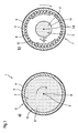
- FIG. 1 shows a spreader roll 1 according to the invention in the non-bent state in cross-section in the region of the bearing 6 (FIG. 1a) in the region of a displacement point 7 (FIG. Figure 1 c).
- the spreader roll 1 has a support core 2 with a longitudinal axis 3.
- the support core 2 is rotatable about its longitudinal axis 3 extending straight.
- the Stauerkem 2 is rotatably supported in the region of its two longitudinal ends 16 via rolling bearings 15.
- the support core 2 is surrounded at least in sections in the direction of its longitudinal axis 3 by an outer jacket 4 with reference 5.
- the outer shell 4 has a longitudinal axis 8 around which it is rotatable.
- the support core 2 is embodied in the present embodiment as a composite body with a foam core 17 and a fiber composite sheath 14 surrounding the foam core.
- the outer jacket is formed in the present embodiment as a hollow body.
- the support core 2 has along its longitudinal axis 3 a changing cross-sectional shape, which tapers on both sides from the section line A-A to the section line B-B.
- the outer jacket 4 is made in one piece from a flexurally elastic fiber composite material in the present embodiment.
- the cover 5 is constructed in the present embodiment of four layers, which are arranged one above the other in the radial direction.
- the first layer is an adhesive layer for bonding the cover 5 to the outer jacket 4
- the second layer is a fiber composite layer
- the third layer is an adhesive layer for bonding the second and fourth layers
- the fourth layer is a ceramic functional layer forming the surface of the cover 5.
- the outer jacket 4 is non-rotatably and non-displaceably connected to the support core 2.
- the rotationally fixed connection is made by an adhesive connection.
- the longitudinal axis 3 of the support core 2 and the longitudinal axis 8 of the outer jacket 4 always fall, i. also in the bent state of the outer shell 4 together. Support core 2 and outer shell 4 are thus rotatable together.
- the outer jacket 4 is supported via a Rolling 9 on a displaceable perpendicular to the longitudinal axis 3 of the Stitzkems 2 bearing 10 from (the arrows in the x and y directions illustrate the possible displacement directions of the bearing 10).
- the outer shell 4 is thus rotatable relative to the bearing 10 and mounted relative to the support core 2 slidably.
- the longitudinal axes 3 and 8 also coincide with the two second support regions 7.
- the bearing 10 can be adjusted in this case via two mutually offset by 90 ° Spindelhubgetriebe in the x and y direction.
- the screw jacks can be driven by stepper motors, which in turn are controlled by an electronic control unit to adjust a variable roll curvature can.
- supporting points 12 pointing in the direction of the support core 2 are arranged on the inner side of the outer jacket 4.
- the bearing 6 is arranged centrally in the longitudinal direction of the outer jacket 4.
- the support regions 12 are arranged on both sides of the bearing 6 in the longitudinal direction of the support core 2.
- the spreader roller is driven by a drive pulley 18 which is in operative connection with a V-belt (not shown).
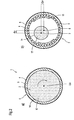
- FIG. 2 shows the spreader roll 1 according to the invention in the bent state in cross-section in the region of the bearing 6 (FIG. 2a, section line AA in FIG. 2c) and in the region of the displacement point 7 (FIG. 2b, section line BB in FIG. 2c) and in FIG Longitudinal section 8 Figure 2c).
- the outer jacket 4 Since in the region of the bearing 6 (FIG. 2 a) the outer jacket 4 is non-rotatably and non-displaceably connected to the support core 2, the relative position between the longitudinal axis 3 and the longitudinal axis 8 does not change in the region of the bearing 6 even in the bent state of the outer jacket 4.
- the longitudinal axis 3 of the Stitzkems 2 and the longitudinal axis 8 of the outer shell 4 coincide in the region of the bearing 6 accordingly.
- the two longitudinal axes 3 and 8 are offset relative to one another by ⁇ x and ⁇ y.
- the outer shell 4 is thus bent and deflected relative to the support core 2 due to the non-displaceable mounting at the bearing 6 and the displacement by .DELTA.x and .DELTA.y at the second support regions 7. Consequently, the longitudinal axis 8 of the outer jacket 4 is curved relative to the longitudinal axis 3 of the support core 2.
- the support points 12 come to the support core 2 to the plant and set the bending line of the outer shell 4 relative to the Stauerkem 2 firmly.
- the support points 12 are displaceable in the circumferential direction of the support core 2 relative to the support core 2.
- a kind of plain bearing of the support core 2 is formed on the outer jacket 4 at the other second support portions 12.
Landscapes
- Rolls And Other Rotary Bodies (AREA)
- Polymers With Sulfur, Phosphorus Or Metals In The Main Chain (AREA)
- Die Bonding (AREA)
- Specific Sealing Or Ventilating Devices For Doors And Windows (AREA)
- Treatment Of Fiber Materials (AREA)
Abstract
Description
Die Erfindung betrifft eine Breitstreckwalze für eine bahnverarbeitende Maschine.The invention relates to a spreader roll for a web-processing machine.
Breitstreckwalzen werden in bahnverarbeitenden Maschinen verwendet, um bei laufenden Materialbahnen eine Faltenbildung oder ein Durchhängen durch Breitstrecken der Materialbahnen zu vermeiden. Des weiteren werden Breitstreckwalzen dazu verwendet, parallel nebeneinander angeordnete Materialbahnen seitlich auseinander laufen zu lassen. Parallel nebeneinander angeordnete Materialbahnen können bspw. durch Längsschneiden einer breiten Materialbahn erzeugt werden.Spreader rolls are used in web-processing machines in order to avoid wrinkling or sagging of the material webs when the webs of material are running. Furthermore, spreader rolls are used to allow side by side juxtaposed material webs to diverge laterally. Parallel juxtaposed webs can be generated, for example, by slitting a wide web of material.
Die aus dem Stand der Technik bekannten Breitstreckwalzen weisen üblicherweise einen gebogenen und stehenden Kern auf, auf weichem mehrere voneinander unabhängige Rollensegmente mittels Rollenlager abgestützt werden um eine gekrümmte Walze in mehreren Abschnitten nachzubilden.The spreader rollers known from the prior art usually have a bent and stationary core on which a plurality of independent roller segments are supported by means of roller bearings in order to simulate a curved roller in several sections.
Die o.g. Breitstreckwalzen sind aufwendig in ihrer Konstruktion und Wartung. Des weiteren ist bei den o.g. Breitstreckwalzen die Krümmung nicht einstellbar.The o.g. Spreader rolls are expensive in their construction and maintenance. Furthermore, the o.g. Spreader rolls the curvature not adjustable.
Aus der
Die
Aus der
Die
Die
Des weiteren werden bei Breitstreckwalzen dieser Art hohe Kräfte auf die Lagerung ausgeübt, was einen hohen Lagerverschleiß zur Folge haben kann.Furthermore, in spreader rolls of this type, high forces are exerted on the bearing, which can result in high bearing wear.
Es ist die Aufgabe der vorliegenden Erfindung ein verbessertes Drehteil, insbesondere eine verbesserte Breitstreckwalze vorzuschlagen.It is the object of the present invention to propose an improved rotary part, in particular an improved spreader roller.
Die Aufgabe wird erfindungsgemäß mit den Merkmalen des Patentanspruchs 1 gelöst.The object is achieved with the features of claim 1.
Vorteilhafte Ausgestaltungen und Weiterbildungen der Erfindung sind in den Unteransprüchen aufgeführt.Advantageous embodiments and further developments of the invention are listed in the subclaims.
Die Erfindung basiert auf der Idee eine Breitstreckwalze zu schaffen, bei welcher der Winkel der Auslenkung wie auch die Größe der Auslenkung (Krümmung) unabhängig vom lagernden Kern vorgenommen werden kann.The invention is based on the idea of creating a spreader roll in which the angle of the deflection as well as the size of the deflection (curvature) can be made independently of the bearing core.
Eine Breitstreckwalze für eine bahnverarbeitende Maschine, gemäß der Gattung weist einen Stützkern mit Längsachse auf. Der Stützkern ist hierbei an seinen beiden längsseitigen Enden gelagert. Des weiteren weist die gattungsgemäße Breitstreckwalze einen elastisch biegbaren Außenmantel auf, der den Stützkern in dessen Umfangrichtung umgibt und der sich zumindest abschnittweise zwischen den beiden längsseitigen Enden des Stützkerns erstreckt.A spreader roll for a web-processing machine, according to the genus has a support core with a longitudinal axis. The support core is mounted here at its two longitudinal ends. Furthermore, the generic spreader roller has an elastically bendable outer jacket, which surrounds the support core in its circumferential direction and which extends at least in sections between the two longitudinal ends of the support core.
Bei der erfindungsgemäßen Breitstreckwalze ist darüber hinaus vorgesehen, dass der Außenmantel am Stützkern an zumindest einem Lager gelagert ist. Hierbei ist der Außenmantel an dem Lager derart gelagert, dass der Außenmantel senkrecht zur Längsachse des Stützkerns unverschiebbar ist. Des weiteren ist der Außenmantel an zumindest einer Verschiebestelle senkrecht zur Längsachse des Stützkerns verschiebbar gelagert, wobei die Verschiebestelle entlang der Längsachse der Stützkerns zum Lager beabstandet ist. Hierdurch ist die Krümmung des Außenmantels einstellbar. Darüber hinaus ist der außenmantel zwischen dem Lager und der Verschiebestelle zumindest abschnittweise elastisch verformbar ausgebildet.In the spreader roll according to the invention, moreover, it is provided that the outer jacket is mounted on the support core on at least one bearing. Here, the outer jacket is mounted on the bearing such that the outer jacket is immovable perpendicular to the longitudinal axis of the support core. Furthermore, the outer jacket is on at least one shift point mounted displaceably perpendicular to the longitudinal axis of the support core, wherein the displacement point is spaced along the longitudinal axis of the support core to the bearing. As a result, the curvature of the outer shell is adjustable. In addition, the outer sheath between the bearing and the displacement point is at least partially elastically deformable.
Dadurch ist es möglich, durch Relativverschiebung von Außenmantel zu Stützkern an der Verschiebestelle den Außenmantel relativ zum Stützkern in eine Position zu bringen, so dass an der Verschiebestelle die Längsachsen von Außenmantel und Stützkern nicht zusammenfallen und am Lager die Längsachsen von Außenmantel und Stützkern zusammenfallen. Um eine Biegung des Außenmantels zwischen der Verschiebestelle und dem Lager zuzulassen, ist der außenmantel zumindest abschnittweise elastisch verformbar ausgebildet.This makes it possible to bring by relative displacement of outer sheath to support core at the displacement of the outer sheath relative to the support core in a position so that the longitudinal axis of the outer sheath and support core do not coincide at the displacement and coincide on the bearing, the longitudinal axes of the outer sheath and support core. In order to allow a bending of the outer shell between the displacement point and the bearing, the outer sheath is formed at least partially elastically deformable.
Im Ergebnis verläuft die Längsachse des Außenmantels zwischen Lager und Verschiebungsstelle relativ zur Längsachse des Stützkerns gekrümmt.As a result, the longitudinal axis of the outer jacket between the bearing and displacement point is curved relative to the longitudinal axis of the support core.
Des weiteren ist bei der erfindungsgemäßen Breitstreckwalze vorgesehen, dass der Stützkern aus einem Schaum- und / oder Honigwabenkern, der zumindest abschnittweise von einem Faserverbundwerkstoff ummantelt ist, aufgebaut ist. Bei der Herstellung des Stützkerns wird hierbei zuerst ein Schaumkern mit nahezu unbegrenzter Möglichkeit der Formgebung geschaffen, der von einem Faserverbundmantel umhüllt wird. Somit entsteht ein Stützkern mit hohem Elastizitätsmodul und geringem Eigengewicht, der einfach und mit nahezu beliebiger Form realisiert werden kann.Furthermore, it is provided in the spreader roll according to the invention, that the support core of a foam and / or honeycomb core, which is at least partially covered by a fiber composite material, constructed. In the production of the support core, a foam core with almost unlimited possibility of shaping is first created, which is enveloped by a fiber composite sheath. This creates a support core with a high modulus of elasticity and low weight, which can be realized easily and with almost any shape.
Unter eine Verschieblichkeit bzw. Unverschieblichkeit senkrecht zur Längsachse des Stützkerns ist in diesem Zusammenhang zu verstehen, dass die Verschiebung eine Komponente hat, die senkrecht zur Längsachse des Stützkerns an der Verschiebestelle bzw. Lager verläuft.Under a displaceability or immobility perpendicular to the longitudinal axis of the support core is to be understood in this context that the displacement of a Component which is perpendicular to the longitudinal axis of the support core at the displacement point or bearing.
Der Außenmantel ist hierbei vorzugsweise zwischen dem Lager und der Verschiebestelle einteilig ausgebildet.The outer jacket is preferably formed integrally between the bearing and the displacement point.
Unter einteilig soll in diesem Zusammenhang verstanden werden, dass der Außenmantel durch einen zusammenhängenden Materialabschnitt (entweder aus einem Guss oder aus mehreren Materialabschnitten zusammengefügt) und nicht durch mehrere nicht miteinander verbundene Materialabschnitte gebildet wird.Unitary is to be understood in this context that the outer shell is formed by a contiguous portion of material (either made of a single cast or of several material sections) and not by a plurality of non-interconnected material sections.
Somit wird eine Breitstreckwalze geschaffen, bei der die aus dem Stand der Technik bekannten Nachteile überwunden sind.Thus, a spreader roller is provided in which the known from the prior art disadvantages are overcome.
Selbstverständlich ist es auch möglich, dass der Außenmantel auch eine Verschiebekomponente parallel zur Längsachse des Stützkerns hat. Dadurch kann der Außenmantel in seiner Längsrichtung gestaucht werden, wodurch eine andere Biegelinie erhalten werden kann.Of course, it is also possible that the outer jacket also has a displacement component parallel to the longitudinal axis of the support core. Thereby, the outer shell can be compressed in its longitudinal direction, whereby a different bending line can be obtained.
Nach einer bevorzugten Ausführungsform der Erfindung sind zwei Verschiebestellen vorgesehen, zwischen denen das Lager angeordnet ist. Dadurch ist es möglich, den Außenmantel beidseitig des lagers zu krümmen.According to a preferred embodiment of the invention, two displacement points are provided, between which the bearing is arranged. This makes it possible to bend the outer sheath on both sides of the camp.
Nach einer bevorzugten Ausführungsform der Erfindung ist vorgesehen, dass der Außenmantel an seinen beiden längsseitigen Enden jeweils eine Verschiebestelle aufweist. Ist das Lager hierbei vorzugsweise im Mittenbereich der Längserstreckung des Außenmantels vorgesehen, kann der Außenmantel relativ zum Lager symmetrisch gebogen werden.According to a preferred embodiment of the invention, it is provided that the outer shell has a respective displacement point at its two longitudinal ends. If the bearing is preferably provided in the middle region of the longitudinal extension of the outer jacket, the outer jacket can be bent symmetrically relative to the bearing.
Nach einer weiteren bevorzugten Ausführungsform ist der Außenmantel am Lager drehbar mit dem Stützkern verbunden, sodass der Außenmantel auf dem Stützkern drehbar gelagert ist. Die drehbare Lagerung kann hierbei über Wälz- oder Gleitlager erfolgen. Als Gleitlager sind bspw. hydrodynamische oder hydrostatische Gleitlager oder Luftlager denkbar.According to a further preferred embodiment of the outer jacket is rotatably connected to the bearing with the support core, so that the outer shell is rotatably mounted on the support core. The rotatable mounting can be done via rolling or plain bearings. As plain bearings are, for example, hydrodynamic or hydrostatic sliding bearings or air bearings conceivable.
Das o.g. Merkmal ist insbesondere, aber nicht ausschließlich von Vorteil, wenn der Stützkern nicht um seine Längsachse drehbar ist.The o.g. Feature is particularly but not exclusively advantageous if the support core is not rotatable about its longitudinal axis.
Nach einer weiteren bevorzugten Ausführungsform ist der Außenmantel an der ersten Abstützstelle drehfest mit dem Stützkern verbunden. Dies bedeutet, dass eine starre Verbindung zwischen Außenmantel und Stützkern geschaffen wird um eine Drehmomentübertragung zwischen Stützkem und Außenmantel zu ermöglichen und den Außenmantel gegenüber dem Stützkem gegen Verschiebung in Längsrichtung zu sichern. Die drehfeste Verbindung zwischen Stützkem und Außenmantel ist bspw. durch Verkleben oder Verpressen herstellbar.According to a further preferred embodiment, the outer sheath is rotatably connected to the support core at the first support point. This means that a rigid connection between outer shell and support core is created around a To allow torque transmission between Stützkem and outer sheath and secure the outer sheath against the Stützkem against displacement in the longitudinal direction. The non-rotatable connection between Stützkem and outer jacket is, for example. By gluing or pressing produced.
Die o.g. Ausführungsform ist im wesentlichen anwendbar, wenn der Stützkem um seine Längsachse drehbar ist.The o.g. Embodiment is essentially applicable when the Stützkem is rotatable about its longitudinal axis.
Eine weitere Ausgestaltung der vorliegenden Erfindung sieht darüber hinaus vor, dass zumindest eine am Außenmantel oder am Stützkem befestigte und in Längsrichtung zwischen Lager und Verschieberstelle angeordnete Abstützstelle vorgesehen ist, an welcher bei Krümmung des Außenmantels der Stützkern oder der Außenmantel zumindest abschnittweise zur Anlage bringbar ist. Durch die zumindest eine Abstützstelle ist es möglich, die Krümmungs- oder Biegelinie des Außenmantels relativ zum Stützkem zu beeinflussen, da durch die Abstützstelle der minimale Abstand zwischen Außenmantel und Stützkem bei Biegung des Außenmantels festgelegt wird. Da bei Drehung des gekrümmten Außenmantels, unabhängig davon ob der Stützkem am Lager drehfest oder drehbar mit dem Außenmantel verbunden ist, im Bereich der zweiten Abstützstellen eine Relativbewegung zwischen Stützkem und Außenmantel hervorgerufen wird, ist es notwendig den Stützkem mit dem Außenmantel hier miteinander drehbar zu verbinden. Die drehbare Lagerung kann hierbei über winkelverstellbare Wälz- oder Gleitlager erfolgen.A further embodiment of the present invention also provides that at least one support point attached to the outer casing or Stützkem and arranged in the longitudinal direction between the bearing and displacement point is provided, on which at least the curvature of the outer shell of the support core or the outer shell can be brought into abutment. By at least one support point, it is possible to influence the curvature or bending line of the outer shell relative to the Stützkem, as determined by the support point, the minimum distance between the outer shell and Stützkem upon bending of the outer shell. Since upon rotation of the curved outer jacket, regardless of whether the Stützkem on the bearing is rotatably or rotatably connected to the outer shell, in the region of the second support points, a relative movement between Stützkem and outer shell is caused, it is necessary the Stützkem with the outer shell here to rotate together , The rotatable mounting can be done via angle-adjustable rolling or plain bearings.
Nach einer weiteren bevorzugten Ausgestaltung der Erfindung ist vorgesehen, dass die zweiten Abstützstellen in Längsrichtung beidseitig vom Lager und zwischen den beiden Verschiebestellen angeordnet sind. Somit ist es möglich eine Krümmung des Außenmantels einzustellen, die symmetrisch zum Lager verläuft. Durch Abstützung des Außenmantels auf einer Vielzahl von Abstützstellen beidseitig des Lagers ist es möglich, die Biegelinie des Außenmantels relativ zum Stützkern sehr genau zu beeinflussen.According to a further preferred embodiment of the invention it is provided that the second support points are arranged in the longitudinal direction on both sides of the bearing and between the two displacement points. Thus, it is possible to set a curvature of the outer shell, which runs symmetrically to the bearing. By supporting the outer shell on a plurality of support points on both sides of the bearing, it is possible to influence the bending line of the outer shell relative to the support core very accurately.
Die Position des Außenmantels relativ zum Stützkem kann bspw. durch zwei gegeneinander verdrehbare Exzenterscheiben, die jweils auf die an den längsseitigen Enden angeordneten Verschiebestellen Einfluss nehmen bewerkstelligt werden. Hierbei wird durch die Auslenkung an den Verschiebestellen und die unverschiebliche Lagerung des Außenmantels am Stützkern am Lager ein Moment induziert, Welches den Außenmantel entsprechend seiner Biegelinie relativ zum Stützkern verformt. Eine weitere Möglichkeit der verschieblichen Lagerung besteht durch in zwei Ebenen verschiebbare Führungen, die jeweils auf die an den längsseitigen Enden angeordneten Verschiebestellen Einfluss nehmen können. Es ist aber auch möglich, die Krümmung durch eine lineare Verschiebung herzustellen und anschließend die gekrümmte Breitstreckwalze um die Längsachse des Stützkems zu schwenken.The position of the outer jacket relative to the Stützkem can be accomplished, for example, by two mutually rotatable eccentric discs, which in each case take effect on the arranged at the longitudinal ends displacement points. In this case, a moment is induced by the deflection at the displacement points and the non-displaceable mounting of the outer shell on the support core, which deforms the outer shell according to its bending line relative to the support core. Another possibility of displaceable storage consists of slidable in two levels guides, which can each influence the arranged on the longitudinal ends sliding points. But it is also possible to produce the curvature by a linear displacement and then to pivot the curved spreader roll about the longitudinal axis of the Stützkems.
Die Bestätigung zur Verstellung kann hydraulisch, pneumatisch, elektrisch oder manuell vorgenommen werden.Confirmation of adjustment can be made hydraulically, pneumatically, electrically or manually.
Nach einer weiteren bevorzugten Ausführungsform der Erfindung wird die relative Verstellung durch im Außenrohr eingearbeitete piezoelektrische Elemente bewerkstelligt. Die eingearbeiteten piezoelektrischen Elemente können bspw. in Form von Piezofasern ausgebildet sein. Durch Anlegen von entsprechenden elektrischen Spannungen dehnen und kontrahieren sich die piezoelektrischen Elemente an unterschiedlichen Stellen des Außenmantels, wodurch sich der Außenmantel biegt.According to a further preferred embodiment of the invention, the relative adjustment is accomplished by incorporated in the outer tube piezoelectric elements. The incorporated piezoelectric elements may be formed, for example, in the form of piezo fibers. By applying corresponding electrical voltages, the piezoelectric elements stretch and contract at different points of the outer jacket, whereby the outer jacket bends.
Es gibt unterschiedliche Möglichkeiten wie der Stützkem ausgebildet sein kann. Nach einer weiteren bevorzugten Weiterbildung der Erfindung verläuft die Längsachse des Stützkerns gerade. Bei einem geraden Stützkem ist es sowohl möglich, dass sich der Stützkern um seine eigene Achse dreht wie auch, dass der Stützkem nicht um seine eigene Achse drehbar ist.There are different ways in which the Stützkem can be formed. According to a further preferred embodiment of the invention, the longitudinal axis of the support core is straight. In a straight Stützkem it is possible that the support core rotates about its own axis as well as that the Stützkem is not rotatable about its own axis.
Eine andere Ausgestaltung der Erfindung sieht ferner vor, dass die Längsachse des Stützkems gekrümmt verläuft. Bei dieser Variante ist es nur möglich, dass der Stützkem sich um seine eigene Achse nicht dreht und dass die Drehbarkeit des Außenmantels durch drehbare Lagerung am Lager verwirklicht wird.Another embodiment of the invention further provides that the longitudinal axis of the Stützkems runs curved. In this variant, it is only possible that the Stützkem does not rotate around its own axis and that the rotation of the Outer jacket is realized by rotatable storage in stock.
Zur Optimierung der Belastbarkeit des Kerns und zur teilweisen Festlegung des Krümmungsverlaufs ist es vorteilhaft, wenn der Stützkern entlang seiner Längsachse eine sich zumindest abschnittweise ändernde Querschnittsform ha, insbesondere zumindest abschnittweise konisch verläuft.To optimize the load capacity of the core and to partially determine the curvature, it is advantageous if the support core along its longitudinal axis at least partially changing cross-sectional shape ha, in particular at least partially conical.
Um Schwingungen der Breitstreckwalze im Betrieb möglichst gering zu halten ist es sinnvoll, wenn die Eigenfrequenz des Stützkerns möglichst hoch ist. Demzufolge müssen Elastizitätsmodul möglichst hoch und Stützkernmasse möglichst gering sein. Versuche haben gezeigt, dass Eigenschwingungen im Betrieb nahezu vollständig unterbunden werden können, wenn der Stützkern zumindest teilweise aus einem Material mit einem Elastizitätsmodul im Bereich von 10 bis 1000GPa, bevorzugt von 50 bis 800GPa, besonders bevorzugt von 100 bis 500GPa und einer Dichte im Bereich von 0,5 bis 3g/cm3, bevorzugt von 1,0 bis 2,0g/cm3, besonders bevorzugt von 1,3 bis 2,0g/cm3 gefertigt ist.In order to keep vibrations of the spreader roller during operation as low as possible, it makes sense if the natural frequency of the support core is as high as possible. Consequently, the modulus of elasticity must be as high as possible and core mass as low as possible. Experiments have shown that natural oscillations in operation can be almost completely suppressed if the support core at least partially made of a material having a modulus of elasticity in the range of 10 to 1000GPa, preferably from 50 to 800GPa, more preferably from 100 to 500GPa and a density in the range of 0.5 to 3 g / cm 3 , preferably from 1.0 to 2.0 g / cm 3 , more preferably from 1.3 to 2.0 g / cm 3 is made.
Bevorzugte Materialien zur Herstellung des Stützkerns sind in Kombination oder allein: Kunststoffe und / oder metallische Werkstoff die in Form von Schäumen und / oder in Form von Honigwaben hergestellt sind.Preferred materials for the production of the support core are in combination or alone: plastics and / or metallic material which are produced in the form of foams and / or in the form of honeycombs.
Nach einer weiteren bevorzugten Ausführungsform hat der Außenmantel in seiner Längsrichtung ein Elastizitätsmodul im Bereich von 0,5 bis 1000GPa, bevorzugt von 10 bis 700GPa, besonders bevorzugt von 50 bis 200GPa, wobei das Elastizitätsmodul des Stützkerns größer als das Elastizitätsmodul des Außenmantels ist. Somit wird ein in Längsrichtung möglichst biegeweicher Außenmantel geschaffen. Das geringere Elastizitätsmodul in Längsrichtung des Stützkerns kann bspw. dadurch erreicht werden, dass bei einem Faserverbundwerkstoff die Fasern im wesentlichen in Umfangrichtung des Stützkerns orientiert sind.According to a further preferred embodiment, the outer shell in its longitudinal direction has a modulus of elasticity in the range from 0.5 to 1000GPa, preferably from 10 to 700GPa, more preferably from 50 to 200GPa, the elastic modulus of the support core being greater than the modulus of elasticity of the outer jacket. Thus, a flexible as possible outer jacket is provided in the longitudinal direction. The lower modulus of elasticity in the longitudinal direction of the support core can be achieved, for example, in that, in the case of a fiber composite material, the fibers are oriented essentially in the circumferential direction of the support core.
Damit der Kreisquerschnitt des Außenmantels bei Bahnzug und Krümmung keine allzu große Abplattung erfährt ist es sinnvoll, wenn der Außenmantel in radialer Richtung möglichst wenig deformierbar ist. Daher sieht eine bevorzugte Ausführungsform der Erfindung vor, dass der Außenmantel in radialer Richtung ein Elastizitätsmodul hat, welches größer als das Elastizitätsmodul in Längsrichtung ist.So that the circular cross-section of the outer jacket does not experience too much flattening in the case of the web tension and the curvature, it makes sense if the outer casing is as little deformable as possible in the radial direction. Therefore, a preferred embodiment of the invention provides that the outer jacket in the radial direction has a modulus of elasticity which is greater than the elastic modulus in the longitudinal direction.
Die Beeinflussung der Biegelinie des Außenmantels kann durch Änderung der Materialdicke des Außenmantels beeinflusst werden, sodass abhängig von den Anforderungen an die Breitstreckwalze unterschiedliche Biegelinien eingestellt werden können. Demzufolge sieht eine bevorzugte Weiterbildung der Erfindung vor, dass der Außenmantel in seiner Längsrichtung eine sich zumindest abschnittweise ändernde Materialdicke und / oder Querschnittsform aufweist. Andere Möglichkeiten zur Beeinflussung der Biegelinie des Außenmantels bestehen durch Materialorientierung und / oder durch die gewählte Materialkombination.The influence of the bending line of the outer shell can be influenced by changing the material thickness of the outer shell, so that different bending lines can be adjusted depending on the requirements of the spreader roll. Accordingly, a preferred development of the invention provides that the outer casing has a material thickness and / or cross-sectional shape which changes at least in sections in its longitudinal direction. Other possibilities for influencing the bending line of the outer shell consist of material orientation and / or by the selected material combination.
Vorzugsweise ist der Außenmantel in Kombination oder allein aus einem Kunststoff und / oder aus einem metallischen Werkstoff und / oder aus einem Faserverbundwerkstoff hergestellt.The outer sheath is preferably produced in combination or solely from a plastic and / or from a metallic material and / or from a fiber composite material.
Des weiteren wird der Außenmantel zumindest abschnittweise von einem Bezug ummantelt.Furthermore, the outer sheath is at least partially covered by a cover.
Hierbei ist d er Bezug in Kombination oder allein aus elastomerem Kunststoff und / oder aus thermoplastischem Kunststoff und / oder aus duroplastischem Kunststoff und / oder aus Keramikmaterial hergestellt.In this case, the cover is produced in combination or solely from elastomeric plastic and / or from thermoplastic material and / or from thermosetting plastic and / or from ceramic material.
Zur Eigenschaftssteuerung des Bezugs ist es vorteilhaft, wenn sich die Zusammensetzung des Bezugsmaterials in axialer Richtung und / oder in Längsrichtung kontinuierlich und / oder diskontinuierlich ändert.For property control of the cover, it is advantageous if the composition of the cover material changes continuously and / or discontinuously in the axial direction and / or in the longitudinal direction.
Unter einem Bezug mit sich kontinuierlich ändernder Materialzusammensetzung ist bspw. ein Bezug zu verstehen, der in radialer und / oder axialer Richtung eine sich kontinuierlich ändernde Materialzusammensetzung aufweist, d.h. ein Bezugsmaterial das keine Grenzflächen in seiner Zusammensetzung aufweist wie dies bspw. bei Bezugsmaterial im Schichtaufbau der Fall ist. Weist das Bezugsmaterial Grenzflächen in seiner Zusammensetzung auf, so spricht man von einer diskontinuierlichen Materialzusammensetzung.By reference to a continuously changing material composition is meant, for example, a reference having in the radial and / or axial direction a continuously changing material composition, i. a reference material which has no interfaces in its composition as is the case, for example, in reference material in the layer structure. If the covering material has boundary surfaces in its composition, this is called a discontinuous material composition.
Beispielhaft sei ein Bezugsmaterial erwähnt, welches seine Zusammensetzung in radialer Richtung von 100% duroplastischem Material kontinuierlich zu 100% elastomerem Material ändert.By way of example, mention may be made of a cover material which continuously changes its composition in the radial direction from 100% thermoset material to 100% elastomeric material.
Beispielhaft sei des weiteren ein Bezugsmaterial erwähnt, welches aus vier Schichten aufgebaut ist, die in radialer Richtung übereinander liegend angeordnet sind. Ebenfalls ist es möglich, einen Aufbau aus einer und / oder mehreren Schichten, bspw. 2,3,5 oder mehr Schichten zu wählen. Hierbei ist die erste Schicht eine Haftschicht zur Verbindung des Bezug mit dem Außenmantel, die zweite Schicht eine Faserverbundschicht, die dritte Schicht eine Haftschicht zur Verbindung der zweiten und der vierten Schicht und die vierte Schicht eine keramische Funktionsschicht.By way of example, a reference material may be mentioned, which is constructed from four layers, which are arranged one above the other in the radial direction. It is also possible to choose a construction of one or more layers, for example 2.3.5 or more layers. Here, the first layer is an adhesive layer for connecting the cover to the outer jacket, the second layer is a fiber composite layer, the third layer is an adhesive layer for bonding the second and fourth layers and the fourth layer is a ceramic functional layer.
In dem obigen Bsp. ist die Faserverbundschicht aus einer Harzkomponente, einer Härterkomponente, eine Faserkomponente und optional aus einer oder mehreren Füllstoffkomponenten aufgebaut. Hierbei kann die Harzkomponente Epoxidharze, Polyurethanharze, Phenol-Formaldehydharze und / oder Cyanatesterharze enthalten. Die Faserkomponente kann allein oder im Gemisch Fasern der folgenden Typen enthalten: Glas, Carbon, Aramid, Bor, Polypropylen, Polyester, PPS PEEK, Keramik und / oder Carbide wie bspw. SiC. Füllstoffkomponenten können Carbide, Metalle oder Oxide enthalten.In the above example, the fiber composite layer is composed of a resin component, a hardener component, a fiber component, and optionally one or more filler components. Here, the resin component epoxy resins, Polyurethane resins, phenol-formaldehyde resins and / or cyanate ester resins. The fiber component may contain, alone or in admixture, fibers of the following types: glass, carbon, aramid, boron, polypropylene, polyester, PPS PEEK, ceramics and / or carbides such as SiC. Filler components may contain carbides, metals or oxides.
Des weiteren ist denkbar, dass sich bspw. bei einem Matrixmaterial das Verhältnis von Harz und Härterkomponente kontinuierlich ändert.Furthermore, it is conceivable that, for example, in the case of a matrix material, the ratio of resin and hardener component changes continuously.
Des weiteren umfasst die obige Ausführungsform, dass sich die Materialzusammensetzung in Längsrichtung des Bezugs kontinuierlich oder diskontinuierlich ändert. Dies ist bspw. dann sinnvoll, wenn Randzonen stärker beansprucht werden. In diesem Fall können dann die Randzonen aus einem verschleißfesteren Material als die anderen Bereiche ausgeführt werden.Further, the above embodiment includes that the material composition changes continuously or discontinuously in the longitudinal direction of the reference. This is useful, for example, when edge zones are subjected to greater stress. In this case, then the edge zones can be made of a more wear-resistant material than the other areas.
Die Oberfläche einer Breitstreckwalze hat entsprechend des jeweiligen Anwendungsfalls unterschiedliche Aufgaben zu erfüllen. Um eine möglichst gute Breitstreckwirkung erzielen zu können, sollte eine möglichst gute Haftung der Materialbahn gewährleistet werden, woraus sich die Anforderung an eine raue Oberfläche des Bezugs ergibt. Um die Verschmutzungsneigung der Oberfläche des Bezugs gering zu halten, sollte die Oberfläche des Bezugs möglichst glatt sein. Versuche haben gezeigt, dass beste Ergebnisse erzielt werden, wenn die Oberfläche des Bezugs eine Rauhigkeit im Bereich zwischen Ra=0,001 bis 100µm, bevorzugt Ra=0,001 bis 50µm, besonders bevorzugt Ra=0,03 bis 20µm aufweist.The surface of a spreader roll has to fulfill different tasks according to the particular application. In order to achieve the best possible spreading effect, the best possible adhesion of the material web should be ensured, which results in the requirement for a rough surface of the cover. To minimize the tendency of the surface of the cover to foul, the surface of the cover should be as smooth as possible. Experiments have shown that best results are achieved when the surface of the cover has a roughness in the range between Ra = 0.001 to 100 μm, preferably Ra = 0.001 to 50 μm, particularly preferably Ra = 0.03 to 20 μm.
Nach einer weiteren bevorzugten Ausführungsform der Erfindung weist die Oberfläche zumindest abschnittweise spiralförmig und / oder radial angeordnete Nuten und / oder durchgehende Bohrungen und / oder Blindbohrungen auf. Durch diese Ausführungsform werden bspw. Nuten zum Abführen von Luft geschaffen. Die durchgehenden Bohrungen können des weiteren besaugt werden.According to a further preferred embodiment of the invention, the surface has at least sections of spirally and / or radially arranged grooves and / or through holes and / or blind holes. By this embodiment, for example, grooves for removing air are created. The through holes can be further evacuated.
Um die Breitstreckwalze anzutreiben ist entweder vorgesehen, dass der Stützkern angetrieben wird und das Drehmoment über das Lager auf den drehfest mit dem Stützkern verbundenen Außenmantel überträgt. Ist der Außenmantel drehbar mit dem Stützkern verbunden, ist es sinnvoll, wenn der Außenmantel direkt durch einen Keilriemen- oder Zahnriemen- oder Ketten- oder Zahnradantrieb angetrieben wird.To drive the spreader roll is either provided that the support core is driven and transmits the torque through the bearing on the non-rotatably connected to the support core outer shell. If the outer casing is rotatably connected to the support core, it makes sense if the outer casing is driven directly by a V-belt or toothed belt or chain or gear drive.
Die Erfindung soll weiter anhand der folgenden schematischen und nicht maßstäblichen Zeichnungen näher erläutert werden. Es zeigen
- Figur 1
- eine erfindungsgemäße Breitstreckwalze im nicht gebogenen Zustand im Querschnitt im Bereich des Lagers und im Bereich einer Abstützstelle sowie im Längsschnitt,
Figur 2- eine erfindungsgemäße Breitstreckwalze im gebogenen Zustand im Querschnitt im Bereich des Lagers und im Bereich einer Abstützstelle sowie im Längsschnitt.
- FIG. 1
- a spreader roll according to the invention in the non-bent state in cross-section in the region of the bearing and in the region of a support point and in longitudinal section,
- FIG. 2
- a spreader roll according to the invention in the bent state in cross section in the region of the bearing and in the region of a support point and in longitudinal section.
Die Figur 1 zeigt eine erfindungsgemäße Breitstreckwalze 1 im nicht gebogenen Zustand im Querschnitt im Bereich des Lagers 6 (Figur 1 a; Schnittlinie A-A in Figur 1c) und im Bereich einer Verschiebestelle 7 (Figur 1b; Schnittlinie B-B in Figur 1b) sowie im Längsschnitt (Figur 1 c).1 shows a spreader roll 1 according to the invention in the non-bent state in cross-section in the region of the bearing 6 (FIG. 1a) in the region of a displacement point 7 (FIG. Figure 1 c).
Die Breitstreckwalze 1 weist einen Stützkern 2 mit Längsachse 3 auf. Der Stützkern 2 ist um seine sich gerade erstreckende Längsachse 3 drehbar. Hierbei ist der Stützkem 2 im Bereich seiner beiden längsseitigen Enden 16 über Wälzlager 15 drehbar gelagert.The spreader roll 1 has a
Der Stützkern 2 wird in Richtung seiner Längsachse 3 von einem Außenmantel 4 mit Bezug 5 zumindest abschnittweise umgeben. Der Außenmantel 4 hat eine Längsachse 8 um welche er drehbar ist.The
Der Stützkern 2 ist im vorliegenden Ausführungsbeispiel als Verbundkörper mit einem Schaumkern 17 und einen den Schaumkern umhüllenden Faserverbundmantel 14 ausgeführt.The
Der Außenmantel ist im vorliegenden Ausführungsbeispiel als Hohlkörper ausgebildet.The outer jacket is formed in the present embodiment as a hollow body.
Wie aus der Figur 1c zu erkennen ist, hat der Stützkem 2 entlang seiner Längsachse 3 eine sich ändernde Querschnittsform, welche sich beidseitig von der Schnittlinie A-A zur Schnittlinie B-B verjüngt.As can be seen from FIG. 1c, the
Der Außenmantel 4 ist im vorliegenden Ausführungsbeispiel einstückig aus einem biegeelastischen Faserverbundwerkstoff hergestellt.The
Der Bezug 5 ist im vorliegenden Ausführungsbeispiel aus vier Schichten aufgebaut, die in radialer Richtung übereinander liegend angeordnet sind. Hierbei ist die erste Schicht eine Haftschicht zur Verbindung des Bezug 5 mit dem Außenmantel 4, die zweite Schicht eine Faserverbundschicht, die dritte Schicht eine Haftschicht zur Verbindung der zweiten und der vierten Schicht und die vierte Schicht eine die Oberfläche des Bezugs 5 bildende keramische Funktionsschicht.The
Im Bereich des Lagers 6 (Figur 1a) ist der Außenmantel 4 drehfest und nicht verschieblich mit dem Stützkern 2 verbunden. Die drehfeste Verbindung wird durch eine Klebeverbindung hergestellt. Im Bereich des Lagers 6 fallen die Längsachse 3 des Stützkems 2 und die Längsachse 8 des Außenmantels 4 immer, d.h. auch im gebogenen Zustand des Außenmantels 4 zusammen. Stützkern 2 und Außenmantel 4 sind somit gemeinsam drehbar.In the region of the bearing 6 (FIG. 1 a), the
Im Bereich der Verschiebestelle 7, die in der Figur 1b im Bereich eines längsseitigen Endes des Außenmantels 4 angeordnet ist, stützt sich der Außenmantel 4 über ein Wälzlager 9 an einer senkrecht zur Längsachse 3 des Stützkems 2 verschieblichen Lagerung 10 ab (die Pfeile in x- und y-Richtung veranschaulichen die möglichen Verschieberichtungen der Lagerung 10). Der Außenmantel 4 ist somit gegenüber der Lagerung 10 drehbar und gegenüber dem Stützkern 2 verschieblich gelagert. Im ungebogenen Zustand des Außenmantels 4 fallen auch bei den beiden zweiten Abstützbereichen 7 die Längsachsen 3 und 8 zusammen.In the region of the
Die Lagerung 10 kann hierbei über zwei um 90° zueinander versetzte Spindelhubgetriebe in x- und y-Richtung verstellt werden. Die Spindelhubgetriebe können hierbei über Schrittmotoren angetrieben werden, die wiederum über eine Steuerelektronik angesteuert werden, um eine variable Walzenkrümmung einstellen zu können.The bearing 10 can be adjusted in this case via two mutually offset by 90 ° Spindelhubgetriebe in the x and y direction. The screw jacks can be driven by stepper motors, which in turn are controlled by an electronic control unit to adjust a variable roll curvature can.
Um die Biegelinie des Außenmantels 4 im gebogenen Zustand entsprechend den Anforderungen beeinflussen zu können, sind an der Innenseite des Außenmantels 4 in Richtung des Stützkems 2 weisende Abstützstellen 12 angeordnet. Die Abstützstellen 12 legen bei gebogenen Außenmantel 4 in Kontakt mit dem Stützkem 2 den minimalen Abstand zwischen Außenmantel 4 und Stützkem 2 fest, wodurch die Biegelinie des Außenmantels 4 festgelegt wird.In order to be able to influence the bending line of the
Das Lager 6 ist in Längserstreckung des Außenmantels 4 mittig angeordnet. Die Abstützbereiche 12 sind in Längsrichtung des Stützkerns 2 beidseitig von dem Lager 6 angeordnet.The
Im vorliegenden Ausführungsbeispiel wird die Breitstreckwalze über eine Antriebsscheibe 18 angetrieben die mit einem Keilriemen (nicht dargestellt) in Wirkverbindung steht.In the present embodiment, the spreader roller is driven by a
Figur 2 zeigt die erfindungsgemäße Breitstreckwalze 1 im gebogenen Zustand im Querschnitt im Bereich des Lagers 6 (Figur 2a, Schnittlinie A-A in Figur 2c) und im Bereich der Verschiebestelle 7 (Figur 2b; Schnittlinie B-B in Figur 2c) sowie im Längsschnitt 8 Figur 2c).FIG. 2 shows the spreader roll 1 according to the invention in the bent state in cross-section in the region of the bearing 6 (FIG. 2a, section line AA in FIG. 2c) and in the region of the displacement point 7 (FIG. 2b, section line BB in FIG. 2c) and in
Da im Bereich des Lagers 6 (Figur 2a) der Außenmantel 4 drehfest und nicht verschieblich mit dem Stützkern 2 verbunden ist, ändert sich im Bereich des Lagers 6 auch im gebogenen Zustand des Außenmantels 4 nicht die relative Position zwischen der Längsachse 3 zur Längsachse 8. Die Längsachse 3 des Stützkems 2 und die Längsachse 8 des Außenmantels 4 fallen im Bereich des Lagers 6 demzufolge zusammen.Since in the region of the bearing 6 (FIG. 2 a) the
Im Bereich der zweiten Abstützstelle 7, sind aufgrund der verschieblichen Lagerung des Außenmantels 4 relativ zum Stützkem 2 die beiden Längsachsen 3 und 8 zueinander um Δx und Δy versetzt. Der Außenmantel 4 ist somit aufgrund der unverschieblichen Lagerung beim Lager 6 und der Verschiebung um Δx und Δy bei den zweiten Abstützbereichen 7 relativ zum Stützkern 2 gebogen und ausgelenkt. Demzufolge ist die Längsachse 8 des Außenmantels 4 relativ zur Längsachse 3 des Stützkerns 2 gekrümmt.In the area of the
In gebogenen Zustand des Außenmantels 4 kommen die Abstützstellen 12 am Stützkern 2 zur Anlage und legen die Biegelinie des Außenmantels 4 relativ zum Stützkem 2 fest. Die Abstützstellen 12 sind in Umfangrichtung des Stützkerns 2 relativ zum Stützkern 2 verschieblich. Somit wird an den weiteren zweiten Abstützbereichen 12 eine Art Gleitlagerung des Stützkerns 2 am Außenmantel 4 gebildet. Um den Gleitwiderstand im Bereich der weiteren zweiten Abstützbereiche 12 zu reduzieren, ist es sinnvoll, wenn der Stützkem 2 an diesen Stellen mit einer Art Gleitbeschichtung versehen ist.In the bent state of the
- 11
- BreitsteckwalzeWide push roller
- 22
- Stützkernsupporting core
- 33
- Längsachse (Stützkern)Longitudinal axis (support core)
- 44
- Außenmantelouter sheath
- 55
- Bezugreference
- 66
- Lagercamp
- 77
- Verschiebestelleshifting point
- 88th
- Längsachse (Außenmantel)Longitudinal axis (outer jacket)
- 99
- Wälzlager (für Außenmantel)Rolling bearings (for outer jacket)
- 1010
- verschiebliche Lagerungmovable storage
- 1111
- Erhebungsurvey
- 1212
- Abstützstellesupport point
- 1313
- längsseitiges Ende (Außenmantel)longitudinal end (outer sheath)
- 1414
- FaserverbundmantelFiber composite shell
- 1515
- Wälzlager (für Stützkern)Rolling bearings (for support core)
- 1616
- längsseitiges Ende (Stützkern)longitudinal end (supporting core)
- 1717
- Schaumkernfoam core
- 1818
- Antriebsscheibesheave
Claims (26)
- Spreader roll (1) for a web-processing machine, having a supporting core (2) with a longitudinal axis (3), which is mounted at its two long ends, and having an elastically flexible outer shell (4), which surrounds the supporting core (2) in its circumferential direction and which, at least in some sections, extends between the two long ends of the supporting core (2), the outer shell (4) being mounted on the supporting core (2) on at least one bearing (6) such that it cannot be displaced, and the outer shell (4) being mounted on at least one displacement point (7) at a distance from the bearing (6) such that it can be displaced in order to permit the curvature of the outer shell (4) to be adjusted at right angles to the longitudinal axis (3) of the supporting core (2), characterized in that the supporting core (2) is constructed from a foam and/or honeycomb core (17) which, at least in some sections, is sheathed in a fibrous composite material (14).
- Spreader roll according to Claim 1, characterized in that two displacement points (7) are provided, between which the bearing (6) is arranged.
- Spreader roll according to Claim 2, characterized in that the outer shell (4) has a displacement point (7) at its two long ends (13) in each case.
- Spreader roll according to one of the preceding claims, characterized in that the outer shell (4) is connected to the supporting core (2) via the bearing (6) such that it can rotate,
- Spreader roll according to one of the preceding claims, characterized in that the supporting core (2) cannot be rotated about its longitudinal axis (3).
- Spreader roll according to one of the preceding Claims 1 to 3, characterized in that the outer shell (4) is connected to the supporting core (2) via the bearing (6) such that it cannot rotate with respect thereto.
- Spreader roll according to Claim 6, characterized in that the supporting core (2) can rotate about its longitudinal axis (3).
- Spreader roll according to one of the preceding claims, characterized in that at least one supporting point (12) is provided, fixed to the outer shell (4)/supporting core (2) and arranged in the longitudinal direction (3) between bearing (6) and displacement point (7), with which, in the event of curvature of the outer shell (4), the supporting core (2)/outer shell (4) can be brought into contact, at least in some sections.
- Spreader roll according to Claim 8, characterized in that the supporting points (12) are arranged on both sides of the bearing (6) in the longitudinal direction (3) of the supporting core (2) and between the two displacement points (7).
- Spreader roll according to one of the preceding claims, characterized in that the relative displacement of the outer shell (4) in relation to the supporting core (2) is brought about by eccentric discs or by guides which can be displaced in two planes and which exert an influence on the displacement points (7).
- Spreader roll according to one of the preceding Claims 1 to 9, characterized in that the relative displacement is brought about by piezoelectric elements incorporated in the outer shell (4).
- Spreader roll according to one of the preceding claims, characterized in that the longitudinal axis (3) of the supporting core (2) runs in a straight line.
- Spreader roll according to one of Claims 1 to 5 and 8 to 11, characterized in that the longitudinal axis (3) of the supporting core (2) runs in a curve.
- Spreader roll according to one of the preceding claims, characterized in that the supporting core (2) has a cross-sectional shape that changes along its longitudinal axis (3), at least in some sections, in particular in that the supporting core (2) runs conically, at least in some sections.
- Spreader roll according to one of the preceding claims, characterized in that the supporting core (2) consists of material with a modulus of elasticity in the range from 10 to 1000 GPa, preferably from 50 to 800 GPa, particularly preferably from 100 to 500 GPa, and with a density in the range from 0.5 to 3 g/cm3, preferably from 1.0 to 2.0 g/cm3, particularly preferably from 1.3 to 2.0 g/cm3.
- Spreader roll according to one of the preceding claims, characterized in that the supporting core (2) is produced in combination or on its own from plastic and/or from a metallic material in the form of foams and/or honeycombs.
- Spreader roll according to one of the preceding claims, characterized in that, in its longitudinal direction, the outer shell (4) has a modulus of elasticity in the range from 0.5 to 1000 GPa, preferably from 10 to 700 GPa, particularly preferably from 50 to 200 GPa.
- Spreader roll according to one of the preceding claims, characterized in that, in the radial direction, the outer shell (4) has a modulus of elasticity which is greater than the modulus of elasticity in the longitudinal direction.
- Spreader roll according to one of the preceding claims, characterized in that, in its longitudinal direction (3), the outer shell (4) has a material thickness and/or cross-sectional shape which changes, at least in some sections.
- Spreader roll according to one of the preceding claims, characterized in that the outer shell (4) is produced in combination or on its own from plastic and/or from a metallic material and/or from a fibrous composite material.
- Spreader roll according to one of the preceding claims, characterized in that the outer shell (4) is sheathed in a cover (5), at least in some sections.
- Spreader roll according to Claim 21, characterized in that the cover (5) is produced in combination or on its own from elastomeric plastic and/or from thermoplastic and/or from thermosetting plastic and/or from ceramic material.
- Spreader roll according to Claim 22, characterized in that the composition of the material from which the cover (5) is produced is continuous in the axial direction and/or in the longitudinal direction (3) and/or changes discontinuously.
- Spreader roll according to either of Claims 21 and 22, characterized in that the surface of the cover (5) has a roughness in the range between Ra = 0.001 to 100 µm, preferably Ra = 0.01 to 50 µm, particularly preferably Ra = 0.03 to 20 µm.
- Spreader roll according to one of Claims 21 to 23, characterized in that, at least in some sections, the surface has grooves arranged spirally and/or radially and/or continuous drilled holes and/or blind drilled holes.
- Spreader roll according to one of Claims 21 to 23, characterized in that the outer shell is evacuated, at least in some sections.
Applications Claiming Priority (2)
| Application Number | Priority Date | Filing Date | Title |
|---|---|---|---|
| DE102004026535A DE102004026535A1 (en) | 2004-05-29 | 2004-05-29 | turned part |
| PCT/EP2005/051812 WO2005115894A1 (en) | 2004-05-29 | 2005-04-22 | Rotary part |
Publications (2)
| Publication Number | Publication Date |
|---|---|
| EP1753682A1 EP1753682A1 (en) | 2007-02-21 |
| EP1753682B1 true EP1753682B1 (en) | 2007-12-19 |
Family
ID=34966851
Family Applications (1)
| Application Number | Title | Priority Date | Filing Date |
|---|---|---|---|
| EP05740020A Expired - Lifetime EP1753682B1 (en) | 2004-05-29 | 2005-04-22 | Spreader roll |
Country Status (5)
| Country | Link |
|---|---|
| US (1) | US7789818B2 (en) |
| EP (1) | EP1753682B1 (en) |
| AT (1) | ATE381509T1 (en) |
| DE (3) | DE202004021651U1 (en) |
| WO (1) | WO2005115894A1 (en) |
Cited By (1)
| Publication number | Priority date | Publication date | Assignee | Title |
|---|---|---|---|---|
| DE102011086986A1 (en) | 2011-11-23 | 2013-05-23 | Voith Patent Gmbh | Spreader roll |
Families Citing this family (14)
| Publication number | Priority date | Publication date | Assignee | Title |
|---|---|---|---|---|
| DE102005044956A1 (en) * | 2005-09-20 | 2007-03-22 | Voith Patent Gmbh | Spreader roll |
| DE102005046812A1 (en) * | 2005-09-30 | 2007-04-05 | Voith Patent Gmbh | Band for transferring a fibrous web to be produced |
| DE102006035776B4 (en) * | 2006-02-01 | 2010-06-17 | GÖRGENS, Detlef | Thread overfeed roller for textile machines |
| EP1967474B1 (en) | 2007-03-07 | 2010-02-17 | Huyck Italia S.p.A | Web spreader roll |
| DE102007016451A1 (en) * | 2007-03-30 | 2008-10-02 | Wilhelm Aichele | A rotary knife |
| DE102007023393A1 (en) | 2007-05-18 | 2008-11-20 | Voith Patent Gmbh | Press arrangement |
| DE102007000847A1 (en) | 2007-10-11 | 2009-04-16 | Voith Patent Gmbh | Pressing arrangement for dewatering web of paper, cardboard, tissue or another type of fibrous web in machine for producing or converting same, comprises press gap through which fibrous web is guided with water-absorbent dewatering belt |
| US8206277B2 (en) * | 2008-04-30 | 2012-06-26 | Hewlett-Packard Development Company, L.P. | Idler roller assembly having a roller and a shaft the roller being formed such that it remains parallel to contacted media despite deflection of the shaft |
| DE102009048074A1 (en) * | 2009-10-01 | 2011-04-07 | Brückner Maschinenbau GmbH & Co. KG | Forging rollers i.e. embossed forging rollers, for use in e.g. short gap or long gap stretching unit, utilized during plastic foil production, have central axle line and/or bending line adjustable to adjust degree of deflection of axle line |
| DE102010029431A1 (en) * | 2010-05-28 | 2011-12-01 | Voith Patent Gmbh | Center-supported roller |
| DE102010026370A1 (en) * | 2010-07-07 | 2012-01-12 | Karl Genthe | Stretching roller for thin web-shaped materials |
| JP6148418B1 (en) * | 2016-02-24 | 2017-06-14 | 日本タングステン株式会社 | Roll for rotary cutter and rotary cutter |
| DE102022118390A1 (en) * | 2022-07-22 | 2024-01-25 | Manroland Goss Web Systems Gmbh | Additively manufactured guide roller |
| EP4467492A1 (en) * | 2023-05-24 | 2024-11-27 | Armor | Compliant system with fin |
Family Cites Families (25)
| Publication number | Priority date | Publication date | Assignee | Title |
|---|---|---|---|---|
| US242058A (en) * | 1881-05-24 | sohtjrmann | ||
| US1609377A (en) * | 1922-01-19 | 1926-12-07 | Paper & Textile Machinery Comp | Roll construction |
| US2676387A (en) * | 1951-07-11 | 1954-04-27 | Downingtown Mfg Co | Mounting for smoothing press rolls |
| US3161125A (en) * | 1961-02-15 | 1964-12-15 | Beloit Iron Works | Adjustable crown roll |
| SE341660B (en) * | 1969-03-07 | 1972-01-10 | L Bjoerkegren | |
| DE2042001A1 (en) * | 1970-08-25 | 1972-04-27 | Kleinewefers Ind Co Gmbh | Guide roll on calenders |
| US3662446A (en) * | 1971-02-25 | 1972-05-16 | Mccreary Ind Products Co | Lightweight roll construction |
| US3750246A (en) * | 1971-09-13 | 1973-08-07 | Gulf & Western Syst Co | Composite roll |
| CH577643A5 (en) * | 1974-05-08 | 1976-07-15 | Escher Wyss Ag | |
| US4158128A (en) * | 1977-06-20 | 1979-06-12 | Ivanovsky Nauchno-Issledo-Valetelsky Experimentalnokonstruktorsky Mashinostroitelny Institut | Roller for applying uniform load across the width of processed sheet material |
| US4305191A (en) * | 1978-05-31 | 1981-12-15 | Shozo Enomoto | Squeeze roll adapted to adjust widthwise distribution of pressure on cloth being treated |
| US4253392A (en) * | 1979-04-09 | 1981-03-03 | International Business Machines Corporation | Hollow fuser roll with variable taper |
| CH648238A5 (en) * | 1979-10-09 | 1985-03-15 | Roland Man Druckmasch | DEVICE FOR BOWING A PRINT ROLL OF A ROTATION PRINTING MACHINE. |
| FI60430C (en) * | 1980-04-24 | 1982-01-11 | Waertsilae Oy Ab | BOEJNINGSKOMPENSERING I VALS |
| FI67675C (en) * | 1980-09-04 | 1985-05-10 | Frankenthal Ag Albert | CYLINDER FOR BANFORM MATERIAL BEARBETANDE MASKINER |
| US4487122A (en) * | 1983-11-04 | 1984-12-11 | Gravure Research Institute, Inc. | Deflection compensating roll for providing uniform contact pressure |
| DE3700596A1 (en) * | 1987-01-10 | 1988-07-28 | Fleissner Maschf Ag | Bend-compensating roll |
| US4813258A (en) * | 1987-01-14 | 1989-03-21 | United Engineering, Inc. | Assembled flexible edge roll |
| JP2809975B2 (en) * | 1993-09-21 | 1998-10-15 | 日立金属株式会社 | Magnet roll and developing roll using the same |
| DE19626565A1 (en) * | 1996-07-03 | 1998-01-08 | Schloemann Siemag Ag | Roll stand for rolling rolled strips |
| US6409645B1 (en) * | 1997-06-13 | 2002-06-25 | Sw Paper Inc. | Roll cover |
| FI103071B1 (en) | 1997-08-19 | 1999-04-15 | Valmet Corp | Bendable roller for web material |
| DE19940424A1 (en) * | 1999-08-26 | 2001-03-01 | Voith Paper Patent Gmbh | Roller with a rotating mantle tube around a fixed core has setting units and bearings to adjust and maintain the radial gap between the mantle and core in a controlled bending action |
| DE20005499U1 (en) * | 2000-03-23 | 2000-08-10 | Suchy, Wolfgang, 07545 Gera | Deflection correction arrangement for squeeze rollers |
| DE10112202A1 (en) * | 2001-03-09 | 2002-09-19 | Voith Paper Patent Gmbh | roller |
-
2004
- 2004-05-29 DE DE202004021651U patent/DE202004021651U1/en not_active Expired - Lifetime
- 2004-05-29 DE DE102004026535A patent/DE102004026535A1/en not_active Withdrawn
-
2005
- 2005-04-22 WO PCT/EP2005/051812 patent/WO2005115894A1/en not_active Ceased
- 2005-04-22 EP EP05740020A patent/EP1753682B1/en not_active Expired - Lifetime
- 2005-04-22 DE DE502005002301T patent/DE502005002301D1/en not_active Expired - Lifetime
- 2005-04-22 AT AT05740020T patent/ATE381509T1/en active
-
2006
- 2006-11-28 US US11/564,036 patent/US7789818B2/en not_active Expired - Fee Related
Cited By (1)
| Publication number | Priority date | Publication date | Assignee | Title |
|---|---|---|---|---|
| DE102011086986A1 (en) | 2011-11-23 | 2013-05-23 | Voith Patent Gmbh | Spreader roll |
Also Published As
| Publication number | Publication date |
|---|---|
| US20080205867A1 (en) | 2008-08-28 |
| DE502005002301D1 (en) | 2008-01-31 |
| EP1753682A1 (en) | 2007-02-21 |
| US7789818B2 (en) | 2010-09-07 |
| DE102004026535A1 (en) | 2005-12-22 |
| ATE381509T1 (en) | 2008-01-15 |
| WO2005115894A1 (en) | 2005-12-08 |
| DE202004021651U1 (en) | 2009-10-08 |
Similar Documents
| Publication | Publication Date | Title |
|---|---|---|
| EP1753682B1 (en) | Spreader roll | |
| DE10011464C1 (en) | Storage of an adjustable rotor blade of a wind turbine | |
| EP2489888B1 (en) | Accurately fitted plain bearing | |
| EP0614024B1 (en) | Actuator for a disc brake | |
| DE102008025414B4 (en) | Aerodynamic profile with reversible deformable contour for aircraft, in particular for rotary-wing aircraft | |
| CH653105A5 (en) | VIBRATION DAMPED BEARING DEVICE. | |
| EP2210005A1 (en) | Axial bearing, particularly for a turbocharger | |
| DE69838504T2 (en) | BENDABLE ROLL FOR BANDED MATERIAL | |
| DE19927897A1 (en) | Contact- or conveyor roller for plastic or paper with adjustable flexure to counter or induce bending, comprises unitary or composite, continuous outer casing material | |
| DE102005044956A1 (en) | Spreader roll | |
| DE102006049290B4 (en) | Roller with adjustable bend | |
| EP1186387A2 (en) | Rotary cutting press | |
| DE102017112924B4 (en) | planetary gear | |
| DE10049548B4 (en) | Electric power steering device | |
| CH681863A5 (en) | ||
| EP1114890A2 (en) | Roll arrangement and roll | |
| EP1749926B1 (en) | Pressing arrangement | |
| EP1686274B1 (en) | Bearing | |
| EP1228993B1 (en) | Roller for winding a material web | |
| EP1988212B1 (en) | Roll bending assembly | |
| DE29602948U1 (en) | Device for regulating the deflection of a rotating body | |
| WO2008037515A1 (en) | Roller mill or roll mill | |
| EP1518674B1 (en) | Inking or damping roller of a printing machine | |
| EP4581206B1 (en) | Roll and press apparatus | |
| DE10125381A1 (en) | Bearing block for connecting slide which moves along rail with component to be transported comprises upper and lower sections connected by rod which fits into transverse bore with diverging ends |
Legal Events
| Date | Code | Title | Description |
|---|---|---|---|
| PUAI | Public reference made under article 153(3) epc to a published international application that has entered the european phase |
Free format text: ORIGINAL CODE: 0009012 |
|
| 17P | Request for examination filed |
Effective date: 20061229 |
|
| AK | Designated contracting states |
Kind code of ref document: A1 Designated state(s): AT BE BG CH CY CZ DE DK EE ES FI FR GB GR HU IE IS IT LI LT LU MC NL PL PT RO SE SI SK TR |
|
| 17Q | First examination report despatched |
Effective date: 20070330 |
|
| GRAP | Despatch of communication of intention to grant a patent |
Free format text: ORIGINAL CODE: EPIDOSNIGR1 |
|
| RTI1 | Title (correction) |
Free format text: SPREADER ROLL |
|
| DAX | Request for extension of the european patent (deleted) | ||
| GRAS | Grant fee paid |
Free format text: ORIGINAL CODE: EPIDOSNIGR3 |
|
| GRAA | (expected) grant |
Free format text: ORIGINAL CODE: 0009210 |
|
| AK | Designated contracting states |
Kind code of ref document: B1 Designated state(s): AT BE BG CH CY CZ DE DK EE ES FI FR GB GR HU IE IS IT LI LT LU MC NL PL PT RO SE SI SK TR |
|
| REG | Reference to a national code |
Ref country code: GB Ref legal event code: FG4D Free format text: NOT ENGLISH |
|
| REG | Reference to a national code |
Ref country code: IE Ref legal event code: FG4D Free format text: LANGUAGE OF EP DOCUMENT: GERMAN |
|
| REG | Reference to a national code |
Ref country code: CH Ref legal event code: EP |
|
| REF | Corresponds to: |
Ref document number: 502005002301 Country of ref document: DE Date of ref document: 20080131 Kind code of ref document: P |
|
| REG | Reference to a national code |
Ref country code: SE Ref legal event code: TRGR |
|
| PG25 | Lapsed in a contracting state [announced via postgrant information from national office to epo] |
Ref country code: LT Free format text: LAPSE BECAUSE OF FAILURE TO SUBMIT A TRANSLATION OF THE DESCRIPTION OR TO PAY THE FEE WITHIN THE PRESCRIBED TIME-LIMIT Effective date: 20071219 Ref country code: NL Free format text: LAPSE BECAUSE OF FAILURE TO SUBMIT A TRANSLATION OF THE DESCRIPTION OR TO PAY THE FEE WITHIN THE PRESCRIBED TIME-LIMIT Effective date: 20071219 Ref country code: SI Free format text: LAPSE BECAUSE OF FAILURE TO SUBMIT A TRANSLATION OF THE DESCRIPTION OR TO PAY THE FEE WITHIN THE PRESCRIBED TIME-LIMIT Effective date: 20071219 Ref country code: PL Free format text: LAPSE BECAUSE OF FAILURE TO SUBMIT A TRANSLATION OF THE DESCRIPTION OR TO PAY THE FEE WITHIN THE PRESCRIBED TIME-LIMIT Effective date: 20071219 |
|
| NLV1 | Nl: lapsed or annulled due to failure to fulfill the requirements of art. 29p and 29m of the patents act | ||
| GBV | Gb: ep patent (uk) treated as always having been void in accordance with gb section 77(7)/1977 [no translation filed] | ||
| PG25 | Lapsed in a contracting state [announced via postgrant information from national office to epo] |
Ref country code: CZ Free format text: LAPSE BECAUSE OF FAILURE TO SUBMIT A TRANSLATION OF THE DESCRIPTION OR TO PAY THE FEE WITHIN THE PRESCRIBED TIME-LIMIT Effective date: 20071219 Ref country code: IS Free format text: LAPSE BECAUSE OF FAILURE TO SUBMIT A TRANSLATION OF THE DESCRIPTION OR TO PAY THE FEE WITHIN THE PRESCRIBED TIME-LIMIT Effective date: 20080419 Ref country code: ES Free format text: LAPSE BECAUSE OF FAILURE TO SUBMIT A TRANSLATION OF THE DESCRIPTION OR TO PAY THE FEE WITHIN THE PRESCRIBED TIME-LIMIT Effective date: 20080330 |
|
| PG25 | Lapsed in a contracting state [announced via postgrant information from national office to epo] |
Ref country code: SK Free format text: LAPSE BECAUSE OF FAILURE TO SUBMIT A TRANSLATION OF THE DESCRIPTION OR TO PAY THE FEE WITHIN THE PRESCRIBED TIME-LIMIT Effective date: 20071219 Ref country code: RO Free format text: LAPSE BECAUSE OF FAILURE TO SUBMIT A TRANSLATION OF THE DESCRIPTION OR TO PAY THE FEE WITHIN THE PRESCRIBED TIME-LIMIT Effective date: 20071219 |
|
| PG25 | Lapsed in a contracting state [announced via postgrant information from national office to epo] |
Ref country code: PT Free format text: LAPSE BECAUSE OF FAILURE TO SUBMIT A TRANSLATION OF THE DESCRIPTION OR TO PAY THE FEE WITHIN THE PRESCRIBED TIME-LIMIT Effective date: 20080519 |
|
| REG | Reference to a national code |
Ref country code: IE Ref legal event code: FD4D |
|
| EN | Fr: translation not filed | ||
| PLBE | No opposition filed within time limit |
Free format text: ORIGINAL CODE: 0009261 |
|
| STAA | Information on the status of an ep patent application or granted ep patent |
Free format text: STATUS: NO OPPOSITION FILED WITHIN TIME LIMIT |
|
| BERE | Be: lapsed |
Owner name: VOITH PATENT G.M.B.H. Effective date: 20080430 |
|
| PG25 | Lapsed in a contracting state [announced via postgrant information from national office to epo] |
Ref country code: IE Free format text: LAPSE BECAUSE OF FAILURE TO SUBMIT A TRANSLATION OF THE DESCRIPTION OR TO PAY THE FEE WITHIN THE PRESCRIBED TIME-LIMIT Effective date: 20071219 Ref country code: DK Free format text: LAPSE BECAUSE OF FAILURE TO SUBMIT A TRANSLATION OF THE DESCRIPTION OR TO PAY THE FEE WITHIN THE PRESCRIBED TIME-LIMIT Effective date: 20071219 |
|
| 26N | No opposition filed |
Effective date: 20080922 |
|
| PG25 | Lapsed in a contracting state [announced via postgrant information from national office to epo] |
Ref country code: GB Free format text: LAPSE BECAUSE OF FAILURE TO SUBMIT A TRANSLATION OF THE DESCRIPTION OR TO PAY THE FEE WITHIN THE PRESCRIBED TIME-LIMIT Effective date: 20071219 Ref country code: MC Free format text: LAPSE BECAUSE OF NON-PAYMENT OF DUE FEES Effective date: 20080430 |
|
| PG25 | Lapsed in a contracting state [announced via postgrant information from national office to epo] |
Ref country code: GR Free format text: LAPSE BECAUSE OF FAILURE TO SUBMIT A TRANSLATION OF THE DESCRIPTION OR TO PAY THE FEE WITHIN THE PRESCRIBED TIME-LIMIT Effective date: 20080320 Ref country code: EE Free format text: LAPSE BECAUSE OF FAILURE TO SUBMIT A TRANSLATION OF THE DESCRIPTION OR TO PAY THE FEE WITHIN THE PRESCRIBED TIME-LIMIT Effective date: 20071219 |
|
| PG25 | Lapsed in a contracting state [announced via postgrant information from national office to epo] |
Ref country code: BE Free format text: LAPSE BECAUSE OF NON-PAYMENT OF DUE FEES Effective date: 20080430 |
|
| PG25 | Lapsed in a contracting state [announced via postgrant information from national office to epo] |
Ref country code: BG Free format text: LAPSE BECAUSE OF FAILURE TO SUBMIT A TRANSLATION OF THE DESCRIPTION OR TO PAY THE FEE WITHIN THE PRESCRIBED TIME-LIMIT Effective date: 20080319 Ref country code: FR Free format text: LAPSE BECAUSE OF FAILURE TO SUBMIT A TRANSLATION OF THE DESCRIPTION OR TO PAY THE FEE WITHIN THE PRESCRIBED TIME-LIMIT Effective date: 20081010 |
|
| PG25 | Lapsed in a contracting state [announced via postgrant information from national office to epo] |
Ref country code: CY Free format text: LAPSE BECAUSE OF FAILURE TO SUBMIT A TRANSLATION OF THE DESCRIPTION OR TO PAY THE FEE WITHIN THE PRESCRIBED TIME-LIMIT Effective date: 20071219 |
|
| REG | Reference to a national code |
Ref country code: CH Ref legal event code: PL |
|
| PG25 | Lapsed in a contracting state [announced via postgrant information from national office to epo] |
Ref country code: LI Free format text: LAPSE BECAUSE OF NON-PAYMENT OF DUE FEES Effective date: 20090430 Ref country code: CH Free format text: LAPSE BECAUSE OF NON-PAYMENT OF DUE FEES Effective date: 20090430 |
|
| PG25 | Lapsed in a contracting state [announced via postgrant information from national office to epo] |
Ref country code: LU Free format text: LAPSE BECAUSE OF NON-PAYMENT OF DUE FEES Effective date: 20080422 Ref country code: HU Free format text: LAPSE BECAUSE OF FAILURE TO SUBMIT A TRANSLATION OF THE DESCRIPTION OR TO PAY THE FEE WITHIN THE PRESCRIBED TIME-LIMIT Effective date: 20080620 |
|
| PG25 | Lapsed in a contracting state [announced via postgrant information from national office to epo] |
Ref country code: TR Free format text: LAPSE BECAUSE OF FAILURE TO SUBMIT A TRANSLATION OF THE DESCRIPTION OR TO PAY THE FEE WITHIN THE PRESCRIBED TIME-LIMIT Effective date: 20071219 |
|
| PGFP | Annual fee paid to national office [announced via postgrant information from national office to epo] |
Ref country code: AT Payment date: 20120411 Year of fee payment: 8 |
|
| PGFP | Annual fee paid to national office [announced via postgrant information from national office to epo] |
Ref country code: SE Payment date: 20130418 Year of fee payment: 9 Ref country code: DE Payment date: 20130419 Year of fee payment: 9 |
|
| PGFP | Annual fee paid to national office [announced via postgrant information from national office to epo] |
Ref country code: FI Payment date: 20130411 Year of fee payment: 9 Ref country code: IT Payment date: 20130422 Year of fee payment: 9 |
|
| REG | Reference to a national code |
Ref country code: DE Ref legal event code: R119 Ref document number: 502005002301 Country of ref document: DE |
|
| REG | Reference to a national code |
Ref country code: SE Ref legal event code: EUG |
|
| REG | Reference to a national code |
Ref country code: AT Ref legal event code: MM01 Ref document number: 381509 Country of ref document: AT Kind code of ref document: T Effective date: 20140422 |
|
| REG | Reference to a national code |
Ref country code: DE Ref legal event code: R119 Ref document number: 502005002301 Country of ref document: DE Effective date: 20141101 |
|
| PG25 | Lapsed in a contracting state [announced via postgrant information from national office to epo] |
Ref country code: DE Free format text: LAPSE BECAUSE OF NON-PAYMENT OF DUE FEES Effective date: 20141101 Ref country code: FI Free format text: LAPSE BECAUSE OF NON-PAYMENT OF DUE FEES Effective date: 20140422 Ref country code: SE Free format text: LAPSE BECAUSE OF NON-PAYMENT OF DUE FEES Effective date: 20140423 |
|
| PG25 | Lapsed in a contracting state [announced via postgrant information from national office to epo] |
Ref country code: AT Free format text: LAPSE BECAUSE OF NON-PAYMENT OF DUE FEES Effective date: 20140422 |
|
| PG25 | Lapsed in a contracting state [announced via postgrant information from national office to epo] |
Ref country code: IT Free format text: LAPSE BECAUSE OF NON-PAYMENT OF DUE FEES Effective date: 20140422 |