EP1753677B1 - Abfallbeseitigungsbehälter - Google Patents
Abfallbeseitigungsbehälter Download PDFInfo
- Publication number
- EP1753677B1 EP1753677B1 EP05747520.4A EP05747520A EP1753677B1 EP 1753677 B1 EP1753677 B1 EP 1753677B1 EP 05747520 A EP05747520 A EP 05747520A EP 1753677 B1 EP1753677 B1 EP 1753677B1
- Authority
- EP
- European Patent Office
- Prior art keywords
- receptacle
- lid
- aperture
- base
- support means
- Prior art date
- Legal status (The legal status is an assumption and is not a legal conclusion. Google has not performed a legal analysis and makes no representation as to the accuracy of the status listed.)
- Expired - Lifetime
Links
Images

Classifications
-
- B—PERFORMING OPERATIONS; TRANSPORTING
- B65—CONVEYING; PACKING; STORING; HANDLING THIN OR FILAMENTARY MATERIAL
- B65F—GATHERING OR REMOVAL OF DOMESTIC OR LIKE REFUSE
- B65F1/00—Refuse receptacles; Accessories therefor
- B65F1/14—Other constructional features; Accessories
- B65F1/16—Lids or covers
- B65F1/1607—Lids or covers with filling openings
-
- B—PERFORMING OPERATIONS; TRANSPORTING
- B65—CONVEYING; PACKING; STORING; HANDLING THIN OR FILAMENTARY MATERIAL
- B65F—GATHERING OR REMOVAL OF DOMESTIC OR LIKE REFUSE
- B65F1/00—Refuse receptacles; Accessories therefor
- B65F1/10—Refuse receptacles; Accessories therefor with refuse filling means, e.g. air-locks
-
- B—PERFORMING OPERATIONS; TRANSPORTING
- B65—CONVEYING; PACKING; STORING; HANDLING THIN OR FILAMENTARY MATERIAL
- B65F—GATHERING OR REMOVAL OF DOMESTIC OR LIKE REFUSE
- B65F1/00—Refuse receptacles; Accessories therefor
- B65F1/14—Other constructional features; Accessories
- B65F1/141—Supports, racks, stands, posts or the like for holding refuse receptacles
-
- B—PERFORMING OPERATIONS; TRANSPORTING
- B65—CONVEYING; PACKING; STORING; HANDLING THIN OR FILAMENTARY MATERIAL
- B65F—GATHERING OR REMOVAL OF DOMESTIC OR LIKE REFUSE
- B65F1/00—Refuse receptacles; Accessories therefor
- B65F1/14—Other constructional features; Accessories
- B65F1/16—Lids or covers
- B65F1/1623—Lids or covers with means for assisting the opening or closing thereof, e.g. springs
Definitions
- the present invention relates to a waste disposal receptacle according to the preamble of claim 1 and known from US-A-5 082 132 , for the disposal of rubbish or sanitary waste.
- waste disposal receptacles are available, particularly receptacles that are designed for the disposal of women's sanitary products. Such bins are not generally emptied on site, but are taken away and replaced with a fresh bin, due to the hazardous nature of the waste.
- Sanitary bins are usually accessed via a flap which allows waste material to be placed into the receptacle. This requires that the user handles the bin around the area of access to the bin to expose the flap. This can also accumulate waste material in an area around the access to the receptacle which can be unsightly, and potentially a health hazard.
- EP 0853051 discloses a container for dispensing material held within it. It has an outer casing and a lid that can be slid in and out of the casing to reveal a slit that is large enough for the contents of the container to be removed through it.
- GB 2165530 discloses a child resistant closure device for a container.
- the closure device when unlocked, can be lifted to allow the contents of the container to be dispensed through an opening in the closure.
- US 5082132 discloses a sanitary waste bin having two symmetrically arranged barrels disposed immediately on each side of a main container.
- the barrels are covered with lids and an opening is provided in each barrel that appears to be closed when the barrels are covered with the lids.
- the lids can be lifted to open the openings.
- a waste disposal receptacle as defined in independent claim 1;
- the receptacle includes a body and a lid; wherein the body is defined by a base, a side and an open top; and the lid is defined by a side, a top and an open base and includes an aperture in the side through which material can be deposited into the receptacle; the material when placed into the receptacle via the aperture falls through the open base of the lid and into the body; wherein the body and lid are cylindrical.
- the interaction between the lid side and the body side forms a substantially airtight seal
- the side of the lid is adapted to be received within the body and is reversibly and telescopically movable between an open and closed position such that when the lid is in the closed position the aperture is covered by said body side and when the lid is in the open position, the aperture is exposed;
- the lid is rotatable on the base to at least a limited extent; and, wherein the body includes a retention mechanism which prevents the lid from being readily removed from within the body.
- the receptacle includes an opening means to assist a user in moving the lid from the closed to the open position.
- the opening means is a handle attached to the lid.
- the lid includes a lip which prevents the top of the lid from moving past the open top of the body.
- the body further includes an external support flange.
- the base of the body includes a domed or flat external surface.
- the flat external surface is adapted to support the receptacle in a free standing manner.
- the lid includes fastening means attached to the inside of the lid wall, the fastening means being adapted to allow attachment of freshness products inside the receptacle.
- the lid includes a lip situated above the aperture, the lip being adapted, when the receptacle is in the closed position, to abut the top of the body wall and to allow the aperture to be covered by the body wall.
- the lip is circumferential about the lid side.
- the lip is not circumferential but extends sufficiently about the lid side to extend at least the length of the aperture.
- a receptacle is provided together with a support means, wherein the receptacle further includes an external support flange, and the support means is adapted to interact with the external support flange to removably attach the receptacle to the support means.
- the support means is also attachable to a mounting surface.
- the mounting surface is a wall.
- the support means is a pedestal.
- the invention in broad terms, provides a waste disposal receptacle for containing waste material.
- the receptacle may be especially suitable for use in rest rooms for the disposal of sanitary waste.
- the receptacle may also be used for the disposal of other types of rubbish including food scraps or other perishable wastes.
- the receptacle is adapted to be able to receive waste material with a reduced amount of contact between the user and the access to the receptacle, and is also adapted to be removed as a complete unit for later disposal of the waste material contained therein.
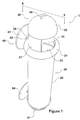
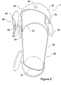
- a receptacle 1 is made up of a body 20 and a lid 30.
- the body 20 is defined by a base 21 and a side 22.
- the body as shown in these Figures is cylindrical in shape thus including one continuous side.
- the base 21 is convex in shape when viewed from the outside of the receptacle 1.
- the body 20 has an open top 23 (best seen in Figure 2 ).
- the lid 30 is defined by a lid side 31 (again cylindrical as shown in the Figures) and a top 32.
- the lid has an open base 33 (best seen in Figure 2 ).
- the lid 30 includes an aperture 35 located in the side 31.
- the lid side 31 is adapted to fit snugly within and adjacent the body side 23 while allowing movement of the lid 30 relative to the body 20 between an open and closed position.
- the interaction between the lid 30 and the body 20 is telescopic in nature with the lid 30 being reciprocally movable as a whole in relation to the body 20.
- the body side 22 and the lid side 31 lie adjacent each other in a manner that allows telescopic movement (or reciprocal movement) of the lid 30 relative to the body 20.
- Figures 1 and 2 shows the lid 30 in the open position.
- waste material can be deposited into the receptacle 1 through aperture 35.
- the waste material (not shown) is placed into the receptacle 1 via aperture 35 and falls through the open base 33 of the lid 30 and into the body 20 coming to rest at/or adjacent to the closed base 21 of the body 20.
- any waste material that may adhere or otherwise become attached around, or to, the aperture 35 is held within the body 20. This is important from a visual and hygiene aspect. Visually, it is unattractive to see waste material on the outside of the receptacle. Hygienically, the presence of such waste material is a problem as users could come into contact with that waste material, with consequent health risks. If the lid 30 plus aperture 35 was held outside body 20, then the unattractive visual and unhygienic aspects can readily occur.
- the lid 30 includes a handle 34 at its apex.
- This handle 34 assists the user to move the lid 30 to an open position from a closed position.
- the handle 34 may be substituted by a variety of types of opening means which extend from the lid, such as loops, toggles or other such means.
- the handle 34 (or other forms of opening means) will be positioned away from the aperture 35 to minimise contact with the aperture by the operator when exposing the aperture 35. This allows for hygienic disposable of waste material without the operator coming into contact with any residual waste material which may have been left on the edges of or about the aperture by previous users. It also provides less surfaces which may be subject to soiling by waste material when waste is deposited.
- the handle 34 may be adapted to include a removable cover (not shown) for protection to impact or wear and tear during transport.
- the cover would preferably be snap-on to eliminate the need for fasteners or adhesives that would need replacing.
- the handle 34 may also be a variety of other shapes as will be appreciated by the skilled person.
- the handle 34 could be replaced by a hands-free design, such as a foot pedal, or sensor operated touch-free system that would allow the user to move the lid to the open position without needing to contact the lid in any way.
- a hands-free design such as a foot pedal, or sensor operated touch-free system that would allow the user to move the lid to the open position without needing to contact the lid in any way.
- substantially airtight seal (not shown) between the lid side 31 and the body side 22.
- This substantial airtight seal formed by interaction between the lid side 31 and the body side 22, allows movement, but minimises the air flow, between the lid side 31 and body side 22.
- the substantially airtight seal may be formed by any suitable seal type such as frictional, or of a brushing or gasket type, as would be appreciated by persons skilled in the art.
- the base 21 and lid 30 together form a substantially cylindrical shape having one continuous side in each, and the base 21 is substantially convex when viewed from the outside of the receptacle 1.
- the cylindrical shape of the lid 30 and body 20 and the convex shape of the base 21 is the preferred configuration because there are no corners or recesses and it allows easy alignment when placing the receptacle within the support means.
- the telescopic nature of the relationship between the lid 30 and the body 20 also minimises the existence of corners or recesses that occur with hinged lid systems and like options. This allows easier cleaning of the inside of the receptacle, and quicker more thorough and therefore more hygienic drying. With sanitary bins particularly such hygiene issues are extremely important.
- the body 20 is of a generally elongate shape. This allows a more ergonomic access to the receptacle 1 from either a standing or seated position.
- the length and cylindrical shape of the body 20 also allows for greater compaction of the waste material contents of the receptacle 1 under its own weight.
- the length of the receptacle 1 could be adjusted as would be known by people skilled in the art, to accommodate varying environments for the receptacle to be used in, different applications of the receptacle and variations in servicing of the receptacle 1 including frequency of servicing. While preferred, the elongate shape is not essential.
- the receptacle 1 as shown in Figures 1 and 2 the body 20 includes an external support flange 24.
- the flange 24 preferably extends from the sides 22 of the body 20, and is positioned adjacent to the open top 23.
- the flange 24 includes a concave shape to the underside 26 of the flange 24.
- the flange 24 encircles the body 20 of receptacle 1.
- the flange 24 need not be continuous and need not completely encircle the receptacle 1.
- the flange 24 is also adapted to interact with a support means 60 to allow secure stowage of the receptacle.
- a support means 60 a wall mounted support means
- the support means 60 includes at least one wall mounted base 61 attachable to a wall or other surface (not shown).
- a projection 62 extends from wall-mounted base 61.
- a rail 63 (best seen in Figure 2 ) is connected to the projection 62 and is adapted to releasably support the receptacle 1.
- the receptacle 1 fits inside the rail 63 and the rail 63 abuts the concave side 26 of the external support flange 24 thus holding receptacle 1 in position.
- the flange 24 could further be adapted to include a snap on protecting ring that could be used to reduce the effect of impacts or other damaging actions that can occur on transport of the receptacle.
- the receptacle 1 is easily removed from the support means 60 by lifting and can be simply swapped for a clean receptacle.
- the preferred elevated mounting of the receptacle 1 on the wall also provides more ergonomic access for the user from either a standing or seated position. It also creates an uncluttered and pleasing usual effect of the receptacle floating in space above the floor.
- the height of the supporting means 60 on the wall or other appropriate surface can be positioned to suit the installation requirements of the receptacle 1.
- the flange 24 also preferably includes a locking mechanism 27 (best shown in Figure 2 ) which interacts with the projection 62 to hold the receptacle 1 securely in place on the support means 60.
- the locking mechanism 27 may simply be a slot or groove in the flange 24 that fits releasably around the projection 62 thus preventing movement of the receptacle 1 around the rail 63.
- a preferred embodiment of the locking mechanism 27 is best seen in Figure 5 .
- the locking mechanism 27 could also include a device to prevent the receptacle from being lifted off the support means 60 if needed. Such devices would be known to a skilled person.
- flange 24 is represented in the Figures as being substantially circumferential, it is to be appreciated that the flange 24 need not extend around the full circumference and may include two or more spaced apart flanges, for example.
- the second support means 64 is adapted to hold the receptacle 1 in place to prevent undue movement.
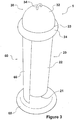
- the receptacle 1 is shown with the lid 30 in the closed position.
- the sides 31 (obscured in Figure 3 ) of the lid 30 are positioned below the open top 23 of the body 20.
- the aperture 35 is therefore also below the open top 23 of body 20 and lies adjacent to the sides 22 of the body.
- This visual effect is important as it maintains the clean lines of the receptacle as a whole.
- the aperture 35 is within the body 20, any waste material that may be visible about the aperture 35 is held within the body 20.
- the receptacle is therefore more hygienic as waste material is within the receptacle body 20, rather than on the outside of the receptacle body 20 as would occur if the lid was positioned outside the body 20.
- the support means 60 is a pedestal arrangement which includes of a base 65 adapted to sit on the floor or other such surface.
- the base will preferably be of any suitable heavy material to provide a low centre of gravity and thus provide stability.
- the base 65 may sit flat on the floor, or may include a plurality of feet (not shown). The feet would be in a configuration and number to maximise the stability of the receptacle 1.
- An elongate extension 66 is engageable with the base 65 at one end and engageable with a projection 62 at the other.
- the projection is attached to a rail 63 as described in Figures 1 and 2 .
- the receptacle 1 fits inside the rail 63 and the rail 63 abuts the concave side 26 of the external support flange 24 thus holding receptacle 1 in position also as described in Figures 1 and 2 .
- the elongate extension 66 would be of a sufficient length to allow the length of the receptacle to be supported above the base 65 when the flange is supported by the rail 63.
- the elongate extension 66 may also be of sufficient height to leave space between the base 21 of the body 20, and the top of the base 65 of the supporting means 60 to allow easy cleaning of the base 65 and the area around this.
- the elongate extension 66 can be of any shape or size as required, including for aesthetic requirements, as would be appreciated by persons skilled in the art.
- the elongate extension 66 is shown as a concave sheet which mirrors the shape of the body 20.
- the elongate extension 66 may preferably be of another configuration, for example a round pole (see also Figure 6 ) or a substantially rectangular shape.
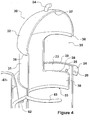
- Figure 4 shows detail of the receptacle 1 with the lid 30 in the open position.
- the body 20 may also include a protrusion 28 which acts as a retention mechanism that prevents the lid 30 from being completely removed from the body 20 when moved into the open position.
- the protrusion 28 is positioned at the upper portion of the body side 22.
- the lid 30 is initially fitted into body 20 by pressure exerted in the direction of base 21 of the body 20. This forces the lid side 31 to ride over the protrusion 28.
- the protrusion 28 sits within the aperture 35 as shown in Figure 4 .
- the bottom edge 38 of the aperture 35 catches on the protrusion 28, preventing the lid 30 from being easily removed from the body 20.
- the sides of aperture 35 prevent excess rotational movement.
- the lid wall 31 beneath the aperture 35 could include a channel (not shown) adapted to receive the protrusion 28.
- the channel would increase the ease by which the lid 30 could be inserted into body 20 over the protrusion 28.
- the channel may include a barrier to prevent the lid 30 from simply sliding out of the body 20 via the channel.
- the lid 30 could simply be rotated within the body 30 to take protrusion 28 out of line with the channel.
- the rotation of the lid 30 also allows the position of the aperture 35 to be placed at an angle accessible to the position of the user.
- the ability to rotate the lid thus allowing the user to adjust the position of the aperture 35 is a distinct advantage over the use of hinged or otherwise fixed lids. This allows greater utilisation of space while allowing ergonomic access to the aperture 35 by the user from either a seated or standing position.
- the rotation also ensures that the aperture 35 is easily accessible to the user when the lid 30 is in the open position, allowing for easy access of the waste into the receptacle 1, while also ensuring that sight into the receptacle 1 is minimised.
- the ability to rotate the lid 30 to at least a limited extent will be restricted to those receptacles that are cylindrical or otherwise circular in shape such as shown in the preferred embodiments of the Figures. This at least partial rotatability is why the cylindrical option is a very much preferred option. It may also be an option however, to have top portion of the lid 30 rotatable while the lower sides of the lid are not.
- the lid 30 may include a circumferential lip 36 (also indicated in Figure 2 ) which extends from the lid 30 and is positioned above the aperture 35.
- the lip 36 is preferably shaped to readily fit with the shape of flange 24.
- the lip 36 is positioned high enough so that the aperture 35 is inaccessible when the lid 30 is in the closed position. This ensures that no waste material can escape, and that the receptacle 1 is sealed when not in use to limit the extent of odours being released.
- the optional presence of lip 36 can further increase the hygienic advantages of the receptacle 1.
- the lip 36 need not be completely circumferential. Other options to prevent lid 30 movement into the body 20 may also be used.
- the lid 30 may also include on the inside surface, for example at 37 in Figure 4 , a hook or other such fastening means to allow the attachment of freshness products.
- a hook or other such fastening means for example antibacterial scented quills which would allow a fresh scent to escape when the lid 30 is moved into the open position.
- antibacterial scented quills which would allow a fresh scent to escape when the lid 30 is moved into the open position.
- Such options were only able to be readily provided by placing freshness products in the base of the receptacle. This had the disadvantage that waste products would cover the freshness products limiting and interfering with the scent over time.
- the present invention allows the option of overcoming this distinct disadvantage.
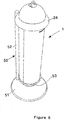
- Figure 6 shows the receptacle 1 in a closed position held by an alternative form of support means 50.
- the support means is in the form of a pedestal having a wide and preferably weighted base 51 together with a stand 52.
- the stand 52 has a loop (obscured in Figure 6 ), that could be a partial loop or a complete loop, which is adapted to fit under the flange 24 and hold the receptacle 1 in place.
- the base 51 includes a recess (obscured in Figure 6 ) that is adapted to receive the domed shaped bottom 53 (partially obscured in Figure 6 ) of receptacle 1.
- This support means 50 is therefore a stable and secure support option for the receptacle 1 in its preferred form having a domed bottom.
- Such support means also forming part of the invention to which the application is directed.
- the concave nature of the underside 26 of the flange 24 can assist in ease of carrying the bin.
- the flange 24 may also be adapted for use in storing the receptacles, or in stowing them for transport (not shown).
- a series of racks may be provided, for example in a truck or in a stand alone unit, which may allow the receptacles to be suspended from the racks via the flange 24.
- the racks may be substantially horizontal, and in contact with opposite sides of the receptacle via the flange.
- individual support means may be provided, which are adapted to receive the receptacles in a similar manner to the support means described above.
- Other options for stowage may be used as would be known in the art.
- the stowage options may take advantage of the locking mechanism 27 if required, for example in truck transportation where the loads in the truck may be required to be kept secure.
- the supporting means may be a claw shaped support which extends from the wall in which the receptacle may fit.
- the mounting surface to which the receptacle is attached is preferably a vertical wall.
- the apparatus could be attached to surfaces having curved or other angular aspects if needed.
- the combination of receptacle plus means support capable of being a kit.
- the receptacle may fit into an opening in a bench top so that the flange 24 abuts the bench top surface around the opening, thereby holding the upper portion of the receptacle 1 in an accessible position above the bench top.
- the lower portion of the receptacle 1 could be obscured below the bench top, for example by means of a cupboard or wall.
- Such alternative support means which exploit flange 24 and/or the shape of the receptacle 1 would be appreciated by persons skilled in the art.
- the base 21 of the receptacle 1 may be substantially flat, allowing the receptacle 1 to sit independently of a support means on the floor or other such surface.
- the domed shape of the base as shown in the Figures is however, preferred.
- the receptacle 1 may also be made of any suitable material and by manufacturing methods that would be well known in the art. When the receptacle is made of plastics material, these manufacturing methods would include blow or injection moulding techniques for example.
Landscapes
- Engineering & Computer Science (AREA)
- Mechanical Engineering (AREA)
- Refuse Receptacles (AREA)
- Closures For Containers (AREA)
Claims (14)
- Abfallbeseitigungsbehälter (1), umfassend einen Körper (20) und einen Deckel (30);
wobei der Körper (20) durch eine Basis (21), eine Seite (22) und eine offene Oberseite (23) definiert ist; und der Deckel (30) durch eine Seite (31), eine Oberseite (32) und eine offene Basis (33) definiert ist und eine Öffnung (35) in der Seite (31) aufweist, durch die Material in den Behälter (1) eingebracht werden kann; wobei das Material beim Platzieren in den Behälter (1) über die Öffnung (35) durch die offene Basis (33) des Deckels (30) in den Körper (20) fällt; und wobei der Körper (20) und der Deckel (30) zylindrisch sind;
dadurch gekennzeichnet, dass:das Zusammenwirken zwischen der Deckelseite (31) und der Körperseite (22) eine im Wesentlichen luftdichte Dichtung bildet;wobei die Seite des Deckels (30) zur Aufnahme in dem Körper (20) ausgeführt ist und reversibel und teleskopisch zwischen einer geöffneten und einer geschlossenen Position beweglich ist, so dass, wenn sich der Deckel (30) in der geschlossenen Position befindet, die Öffnung (35) durch die Körperseite (22) bedeckt wird, und wenn sich der Deckel (30) in der geöffneten Position befindet, die Öffnung (35) freiliegt, wobei der Deckel (30) auf der Basis (21) in mindestens einem begrenzten Ausmaß drehbar ist; und wobei der Körper (20) einen Rückhaltemechanismus aufweist, der verhindert, dass der Deckel (30) leicht von innerhalb des Körpers (20) entfernt wird. - Behälter (1) nach Anspruch 1, der ein Öffnungsmittel (34) zum Unterstützen eines Benutzers beim Bewegen des Deckels (30) aus der geschlossenen in die geöffneten Position aufweist.
- Behälter (1) nach Anspruch 2, wobei das Öffnungsmittel (34) ein an dem Deckel (30) angebrachter Griff ist.
- Behälter (1) nach Anspruch 1, wobei der Deckel (30) eine Lippe (36) aufweist, die verhindert, dass sich die Oberseite (32) des Deckels (30) an der offenen Oberseite (23) des Körpers (20) vorbeibewegt, wenn sich der Behälter (1) in der geschlossenen Position befindet.
- Behälter (1) nach einem der vorhergehenden Ansprüche, wobei der Körper (20) ferner einen äußeren Stützflansch (24) aufweist.
- Behälter (1) nach einem der vorhergehenden Ansprüche, wobei die Basis (21) des Körpers (20) eine kuppelförmige oder flache Außenfläche aufweist.
- Behälter (1) nach Anspruch 6, wobei die Basis (21) des Körpers (20) flach ist und dazu ausgeführt ist den Behälter (1) frei stehend zu stützen.
- Behälter (1) nach einem der vorhergehenden Ansprüche, wobei der Deckel (30) ein Befestigungsmittel aufweist, das an der Innenseite der Deckelseite (31) angebracht ist, wobei das Befestigungsmittel dazu ausgeführt ist, ein Anbringen von Frischeprodukten innerhalb des Behälters (1) zu gestatten.
- Behälter (1) nach Anspruch 4, wobei sich die Lippe (36) um den Umfang der Deckelseite (31) befindet.
- Behälter (1) nach Anspruch 4, wobei sich die Lippe (36) nicht um den Umfang befindet, sondern sich ausreichend um die Deckelseite (31) erstreckt, so dass sie sich zumindest über die Länge der Öffnung (35) erstreckt.
- Behälter (1) nach einem der vorhergehenden Ansprüche zusammen mit einem Stützmittel (60), wobei der Behälterkörper (20) ferner einen äußeren Stützflansch (24) aufweist und das Stützmittel (60) dazu ausgeführt ist, mit dem äußeren Stützflansch (24) zusammenzuwirken, um den Behälter (1) lösbar an dem Stützmittel (60) anzubringen.
- Behälter (1) nach Anspruch 11, wobei das Stützmittel (60) ferner an einer Montagefläche angebracht werden kann.
- Behälter (1) nach Anspruch 11, wobei das Stützmittel (60) ein Ständer ist.
- Behälter (1) nach Anspruch 12, wobei die Montagefläche eine Wand ist.
Applications Claiming Priority (2)
| Application Number | Priority Date | Filing Date | Title |
|---|---|---|---|
| NZ533197A NZ533197A (en) | 2004-05-28 | 2004-05-28 | Waste disposal receptacle |
| PCT/NZ2005/000107 WO2005115882A1 (en) | 2004-05-28 | 2005-05-30 | Waste disposal receptacle |
Publications (3)
| Publication Number | Publication Date |
|---|---|
| EP1753677A1 EP1753677A1 (de) | 2007-02-21 |
| EP1753677A4 EP1753677A4 (de) | 2009-03-18 |
| EP1753677B1 true EP1753677B1 (de) | 2020-02-19 |
Family
ID=35450772
Family Applications (1)
| Application Number | Title | Priority Date | Filing Date |
|---|---|---|---|
| EP05747520.4A Expired - Lifetime EP1753677B1 (de) | 2004-05-28 | 2005-05-30 | Abfallbeseitigungsbehälter |
Country Status (8)
| Country | Link |
|---|---|
| US (1) | US7798358B2 (de) |
| EP (1) | EP1753677B1 (de) |
| CN (1) | CN1906100A (de) |
| AU (1) | AU2005247828B2 (de) |
| CA (1) | CA2568424C (de) |
| NZ (1) | NZ533197A (de) |
| WO (1) | WO2005115882A1 (de) |
| ZA (1) | ZA200610709B (de) |
Families Citing this family (11)
| Publication number | Priority date | Publication date | Assignee | Title |
|---|---|---|---|---|
| EP2316285B1 (de) * | 2009-10-29 | 2013-05-01 | Quadria | Geländerpfosten mit Aufnahmegefäß für kleine Abfälle, insbesondere Zigarettenstummel |
| CA2914623C (en) * | 2013-06-04 | 2022-10-18 | Butler Concepts Limited | Improvements in, or related to, sanitary containers |
| US9549616B2 (en) * | 2015-06-09 | 2017-01-24 | Schilligo Jerry F | Accessory holder |
| CN105501749B (zh) * | 2016-01-07 | 2017-06-23 | 安庆市兴龙印业有限责任公司 | 一种厕所废纸存放盒 |
| US11110035B1 (en) * | 2016-02-05 | 2021-09-07 | Gram Tactical Llc | Tactical medicine dispensers |
| GB2557672B (en) * | 2016-12-15 | 2019-10-16 | Woosh Washrooms | Sanitary apparatus |
| USD837473S1 (en) | 2017-04-11 | 2019-01-01 | Magnuson Group, Inc. | Waste receptacle |
| US10543982B2 (en) | 2017-05-23 | 2020-01-28 | Magnuson Group Inc. | Waste receptacle |
| CN111050688B (zh) * | 2017-06-30 | 2023-05-09 | 史赛克公司 | 废物处置系统和用于接收和处置药物废料的废物接收器 |
| USD893821S1 (en) * | 2017-08-02 | 2020-08-18 | Woosh Washrooms | Sanitary bin |
| US12064797B2 (en) | 2018-12-27 | 2024-08-20 | Stryker Corporation | Method of disposing of waste receiver, waste receiver for pharmaceutical waste and method of assembling the waste receiver |
Family Cites Families (33)
| Publication number | Priority date | Publication date | Assignee | Title |
|---|---|---|---|---|
| US575621A (en) * | 1897-01-19 | smith | ||
| US1023276A (en) * | 1911-04-24 | 1912-04-16 | Frank L Rouse | Trick cigar-case. |
| US1506273A (en) * | 1923-05-04 | 1924-08-26 | Herbert E Smith | Sliver can |
| US2214437A (en) * | 1939-10-04 | 1940-09-10 | Continental Can Co | Dispensing container |
| US2367019A (en) * | 1944-06-02 | 1945-01-09 | Charles J Haag | Dispensing package |
| US2763395A (en) * | 1952-06-06 | 1956-09-18 | Airkem Inc | Diffuser devices |
| US2759625A (en) * | 1954-06-17 | 1956-08-21 | Ritter John | Refuse container |
| US3105592A (en) * | 1961-05-18 | 1963-10-01 | Cohen William | Telescopic form containers and dispensers |
| US3286872A (en) * | 1964-03-06 | 1966-11-22 | Jr Ralph V Burdick | Expandable box with non-removable cover |
| US3286717A (en) * | 1965-10-13 | 1966-11-22 | Lester A Teegardin | Coin holder |
| US3762539A (en) * | 1971-07-22 | 1973-10-02 | G Kerr | Pill dispenser |
| US3791514A (en) * | 1972-01-24 | 1974-02-12 | Designers Q Inc | Container for film magazine |
| US4234093A (en) * | 1979-05-21 | 1980-11-18 | Tyson Raymond K | Pill dispenser with safety features |
| US4261461A (en) * | 1979-09-10 | 1981-04-14 | Mateflex/Mele Corporation | Shadow box shipping/display container |
| US4353379A (en) * | 1981-03-06 | 1982-10-12 | Rafael Castellanos | Portable personal ash receiver |
| GB8422881D0 (en) | 1984-09-11 | 1984-10-17 | Chudzikowski R J | Closure device |
| US4618444A (en) * | 1984-09-17 | 1986-10-21 | Purex Corporation | Household laundry detergent with dual strength bleach |
| US4544063A (en) * | 1984-10-05 | 1985-10-01 | Neward Lance M | Closure for receptacle |
| US5082132A (en) | 1989-12-15 | 1992-01-21 | Tsai Wei C | Sanitary trash bin |
| US5213294A (en) * | 1992-03-18 | 1993-05-25 | Debord Walter J | Locking support for refuse can |
| US5651231A (en) * | 1994-08-26 | 1997-07-29 | Garland; Thomas A. | Valving |
| JPH08157004A (ja) * | 1994-12-02 | 1996-06-18 | Matsushita Electric Ind Co Ltd | 汚物収納容器 |
| US5620109A (en) * | 1995-06-26 | 1997-04-15 | Madden; Mark L. | Asymmetrical portable dispenser |
| US5608940A (en) * | 1995-08-07 | 1997-03-11 | L.A.P. Innovations, Inc. | Combination toothbrush and storage/dispenser apparatus and method of making the same thereof |
| DE19700822A1 (de) | 1997-01-13 | 1998-07-16 | 4 P Nicolaus Kempten Gmbh | Behälter |
| US5915560A (en) * | 1997-05-03 | 1999-06-29 | George; Donald C. | Compartmentalized pill dispenser |
| US6267461B1 (en) * | 1998-06-23 | 2001-07-31 | James L. Dunagan | Sport ball storage apparatus and method for storing and dispensing a sport ball |
| DE10108884A1 (de) * | 2001-02-15 | 2002-09-05 | Christoph Obst | Mülleimer mit Deckel |
| US6364147B1 (en) * | 2001-05-04 | 2002-04-02 | Creative Bath Products, Inc | Waste can with concealed waste bag and swing-open lid |
| US20040026420A1 (en) * | 2002-08-01 | 2004-02-12 | Huhtamaki Consumer Packaging, Inc. | Rotatable dispenser closure for use with a container |
| US7007818B2 (en) * | 2002-12-09 | 2006-03-07 | Laura Ann Martin | Container assembly |
| USD495250S1 (en) * | 2003-02-27 | 2004-08-31 | Historic Originals Limited | Elliptical box |
| EP1500613A1 (de) * | 2003-07-21 | 2005-01-26 | PHF Creation, Société à Responsabilité Limitée | Müllbehälter, insbesondere zur Verwendung im öffenlichen Bereich |
-
2004
- 2004-05-28 NZ NZ533197A patent/NZ533197A/en not_active IP Right Cessation
-
2005
- 2005-05-30 CN CNA2005800017533A patent/CN1906100A/zh active Pending
- 2005-05-30 WO PCT/NZ2005/000107 patent/WO2005115882A1/en not_active Ceased
- 2005-05-30 EP EP05747520.4A patent/EP1753677B1/de not_active Expired - Lifetime
- 2005-05-30 US US11/597,788 patent/US7798358B2/en not_active Expired - Lifetime
- 2005-05-30 AU AU2005247828A patent/AU2005247828B2/en not_active Ceased
- 2005-05-30 CA CA2568424A patent/CA2568424C/en not_active Expired - Lifetime
-
2006
- 2006-12-19 ZA ZA2006/10709A patent/ZA200610709B/en unknown
Non-Patent Citations (1)
| Title |
|---|
| None * |
Also Published As
| Publication number | Publication date |
|---|---|
| EP1753677A4 (de) | 2009-03-18 |
| EP1753677A1 (de) | 2007-02-21 |
| US20080087668A1 (en) | 2008-04-17 |
| CN1906100A (zh) | 2007-01-31 |
| US7798358B2 (en) | 2010-09-21 |
| ZA200610709B (en) | 2008-05-28 |
| CA2568424A1 (en) | 2005-12-08 |
| CA2568424C (en) | 2013-07-30 |
| WO2005115882A1 (en) | 2005-12-08 |
| AU2005247828A1 (en) | 2005-12-08 |
| NZ533197A (en) | 2006-10-27 |
| AU2005247828B2 (en) | 2011-06-23 |
Similar Documents
| Publication | Publication Date | Title |
|---|---|---|
| US5718168A (en) | Trash and recycling center | |
| EP1753677B1 (de) | Abfallbeseitigungsbehälter | |
| US6199714B1 (en) | Waste receptacle with swept debris pick up and features to maximize convenient use of receptacle liners | |
| US6179151B1 (en) | Garbage container | |
| US5163579A (en) | Trash receptacle with retractable foot pedal | |
| US7086569B2 (en) | All-purpose dispenser | |
| US6705575B1 (en) | Disposable bag with stand | |
| JP3459802B2 (ja) | 小出し組立体付き容器 | |
| US4655373A (en) | Water pitcher | |
| CA2624663C (en) | Refuse container | |
| US20080173648A1 (en) | Trash receptacle with bag retention system | |
| US4893719A (en) | Compartmentalized separating container | |
| EP1923333A1 (de) | Papierkorbanordnung | |
| MX2008002714A (es) | Recipiente para surtido y desecho. | |
| US20200290798A1 (en) | Receptacle and its method of manufacture | |
| US3643266A (en) | Portable waste receptacle | |
| US20110220654A1 (en) | Trash can with an adjustable draft compartment apparatus | |
| US3075692A (en) | Wall hung trash receptacle | |
| EP2768748B1 (de) | Belüfteter behälter zur aufbewahrung mehrerer arten von abfällen | |
| BE1032305B1 (nl) | Vuilbak | |
| CA2476169A1 (en) | Garbage tray for countertop | |
| KR100892076B1 (ko) | 주방용 쓰레기통 | |
| CA1272706A (en) | Counter top waste disposal unit | |
| WO2020178571A1 (en) | Janitorial trolley | |
| CA2331938A1 (en) | Collapsible bag holder |
Legal Events
| Date | Code | Title | Description |
|---|---|---|---|
| PUAI | Public reference made under article 153(3) epc to a published international application that has entered the european phase |
Free format text: ORIGINAL CODE: 0009012 |
|
| 17P | Request for examination filed |
Effective date: 20061227 |
|
| AK | Designated contracting states |
Kind code of ref document: A1 Designated state(s): AT BE BG CH CY CZ DE DK EE ES FI FR GB GR HU IE IS IT LI LT LU MC NL PL PT RO SE SI SK TR |
|
| DAX | Request for extension of the european patent (deleted) | ||
| REG | Reference to a national code |
Ref country code: HK Ref legal event code: DE Ref document number: 1100918 Country of ref document: HK |
|
| RAP1 | Party data changed (applicant data changed or rights of an application transferred) |
Owner name: FUMACARE LIMITED |
|
| A4 | Supplementary search report drawn up and despatched |
Effective date: 20090212 |
|
| 17Q | First examination report despatched |
Effective date: 20110512 |
|
| RAP1 | Party data changed (applicant data changed or rights of an application transferred) |
Owner name: BUTLER CONCEPTS LIMITED |
|
| STAA | Information on the status of an ep patent application or granted ep patent |
Free format text: STATUS: EXAMINATION IS IN PROGRESS |
|
| GRAP | Despatch of communication of intention to grant a patent |
Free format text: ORIGINAL CODE: EPIDOSNIGR1 |
|
| STAA | Information on the status of an ep patent application or granted ep patent |
Free format text: STATUS: GRANT OF PATENT IS INTENDED |
|
| INTG | Intention to grant announced |
Effective date: 20190717 |
|
| GRAJ | Information related to disapproval of communication of intention to grant by the applicant or resumption of examination proceedings by the epo deleted |
Free format text: ORIGINAL CODE: EPIDOSDIGR1 |
|
| GRAL | Information related to payment of fee for publishing/printing deleted |
Free format text: ORIGINAL CODE: EPIDOSDIGR3 |
|
| STAA | Information on the status of an ep patent application or granted ep patent |
Free format text: STATUS: EXAMINATION IS IN PROGRESS |
|
| GRAS | Grant fee paid |
Free format text: ORIGINAL CODE: EPIDOSNIGR3 |
|
| GRAR | Information related to intention to grant a patent recorded |
Free format text: ORIGINAL CODE: EPIDOSNIGR71 |
|
| STAA | Information on the status of an ep patent application or granted ep patent |
Free format text: STATUS: GRANT OF PATENT IS INTENDED |
|
| INTC | Intention to grant announced (deleted) | ||
| GRAA | (expected) grant |
Free format text: ORIGINAL CODE: 0009210 |
|
| STAA | Information on the status of an ep patent application or granted ep patent |
Free format text: STATUS: THE PATENT HAS BEEN GRANTED |
|
| INTG | Intention to grant announced |
Effective date: 20200106 |
|
| AK | Designated contracting states |
Kind code of ref document: B1 Designated state(s): AT BE BG CH CY CZ DE DK EE ES FI FR GB GR HU IE IS IT LI LT LU MC NL PL PT RO SE SI SK TR |
|
| REG | Reference to a national code |
Ref country code: GB Ref legal event code: FG4D |
|
| REG | Reference to a national code |
Ref country code: CH Ref legal event code: EP |
|
| REG | Reference to a national code |
Ref country code: DE Ref legal event code: R096 Ref document number: 602005056630 Country of ref document: DE |
|
| REG | Reference to a national code |
Ref country code: AT Ref legal event code: REF Ref document number: 1234717 Country of ref document: AT Kind code of ref document: T Effective date: 20200315 |
|
| REG | Reference to a national code |
Ref country code: IE Ref legal event code: FG4D |
|
| REG | Reference to a national code |
Ref country code: NL Ref legal event code: MP Effective date: 20200219 |
|
| PG25 | Lapsed in a contracting state [announced via postgrant information from national office to epo] |
Ref country code: FI Free format text: LAPSE BECAUSE OF FAILURE TO SUBMIT A TRANSLATION OF THE DESCRIPTION OR TO PAY THE FEE WITHIN THE PRESCRIBED TIME-LIMIT Effective date: 20200219 |
|
| REG | Reference to a national code |
Ref country code: LT Ref legal event code: MG4D |
|
| PG25 | Lapsed in a contracting state [announced via postgrant information from national office to epo] |
Ref country code: IS Free format text: LAPSE BECAUSE OF FAILURE TO SUBMIT A TRANSLATION OF THE DESCRIPTION OR TO PAY THE FEE WITHIN THE PRESCRIBED TIME-LIMIT Effective date: 20200619 Ref country code: BG Free format text: LAPSE BECAUSE OF FAILURE TO SUBMIT A TRANSLATION OF THE DESCRIPTION OR TO PAY THE FEE WITHIN THE PRESCRIBED TIME-LIMIT Effective date: 20200519 Ref country code: GR Free format text: LAPSE BECAUSE OF FAILURE TO SUBMIT A TRANSLATION OF THE DESCRIPTION OR TO PAY THE FEE WITHIN THE PRESCRIBED TIME-LIMIT Effective date: 20200520 Ref country code: SE Free format text: LAPSE BECAUSE OF FAILURE TO SUBMIT A TRANSLATION OF THE DESCRIPTION OR TO PAY THE FEE WITHIN THE PRESCRIBED TIME-LIMIT Effective date: 20200219 |
|
| PG25 | Lapsed in a contracting state [announced via postgrant information from national office to epo] |
Ref country code: NL Free format text: LAPSE BECAUSE OF FAILURE TO SUBMIT A TRANSLATION OF THE DESCRIPTION OR TO PAY THE FEE WITHIN THE PRESCRIBED TIME-LIMIT Effective date: 20200219 |
|
| PG25 | Lapsed in a contracting state [announced via postgrant information from national office to epo] |
Ref country code: DK Free format text: LAPSE BECAUSE OF FAILURE TO SUBMIT A TRANSLATION OF THE DESCRIPTION OR TO PAY THE FEE WITHIN THE PRESCRIBED TIME-LIMIT Effective date: 20200219 Ref country code: EE Free format text: LAPSE BECAUSE OF FAILURE TO SUBMIT A TRANSLATION OF THE DESCRIPTION OR TO PAY THE FEE WITHIN THE PRESCRIBED TIME-LIMIT Effective date: 20200219 Ref country code: SK Free format text: LAPSE BECAUSE OF FAILURE TO SUBMIT A TRANSLATION OF THE DESCRIPTION OR TO PAY THE FEE WITHIN THE PRESCRIBED TIME-LIMIT Effective date: 20200219 Ref country code: PT Free format text: LAPSE BECAUSE OF FAILURE TO SUBMIT A TRANSLATION OF THE DESCRIPTION OR TO PAY THE FEE WITHIN THE PRESCRIBED TIME-LIMIT Effective date: 20200712 Ref country code: CZ Free format text: LAPSE BECAUSE OF FAILURE TO SUBMIT A TRANSLATION OF THE DESCRIPTION OR TO PAY THE FEE WITHIN THE PRESCRIBED TIME-LIMIT Effective date: 20200219 Ref country code: ES Free format text: LAPSE BECAUSE OF FAILURE TO SUBMIT A TRANSLATION OF THE DESCRIPTION OR TO PAY THE FEE WITHIN THE PRESCRIBED TIME-LIMIT Effective date: 20200219 Ref country code: RO Free format text: LAPSE BECAUSE OF FAILURE TO SUBMIT A TRANSLATION OF THE DESCRIPTION OR TO PAY THE FEE WITHIN THE PRESCRIBED TIME-LIMIT Effective date: 20200219 Ref country code: LT Free format text: LAPSE BECAUSE OF FAILURE TO SUBMIT A TRANSLATION OF THE DESCRIPTION OR TO PAY THE FEE WITHIN THE PRESCRIBED TIME-LIMIT Effective date: 20200219 |
|
| REG | Reference to a national code |
Ref country code: AT Ref legal event code: MK05 Ref document number: 1234717 Country of ref document: AT Kind code of ref document: T Effective date: 20200219 |
|
| REG | Reference to a national code |
Ref country code: DE Ref legal event code: R097 Ref document number: 602005056630 Country of ref document: DE |
|
| REG | Reference to a national code |
Ref country code: DE Ref legal event code: R119 Ref document number: 602005056630 Country of ref document: DE |
|
| PLBE | No opposition filed within time limit |
Free format text: ORIGINAL CODE: 0009261 |
|
| STAA | Information on the status of an ep patent application or granted ep patent |
Free format text: STATUS: NO OPPOSITION FILED WITHIN TIME LIMIT |
|
| REG | Reference to a national code |
Ref country code: HK Ref legal event code: WD Ref document number: 1100918 Country of ref document: HK |
|
| 26N | No opposition filed |
Effective date: 20201120 |
|
| PG25 | Lapsed in a contracting state [announced via postgrant information from national office to epo] |
Ref country code: MC Free format text: LAPSE BECAUSE OF FAILURE TO SUBMIT A TRANSLATION OF THE DESCRIPTION OR TO PAY THE FEE WITHIN THE PRESCRIBED TIME-LIMIT Effective date: 20200219 Ref country code: IT Free format text: LAPSE BECAUSE OF FAILURE TO SUBMIT A TRANSLATION OF THE DESCRIPTION OR TO PAY THE FEE WITHIN THE PRESCRIBED TIME-LIMIT Effective date: 20200219 Ref country code: CH Free format text: LAPSE BECAUSE OF NON-PAYMENT OF DUE FEES Effective date: 20200531 Ref country code: LI Free format text: LAPSE BECAUSE OF NON-PAYMENT OF DUE FEES Effective date: 20200531 Ref country code: AT Free format text: LAPSE BECAUSE OF FAILURE TO SUBMIT A TRANSLATION OF THE DESCRIPTION OR TO PAY THE FEE WITHIN THE PRESCRIBED TIME-LIMIT Effective date: 20200219 |
|
| PG25 | Lapsed in a contracting state [announced via postgrant information from national office to epo] |
Ref country code: SI Free format text: LAPSE BECAUSE OF FAILURE TO SUBMIT A TRANSLATION OF THE DESCRIPTION OR TO PAY THE FEE WITHIN THE PRESCRIBED TIME-LIMIT Effective date: 20200219 Ref country code: PL Free format text: LAPSE BECAUSE OF FAILURE TO SUBMIT A TRANSLATION OF THE DESCRIPTION OR TO PAY THE FEE WITHIN THE PRESCRIBED TIME-LIMIT Effective date: 20200219 |
|
| REG | Reference to a national code |
Ref country code: BE Ref legal event code: MM Effective date: 20200531 |
|
| PG25 | Lapsed in a contracting state [announced via postgrant information from national office to epo] |
Ref country code: LU Free format text: LAPSE BECAUSE OF NON-PAYMENT OF DUE FEES Effective date: 20200530 |
|
| PG25 | Lapsed in a contracting state [announced via postgrant information from national office to epo] |
Ref country code: IE Free format text: LAPSE BECAUSE OF NON-PAYMENT OF DUE FEES Effective date: 20200530 Ref country code: FR Free format text: LAPSE BECAUSE OF NON-PAYMENT OF DUE FEES Effective date: 20200531 |
|
| PG25 | Lapsed in a contracting state [announced via postgrant information from national office to epo] |
Ref country code: BE Free format text: LAPSE BECAUSE OF NON-PAYMENT OF DUE FEES Effective date: 20200531 Ref country code: DE Free format text: LAPSE BECAUSE OF NON-PAYMENT OF DUE FEES Effective date: 20201201 |
|
| PG25 | Lapsed in a contracting state [announced via postgrant information from national office to epo] |
Ref country code: TR Free format text: LAPSE BECAUSE OF FAILURE TO SUBMIT A TRANSLATION OF THE DESCRIPTION OR TO PAY THE FEE WITHIN THE PRESCRIBED TIME-LIMIT Effective date: 20200219 Ref country code: CY Free format text: LAPSE BECAUSE OF FAILURE TO SUBMIT A TRANSLATION OF THE DESCRIPTION OR TO PAY THE FEE WITHIN THE PRESCRIBED TIME-LIMIT Effective date: 20200219 |
|
| PGFP | Annual fee paid to national office [announced via postgrant information from national office to epo] |
Ref country code: GB Payment date: 20240502 Year of fee payment: 20 |
|
| REG | Reference to a national code |
Ref country code: GB Ref legal event code: PE20 Expiry date: 20250529 |
|
| PG25 | Lapsed in a contracting state [announced via postgrant information from national office to epo] |
Ref country code: GB Free format text: LAPSE BECAUSE OF EXPIRATION OF PROTECTION Effective date: 20250529 |