EP1753668B1 - Self-cleaning lid for a paint container fluid pour spout - Google Patents
Self-cleaning lid for a paint container fluid pour spout Download PDFInfo
- Publication number
- EP1753668B1 EP1753668B1 EP05759548.0A EP05759548A EP1753668B1 EP 1753668 B1 EP1753668 B1 EP 1753668B1 EP 05759548 A EP05759548 A EP 05759548A EP 1753668 B1 EP1753668 B1 EP 1753668B1
- Authority
- EP
- European Patent Office
- Prior art keywords
- paint
- substrate
- cover element
- pour spout
- self
- Prior art date
- Legal status (The legal status is an assumption and is not a legal conclusion. Google has not performed a legal analysis and makes no representation as to the accuracy of the status listed.)
- Expired - Lifetime
Links
Images


Classifications
-
- B—PERFORMING OPERATIONS; TRANSPORTING
- B44—DECORATIVE ARTS
- B44D—PAINTING OR ARTISTIC DRAWING, NOT OTHERWISE PROVIDED FOR; PRESERVING PAINTINGS; SURFACE TREATMENT TO OBTAIN SPECIAL ARTISTIC SURFACE EFFECTS OR FINISHES
- B44D3/00—Accessories or implements for use in connection with painting or artistic drawing, not otherwise provided for; Methods or devices for colour determination, selection, or synthesis, e.g. use of colour tables
- B44D3/12—Paint cans; Brush holders; Containers for storing residual paint
- B44D3/127—Covers or lids for paint cans
-
- B—PERFORMING OPERATIONS; TRANSPORTING
- B01—PHYSICAL OR CHEMICAL PROCESSES OR APPARATUS IN GENERAL
- B01F—MIXING, e.g. DISSOLVING, EMULSIFYING OR DISPERSING
- B01F27/00—Mixers with rotary stirring devices in fixed receptacles; Kneaders
- B01F27/80—Mixers with rotary stirring devices in fixed receptacles; Kneaders with stirrers rotating about a substantially vertical axis
- B01F27/88—Mixers with rotary stirring devices in fixed receptacles; Kneaders with stirrers rotating about a substantially vertical axis with a separate receptacle-stirrer unit that is adapted to be coupled to a drive mechanism
-
- B—PERFORMING OPERATIONS; TRANSPORTING
- B01—PHYSICAL OR CHEMICAL PROCESSES OR APPARATUS IN GENERAL
- B01F—MIXING, e.g. DISSOLVING, EMULSIFYING OR DISPERSING
- B01F33/00—Other mixers; Mixing plants; Combinations of mixers
- B01F33/50—Movable or transportable mixing devices or plants
- B01F33/501—Movable mixing devices, i.e. readily shifted or displaced from one place to another, e.g. portable during use
- B01F33/5011—Movable mixing devices, i.e. readily shifted or displaced from one place to another, e.g. portable during use portable during use, e.g. hand-held
Definitions
- This invention relates to a self-cleaning lid for use a paint container.
- the present invention is a fluid seal structure configured to prevent contaminants from entering a paint container through the pour spout and configured to prevent leakage of the paint past the container.
- paint vendors provide auto body repair businesses, such as body shops and jobbers, with their paint formulas.
- these paint formulas are a composition (i.e., mixture) of paint components, such as colorants, tints, pearls, metallics, binders and/or balancers, that, once mixed, produce the desired color of paint to be applied to a repaired vehicle.
- the paint formulas of the paint vendors are formulated to match the colors that have been applied to vehicles by new car manufacturers over the years.
- these paint formulas include variants, to match the color fading of paint that can occur to a vehicle over years of service.
- palettes of paint formulas of the paint vendors also have custom colors (i.e., unconventional colors not typically used by vehicle manufacturers) that may be used to produce special finishes for custom or show cars.
- paint vendors provide body shops and jobbers with literally thousands of paint formulas for producing the vast spectrum of colors needed in the automotive body repair industry.
- paint vendors would provide the body shops and jobbers with microfiche containing their paint formulas.
- Today the paint formulas are stored in computer memory.
- a system operator such as an employee of the body shop or jobber, first obtains the color code from the vehicle.
- This color code is typically part of the vehicle's identification number.
- the code for a particular color is obtained from a catalog.
- This color code is then entered into the microprocessor of the computer, which accesses the computer memory, and displays, via a monitor, the paint vendor's paint formula which matches the identified vehicle color code.
- the paint formulas are displayed according to the weight of the different paint components for mixing specific quantities of the paint formula, and the order in which the displayed paint components are to be mixed.
- paint formula mixing quantities are listed in quart, half gallon and gallon sizes, while the weight of the particular paint components needed to mix the desired quantity of paint, are listed in grams to a precision of a tenth of a gram.
- the paint components comprising tints, colorants, pearls and/or metallics are mixed first, while the paint components comprising binders and/or balancers are added last.
- the paint formula can require just a few paint components, or over a dozen paint components, that must be mixed with a great degree of precision, to achieve a perfect color match.
- the operator places a paint receptacle on a weigh cell that is linked to the microprocessor of the computer.
- a receptacle larger than the quantity of paint formula to be mixed is used to accommodate any excess paint inadvertently mixed by the operator.
- the operator With the receptacle on the weigh cell, the operator, to make ready for the process of adding paint components to the receptacle to mix the desired color paint formula, zeros the weigh cell.
- the various paint components (of which there are dozens) are stored in containers kept within a rack.
- the rack has a mechanism that periodically stirs the paint components within the containers, so that the various paint components are ready to be dispensed as part of the paint formula mixing process.
- these containers are the original quart and gallon sized metal containers within which the paint components are shipped to the body shop or jobber. In metric system countries, these containers are the original one-liter and four-liter sized metal containers within which the paint components are shipped to the body shop or jobber.
- Specialized paint container lids that include stirring paddles that work with the stirring mechanism of the rack replace the original covers of these containers. These specialized paint container lids also have pour spouts that allow the paint components of the containers to be dispensed (i.e., poured out) into the receptacle atop the weigh cell.
- the pour spout of the specialized paint container lid is covered by a cover element.
- the cover element for the pour spout is movable between an opened state in which the paint component can be poured from its container through the pour spout by tipping (i.e., tilting) the container, and a closed state.
- the specialized paint container lid typically includes a vent to allow air to enter the container to displace the liquid paint component dispensed from the pour spout.
- the system operator begins by identifying the first listed paint component of the paint formula to be mixed. The operator then pours, by hand, the paint component into the weigh cell supported paint receptacle, until the weight of the paint component dispensed (i.e., poured) into the receptacle matches what is displayed on the computer monitor. The operator continues along on this course (i.e., hand pouring the paint components from their containers), until the correct weight of all paint components, needed to mix the desired color paint formula, have been added to the paint receptacle atop the weigh cell.
- United States published patent application No. US 2001/0035437 A1 discloses a lid member for an original container of a liquid paint component.
- the lid member is usable with a system for dispensing the paint component from its original container into a paint receptacle according to a paint formula to form a liquid paint mixture.
- the lid member includes a base portion that is adapted to releasably engage an open top of the paint component container.
- the base portion has a pour spout through which the paint component can be dispensed, and a movable cover element.
- the cover element is movable between a closed state, wherein the cover element covers the pour spout, and an opened state, wherein the pour spout is uncovered and the paint component can be dispensed from its original container and into the paint receptacle.
- a resilient seal mechanism is positioned between the pour spout and the movable cover element for preventing leakage of the paint component, upon tilting of the original container, out of the pour spout past the cover element in its closed state.
- the present invention provides a self-cleaning lid for use with a paint container.
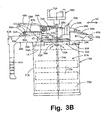
- FIGS. 1 and 2 A semi-automated dispensing system 10 for dispensing liquid paint components according to a paint formula to form a liquid paint mixture in accordance with the present invention is illustrated generally in FIGS. 1 and 2 .
- the dispensing system 10 generally comprises a dispensing apparatus 12 for dispensing a liquid paint component 14 from its original container 16A and 16B, and a control apparatus 18 for controlling the dispensing apparatus 12.
- FIGS. 1 , 3-8 show the quart size original container 16A having a lid member 20A
- FIG. 11 illustrates the gallon size original container 16B having a lid member 20B.
- the lid member 20A fits a one liter size original container and the lid member 20B fits a four liter size original container.
- the containers 16A and 16B are typical cylindrical shaped, metal vessels within which liquid paint components 14, such as tints, colorants, pearls, metallics, binders and balancers (used to mix automotive paint according to a paint formula) are shipped from a liquid paint component manufacturer to customers, such as body shops and jobbers.
- liquid paint components 14 such as tints, colorants, pearls, metallics, binders and balancers (used to mix automotive paint according to a paint formula) are shipped from a liquid paint component manufacturer to customers, such as body shops and jobbers.
- the quart size and gallon size containers 16A and 16B are substantially identical. Therefore, only the quart size original container will be described with particularity.
- the lid members 20A and 20B are substantially similar, therefore the quart size lid member 20A will be described with particularity, and only the differences in the gallon size lid member 20B relative to the quart size lid member 20A will be described with particularity.
- the original container 16A is cylindrical shaped having an open top 22A defined by a circumferential lip 24A.
- the lid member 20A includes a base portion 26A adapted to engage and seal the open top 22A of the container 16A to protect the liquid paint component 14 within the container 16A.
- the base portion 26A of the lid member 20A includes a pair of spaced, pivotable cam lock mechanisms 28A that are used to releasably secure the lid member 20A to the original container 16A.
- Each of the cam lock mechanisms 28A is defined by a cam element 30A connected to a cam actuator 32A by way of a post member 34A. Pivotally moving the cam actuators 32A by hand, as represented by double-headed arrow 36 (see FIG. 4 ), moves the cam elements 30A into and out of engagement with the lip 24A to secure and release the lid member 20A from the original container 16A.
- the lid member 20A further includes a handle 38A, for easy handling of the original container 16A when the lid member 20A is secured thereto.
- the handle 38A includes a first portion 39A generally parallel to the lip 24A of the original container 16A, a second portion 41 A (grasped by a user) that extends substantially perpendicular to the first portion 39, and a pair of oppositely directed dispensing system latch lugs 43A positioned at the intersection the first and second portions 39A, 41A.
- the purpose of the pair of dispensing system latch lugs 43A will become clear below.
- the pair of oppositely directed dispensing system latch lugs 43B are positioned along the length of the first portion 39B of the handle 38B instead of at the intersection of the first and second portions 39A and 41 A as in the quart size lid member 20A.
- this different positioning of the dispensing system latch lugs 43A, 43B constitutes the main and only real difference between the lid members 20A and 20B.
- the lid member 20A also includes a liquid paint component pour spout 40A having a rear wall 81A, first and second opposed side walls 83A and 85A, respectively, and a front pour wall 87A. Also as seen in FIG. 5 , immediately adjacent to (i.e., to the rear of) the rear wall 81 of the pour spout 40A, the lid member 20A includes first and second spaced guide surfaces 89A and 91A, respectively, the purpose of which will be made clear below.
- the pour spout 40A is covered by a linearly movable, as represented by double headed directional arrow 42 (see FIGS. 3A and 3B ), cover element 44A.
- the cover element 44A is linearly movable between a closed state (shown in FIG. 3A ) and an opened state (shown in FIG. 3B ).
- the liquid paint component 14 In the closed state of the cover element 44A, the liquid paint component 14 is prevented from being poured (i.e., dispensed) from the original container 16A through the pour spout 40A.
- the liquid paint component 14 In the opened state of the cover element 44A, the liquid paint component 14 can be poured from the original container 16A through the pour spout 40A by tilting the container 16A using the handle 38A.
- the cover element 44A is movable between its closed and opened states via a thumb actuator 46A that is pivotally secured to the base portion 26A by way of a pivot pin 48A.
- the thumb actuator 46A is pivotally movable as shown by double-headed directional arrow 47.
- the thumb actuator 46A is connected to the cover element 44A via a wire loop 50A.
- the thumb actuator 46A is biased to this normal position in a known manner by a coil spring element 54A (see FIGS. 3A and 3B ).
- the coil spring element 54A acts between the base portion 26A and the thumb actuator 46A.
- the thumb actuator 46A When the thumb actuator 46A is positioned as shown in FIG. 3B , the cover element 44A is in its opened state. The cover element 44A is moved, from its closed state to its opened state, through the connecting wire loop 50A by pivoting the thumb actuator 46A about the pivot pin 48A against the bias of the spring element 54A. The cover element 44A is allowed to return to its closed state from the opened state by simply releasing the thumb actuator 46A.
- the lid member 20A also includes a rotatable roller element 51A (see FIGS. 4 and 5 ) that bears against the wire loop 50A to help maintain a seal between the cover element 44A and the pour spout 40A. As seen in FIGS. 3-5 , the cover element 44A also includes a slot 49A the purpose of which will be made clear below.
- the walls 81A, 83A, 85A, 87A of the pour spout 40A define a circumferential, planar edge surface 350A
- the cover element 44A includes a planar lower surface 352A.
- a resilient seal mechanism 354 is positioned at an engagement interface between the circumferential, planar edge surface 350A of the pour spout 40A and the planar lower surface 352A of the cover element 44A. The resilient seal mechanism 354 prevents leakage, upon tilting of the original container 16A, of the liquid paint component 14 out of the pour spout 40A past the cover element 44A in the closed state of the cover element 44A.
- the resilient seal mechanism 354 defines a resilient seal member 357 that covers the entire planar lower surface 352A of the cover element 44A.
- the resilient seal member 357 comprises a first substrate 358 of a resilient material, such as foam, and a second substrate 360 of a smooth material.
- the second substrate 360 defines a downward projecting chevron 370 in three-dimensions such that the chevron 370 is configured to seal against a front portion (not shown) of the pour spout 40A when the pour spout 40A is in the closed state.
- the second substrate 360 is also known as a self-cleaning lid and can be any smooth material configured to resist bonding with the contents of the container 16A ( FIG. 3A ).
- the second substrate 360 is a thermoplastic polymer such as polyethylene.
- the second substrate 360 is a non-thermoplastic polymer such as polytetrafluoroethylene.
- the second substrate 360 is formed of a non-thermoplastic polymer known by the trademark TEFLON.
- the first substrate 358 has a thickness of approximately 0.008 mm (approximately 0.0003 inches) and the second substrate 360 has a thickness of approximately 0.0025mm (0.0001 inches).
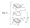
- FIG. 11 is an exploded view of the cover element 44A in relation to the resilient seal member 357.
- the first substrate 358 is coupled to the planar lower surface 352A of the cover element 44A.
- the planar lower surface 352A of the cover element 44A defines downwardly projecting pins 372 that communicate through the first substrate 358 and into, but not through, the second substrate 360.
- the first substrate 358 can be adhesively attached to the second substrate 360, the combination of which can be mounted to the planar lower surface 352A of the cover element 44A.
- the second substrate 360 extends from the cover element 44A and engages the circumferential, planar edge surface 350A of the pour spout 40A.
- the second substrate 360 defines a substrate side 380 and a spout side 382, where the substrate side 380 is adapted for attachment to the first substrate 358 and the spout side 382 is configured to slidingly move relative to the pour spout 40A ( FIG. 10 ) in dispensing paint.
- the spout side 382 defines the downward projecting chevron 370 in three-dimensions such that the chevron 370 is configured to seal against the pour spout 40A when the pour spout 40A is in the closed state.
- FIGS. 12A and 12B illustrate top views of the chevron 370 of the self-cleaning lid 360.
- the downward projecting chevron 370 defines an apex 390 and a base 392, where the apex 390 of the chevron 370 is adapted to mate with the lip of the pour spout 40A ( FIG. 10 ) when the pour spout 40A is in the closed state.
- the apex 390 of the chevron 370 is retracted away from the lip of the pour spout 40A such that paint is permitted to flow by the downwardly projecting chevron 370.
- the smoothness of the second substrate 360 allows the.cover element 44A to readily move relative to the pour spout 40A ( FIG. 10 ) between the open and closed states.
- the second substrate 360 is both smooth and configured to hermetically seal the pour spout 40A when in the closed state.
- the resiliency of the first substrate 358 allows the resilient seal member 357 to conform to the shape of the circumferential, planar edge surface 350A of the pour spout 40A.
- the resilient seal member 357 By conforming to the shape of the pour spout 40A, the resilient seal member 357 provides an excellent fluid seal that prevents contaminants from entering the original container 16A through the pour spout 40A, and prevents leakage, upon tilting of the original container 16A, of the liquid paint component 14 out of the pour spout 40A past the cover element 44A in the closed state of the cover element 44A. In addition, by conforming to the shape of the pour spout 40A, the resilient seal member 357 prevents paint near the exit of the pour spout from hardening into a clump.
- Hardened paint clumps impede the flow of paint from the pour spout 40A, and are associated with over-pouring when the clump gives way and the paint gushes out of the spout.
- the self-cleaning lid 360 prevents the liquid paint component 14 from blocking the pour spout 40A.
- the resilient seal member 357 and the second substrate 360 provide an excellent fluid seal that prevents contaminants from entering the original container 16A through the pour spout 40A, and prevents leakage, upon tilting of the original container 16A, of the liquid paint component 14 out of the pour spout 40A past the cover element 44A in the closed state of the cover element 44A.
- the resilient seal member 357 is secured to the planar lower surface 352A of the cover element 44A.
- a plurality of downwardly projecting pins 372 are integrally formed in the cover element 44A and extend from the planar lower surface 352A thereof.
- the spaced pins 372 engage the first substrate 358 and the second substrate 360 defining the resilient seal member 357.
- the first substrate 358 includes a plurality of spaced openings 396. In one preferred embodiment, there are four spaced openings 396 that are formed via die cutting.
- Each of the openings 396 is sized to closely receive one of the pins 372 to secure the first substrate 358 against the planar lower surface 352A of the cover element 44A.
- the pins 372 cooperate with the closely fitting openings 396 to hold the first substrate 358 to the cover element 44A via only frictional engagement.
- the second substrate 360 includes a plurality of cup shaped protruding portions 398.
- Each of the protruding portions 398 is sized to closely receive one of the pins 372 to secure the second substrate 360 against the first substrate 358 and to the planar lower surface 352A of the cover element 44A.
- the pins 372 cooperate with the closely fitting cup shaped protruding portions 398 to hold the second substrate 360 to the cover element 44A via only frictional engagement.
- the second substrate 360 includes an upstanding peripheral wall 400 that acts to enclose the first substrate 358.
- FIGS. 12A and 12B illustrate top views of the second substrate 360 showing the chevron 370.
- the downward projecting chevron 370 defines an apex 390 and a base 392, where the apex 390 of the chevron 370 is adapted to mate with the lip of the pour spout 40A ( FIG. 10 ) when the pour spout 40A is in the closed state.
- FIG. 13A is a side view of the second substrate 360 (the self-cleaning lid) oriented with the substrate side 380 up and showing the chevron 370.
- FIG. 13B is a side view of the second substrate 360 oriented with the spout side 382 up and showing the chevron 370.
- the base 392 of the chevron 370 extends downward (as oriented in FIG. 13A ) from the spout side 382 beyond the protruding portions 398.
- the apex 390 blends into the spout side 382.
- the chevron 370 is adapted to be positioned in the closed pour spout 40A ( FIG. 10 ) to impede the entrance of contaminants and to impede the drying and hardening of paint that has not left the container 16A ( FIG. 3A ).
- FIG. 14 is a front view of the second substrate 360 (the self-cleaning lid) showing the chevron 370. As shown, the chevron 370 extends downward (as oriented in FIG. 14 ) from the spout side 382. In the view of FIG. 14 , the protruding portions 398 are obstructed from view by the chevron 370.
- the first substrate 358 engages the planar lower surface 352A of the cover element 44A
- the second substrate 360 engages the circumferential, planar edge surface 350A of the pour spout 40A.
- the smoothness of the second substrate 360 allows the cover element 44A to readily move relative to the pour spout 40A between the open and closed states.
- the resiliency of the first substrate 358 combined with the flexibility of the second substrate 360, allows the resilient seal member 357 to conform to the shape of the circumferential, planar edge surface 350A of the pour spout 40A.
- cup shaped protruding portions 398 slidably receive the pins 372 so as to allow some movement of the second substrate 360 relative to the cover element 44A upon compression and extension of the first substrate 358.
- This movement of the second substrate 360 relative to the cover element 44A is substantially perpendicular to the planar lower surface 352A of the cover element 44A and allows the resilient seal member 357 to engage and conform to the shape of the circumferential, planar edge surface 350A of the pour spout 40A.
- the base portion 26A of the lid member 20A includes a vent member 53A defining a vent passage 55A that has a first open end 57A and an opposite second open end 59A.
- the vent passage 55A passes through the base portion 26A such that the first open end 57A communicates with an interior region 61 A of the original container 16A and the second open end 59A communicates with atmosphere.
- the second open end 59A is sealable by way of a linearly movable plug element 63A.
- the plug element 63A is linearly movable between a sealed position (see FIG.
- the plug element 63A is linearly movable between the sealed and unsealed positions by actuation of the thumb actuator 46A.
- the thumb actuator 46A is coupled to the plug element 63A by way of a wire loop element 67A that engages a groove 69A in the plug element 63A. Movement of the thumb actuator 46A between the positions shown in FIGS. 3A and 3B moves the plug element 63A (by way of the wire loop element 67A) between the sealed and unsealed positions. In the sealed position of the plug element 63A, contaminants are prevented from entering the vent passage 55A.
- the second open end 59A of the vent passage 55A is located radially exterior to the cylindrical side wall 71A of the original container 16A. This location of the second open end 59A of the vent passage 55A prevents the liquid paint component 14 from flowing out of the original container 16A through the vent passage 55A and the subsequent fouling of the exterior portions of the lid member 20A. This undesirable condition is prevented because the second open end 59A of the vent passage 55A is located above the fluid level of the liquid paint component 14 in the dispensing state of the liquid paint component illustrated in FIGS. 8 and 11 .
- the vent passage 55A extends substantially perpendicular to and radially from a central axis 73 of the original container 16A (see FIG. 3A ).
- the lid member 20A further includes an alignment slot 56A positioned at a first portion of the lid member 20A at the pour spout 40A adjacent to the cover element 44A.
- the alignment slot 56A is positioned so as to define a plane 60 that is parallel to an upper surface 62A of the circumferential lip 24A of the original container 16A. The purpose of the alignment slot 56A will become clear below.
- the alignment slot 56A is formed integrally with the base portion 26A of the lid member 20A.
- the lid member 20A further includes a stirring device 68A for stirring the liquid paint component 14 within the original container 16A.
- the stirring device 68A includes a plurality of paddles 70A connected to a paddle actuator 72A by way of a shaft member 74A. Rotating the paddle actuator 72A, as represented by double headed directional arrow 76, causes rotation of the paddles 70A and stirring of the liquid paint component 14.
- the paddle actuator 72A is driven (i.e., rotated) by a stirring mechanism (not shown) that is part of a storage rack (not shown) for holding various original containers 16A of liquid paint components 14.
- the dispensing apparatus 12 of the dispensing system 10 includes a support frame 80. As seen best in FIGS. 2 and 6 , the dispensing apparatus 12 further includes a receiving mechanism 98 for releasably engaging the original container 16A, 16B of the liquid paint component 14.
- the receiving mechanism 98 is defined by first and second engaging mechanisms 100 and 102, respectively.
- the first engaging mechanism 100 includes first and second spaced arms 104a and 104b rigidly mounted to the support frame so as to be fixed against movement relative thereto.
- a registration rod 108 rigidly connects together the first and second arms 104a and 104b at their free ends 110a and 110b.
- the registration rod 108 is adapted to releasably receive (i.e., engage) the alignment slot 56A of the lid member 20A.
- interengagement of the alignment slot 56A with the registration rod 108 mounts (i.e., secures) and aligns a first portion of the container 16A and lid member 20A combination to the receiving mechanism 98 of the dispensing apparatus 12.
- the second engaging mechanism 102 includes first and second spaced plates 111a and 111b fixed to an upper end of the support frame 80. Free ends 113a and 113b of the plates 111a, 111b includes latch slots 115a and 115b, respectively.
- the second engaging mechanism 102 further includes first and second spaced L-shaped arms 114a and 114b pivotally mounted to the support frame 80 via a pivot pin 116.
- a handle member 118 rigidly connects together the first and second L-shaped arms 114a and 114b at first ends 120a and 120b.
- Second ends 122a and 122b of the first and second L-shaped arms 114a and 114b include latching notches 124a and 124b.
- the latching notches 124a and 124b are adapted to releasably receive (i.e., engage) the latch lugs 43A on the handle 38A of the lid member 20A for the original container 16A to secure the latch lugs 43A in the latch slots 115a and 115b of the plates 111a, 111b.
- the L-shaped arms 114a and 114b of the second engaging mechanism 102 are pivotally movable as a unit, as represented by double headed arrow 125, between an unlatched state, wherein the original container 16A of the liquid paint component 14 can be engaged with and disengaged from the first and second engaging mechanisms 100 and 102 (shown in FIG.
- the L-shaped arms 114a and 114b i.e., the second engaging mechanism 102 exhibits only a single-degree-of-freedom of movement (i.e., pivotal movement only) relative to the support frame 80 and the first engaging mechanism 100 (i.e., the first and second spaced arms 104a and 104b).
- a tension spring element 126 is coupled between a mounting peg 128 of the support frame 80 and a mounting peg 129 of an extension arm 130 on the L-shaped arm 114a.
- the tension spring element 126 biases the L-shaped arms 114a and 114b defining a portion of the second engaging mechanism 102 to the latched state against the stop 133.
- a handle/stop member 134 limits movement of the L-shaped arms 114a and 114b in a clockwise direction as viewed in FIG. 6 .
- the dispensing apparatus 12 of the dispensing system 10 further includes dispensing mechanism 140 mounted to the support frame 80 for moving the cover element 44A of the lid member 20A between its closed and open states.
- the dispensing mechanism 140 includes outwardly extending, first and second arms 142a and 142b that define an operating device 141 pivotally movable, as a unit, as represented by double headed directional arrow 143 ( FIG. 8 ), relative to the support frame 80 about an axle 145.
- the free ends 146a and 146b, of the first and second arms 142a and 142b, include a force applying mechanism 147 (seen best in FIGS.
- the force applying mechanism 147 includes U-shaped wire member 149 having legs 151 and a connecting portion 153.
- the legs 151 are rigidly mounted to the operating device 141.
- the connecting portion 153 is releasably received within the slot 49A of the cover element 44A.
- the force applying mechanism 147 further includes a force applying plate member 155 that is linearly movable relative to the U-shaped wire member 149 as represented by double-headed arrow 330.
- the force applying plate member 155 includes apertures 157 that freely receive the legs 151 of the U-shaped wire member 149 to permit movement of the plate member 155 along the legs 151.
- a compression spring 159 surrounds each of the legs 151 and acts between the operating device 141 and the plate member 155 to provide a biasing force urges the plate member 155 against the cover element 44A to prevent inadvertent leakage of the liquid paint component 14 from the pour spout 40A of the lid member 20 atop the original container 16A when the original container 16A is mounted in the dispensing system 10 (see FIG. 7 ) and the cover element 44A is in a closed position.
- a transit mechanism 150 of the dispensing mechanism 140 can pivotally move the operating device 141 between a first position and a second position.
- the cover element 44A of the lid member 20A In the first position of the operating device 141 ( FIG. 7 ), the cover element 44A of the lid member 20A is in its closed state which prevents the liquid paint component 14 from being dispensed from the original container 16A with the help of the force applying mechanism 147.
- the cover element 44A In the second position of the operating device 141 ( FIG. 8 ), the cover element 44A is in its opened state, which allows the liquid paint component 14 to be dispensed (i.e., poured) from the original container 16A into a paint receptacle 152 ( FIG. 1 ).
- the handles 38A and 38B of each of the lid members 20A and 20B include the latch lugs 43A, 43B.
- the difference in positioning of these latch lugs 43A and 43B between the quart size lid member 20A and the gallon size lid member 20B results in the latch lugs 43A, 43B being the same position relative to the alignment slot 56A, 56B.
- the transit mechanism 150 of the dispensing mechanism 140 includes a piston member 154 linearly movable, along directional arrow 143 ( FIG. 6 ), relative to a cylinder member 156.
- Opposite ends 253a and 253b of the first and second arms 142a and 142b (defining the operating device 141) are coupled to the piston member 154.
- a pad member 158 of the piston member rides on a roller member 259 rotatably mounted to the arms 142a, 142b. Therefore movement of the piston member 154 within the cylinder member 156 causes the operating device 141 to move between its first and second positions.
- Tension spring elements 160 are coupled between the opposite ends 253a, 253b of the arms 142a, 142b and a mounting member 162 on the support frame 80.
- the tension springs 160 bias the operating device 141 to its first position (also known as the primary position of the piston member 154).
- a drive mechanism 170 of the transit mechanism 150 moves the piston member 154 relative to the cylinder member 156.
- the drive mechanism 170 includes a piston member 172 linearly movable, along double-headed directional arrow 173, relative to a cylinder member 174 mounted to a frame 176 via bracket structure 177.
- a drive motor, such as a stepper motor 178, is also mounted to the frame 176.
- the drive motor 178 includes a drive screw 179 that is telescopically received within a drive tube 180 that is secured at one end to the piston member 172.
- the drive tube 180 is slidably received within a bearing 181 of the frame 176 to allow movement of the drive tube 180, and the piston member 172 therewith, relative to the frame 176, drive motor 178 and cylinder member 174.
- An opposite end of the drive tube 180 includes a drive nut 183 that threadably receives the drive screw 179 of the stepper motor 178. Operation of the stepper motor 178 turns the drive screw 179 within the drive nut 183. This in turn moves the drive tube 180 and therewith the piston member 172 within the cylinder member 174 along directional arrow 173.
- a fluid reservoir 182 containing a hydraulic fluid 184 is in fluid communication with the cylinder member 174.
- a fluid line 188 couples the fluid reservoir 182 to the cylinder member 156.
- movement of the piston member 172 via the stepper motor 178, forces hydraulic fluid 184 to move to and from the cylinder member 174 and the fluid reservoir 182 through the line 188 then into and out of the cylinder member 156 to move the piston member 154.
- Movement of the piston member 154 via the above described hydraulic fluid pressure, in turn moves the operating device 141 which in turn moves the cover element 44A of the lid member 20A between its opened and closed states.
- the dispensing system 10 includes an automatic bleeder valve 300 to aid in initially filling the dispensing system 10 with hydraulic fluid 184.
- the hydraulic bleeder valve 300 includes a body member 302 defining an orifice 304 that extends through the body member 302 from a first end 306 to a second end 308.
- the orifice 304 is in fluid communication with the fluid line 188 and the cylinder member 156.
- a linearly movable ball valve 310 is positioned at the first end 306 of the body member 302.
- the ball valve 310 is movable between a first position, wherein the ball valve 310 forms a fluid seal and air/hydraulic fluid 184 is prevented from passing into the orifice 304, and a second position wherein the ball valve 310 acts as a check valve and air and/or hydraulic fluid 184 may pass through the orifice 304 from the first end 306 to the second end 308.
- the body member 302 threadably engages the support frame 80 via threads 307 so as to be movable linearly relative thereto.
- the body member 302 includes a nut 314 at the second end 308 used to twist the body member 302 to move the body member 302 relative to the support frame 80.
- the body member 302 includes an O-ring seal member 312 to prevent air/hydraulic fluid 184 from flowing past the body member 302 through the threads 307.
- An inner end 316 of the body member 302 bears against a compression spring 318 that in turn bears against the ball valve 310.
- the body member 302 is loosened using the nut 314 that decompresses the spring 318 and allows the ball valve 310 to move to the position shown in FIG. 13 .
- Hydraulic fluid 184 is then pumped through the fluid line 188 from the reservoir 182 via the piston member 172 of the drive mechanism 170.
- the hydraulic fluid 184 passes from the fluid line 188 into the cylinder member 156 primarily due to gravity and because this is the fluid path of least resistance. Air within the fluid line 188 and the cylinder member 156 is automatically bled out (by the introduction of the hydraulic fluid 184) through the automatic bleeder valve 300.
- the air passes around the ball valve 310, through the spring 318 and through the orifice 304 as represented by the arrows 325.
- the fluid line 188 and cylinder member 156 are full of hydraulic fluid 184 when the hydraulic fluid 184 passes out of the orifice 304.
- the body member 302 is then tightened using the nut 314 which causes the inner end 316 of the body member 302 to bear against the spring 318 which compresses the spring against the ball valve 310 sealing off the orifice 304 of the bleeder valve 300, thereby completing the filling process.
- the control apparatus 18 of the dispensing system 10 includes a weigh cell 190 for supporting the paint receptacle 152 and a control module 192.
- the weigh cell 190 determines the weight of the liquid paint component dispensed (i.e., poured) from the original container 16A into the paint receptacle 152.
- the control module 192 includes a display monitor device 194 having a display 195, a microprocessor device 196, a data storage device 198 and a user interface device, such as a keyboard 200.
- the keyboard 200 is coupled to the microprocessor device 196 via a communication line 202.
- the microprocessor device 196 and the data storage device 198 are linked through a communication line 204.
- the microprocessor device 196 is linked to the stepper motor 178 and to a sensor 205 for monitoring the position of the drive screw 179 through the communication line 206.
- the microprocessor device 196 is linked to the display monitor device 194 through communication line 208 and is further linked to the weigh cell 190 via communication line 210. Since the control module 192 (i.e., microprocessor device 196) is linked to the stepper motor 178 and the sensor 205, the control module 192 can control operation of the stepper motor 178, and thereby movement of the piston members 172 and 154, and hence movement of the cover element 44A to dispense the liquid paint component 14 from the original container 16A.
- control module 192 since the control module 192 is further linked to the weigh cell 190, the control module 192 can control the amount (i.e., the weight) of the liquid paint component 14 dispensed from its original container 16A to the paint receptacle 152 (atop the weigh cell 190) based upon data (i.e., information) obtained from the weigh cell 190. Moreover, since the control module 192 (i.e., the data storage device 198) stores the paint formulas, the control module 192 can determine which liquid paint components 14 and the weights of these components needed to duplicate a particular paint formula and can control the dispensing mechanism 140 in accordance therewith.
- the control module 192 i.e., the data storage device 198
- control module 192 and the drive mechanism 170 are positioned in another room such that the communication line 210 and the fluid line 188 pass through a wall 212 so as to provide explosion protection for the dispensing system 10.
- the display monitor device 194, the microprocessor device 196, and the keyboard 200 could be located next to the dispensing system 10 provided that these components are explosion protected.
- the operator of the semi-automated dispensing system 10 first accesses the control module 192 through the keyboard 200 to call up the desired paint formula using the microprocessor device 196 the data storage device 198.
- the paint formula i.e., the liquid paint components 14
- the operator then loads the first container 16A, 16B of the needed liquid paint components into the dispensing apparatus 12.
- the operator of the dispensing system 10 first needs to pivot the second engaging mechanism 102 (defined by the L-shaped arms 114a, 114b) clockwise (as viewed in FIG. 6 ) from its normal latched state to its unlatched state, against the handle/stop member 134 mounted to the support frame 80.
- control module 192 i.e., microprocessor device 196
- the control module 192 controls operation of the stepper motor 178, and thereby movement of the piston members 154 and 172, and hence movement of the cover element 44A to dispense (i.e., pour) the liquid paint component 14 from the original container 16A into the paint receptacle 152.
- the arrangement of the second engaging mechanism 102 and the latch lugs 43A prevents movement of the cover element 44A from inadvertently disengaging the alignment slot 56A from the first registration rod 108.
- the weight of the liquid paint component 14 dispensed into the paint receptacle 152 is monitored by the control module 192 through the weigh cell 190, thereby ensuring an accurate liquid paint component pour.
- This lid member 20A, 20B can be used with the original container 16A, 16B of a liquid paint component 14 and the resilient seal mechanism 354 prevents contaminants from entering the original paint component container 16A, 16B through the pour spout/cover element interface.
- the resilient seal mechanism 354 of the lid member 20A, 20B prevents undesired leakage of the paint component 14 out of the pour spout 40A and past the cover element 44A in the closed state of the cover element 44A.
- the guide mechanism 470 also helps to prevent undesired leakage of the paint component 14 out of the pour spout 40A, by ensuring that the cover element 44A is accurately aligned with the pour spout 40A and guided during movement of the cover element 44A between the closed and opened states.
- the securing mechanism 460 ensures that the seal mechanism 354 is properly and securely mounted to the cover element 44A so as to be unaffected by the attributes of the paint component 14.
- this lid member 20A, 20B is compatible with the semi-automated dispensing system 10, for dispensing liquid paint components 14 from their original containers 16A, 16B that virtually eliminates system operator errors, in particular over pouring errors, that can be costly to a body shop or jobber.
- the lid member 20A, 20B together with the semi-automated dispensing system 10 is easy to use, and does not require a highly skilled operator, since operator interface with the lid members 20A, 20B and the dispensing system 10 is substantially limited to identifying the desired paint formula, and loading and unloading the proper containers 16A, 16B of the liquid paint components 14 to and from the dispensing apparatus 12. The operator need no longer manually pour the paint components 14 from their containers 16A, 16B.
- the lid member/dispensing system interface automatically dispenses (i.e., pours) the liquid paint components 14 from their containers 16A, 16B, thereby ensuring a highly accurate liquid paint component pour.
- the vent passage 55A, 55B arrangement prevents liquid paint component from flowing out of the second open end 59A, 59B of the vent passage during dispensing of the paint component from the container 16A, 16B.
- the lid members 20A, 20B, of the present invention, together with the paint dispensing system 10 makes efficient use of the operator's time, since the operator is free to perform other duties instead of holding the containers 16A, 16B and performing the task of manually pouring the proper amounts of the liquid paint components 14.
- the paint component lid members 20A, 20B, of the present invention, and the semi-automated dispensing system 10 comply with all regulations and laws, such as being explosion protected, governing the handling and mixing of liquid paint components 14 for the duplication of automotive paint formulas.
- self-cleaning lid member and the semi-automated dispensing system have been described as useable to dispense liquid automotive paint components from their original containers, self-cleaning lid members and the dispensing system can be used to dispense other pourable components, such as primers, thinners and liquid or powdered chemicals.
- the lid members and the dispensing system could be used in laboratory or pharmaceutical organizations to accurately dispense liquid and powdered chemicals according to a desired formula. The scope of the invention is to be determined by the claims which follow.
Landscapes
- Chemical & Material Sciences (AREA)
- Chemical Kinetics & Catalysis (AREA)
- Closures For Containers (AREA)
- Coating Apparatus (AREA)
Description
- This invention relates to a self-cleaning lid for use a paint container. In particular, the present invention is a fluid seal structure configured to prevent contaminants from entering a paint container through the pour spout and configured to prevent leakage of the paint past the container.
- In the automotive body repair industry, paint vendors provide auto body repair businesses, such as body shops and jobbers, with their paint formulas. Generally, these paint formulas are a composition (i.e., mixture) of paint components, such as colorants, tints, pearls, metallics, binders and/or balancers, that, once mixed, produce the desired color of paint to be applied to a repaired vehicle. The paint formulas of the paint vendors are formulated to match the colors that have been applied to vehicles by new car manufacturers over the years. In addition, these paint formulas include variants, to match the color fading of paint that can occur to a vehicle over years of service. Moreover, the palettes of paint formulas of the paint vendors also have custom colors (i.e., unconventional colors not typically used by vehicle manufacturers) that may be used to produce special finishes for custom or show cars. Hence, paint vendors provide body shops and jobbers with literally thousands of paint formulas for producing the vast spectrum of colors needed in the automotive body repair industry.
- In the past, paint vendors would provide the body shops and jobbers with microfiche containing their paint formulas. Today the paint formulas are stored in computer memory. To determine the particular paint formula for a particular vehicle repair/paint job, a system operator, such as an employee of the body shop or jobber, first obtains the color code from the vehicle. This color code is typically part of the vehicle's identification number. In the case of an unconventional color, to be used to produce a custom paint finish, the code for a particular color is obtained from a catalog. This color code is then entered into the microprocessor of the computer, which accesses the computer memory, and displays, via a monitor, the paint vendor's paint formula which matches the identified vehicle color code.
- The paint formulas are displayed according to the weight of the different paint components for mixing specific quantities of the paint formula, and the order in which the displayed paint components are to be mixed. Typically, paint formula mixing quantities are listed in quart, half gallon and gallon sizes, while the weight of the particular paint components needed to mix the desired quantity of paint, are listed in grams to a precision of a tenth of a gram. Generally, the paint components comprising tints, colorants, pearls and/or metallics are mixed first, while the paint components comprising binders and/or balancers are added last. Depending on the desired color, the paint formula can require just a few paint components, or over a dozen paint components, that must be mixed with a great degree of precision, to achieve a perfect color match.
- Once the system operator determines that the correct desired paint formula is displayed on the computer monitor, the operator places a paint receptacle on a weigh cell that is linked to the microprocessor of the computer. Generally, a receptacle larger than the quantity of paint formula to be mixed is used to accommodate any excess paint inadvertently mixed by the operator. With the receptacle on the weigh cell, the operator, to make ready for the process of adding paint components to the receptacle to mix the desired color paint formula, zeros the weigh cell. Generally, the various paint components (of which there are dozens) are stored in containers kept within a rack. The rack has a mechanism that periodically stirs the paint components within the containers, so that the various paint components are ready to be dispensed as part of the paint formula mixing process. Typically, these containers are the original quart and gallon sized metal containers within which the paint components are shipped to the body shop or jobber. In metric system countries, these containers are the original one-liter and four-liter sized metal containers within which the paint components are shipped to the body shop or jobber.
- Specialized paint container lids that include stirring paddles that work with the stirring mechanism of the rack replace the original covers of these containers. These specialized paint container lids also have pour spouts that allow the paint components of the containers to be dispensed (i.e., poured out) into the receptacle atop the weigh cell. The pour spout of the specialized paint container lid is covered by a cover element. The cover element for the pour spout is movable between an opened state in which the paint component can be poured from its container through the pour spout by tipping (i.e., tilting) the container, and a closed state. The specialized paint container lid typically includes a vent to allow air to enter the container to displace the liquid paint component dispensed from the pour spout.
- To reproduce the desired paint formula, the system operator begins by identifying the first listed paint component of the paint formula to be mixed. The operator then pours, by hand, the paint component into the weigh cell supported paint receptacle, until the weight of the paint component dispensed (i.e., poured) into the receptacle matches what is displayed on the computer monitor. The operator continues along on this course (i.e., hand pouring the paint components from their containers), until the correct weight of all paint components, needed to mix the desired color paint formula, have been added to the paint receptacle atop the weigh cell.
- Although the above described system for mixing paint components (according to a paint formula), using the original containers of the liquid paint components and the above described specialized container lids, allows a skilled system operator to dispense the needed paint components to adequately recreate paint colors needed for repair/paint jobs, there are some disadvantages to this system. For example, during the process of dispensing the liquid paint component from the specialized container lid, the liquid paint component often undesirably flows out of the pour spout past the cover element when the cover element is in the closed position. In addition contaminants can enter the original container through the cover element/pour spout interface thereby adversely affecting the quality of the paint component contained within the original container. Moreover, to mix a desired paint formula requires that the paint components be added to the paint receptacle, atop the weigh cell, with a great degree of accuracy. This accuracy, as stated earlier, is typically to a precision of 0.1 grams. For even a highly skilled operator this great degree of precision is difficult to obtain when hand pouring the paint components needed to mix the desired paint formula. It is especially difficult when many paint components must be poured into the paint receptacle in order to duplicate the paint formula.
- The most common error on the part of the system operator of the body shop or jobber is over pouring which is due primarily to the manual labor-intensive nature of the paint component dispensing process. Over pouring occurs when the weight of the paint component added to the receptacle atop the weigh cell, exceeds the weight of the component shown on the computer display for the desired paint formula. When this happens, the microprocessor of the computer recalculates the weights of the other paint components that need to be added to the receptacle to compensate for the over poured component. This recalculation is done automatically by the microprocessor since the weigh cell is linked to the computer. Based upon this recalculation, the system operator then needs to re-pour the other paint components to offset the over-poured component of the paint formula.
- While this re-pouring task may not be difficult when the paint formula only has a few paint components, the re-pouring task is particularly time consuming when there is a great number of components in the paint formula. Specifically, if an over pouring error is made in the last paint component of a series of ten component of a paint formula, then all of the previous nine components may have to be re-poured to compensate. This re-pouring task may be further complicated if another error is made during the re-pouring of the paint components, as this further error may require that some components be re-poured two or three times until the paint formula is finally accurately reproduced. Hence, over pouring errors can he costly to a body shop or jobber because of the additional time needed to mix the paint formula.
- There is a need for an improved system for mixing paint components according to a paint formula. In particular, there is a need for paint container lid members that can be used with the original containers of the paint components, and are compatible with a system for dispensing paint components according to a paint formula that substantially eliminates system operator errors, specifically over-pouring errors, that can be costly to a body shop or jobber. Further, there is a need for a paint container lid member having an automated pour spout cleaner.
- United States published patent application No.
US 2001/0035437 A1 discloses a lid member for an original container of a liquid paint component. The lid member is usable with a system for dispensing the paint component from its original container into a paint receptacle according to a paint formula to form a liquid paint mixture. The lid member includes a base portion that is adapted to releasably engage an open top of the paint component container. The base portion has a pour spout through which the paint component can be dispensed, and a movable cover element. The cover element is movable between a closed state, wherein the cover element covers the pour spout, and an opened state, wherein the pour spout is uncovered and the paint component can be dispensed from its original container and into the paint receptacle. A resilient seal mechanism is positioned between the pour spout and the movable cover element for preventing leakage of the paint component, upon tilting of the original container, out of the pour spout past the cover element in its closed state. - The present invention provides a self-cleaning lid for use with a paint container.
- Embodiments of the present invention are better understood with reference to the following drawings. The elements of the drawings are not necessarily to scale relative to each other. Like reference numerals designate corresponding similar parts.
-
FIG. 1 is a perspective view illustrating a dispensing and control apparatus of a semi-automated system for dispensing liquid paint components from their original containers in accordance with the present invention. -
FIG. 2 is an enlarged perspective view better illustrating the dispensing apparatus of the dispensing system ofFIG. 1 . -
FIG. 3A is a side elevational view of a quart size original paint container and lid member for holding a liquid paint component with a cover element and vent mechanism shown in a closed position. -
FIG. 3B is a side elevational view similar toFIG. 3A of the quart size original paint container and lid member for holding a liquid paint component with the cover element and vent mechanism shown in an open position. -
FIG. 4 is a perspective view of the quart size lid member shown inFIG. 3A . -
FIG. 5 is top elevational view of the paint container and lid member shown inFIG. 3A . -
FIG. 6 is partial side elevational view with some parts omitted for clarity of the dispensing apparatus ofFIGS. 1 and2 , illustrating a quart size original container of a paint component being loaded into/unloaded from the dispensing apparatus. -
FIG. 7 is a partial side elevational view with some parts omitted for clarity similar toFIG. 6 , illustrating the quart size original container ready for dispensing of the liquid paint component. -
FIG. 8 is a partial side elevational view with some parts omitted for clarity similar toFIG. 7 , illustrating the liquid paint component being dispensed from its quart size original container. -
FIG. 9A is an enlarged, partial side elevational view of a force applying mechanism for a cover element of the lid member with the cover element shown in a closed position corresponding toFIG. 7 . -
FIG. 9B is an enlarged, partial side elevational view similar toFIG. 9A with the cover element shown in an open position corresponding toFIG. 8 . -
FIG. 10 is a sectional view taken along line 10-10 inFIG. 5 illustrating one embodiment of a resilient seal mechanism for the cover element/pour spout interface of the lid member in accordance with the present invention. -
FIG. 11 is a perspective, exploded view of a resilient seal mechanism including a cover member and a resilient seal member according to one embodiment of the present invention -
FIG. 12A is a top view of a second substrate according to one embodiment of the present invention. -
FIG. 12B is a top view of another second substrate according to one embodiment of the present invention. -
FIG. 13A is a side view of a second substrate of a resilient seal member oriented with a substrate side up according to one embodiment of the present invention. -
FIG. 13B is a side view of a second substrate of a resilient seal member oriented with a spout side up according to one embodiment of the present invention. -
FIG. 14 is a front view of a second substrate of a resilient seal member according to one embodiment of the present invention. - A
semi-automated dispensing system 10 for dispensing liquid paint components according to a paint formula to form a liquid paint mixture in accordance with the present invention is illustrated generally inFIGS. 1 and2 . The dispensingsystem 10 generally comprises a dispensingapparatus 12 for dispensing aliquid paint component 14 from itsoriginal container 16A and 16B, and acontrol apparatus 18 for controlling the dispensingapparatus 12.FIGS. 1 ,3-8 show the quart sizeoriginal container 16A having alid member 20A, whileFIG. 11 illustrates the gallon size original container 16B having a lid member 20B. In metric system countries, thelid member 20A fits a one liter size original container and the lid member 20B fits a four liter size original container. Thecontainers 16A and 16B (without thelid members 20A and 20B) are typical cylindrical shaped, metal vessels within whichliquid paint components 14, such as tints, colorants, pearls, metallics, binders and balancers (used to mix automotive paint according to a paint formula) are shipped from a liquid paint component manufacturer to customers, such as body shops and jobbers. Beyond their size differences, the quart size andgallon size containers 16A and 16B are substantially identical. Therefore, only the quart size original container will be described with particularity. Thelid members 20A and 20B are substantially similar, therefore the quartsize lid member 20A will be described with particularity, and only the differences in the gallon size lid member 20B relative to the quartsize lid member 20A will be described with particularity. - As seen best in
FIGS. 3A and3B , theoriginal container 16A is cylindrical shaped having an open top 22A defined by acircumferential lip 24A. As seen best inFIGS. 3-5 , thelid member 20A includes abase portion 26A adapted to engage and seal the open top 22A of thecontainer 16A to protect theliquid paint component 14 within thecontainer 16A. Thebase portion 26A of thelid member 20A includes a pair of spaced, pivotablecam lock mechanisms 28A that are used to releasably secure thelid member 20A to theoriginal container 16A. Each of thecam lock mechanisms 28A is defined by acam element 30A connected to acam actuator 32A by way of apost member 34A. Pivotally moving thecam actuators 32A by hand, as represented by double-headed arrow 36 (seeFIG. 4 ), moves thecam elements 30A into and out of engagement with thelip 24A to secure and release thelid member 20A from theoriginal container 16A. - The
lid member 20A further includes ahandle 38A, for easy handling of theoriginal container 16A when thelid member 20A is secured thereto. Thehandle 38A includes afirst portion 39A generally parallel to thelip 24A of theoriginal container 16A, asecond portion 41 A (grasped by a user) that extends substantially perpendicular to the first portion 39, and a pair of oppositely directed dispensing system latch lugs 43A positioned at the intersection the first andsecond portions second portions size lid member 20A. Other than the size differences between the quartsize lid member 20A and the gallon size lid member 20B, this different positioning of the dispensing system latch lugs 43A, 43B constitutes the main and only real difference between thelid members 20A and 20B. - As seen best in
FIG. 5 , thelid member 20A also includes a liquid paint component pourspout 40A having a rear wall 81A, first and secondopposed side walls wall 87A. Also as seen inFIG. 5 , immediately adjacent to (i.e., to the rear of) therear wall 81 of the pourspout 40A, thelid member 20A includes first and second spacedguide surfaces spout 40A is covered by a linearly movable, as represented by double headed directional arrow 42 (seeFIGS. 3A and3B ),cover element 44A. Thecover element 44A is linearly movable between a closed state (shown inFIG. 3A ) and an opened state (shown inFIG. 3B ). In the closed state of thecover element 44A, theliquid paint component 14 is prevented from being poured (i.e., dispensed) from theoriginal container 16A through the pourspout 40A. In the opened state of thecover element 44A, theliquid paint component 14 can be poured from theoriginal container 16A through the pourspout 40A by tilting thecontainer 16A using thehandle 38A. - As seen when comparing
FIGS. 3A and3B , thecover element 44A is movable between its closed and opened states via athumb actuator 46A that is pivotally secured to thebase portion 26A by way of apivot pin 48A. Thethumb actuator 46A is pivotally movable as shown by double-headeddirectional arrow 47. As seen best inFIG. 4 , thethumb actuator 46A is connected to thecover element 44A via awire loop 50A. When thethumb actuator 46A is positioned as shown inFIG. 3A , thecover element 44A is in its closed state. Thethumb actuator 46A is biased to this normal position in a known manner by acoil spring element 54A (seeFIGS. 3A and3B ). Thecoil spring element 54A acts between thebase portion 26A and thethumb actuator 46A. When thethumb actuator 46A is positioned as shown inFIG. 3B , thecover element 44A is in its opened state. Thecover element 44A is moved, from its closed state to its opened state, through the connectingwire loop 50A by pivoting thethumb actuator 46A about thepivot pin 48A against the bias of thespring element 54A. Thecover element 44A is allowed to return to its closed state from the opened state by simply releasing thethumb actuator 46A. Thelid member 20A also includes arotatable roller element 51A (seeFIGS. 4 and5 ) that bears against thewire loop 50A to help maintain a seal between thecover element 44A and the pourspout 40A. As seen inFIGS. 3-5 , thecover element 44A also includes aslot 49A the purpose of which will be made clear below. - As seen best in
FIGS. 5 and10 , thewalls spout 40A define a circumferential,planar edge surface 350A, and thecover element 44A includes a planarlower surface 352A. Aresilient seal mechanism 354 is positioned at an engagement interface between the circumferential,planar edge surface 350A of the pourspout 40A and the planarlower surface 352A of thecover element 44A. Theresilient seal mechanism 354 prevents leakage, upon tilting of theoriginal container 16A, of theliquid paint component 14 out of the pourspout 40A past thecover element 44A in the closed state of thecover element 44A. - As illustrated in
FIG. 10 , theresilient seal mechanism 354 defines aresilient seal member 357 that covers the entire planarlower surface 352A of thecover element 44A. Theresilient seal member 357 comprises afirst substrate 358 of a resilient material, such as foam, and asecond substrate 360 of a smooth material. Thesecond substrate 360 defines a downward projectingchevron 370 in three-dimensions such that thechevron 370 is configured to seal against a front portion (not shown) of the pourspout 40A when the pourspout 40A is in the closed state. - The
second substrate 360 is also known as a self-cleaning lid and can be any smooth material configured to resist bonding with the contents of thecontainer 16A (FIG. 3A ). In one embodiment, thesecond substrate 360 is a thermoplastic polymer such as polyethylene. In a preferred embodiment, thesecond substrate 360 is a non-thermoplastic polymer such as polytetrafluoroethylene. In one example, thesecond substrate 360 is formed of a non-thermoplastic polymer known by the trademark TEFLON. In one preferred embodiment, thefirst substrate 358 has a thickness of approximately 0.008 mm (approximately 0.0003 inches) and thesecond substrate 360 has a thickness of approximately 0.0025mm (0.0001 inches). -
FIG. 11 is an exploded view of thecover element 44A in relation to theresilient seal member 357. As shown, thefirst substrate 358 is coupled to the planarlower surface 352A of thecover element 44A. In one embodiment; the planarlower surface 352A of thecover element 44A defines downwardly projectingpins 372 that communicate through thefirst substrate 358 and into, but not through, thesecond substrate 360. Alternately, thefirst substrate 358 can be adhesively attached to thesecond substrate 360, the combination of which can be mounted to the planarlower surface 352A of thecover element 44A. In any regard, thesecond substrate 360 extends from thecover element 44A and engages the circumferential,planar edge surface 350A of the pourspout 40A. - In one embodiment best illustrated in
FIG. 11 , thesecond substrate 360 defines asubstrate side 380 and aspout side 382, where thesubstrate side 380 is adapted for attachment to thefirst substrate 358 and thespout side 382 is configured to slidingly move relative to the pourspout 40A (FIG. 10 ) in dispensing paint. In a preferred embodiment, thespout side 382 defines the downward projectingchevron 370 in three-dimensions such that thechevron 370 is configured to seal against the pourspout 40A when the pourspout 40A is in the closed state. -
FIGS. 12A and12B illustrate top views of thechevron 370 of the self-cleaninglid 360. The downward projectingchevron 370 defines an apex 390 and abase 392, where the apex 390 of thechevron 370 is adapted to mate with the lip of the pourspout 40A (FIG. 10 ) when the pourspout 40A is in the closed state. During pouring, theapex 390 of thechevron 370 is retracted away from the lip of the pourspout 40A such that paint is permitted to flow by the downwardly projectingchevron 370. - The smoothness of the second substrate 360 (i.e., the self-cleaning lid) allows
the.cover element 44A to readily move relative to the pourspout 40A (FIG. 10 ) between the open and closed states. Preferably, thesecond substrate 360 is both smooth and configured to hermetically seal the pourspout 40A when in the closed state. As seen inFIG. 10 , the resiliency of thefirst substrate 358 allows theresilient seal member 357 to conform to the shape of the circumferential,planar edge surface 350A of the pourspout 40A. By conforming to the shape of the pourspout 40A, theresilient seal member 357 provides an excellent fluid seal that prevents contaminants from entering theoriginal container 16A through the pourspout 40A, and prevents leakage, upon tilting of theoriginal container 16A, of theliquid paint component 14 out of the pourspout 40A past thecover element 44A in the closed state of thecover element 44A. In addition, by conforming to the shape of the pourspout 40A, theresilient seal member 357 prevents paint near the exit of the pour spout from hardening into a clump. Hardened paint clumps impede the flow of paint from the pourspout 40A, and are associated with over-pouring when the clump gives way and the paint gushes out of the spout. To this end, the self-cleaninglid 360 prevents theliquid paint component 14 from blocking the pourspout 40A. - By conforming to the shape of the
cover element 44A, theresilient seal member 357 and thesecond substrate 360 provide an excellent fluid seal that prevents contaminants from entering theoriginal container 16A through the pourspout 40A, and prevents leakage, upon tilting of theoriginal container 16A, of theliquid paint component 14 out of the pourspout 40A past thecover element 44A in the closed state of thecover element 44A. - With additional reference to
FIG. 11 , theresilient seal member 357 is secured to the planarlower surface 352A of thecover element 44A. In one embodiment, for example, a plurality of downwardly projectingpins 372 are integrally formed in thecover element 44A and extend from the planarlower surface 352A thereof. In one preferred embodiment, there are four spacedpins 372. The spaced pins 372 engage thefirst substrate 358 and thesecond substrate 360 defining theresilient seal member 357. To accomplish this securing function, thefirst substrate 358 includes a plurality of spacedopenings 396. In one preferred embodiment, there are four spacedopenings 396 that are formed via die cutting. Each of theopenings 396 is sized to closely receive one of thepins 372 to secure thefirst substrate 358 against the planarlower surface 352A of thecover element 44A. Thepins 372 cooperate with the closelyfitting openings 396 to hold thefirst substrate 358 to thecover element 44A via only frictional engagement. - To further assist the securing function of the securing mechanism, the
second substrate 360 includes a plurality of cup shaped protrudingportions 398. In one preferred embodiment, there are four cup shaped protrudingportions 398 that are formed in thesecond substrate 360 during an injection molding process. Each of the protrudingportions 398 is sized to closely receive one of thepins 372 to secure thesecond substrate 360 against thefirst substrate 358 and to the planarlower surface 352A of thecover element 44A. Thepins 372 cooperate with the closely fitting cup shaped protrudingportions 398 to hold thesecond substrate 360 to thecover element 44A via only frictional engagement. Thesecond substrate 360 includes an upstandingperipheral wall 400 that acts to enclose thefirst substrate 358. - As noted above,
FIGS. 12A and12B illustrate top views of thesecond substrate 360 showing thechevron 370. The downward projectingchevron 370 defines an apex 390 and abase 392, where the apex 390 of thechevron 370 is adapted to mate with the lip of the pourspout 40A (FIG. 10 ) when the pourspout 40A is in the closed state. -
FIG. 13A is a side view of the second substrate 360 (the self-cleaning lid) oriented with thesubstrate side 380 up and showing thechevron 370.FIG. 13B is a side view of thesecond substrate 360 oriented with thespout side 382 up and showing thechevron 370. Thebase 392 of thechevron 370 extends downward (as oriented inFIG. 13A ) from thespout side 382 beyond the protrudingportions 398. The apex 390 blends into thespout side 382. With this configuration, thechevron 370 is adapted to be positioned in the closed pourspout 40A (FIG. 10 ) to impede the entrance of contaminants and to impede the drying and hardening of paint that has not left thecontainer 16A (FIG. 3A ). -
FIG. 14 is a front view of the second substrate 360 (the self-cleaning lid) showing thechevron 370. As shown, thechevron 370 extends downward (as oriented inFIG. 14 ) from thespout side 382. In the view ofFIG. 14 , the protrudingportions 398 are obstructed from view by thechevron 370. - With additional reference to
FIGS. 10 and11 , thefirst substrate 358 engages the planarlower surface 352A of thecover element 44A, and the second substrate 360 (the self-cleaning lid) engages the circumferential,planar edge surface 350A of the pourspout 40A. The smoothness of thesecond substrate 360 allows thecover element 44A to readily move relative to the pourspout 40A between the open and closed states. The resiliency of thefirst substrate 358, combined with the flexibility of thesecond substrate 360, allows theresilient seal member 357 to conform to the shape of the circumferential,planar edge surface 350A of the pourspout 40A. In addition, the cup shaped protrudingportions 398 slidably receive thepins 372 so as to allow some movement of thesecond substrate 360 relative to thecover element 44A upon compression and extension of thefirst substrate 358. This movement of thesecond substrate 360 relative to thecover element 44A is substantially perpendicular to the planarlower surface 352A of thecover element 44A and allows theresilient seal member 357 to engage and conform to the shape of the circumferential,planar edge surface 350A of the pourspout 40A. - As seen in
FIGS. 3-4 , thebase portion 26A of thelid member 20A includes avent member 53A defining avent passage 55A that has a firstopen end 57A and an opposite secondopen end 59A. Thevent passage 55A passes through thebase portion 26A such that the firstopen end 57A communicates with aninterior region 61 A of theoriginal container 16A and the secondopen end 59A communicates with atmosphere. The secondopen end 59A is sealable by way of a linearlymovable plug element 63A. As seen best when comparingFIGS. 3A and3B , theplug element 63A is linearly movable between a sealed position (seeFIG. 3A ) wherein a cone shapedend 65A of theplug element 63A is engaged with the secondopen end 59A of thevent passage 55A, and an unsealed position (seeFIG. 3B ) wherein the cone shapedend 65A of theplug element 63A is disengaged from the secondopen end 59A of thevent passage 55A. - The
plug element 63A is linearly movable between the sealed and unsealed positions by actuation of thethumb actuator 46A. Thethumb actuator 46A is coupled to theplug element 63A by way of awire loop element 67A that engages agroove 69A in theplug element 63A. Movement of thethumb actuator 46A between the positions shown inFIGS. 3A and3B moves theplug element 63A (by way of thewire loop element 67A) between the sealed and unsealed positions. In the sealed position of theplug element 63A, contaminants are prevented from entering thevent passage 55A. In the unsealed position of theplug element 63A (which occurs when theliquid paint component 14 is being dispensed from theoriginal container 16A through the pourspout 40A upon actuation of thethumb actuator 46A), air is allowed to enter thevent passage 55A through the secondopen end 59A so that the air passes into theinterior region 61 A of theoriginal container 16A through the secondopen end 57A to fill the void of the dispensedliquid paint component 14. - As seen best in
FIGS. 3-8 , the secondopen end 59A of thevent passage 55A is located radially exterior to thecylindrical side wall 71A of theoriginal container 16A. This location of the secondopen end 59A of thevent passage 55A prevents theliquid paint component 14 from flowing out of theoriginal container 16A through thevent passage 55A and the subsequent fouling of the exterior portions of thelid member 20A. This undesirable condition is prevented because the secondopen end 59A of thevent passage 55A is located above the fluid level of theliquid paint component 14 in the dispensing state of the liquid paint component illustrated inFIGS. 8 and11 . Thevent passage 55A extends substantially perpendicular to and radially from acentral axis 73 of theoriginal container 16A (seeFIG. 3A ). - As seen best in
FIGS. 3 and4 , thelid member 20A further includes analignment slot 56A positioned at a first portion of thelid member 20A at the pourspout 40A adjacent to thecover element 44A. As seen inFIGS. 3A and3B , thealignment slot 56A is positioned so as to define aplane 60 that is parallel to anupper surface 62A of thecircumferential lip 24A of theoriginal container 16A. The purpose of thealignment slot 56A will become clear below. Thealignment slot 56A is formed integrally with thebase portion 26A of thelid member 20A. - As seen best in
FIGS. 3A and3B , thelid member 20A further includes astirring device 68A for stirring theliquid paint component 14 within theoriginal container 16A. The stirringdevice 68A includes a plurality ofpaddles 70A connected to apaddle actuator 72A by way of ashaft member 74A. Rotating thepaddle actuator 72A, as represented by double headeddirectional arrow 76, causes rotation of thepaddles 70A and stirring of theliquid paint component 14. Thepaddle actuator 72A is driven (i.e., rotated) by a stirring mechanism (not shown) that is part of a storage rack (not shown) for holding variousoriginal containers 16A ofliquid paint components 14. - As seen best in
FIGS. 1 and2 , the dispensingapparatus 12 of the dispensingsystem 10 includes asupport frame 80. As seen best inFIGS. 2 and6 , the dispensingapparatus 12 further includes areceiving mechanism 98 for releasably engaging theoriginal container 16A, 16B of theliquid paint component 14. The receivingmechanism 98 is defined by first and secondengaging mechanisms - As seen best in
FIG. 2 , the firstengaging mechanism 100 includes first and second spacedarms registration rod 108 rigidly connects together the first andsecond arms free ends registration rod 108 is adapted to releasably receive (i.e., engage) thealignment slot 56A of thelid member 20A. As seen inFIG. 6 , interengagement of thealignment slot 56A with theregistration rod 108 mounts (i.e., secures) and aligns a first portion of thecontainer 16A andlid member 20A combination to thereceiving mechanism 98 of the dispensingapparatus 12. - The second
engaging mechanism 102 includes first and second spacedplates support frame 80. Free ends 113a and 113b of theplates latch slots 115a and 115b, respectively. The secondengaging mechanism 102 further includes first and second spaced L-shapedarms support frame 80 via apivot pin 116. Ahandle member 118 rigidly connects together the first and second L-shapedarms first ends arms notches notches handle 38A of thelid member 20A for theoriginal container 16A to secure the latch lugs 43A in thelatch slots 115a and 115b of theplates arms engaging mechanism 102 are pivotally movable as a unit, as represented by double headedarrow 125, between an unlatched state, wherein theoriginal container 16A of theliquid paint component 14 can be engaged with and disengaged from the first and secondengaging mechanisms 100 and 102 (shown inFIG. 6 ); and a latched state, wherein theoriginal container 16A is securely held between the first and secondengaging mechanisms 100 and 102 (shown inFIG. 7 ). As such the L-shapedarms support frame 80 and the first engaging mechanism 100 (i.e., the first and second spacedarms tension spring element 126 is coupled between a mountingpeg 128 of thesupport frame 80 and a mountingpeg 129 of anextension arm 130 on the L-shapedarm 114a. Thetension spring element 126 biases the L-shapedarms engaging mechanism 102 to the latched state against the stop 133. A handle/stop member 134 limits movement of the L-shapedarms FIG. 6 . - As seen best in
FIGS. 2 and6 , the dispensingapparatus 12 of the dispensingsystem 10 further includes dispensingmechanism 140 mounted to thesupport frame 80 for moving thecover element 44A of thelid member 20A between its closed and open states. Thedispensing mechanism 140 includes outwardly extending, first andsecond arms operating device 141 pivotally movable, as a unit, as represented by double headed directional arrow 143 (FIG. 8 ), relative to thesupport frame 80 about anaxle 145. The free ends 146a and 146b, of the first andsecond arms FIGS. 9-10 ) adapted to releasably engage theslot 49A in thecover element 44A on thelid member 20A (seeFIGS. 6-10 ). Theforce applying mechanism 147 includesU-shaped wire member 149 havinglegs 151 and a connectingportion 153. Thelegs 151 are rigidly mounted to theoperating device 141. As seen best inFIGS. 9 and10 , the connectingportion 153 is releasably received within theslot 49A of thecover element 44A. Theforce applying mechanism 147 further includes a force applyingplate member 155 that is linearly movable relative to theU-shaped wire member 149 as represented by double-headedarrow 330. The force applyingplate member 155 includesapertures 157 that freely receive thelegs 151 of theU-shaped wire member 149 to permit movement of theplate member 155 along thelegs 151. Acompression spring 159 surrounds each of thelegs 151 and acts between the operatingdevice 141 and theplate member 155 to provide a biasing force urges theplate member 155 against thecover element 44A to prevent inadvertent leakage of theliquid paint component 14 from the pourspout 40A of the lid member 20 atop theoriginal container 16A when theoriginal container 16A is mounted in the dispensing system 10 (seeFIG. 7 ) and thecover element 44A is in a closed position. - As seen in
FIG. 8 , with the connectingportion 153 of theforce applying mechanism 147 of theoperating device 141 engaged with theslot 49A of thecover element 44A, atransit mechanism 150 of thedispensing mechanism 140 can pivotally move theoperating device 141 between a first position and a second position. In the first position of the operating device 141 (FIG. 7 ), thecover element 44A of thelid member 20A is in its closed state which prevents theliquid paint component 14 from being dispensed from theoriginal container 16A with the help of theforce applying mechanism 147. In the second position of the operating device 141 (FIG. 8 ), thecover element 44A is in its opened state, which allows theliquid paint component 14 to be dispensed (i.e., poured) from theoriginal container 16A into a paint receptacle 152 (FIG. 1 ). - As set forth previously, the
handles 38A and 38B of each of thelid members 20A and 20B include the latch lugs 43A, 43B. The difference in positioning of these latch lugs 43A and 43B between the quartsize lid member 20A and the gallon size lid member 20B results in the latch lugs 43A, 43B being the same position relative to thealignment slot 56A, 56B. This allows the receiving mechanism 98 (defined by the first and secondengaging mechanisms 100 and 102) and thedispensing mechanism 140 to accommodate quart sizeoriginal containers 16A (FIGS. 6-8 ) and gallon size original containers 16B (FIG. 11 ). - As seen best in
FIGS. 6 , thetransit mechanism 150 of thedispensing mechanism 140 includes apiston member 154 linearly movable, along directional arrow 143 (FIG. 6 ), relative to acylinder member 156. Opposite ends 253a and 253b of the first andsecond arms piston member 154. Apad member 158 of the piston member rides on aroller member 259 rotatably mounted to thearms piston member 154 within thecylinder member 156 causes theoperating device 141 to move between its first and second positions.Tension spring elements 160 are coupled between the opposite ends 253a, 253b of thearms member 162 on thesupport frame 80. The tension springs 160 bias theoperating device 141 to its first position (also known as the primary position of the piston member 154). - As seen in
FIG. 1 , adrive mechanism 170 of thetransit mechanism 150 moves thepiston member 154 relative to thecylinder member 156. Thedrive mechanism 170 includes apiston member 172 linearly movable, along double-headeddirectional arrow 173, relative to acylinder member 174 mounted to aframe 176 via bracket structure 177. A drive motor, such as astepper motor 178, is also mounted to theframe 176. Thedrive motor 178 includes adrive screw 179 that is telescopically received within adrive tube 180 that is secured at one end to thepiston member 172. Thedrive tube 180 is slidably received within a bearing 181 of theframe 176 to allow movement of thedrive tube 180, and thepiston member 172 therewith, relative to theframe 176, drivemotor 178 andcylinder member 174. An opposite end of thedrive tube 180 includes adrive nut 183 that threadably receives thedrive screw 179 of thestepper motor 178. Operation of thestepper motor 178 turns thedrive screw 179 within thedrive nut 183. This in turn moves thedrive tube 180 and therewith thepiston member 172 within thecylinder member 174 alongdirectional arrow 173. Afluid reservoir 182 containing ahydraulic fluid 184 is in fluid communication with thecylinder member 174. Afluid line 188 couples thefluid reservoir 182 to thecylinder member 156. In operation, movement of thepiston member 172, via thestepper motor 178, forceshydraulic fluid 184 to move to and from thecylinder member 174 and thefluid reservoir 182 through theline 188 then into and out of thecylinder member 156 to move thepiston member 154. Movement of thepiston member 154, via the above described hydraulic fluid pressure, in turn moves theoperating device 141 which in turn moves thecover element 44A of thelid member 20A between its opened and closed states. - The dispensing
system 10 includes an automatic bleeder valve 300 to aid in initially filling the dispensingsystem 10 withhydraulic fluid 184. The hydraulic bleeder valve 300 includes a body member 302 defining an orifice 304 that extends through the body member 302 from a first end 306 to a second end 308. The orifice 304 is in fluid communication with thefluid line 188 and thecylinder member 156. A linearly movable ball valve 310 is positioned at the first end 306 of the body member 302. The ball valve 310 is movable between a first position, wherein the ball valve 310 forms a fluid seal and air/hydraulic fluid 184 is prevented from passing into the orifice 304, and a second position wherein the ball valve 310 acts as a check valve and air and/orhydraulic fluid 184 may pass through the orifice 304 from the first end 306 to the second end 308. The body member 302 threadably engages thesupport frame 80 via threads 307 so as to be movable linearly relative thereto. The body member 302 includes a nut 314 at the second end 308 used to twist the body member 302 to move the body member 302 relative to thesupport frame 80. Near the first end 306, the body member 302 includes an O-ring seal member 312 to prevent air/hydraulic fluid 184 from flowing past the body member 302 through the threads 307. An inner end 316 of the body member 302 bears against a compression spring 318 that in turn bears against the ball valve 310. - In operation, to fill the
cylinder member 156 withhydraulic fluid 184, the body member 302 is loosened using the nut 314 that decompresses the spring 318 and allows the ball valve 310 to move to the position shown inFIG. 13 .Hydraulic fluid 184 is then pumped through thefluid line 188 from thereservoir 182 via thepiston member 172 of thedrive mechanism 170. Thehydraulic fluid 184 passes from thefluid line 188 into thecylinder member 156 primarily due to gravity and because this is the fluid path of least resistance. Air within thefluid line 188 and thecylinder member 156 is automatically bled out (by the introduction of the hydraulic fluid 184) through the automatic bleeder valve 300. The air passes around the ball valve 310, through the spring 318 and through the orifice 304 as represented by the arrows 325. Thefluid line 188 andcylinder member 156 are full ofhydraulic fluid 184 when thehydraulic fluid 184 passes out of the orifice 304. The body member 302 is then tightened using the nut 314 which causes the inner end 316 of the body member 302 to bear against the spring 318 which compresses the spring against the ball valve 310 sealing off the orifice 304 of the bleeder valve 300, thereby completing the filling process. - As seen in
FIG. 1 , thecontrol apparatus 18 of the dispensingsystem 10 includes aweigh cell 190 for supporting thepaint receptacle 152 and acontrol module 192. Theweigh cell 190 determines the weight of the liquid paint component dispensed (i.e., poured) from theoriginal container 16A into thepaint receptacle 152. Thecontrol module 192 includes adisplay monitor device 194 having adisplay 195, amicroprocessor device 196, adata storage device 198 and a user interface device, such as akeyboard 200. Thekeyboard 200 is coupled to themicroprocessor device 196 via a communication line 202. Themicroprocessor device 196 and thedata storage device 198 are linked through acommunication line 204. Themicroprocessor device 196 is linked to thestepper motor 178 and to asensor 205 for monitoring the position of thedrive screw 179 through thecommunication line 206. Themicroprocessor device 196 is linked to thedisplay monitor device 194 throughcommunication line 208 and is further linked to theweigh cell 190 viacommunication line 210. Since the control module 192 (i.e., microprocessor device 196) is linked to thestepper motor 178 and thesensor 205, thecontrol module 192 can control operation of thestepper motor 178, and thereby movement of thepiston members cover element 44A to dispense theliquid paint component 14 from theoriginal container 16A. In addition, since thecontrol module 192 is further linked to theweigh cell 190, thecontrol module 192 can control the amount (i.e., the weight) of theliquid paint component 14 dispensed from itsoriginal container 16A to the paint receptacle 152 (atop the weigh cell 190) based upon data (i.e., information) obtained from theweigh cell 190. Moreover, since the control module 192 (i.e., the data storage device 198) stores the paint formulas, thecontrol module 192 can determine whichliquid paint components 14 and the weights of these components needed to duplicate a particular paint formula and can control thedispensing mechanism 140 in accordance therewith. - As seen in
FIG. 1 , thecontrol module 192 and thedrive mechanism 170 are positioned in another room such that thecommunication line 210 and thefluid line 188 pass through awall 212 so as to provide explosion protection for the dispensingsystem 10. Alternatively, one or more of thedisplay monitor device 194, themicroprocessor device 196, and thekeyboard 200 could be located next to thedispensing system 10 provided that these components are explosion protected. - In operation, to mix a particular paint formula, the operator of the
semi-automated dispensing system 10 first accesses thecontrol module 192 through thekeyboard 200 to call up the desired paint formula using themicroprocessor device 196 thedata storage device 198. The paint formula (i.e., the liquid paint components 14) is then displayed on thedisplay 195 of thedisplay monitor device 194. The operator then loads thefirst container 16A, 16B of the needed liquid paint components into the dispensingapparatus 12. - As seen in
FIG. 6 , to mount (i.e., load) anoriginal container 16A of aliquid paint component 14 to thereceiving mechanism 98 of the dispensingapparatus 12, the operator of the dispensingsystem 10 first needs to pivot the second engaging mechanism 102 (defined by the L-shapedarms FIG. 6 ) from its normal latched state to its unlatched state, against the handle/stop member 134 mounted to thesupport frame 80. The operator, while gripping both thehandle member 118 and the handle /stop member 134 to hold the secondengaging mechanism 102 in its unlatched state (against the bias of the spring element 126), then engages thealignment slot 56A of thelid member 20A with theregistration rod 108 of the first engaging mechanism 100 (FIG. 6 ). Next, while still holding the secondengaging mechanism 102 in its unlatched state, the operator pivots thecontainer 16A andlid member 20A combination clockwise (as viewed inFIG. 6 ) until the connectingportion 153 of theforce applying mechanism 147 of theoperating device 141 is fully seated in theslot 49A of thecover element 44A, and the latch lugs 43A are fully seated in thelatch slots 115a, 115b of theplates registration rod 108, the connectingportion 153 of theoperating device 141 fully seated in theslot 49A of the cover element, and the latch lugs 43A fully seated in thelatch slots 115a, 115b, the operator pivots the secondengaging mechanism 102 counterclockwise to its latched state, so that the latchingnotches lid member 20A securing theoriginal container 16A lid member 20A combination to thereceiving mechanism 98 the dispensingapparatus 12. To remove thecontainer 16A for the dispensingapparatus 12, this above described process is simply reversed. - The operator then starts the dispensing process using the
keyboard 200 of thecontrol module 192. Since the control module 192 (i.e., microprocessor device 196) is linked to thestepper motor 178 and thesensor 205, thecontrol module 192 controls operation of thestepper motor 178, and thereby movement of thepiston members cover element 44A to dispense (i.e., pour) theliquid paint component 14 from theoriginal container 16A into thepaint receptacle 152. The arrangement of the secondengaging mechanism 102 and the latch lugs 43A prevents movement of thecover element 44A from inadvertently disengaging thealignment slot 56A from thefirst registration rod 108. The weight of theliquid paint component 14 dispensed into thepaint receptacle 152 is monitored by thecontrol module 192 through theweigh cell 190, thereby ensuring an accurate liquid paint component pour. Once the firstliquid paint component 14 is poured, itscontainer 16A, 16B is removed and is replaced with the nextpaint component container 16A, 16B and so on, until all paintcomponents 14 of the paint formula have been added to thepaint receptacle 152, thereby completing the paint formula mixing process. - This
lid member 20A, 20B can be used with theoriginal container 16A, 16B of aliquid paint component 14 and theresilient seal mechanism 354 prevents contaminants from entering the originalpaint component container 16A, 16B through the pour spout/cover element interface. In addition, theresilient seal mechanism 354 of thelid member 20A, 20B prevents undesired leakage of thepaint component 14 out of the pourspout 40A and past thecover element 44A in the closed state of thecover element 44A. Unwanted leakage of just four drops of theliquid paint component 14 from pourspout 40A, when thecontainer 16A, 16B is mounted thedispensing system 10, can result in the addition of 0.1 grams ofunwanted paint component 14 to thepaint receptacle 152 which could require the operator of the dispensingsystem 10 to re-pour other paint components to compensate for this error. The guide mechanism 470 also helps to prevent undesired leakage of thepaint component 14 out of the pourspout 40A, by ensuring that thecover element 44A is accurately aligned with the pourspout 40A and guided during movement of thecover element 44A between the closed and opened states. The securing mechanism 460 ensures that theseal mechanism 354 is properly and securely mounted to thecover element 44A so as to be unaffected by the attributes of thepaint component 14. - In addition, this
lid member 20A, 20B is compatible with thesemi-automated dispensing system 10, for dispensingliquid paint components 14 from theiroriginal containers 16A, 16B that virtually eliminates system operator errors, in particular over pouring errors, that can be costly to a body shop or jobber. Thelid member 20A, 20B together with thesemi-automated dispensing system 10 is easy to use, and does not require a highly skilled operator, since operator interface with thelid members 20A, 20B and the dispensingsystem 10 is substantially limited to identifying the desired paint formula, and loading and unloading theproper containers 16A, 16B of theliquid paint components 14 to and from the dispensingapparatus 12. The operator need no longer manually pour thepaint components 14 from theircontainers 16A, 16B. The lid member/dispensing system interface automatically dispenses (i.e., pours) theliquid paint components 14 from theircontainers 16A, 16B, thereby ensuring a highly accurate liquid paint component pour. Moreover, thevent passage 55A, 55B arrangement prevents liquid paint component from flowing out of the secondopen end 59A, 59B of the vent passage during dispensing of the paint component from thecontainer 16A, 16B. In addition, thelid members 20A, 20B, of the present invention, together with thepaint dispensing system 10, makes efficient use of the operator's time, since the operator is free to perform other duties instead of holding thecontainers 16A, 16B and performing the task of manually pouring the proper amounts of theliquid paint components 14. This efficiency gain allows the operator to mix a greater number of paint formulas during the day. Lastly, the paintcomponent lid members 20A, 20B, of the present invention, and thesemi-automated dispensing system 10 comply with all regulations and laws, such as being explosion protected, governing the handling and mixing ofliquid paint components 14 for the duplication of automotive paint formulas. - Although the self-cleaning lid member and the semi-automated dispensing system have been described as useable to dispense liquid automotive paint components from their original containers, self-cleaning lid members and the dispensing system can be used to dispense other pourable components, such as primers, thinners and liquid or powdered chemicals. In particular the lid members and the dispensing system could be used in laboratory or pharmaceutical organizations to accurately dispense liquid and powdered chemicals according to a desired formula. The scope of the invention is to be determined by the claims which follow.
Claims (6)
- A self-cleaning lid (20A) for use, with a paint container (16A) comprising:a lid (20A, 20B) defining a pour spout (40A);a cover element (44A) covering the pour spout and linearly movable between a closed state and an open state; anda resilient seal mechanism (354) disposed between pour spout and the cover element;characterized in that the resilient seal mechanism includes a substrate (360) comprising a surface and an extending member (370) which extends into the pour spout (40A) downward from said surface of the substrate (360), said extending member (370) having a three-dimensional chevron shape defining an apex (390) and a base (392), the chevron being configured to seal against the pour spout (40A) at the interior surfaces of a front wall (87A) of said pour spout when the cover element is in said closed state.
- The self-cleaning lid (20A) of claim 1, wherein the resilient seal mechanism (354) includes:a plastic substrate (360) that defines the extending member (370); anda resilient substrate (358) coupled to the plastic substrate.
- The self-cleaning lid (20A) of claim 2, wherein the cover element (44A) defines projecting pins (372) that communicate through the resilient substrate (358) and extend into the plastic substrate (360).
- The self-cleaning lid (20A) of claim 2, wherein the plastic substrate (360) is made of a non-thermoplastic polytetrafluoroethylene material and the resilient substrate (358) is made of foam material.
- The self-cleaning lid (20A) of claim 2, wherein the plastic substrate (360) defines a substrate side (380) and said spout side (382), the substrate side contacting the resilient substrate and the spout side defining the extending member (370).
- A paint container assembly (152) comprising:a self-cleaning lid (20A) of claim 1, 2, 3, 4 or 5; anda paint container (16A) configured for coupling to the self-cleaning lid.
Applications Claiming Priority (3)
| Application Number | Priority Date | Filing Date | Title |
|---|---|---|---|
| US57631804P | 2004-06-02 | 2004-06-02 | |
| US11/142,815 US8424704B2 (en) | 2004-06-02 | 2005-06-01 | Self-cleaning lid for a paint container fluid pour spout |
| PCT/US2005/019889 WO2005118419A2 (en) | 2004-06-02 | 2005-06-02 | Self-cleaning lid for a paint container fluid pour spout |
Publications (2)
| Publication Number | Publication Date |
|---|---|
| EP1753668A2 EP1753668A2 (en) | 2007-02-21 |
| EP1753668B1 true EP1753668B1 (en) | 2013-04-17 |
Family
ID=34982494
Family Applications (1)
| Application Number | Title | Priority Date | Filing Date |
|---|---|---|---|
| EP05759548.0A Expired - Lifetime EP1753668B1 (en) | 2004-06-02 | 2005-06-02 | Self-cleaning lid for a paint container fluid pour spout |
Country Status (3)
| Country | Link |
|---|---|
| US (1) | US8424704B2 (en) |
| EP (1) | EP1753668B1 (en) |
| WO (1) | WO2005118419A2 (en) |
Families Citing this family (8)
| Publication number | Priority date | Publication date | Assignee | Title |
|---|---|---|---|---|
| CN101175646B (en) * | 2005-05-11 | 2011-07-13 | 菲永投资公司 | Accurate cover with vent of container for closely carrying liquid or particle product |
| US7735698B2 (en) * | 2007-08-31 | 2010-06-15 | Shin-Shuoh Lin | No-drip carafe |
| FR2997025A1 (en) * | 2012-10-23 | 2014-04-25 | Aeml | AGITATOR COVER AND SYSTEM USING THE AGITATOR COVER |
| US9038674B2 (en) * | 2013-06-14 | 2015-05-26 | Sps Lid Technology Ii, Llc | Paint can cover assembly with paint return port |
| FR3010984B1 (en) * | 2013-09-24 | 2016-02-26 | Fillon Technologies | COVER FOR CLOSING BOX AND ASSEMBLY COMPRISING A BOX AND A COVER OF THE ABOVE TYPE |
| US9623390B2 (en) * | 2013-10-16 | 2017-04-18 | X-Pert Paint Mixing Systems, Inc. | Canister |
| CN107661725B (en) * | 2016-07-27 | 2020-06-09 | 郑州三华科技实业有限公司 | Labor-saving stirring paddle cover |
| CN114011819A (en) * | 2021-12-06 | 2022-02-08 | 德清同尘射流技术有限公司 | Hard rod reaction kettle cleaning device with self-cleaning function |
Citations (2)
| Publication number | Priority date | Publication date | Assignee | Title |
|---|---|---|---|---|
| US2272867A (en) * | 1939-05-08 | 1942-02-10 | A H Heisey & Company | Container top |
| US3052386A (en) * | 1959-10-01 | 1962-09-04 | Martorelli Frank | Dispenser tap |
Family Cites Families (121)
| Publication number | Priority date | Publication date | Assignee | Title |
|---|---|---|---|---|
| US2068646A (en) | 1937-01-26 | Color mixing machine | ||
| US2757910A (en) | 1956-08-07 | o neill | ||
| US2035646A (en) | 1932-03-22 | 1936-03-31 | Charles E Farrington | Paint mixer |
| US2050809A (en) | 1933-10-23 | 1936-08-11 | Ruetz Karl | Collapsible tube |
| US2027297A (en) | 1935-06-10 | 1936-01-07 | Tramposch Frank | Paint mixer |
| US2111482A (en) | 1935-12-17 | 1938-03-15 | Ruetz Karl | Closure device for tubes and other containers |
| US2154581A (en) * | 1937-06-02 | 1939-04-18 | Sanicut Mfg Co | Closure attachment for containers |
| US2370997A (en) | 1943-05-10 | 1945-03-06 | Sidney J Rudolph | Receptacle and closure means therefor |
| US2428492A (en) | 1944-05-13 | 1947-10-07 | Haller John | Agitating machine |
| US2423969A (en) | 1944-11-21 | 1947-07-15 | Arco Company | Dispensing apparatus |
| US2636643A (en) | 1947-02-28 | 1953-04-28 | Rinshed Mason Company | Closure cap and pouring spout unit |
| US2603461A (en) | 1948-10-16 | 1952-07-15 | Sherwin Williams Co | Mixing machine |
| US2585334A (en) | 1949-01-19 | 1952-02-12 | Rinshed Mason Company | Closure for paint cans |
| US2521384A (en) | 1949-09-15 | 1950-09-05 | Marien Metal Products Co | Paint mixer |
| DE858607C (en) | 1951-01-18 | 1952-12-08 | Ernst Stark Maschinenfabrik | Agitator for liquids, especially milk |
| US2802649A (en) | 1954-03-08 | 1957-08-13 | Zac Lac Paint & Lacquer Corp | Paint mixing apparatus |
| US2898094A (en) | 1956-01-16 | 1959-08-04 | Union Machine Company | Paint mixer |
| US2965363A (en) | 1957-11-26 | 1960-12-20 | Air Hydraulics Inc | Paint mixing machine |
| US3118653A (en) | 1959-03-25 | 1964-01-21 | Arnold A Dedoes | Paint mixing apparatus |
| US3021118A (en) | 1959-03-25 | 1962-02-13 | Arnold A Dedoes | Paint mixing receptacles |
| US3041052A (en) | 1959-07-10 | 1962-06-26 | Arnold A Dedoes | Paint mixing and blending apparatus |
| US3147891A (en) | 1961-06-23 | 1964-09-08 | Lipton Inc Thomas J | Dispensing device |
| US3162338A (en) | 1962-07-25 | 1964-12-22 | Nicholas T Grubelic | Closure device for liquid containers such as paint cans |
| CH405529A (en) | 1963-09-02 | 1966-01-15 | Buehrer Erwin | Cylindrical induction furnace |
| US3175808A (en) | 1963-09-18 | 1965-03-30 | Arnold A Dedoes | Paint mixing apparatus |
| US3212686A (en) * | 1964-06-22 | 1965-10-19 | Washburn Co | Dripless pitcher |
| US3284057A (en) | 1965-07-07 | 1966-11-08 | Robert J Duquette | Combination paint mixing and can closing devices |
| US3412937A (en) | 1966-05-20 | 1968-11-26 | Binks Mfg Co | Spray gun with paint agitator |
| US3670785A (en) | 1970-07-02 | 1972-06-20 | Valspar Corp | Method and apparatus for tinting paint |
| FR2102417A5 (en) | 1970-08-03 | 1972-04-07 | Fillon Roger | |
| US3787744A (en) * | 1972-07-11 | 1974-01-22 | Hitachi Ltd | Laminated iron core of rotary electric machines |
| US3797744A (en) | 1972-11-20 | 1974-03-19 | W Smith | Portable cleaning and sanitizing system |
| US3930598A (en) | 1974-03-28 | 1976-01-06 | Bildon Company | Liquid dispensing apparatus |
| US4090475A (en) | 1976-05-19 | 1978-05-23 | S. E. Rykoff & Co. | Self-cleaning fluid injection system |
| US4163523A (en) | 1976-12-15 | 1979-08-07 | Vincent Raymond A | Multicolor paint dispensing system having a pressure responsive color change valve |
| US4127212A (en) * | 1977-01-28 | 1978-11-28 | Waterbury Nelson J | Vendable reclosable beverage container |
| GR67271B (en) | 1977-07-21 | 1981-06-26 | Serenella Foglio Para | |
| IT1100864B (en) | 1978-12-28 | 1985-09-28 | Midel Srl | APPARATUS FOR THE STORAGE AND AGITATION OF VISCOUS LIQUIDS CONTAINING IN JARS |
| US4380399A (en) | 1980-01-07 | 1983-04-19 | Fonderie Et Ateliers Des Sablons | Mixer for homogenizing a mixture of products contained in a vessel |
| FR2475502A1 (en) | 1980-02-11 | 1981-08-14 | Sablons Fonderies Atel | CONTAINER COVER, IN PARTICULAR FOR AGITATOR FOR HOMOGENIZATION OF A MIXTURE OF PRODUCTS |
| FR2562874B2 (en) | 1980-02-11 | 1988-07-08 | Sablons Fonderies Atel | CONTAINER LID, IN PARTICULAR FOR A SHAKER FOR THE HOMOGENEATION OF A MIXTURE OF PRODUCTS |
| US4372666A (en) | 1981-11-16 | 1983-02-08 | Pako Corporation | Automatic variable-quantity/variable-time anti-oxidation replenisher control system |
| US4541596A (en) * | 1982-09-13 | 1985-09-17 | Price Ronald K | Portable intravenous pole for use in an emergency |
| FR2539417A1 (en) * | 1983-01-13 | 1984-07-20 | Rhone Poulenc Sante | NEW PYRROLO-1, 2 HETEROCYCLES, THEIR PREPARATION AND THE MEDICINAL PRODUCTS CONTAINING THEM |
| JPS59143921A (en) | 1983-02-05 | 1984-08-17 | Nippon Paint Co Ltd | Method and apparatus for measuring liquid color material |
| US4538222A (en) | 1983-04-06 | 1985-08-27 | Halliburton Company | Apparatus and method for mixing a plurality of substances |
| IT8321981U1 (en) | 1983-05-27 | 1984-11-27 | Fast Spa | STRUCTURE OF AN AGITATOR APPARATUS FOR CONTINUOUS MIXING OF PAINTS IN CANS |
| US4691850A (en) | 1984-08-09 | 1987-09-08 | Kirschmann John D | Chemical dispensing system |
| US4630654A (en) | 1984-08-10 | 1986-12-23 | Patrick Howard Gibson | Apparatus for liquid filling of containers |
| US4671892A (en) | 1986-02-03 | 1987-06-09 | Henkel Corporation | Process and apparatus for saponification reactions, and the like |
| US4781312A (en) | 1986-07-03 | 1988-11-01 | Strazdins (International) Pty. Limited | Liquid dispenser |
| US4941596A (en) | 1986-07-14 | 1990-07-17 | Minnesota Mining And Manufacturing Company | Mixing system for use with concentrated liquids |
| FR2603527B1 (en) * | 1986-09-08 | 1989-04-21 | Sablons Fonderies Atel | LID PROVIDED WITH A VARIABLE FLOW ROTOR, IN PARTICULAR ON AGITATION MACHINES |
| US4845965A (en) | 1986-12-23 | 1989-07-11 | Ecolab Inc. | Method and apparatus for dispensing solutions |
| GB2203059A (en) | 1987-04-09 | 1988-10-12 | Richard William Clarke | Stirring apparatus for paint |
| US4792236A (en) | 1987-05-21 | 1988-12-20 | Red Devil, Inc. | Multi-canister tinter with lost-motion coupling |
| FR2616682B1 (en) | 1987-06-18 | 1989-10-06 | Sablons Fonderies Atel | APPARATUS FOR SELECTIVELY AGITATING BASE PAINT COLORS, PARTICULARLY FOR AUTOMOTIVE BODIES |
| CA1280109C (en) | 1987-07-08 | 1991-02-12 | Laszlo Murzsa | Paint mixing container |
| US5153825A (en) | 1987-11-18 | 1992-10-06 | Yada Systes, Inc. | Paint formula retrieval and management system and method |
| US5020917A (en) | 1987-12-23 | 1991-06-04 | Chemstation International, Inc. | Cleaning solution mixing and metering system |
| US4946100A (en) | 1988-02-16 | 1990-08-07 | Flemming J Peter | Liquid dispenser |
| ES2059795T3 (en) | 1988-04-27 | 1994-11-16 | Fas Adriani Antonio Santino | LID PROVIDED WITH A VARIABLE FLOW DUMP AND A DEVICE TO PLACE IN THE ATMOSPHERE. |
| US4898308A (en) | 1988-08-17 | 1990-02-06 | The Coca-Cola Company | Removable syrup package |
| US4976137A (en) | 1989-01-06 | 1990-12-11 | Ecolab Inc. | Chemical mixing and dispensing system |
| US5027284A (en) | 1989-03-28 | 1991-06-25 | The Cornelius Company | Auto-set drink dispenser |
| US5056686A (en) | 1989-06-27 | 1991-10-15 | Nutri-Fruit, Inc. | Beverage dispensing system |
| US4967938A (en) | 1989-07-17 | 1990-11-06 | Fluid Management Limited Partnership | Paint dispensing apparatus |
| US5078302A (en) | 1989-07-17 | 1992-01-07 | Fluid Management Limited Partnership | Paint dispensing apparatus |
| FR2649911B1 (en) | 1989-07-18 | 1992-12-31 | Fillon Pichon Sa | MODULAR CABINET FOR PAINTERS AND THE LIKE |
| IT1237881B (en) | 1989-12-12 | 1993-06-18 | Fast Spa | COMPLEX PROFILE STRUCTURE, APPLICABLE ON STIRRING APPLIANCES, FOR THE LOCKING OF PAINT JARS, HAVING DIFFERENT LIDS |
| US5062542A (en) * | 1989-12-13 | 1991-11-05 | City Of Hope | Easy-open and reclosable container |
| US5199788A (en) | 1990-02-12 | 1993-04-06 | Dorothy Stallings | Apparatus for sealing a liquid container |
| FR2663135B1 (en) | 1990-06-11 | 1992-10-09 | Fillon Pichon Sa | TORQUE LIMITING DEVICE FOR MODULAR MIXING CENTER, ESPECIALLY FOR PAINTS AND SIMILAR PRODUCTS. |
| US5115842A (en) | 1990-08-30 | 1992-05-26 | Intel Corporation | Apparatus for delivery of a liquid |
| US5156194A (en) | 1990-10-26 | 1992-10-20 | The Dow Chemical Company | Net weight dispensing system and method |
| US5119973A (en) | 1990-12-14 | 1992-06-09 | Fluid Management Limited Partnership | Automated dispensing apparatus |
| FR2675775B1 (en) | 1991-04-26 | 1995-01-06 | Fillon Pichon Sa | LID DEVICE WITH AGITATOR FOR PAINT CAN. |
| GB9111022D0 (en) * | 1991-05-22 | 1991-07-17 | Ici Plc | Improvement relating to pouring devices for viscous liquid such as paint |
| US5358153A (en) * | 1991-12-30 | 1994-10-25 | E. I. Du Pont De Nemours And Company | Mixing lid including a pouring device for containers used on stirring machines |
| FR2685889B1 (en) | 1992-01-07 | 1995-06-30 | Fas Fabr App Meca Speciaux | PAINTS STIRRING MACHINE. |
| US5203366A (en) | 1992-02-05 | 1993-04-20 | Ecolab Inc. | Apparatus and method for mixing and dispensing chemical concentrates at point of use |
| US5368389A (en) | 1992-06-22 | 1994-11-29 | Dedoes Industries, Inc. | Paint can cover assembly |
| US5251979A (en) | 1992-07-24 | 1993-10-12 | Larsen Paul R | Paint can cover with mixer |
| GB9302611D0 (en) | 1993-02-10 | 1993-03-24 | Ici Plc | Means for providing dispersed flowable colourant in a coating composition |
| BR9404699A (en) | 1993-03-23 | 1999-06-15 | Fluid Management Lp | Apparatus for delivering a target amount of material to a receptacle |
| FR2703741B1 (en) | 1993-04-07 | 1995-07-07 | Fas | ADJUSTABLE COUPLING DEVICE FOR THE DRIVER AND THE AGITATOR SHAFT OF THE AGITATOR DEVICES ON PAINT AGITATION MACHINES. |
| FR2704453B1 (en) | 1993-04-27 | 1995-07-21 | Fas | AGITATOR, PARTICULARLY FOR PAINT AGITATOR MACHINES. |
| US5335806A (en) | 1993-06-29 | 1994-08-09 | Dedoes Industries, Inc. | Adapter ring for a paint can |
| FR2707180B1 (en) | 1993-07-05 | 1995-09-29 | Fas | Stirrer cover for paint stirring machine. |
| FR2707258B1 (en) | 1993-07-06 | 1995-08-18 | Fillon Pichon Sa | Cam cover for closing a paint can and similar applications. |
| US5413257A (en) | 1993-09-20 | 1995-05-09 | Dedoes Industries, Inc. | Lid with selectable type of spout closure |
| FR2711580B1 (en) | 1993-10-25 | 1996-01-19 | Fas | Device for closing the agitator covers of the color boxes on the stirring machines. |
| FR2711621B1 (en) | 1993-10-25 | 1996-01-19 | Fas | Agitator cover for color boxes on paint stirring machines and process for manufacturing these covers. |
| CA2102073A1 (en) | 1993-10-29 | 1995-04-30 | Alain Krzywdzjak | Adjustable coupling for the driving shaft of a paint stirring machine |
| US5472277A (en) | 1994-06-14 | 1995-12-05 | Dedoes Industries, Inc. | Paint can cover assembly |
| US5482370A (en) | 1994-06-22 | 1996-01-09 | Dedoes Industries, Inc. | Paint can cover assembly |
| FR2722172B1 (en) | 1994-07-05 | 1996-09-13 | Fas | AGITATOR COVER FOR SHADES OF AGITATOR MACHINES |
| US5533802A (en) | 1995-03-06 | 1996-07-09 | Garganese; Richard S. | Paint can accessory |
| US5511878A (en) | 1995-04-20 | 1996-04-30 | Dedoes Industries, Inc. | Drive member for automatic paint stirring equipment |
| US5496109A (en) | 1995-04-20 | 1996-03-05 | Dedoes Industries, Inc. | Paint stirring equipment with improved idler wheel |
| US5542761A (en) | 1995-09-20 | 1996-08-06 | Dedoes Industries, Inc. | Automatic paint stirring equipment with improved bushing |
| FR2742072B1 (en) | 1995-12-08 | 1998-01-16 | Fillon Pichon Sa | TRAINING HEAD FOR AGITATOR POTS |
| USRE39732E1 (en) * | 1995-12-08 | 2007-07-17 | Fillon Investissement | Driving head for stirrer cans |
| US5622289A (en) | 1996-07-01 | 1997-04-22 | Dedoes Industries, Inc. | Paint can cover assembly |
| US5676463A (en) | 1996-07-17 | 1997-10-14 | Larsen; Paul R. | Plastic paint mixing system |
| FR2751563B1 (en) * | 1996-07-23 | 1998-09-25 | Fas | AGITATOR COVER FOR TINT BOX ON PAINT AGITATION MACHINES |
| JPH1053263A (en) * | 1996-08-08 | 1998-02-24 | Yasutoshi Sugimoto | Easy cap |
| US5813760A (en) | 1996-10-24 | 1998-09-29 | Binks Manufacturing Company | Reciprocating mix tank agitator and process for mixing the liquid contents of the tank |
| US6082576A (en) * | 1996-11-05 | 2000-07-04 | Inspection Port Systems, Inc. | Self-locking, self-sealing inspection port |
| US5697703A (en) | 1996-12-27 | 1997-12-16 | Dedoes Industries, Inc. | Reciprocal drive mechanism for automatic paint stirring equipment |
| US5977768A (en) * | 1997-06-23 | 1999-11-02 | Schlumberger Technology Corporation | Nuclear magnetic resonance logging with azimuthal resolution |
| GB9718662D0 (en) | 1997-09-04 | 1997-11-05 | A C W Limited | Improved pouring device |
| US5988868A (en) | 1998-09-15 | 1999-11-23 | Dedoes Industries, Inc. | Drive member for automatic paint stirring equipment |
| US5904420A (en) | 1998-09-15 | 1999-05-18 | Dedoes Industries, Inc. | Frame for automatic paint stirring equipment |
| US5947598A (en) | 1998-09-15 | 1999-09-07 | Dedoes Industries, Inc. | Automatic paint stirring equipment with improved driving means |
| US6053218A (en) | 1998-11-10 | 2000-04-25 | X-Pert Paint Mixing Systems, Inc. | Semi-automated system for dispensing automotive paint |
| US6290110B1 (en) | 1999-10-13 | 2001-09-18 | X-Pert Paint Mixing Systems, Inc. | Fluid seal for a pour spout of a paint container lid member |
| CA2298761A1 (en) | 2000-02-11 | 2001-08-11 | Joseph Fleurent | Reusable cap with pouring lip for plastic container with handle |
| US6398050B1 (en) * | 2001-01-24 | 2002-06-04 | Vincent M. Allora | Liquid container with opposed openings and an end cap for each opening, the end caps engageable for stabilizing the container on a smaller end thereof |
| JP3911632B2 (en) | 2002-11-27 | 2007-05-09 | 富士レビオ株式会社 | Reagent container cap structure and reagent sorting method |
| US7455191B2 (en) * | 2004-12-14 | 2008-11-25 | Sun Coast Merchandise Corporation | Triangular mug and advertising means |
-
2005
- 2005-06-01 US US11/142,815 patent/US8424704B2/en not_active Expired - Fee Related
- 2005-06-02 WO PCT/US2005/019889 patent/WO2005118419A2/en not_active Ceased
- 2005-06-02 EP EP05759548.0A patent/EP1753668B1/en not_active Expired - Lifetime
Patent Citations (2)
| Publication number | Priority date | Publication date | Assignee | Title |
|---|---|---|---|---|
| US2272867A (en) * | 1939-05-08 | 1942-02-10 | A H Heisey & Company | Container top |
| US3052386A (en) * | 1959-10-01 | 1962-09-04 | Martorelli Frank | Dispenser tap |
Also Published As
| Publication number | Publication date |
|---|---|
| US8424704B2 (en) | 2013-04-23 |
| US20060000838A1 (en) | 2006-01-05 |
| WO2005118419A3 (en) | 2006-05-04 |
| EP1753668A2 (en) | 2007-02-21 |
| WO2005118419A2 (en) | 2005-12-15 |
Similar Documents
| Publication | Publication Date | Title |
|---|---|---|
| US6234218B1 (en) | Semi-automated automotive paint dispensing system | |
| US6230938B1 (en) | Seal structure for a fluid pour spout of a paint container lid member | |
| US6053218A (en) | Semi-automated system for dispensing automotive paint | |
| EP2266689B1 (en) | Apparatus for dispensing a plurality of materials | |
| AU650528B2 (en) | Improvement relating to pouring devices for viscous liquid such as paint | |
| EP1753668B1 (en) | Self-cleaning lid for a paint container fluid pour spout | |
| US6095373A (en) | Paint container lid for a semi-automated automotive paint dispensing system | |
| US6146009A (en) | Paint container lid member adaptable for use with a plurality of paint mixing systems | |
| EP1232001B1 (en) | Lid member for a paint container useable with a semi-automated automotive paint dispensing system | |
| EP1255652B1 (en) | Seal structure for a paint container pour spout | |
| US20020084287A1 (en) | Pearlescence powder dispensing container useable with a semi-automated automotive paint dispensing system | |
| WO2007070940A1 (en) | Slidable hand operated fluid pouring device for containers |
Legal Events
| Date | Code | Title | Description |
|---|---|---|---|
| PUAI | Public reference made under article 153(3) epc to a published international application that has entered the european phase |
Free format text: ORIGINAL CODE: 0009012 |
|
| 17P | Request for examination filed |
Effective date: 20061206 |
|
| AK | Designated contracting states |
Kind code of ref document: A2 Designated state(s): DE FR GB IT |
|
| DAX | Request for extension of the european patent (deleted) | ||
| RBV | Designated contracting states (corrected) |
Designated state(s): DE FR GB IT |
|
| 17Q | First examination report despatched |
Effective date: 20090302 |
|
| REG | Reference to a national code |
Ref country code: DE Ref legal event code: R079 Ref document number: 602005039137 Country of ref document: DE Free format text: PREVIOUS MAIN CLASS: B65D0047080000 Ipc: B01F0007160000 |
|
| GRAP | Despatch of communication of intention to grant a patent |
Free format text: ORIGINAL CODE: EPIDOSNIGR1 |
|
| RIC1 | Information provided on ipc code assigned before grant |
Ipc: B65D 47/32 20060101ALI20121001BHEP Ipc: B01F 7/16 20060101AFI20121001BHEP Ipc: B65D 47/08 20060101ALI20121001BHEP Ipc: B01F 13/00 20060101ALI20121001BHEP Ipc: B44D 3/12 20060101ALI20121001BHEP |
|
| GRAS | Grant fee paid |
Free format text: ORIGINAL CODE: EPIDOSNIGR3 |
|
| GRAA | (expected) grant |
Free format text: ORIGINAL CODE: 0009210 |
|
| AK | Designated contracting states |
Kind code of ref document: B1 Designated state(s): DE FR GB IT |
|
| REG | Reference to a national code |
Ref country code: GB Ref legal event code: FG4D |
|
| REG | Reference to a national code |
Ref country code: DE Ref legal event code: R096 Ref document number: 602005039137 Country of ref document: DE Effective date: 20130613 |
|
| PLBE | No opposition filed within time limit |
Free format text: ORIGINAL CODE: 0009261 |
|
| STAA | Information on the status of an ep patent application or granted ep patent |
Free format text: STATUS: NO OPPOSITION FILED WITHIN TIME LIMIT |
|
| PG25 | Lapsed in a contracting state [announced via postgrant information from national office to epo] |
Ref country code: IT Free format text: LAPSE BECAUSE OF FAILURE TO SUBMIT A TRANSLATION OF THE DESCRIPTION OR TO PAY THE FEE WITHIN THE PRESCRIBED TIME-LIMIT Effective date: 20130417 |
|
| 26N | No opposition filed |
Effective date: 20140120 |
|
| GBPC | Gb: european patent ceased through non-payment of renewal fee |
Effective date: 20130717 |
|
| REG | Reference to a national code |
Ref country code: FR Ref legal event code: ST Effective date: 20140228 |
|
| REG | Reference to a national code |
Ref country code: DE Ref legal event code: R119 Ref document number: 602005039137 Country of ref document: DE Effective date: 20140101 |
|
| PG25 | Lapsed in a contracting state [announced via postgrant information from national office to epo] |
Ref country code: DE Free format text: LAPSE BECAUSE OF NON-PAYMENT OF DUE FEES Effective date: 20140101 Ref country code: GB Free format text: LAPSE BECAUSE OF NON-PAYMENT OF DUE FEES Effective date: 20130717 |
|
| PG25 | Lapsed in a contracting state [announced via postgrant information from national office to epo] |
Ref country code: FR Free format text: LAPSE BECAUSE OF NON-PAYMENT OF DUE FEES Effective date: 20130701 |