EP1753667B1 - Dispositif de prehension utilise sur un support de peinture, en particulier une boite de peinture - Google Patents
Dispositif de prehension utilise sur un support de peinture, en particulier une boite de peinture Download PDFInfo
- Publication number
- EP1753667B1 EP1753667B1 EP05745758A EP05745758A EP1753667B1 EP 1753667 B1 EP1753667 B1 EP 1753667B1 EP 05745758 A EP05745758 A EP 05745758A EP 05745758 A EP05745758 A EP 05745758A EP 1753667 B1 EP1753667 B1 EP 1753667B1
- Authority
- EP
- European Patent Office
- Prior art keywords
- grip
- arms
- gripping device
- handle
- outer ends
- Prior art date
- Legal status (The legal status is an assumption and is not a legal conclusion. Google has not performed a legal analysis and makes no representation as to the accuracy of the status listed.)
- Expired - Lifetime
Links
Images


Classifications
-
- B—PERFORMING OPERATIONS; TRANSPORTING
- B65—CONVEYING; PACKING; STORING; HANDLING THIN OR FILAMENTARY MATERIAL
- B65D—CONTAINERS FOR STORAGE OR TRANSPORT OF ARTICLES OR MATERIALS, e.g. BAGS, BARRELS, BOTTLES, BOXES, CANS, CARTONS, CRATES, DRUMS, JARS, TANKS, HOPPERS, FORWARDING CONTAINERS; ACCESSORIES, CLOSURES, OR FITTINGS THEREFOR; PACKAGING ELEMENTS; PACKAGES
- B65D25/00—Details of other kinds or types of rigid or semi-rigid containers
- B65D25/28—Handles
- B65D25/2867—Handles with respective ends fixed to local areas of two opposite sides or wall-part
- B65D25/2873—Straps or slings
- B65D25/2876—Straps or slings fixed by means of a collar
-
- B—PERFORMING OPERATIONS; TRANSPORTING
- B44—DECORATIVE ARTS
- B44D—PAINTING OR ARTISTIC DRAWING, NOT OTHERWISE PROVIDED FOR; PRESERVING PAINTINGS; SURFACE TREATMENT TO OBTAIN SPECIAL ARTISTIC SURFACE EFFECTS OR FINISHES
- B44D3/00—Accessories or implements for use in connection with painting or artistic drawing, not otherwise provided for; Methods or devices for colour determination, selection, or synthesis, e.g. use of colour tables
- B44D3/12—Paint cans; Brush holders; Containers for storing residual paint
- B44D3/123—Brush holders independent from paint can, e.g. holders removably attached to paint can
-
- B—PERFORMING OPERATIONS; TRANSPORTING
- B44—DECORATIVE ARTS
- B44D—PAINTING OR ARTISTIC DRAWING, NOT OTHERWISE PROVIDED FOR; PRESERVING PAINTINGS; SURFACE TREATMENT TO OBTAIN SPECIAL ARTISTIC SURFACE EFFECTS OR FINISHES
- B44D3/00—Accessories or implements for use in connection with painting or artistic drawing, not otherwise provided for; Methods or devices for colour determination, selection, or synthesis, e.g. use of colour tables
- B44D3/12—Paint cans; Brush holders; Containers for storing residual paint
- B44D3/14—Holders for paint cans
Definitions
- the invention relates to a gripping device for use on a paint receptacle, in particular a tin of paint, comprising a U-shaped grip witch a middle section that functions as a handgrip and two arms that are connected to it, the free outer ends of which are provided with a means of coupling for coupling to a paint receptacle in such a way that it is detachable, where at least the free outer ends of the arms can move with respect to the middle section.
- U-shaped is meant any shape having two arms and a middle section in between them, where each of the arms has a free outer end.
- Such a gripping device is known from the American patent US 2.628.858 .
- the coupling elements of this known gripping device are two hooks on the free outer ends of the grip, which can be hooked under the inward protruding rim of a tin of paint and two locking elements that can slide along the grip's arms which can be slid in front of the hooks' openings in order to close off the rim of the paint tin.
- the grip of the known gripping device is flexible as a result of which the free outer ends of the grip's arms can be bent towards each other in order to be able to get the hooks under the rim of a paint tin.
- An objective of the invention is to provide a gripping device of the type described in the preamble, that can be fitted on a paint receptacle more easily.
- the gripping device is characterized in that the means of moving is a second U-shaped element constituting a handle with a middle section and two legs that are connected to it, which handle is situated between the grip's arms, in which the handle's middle section is situated near the grip's middle section, and in which the free outer ends of the handle's legs are coupled to the grip's arms.
- the moving means of the gripping device according to the invention the free outer ends of the arms can be moved in a direction towards each other. Because of this, it is not necessary to grasp the free outer ends of the arms and push them towards each other, for which two hands are usually needed, but the free outer ends of the grip's arms can simply be brought towards each other with the help of the means of moving.
- the handle's middle section is here situated at a distance from the grip's middle section.
- An embodiment of the handle according to the invention is characterized in that the free outer ends of the handle's legs are attached to the grip's arms.
- Another embodiment of the handle according to the invention is characterized in that the free outer ends of the handle's legs can slide along the grip's arms, and the grip's arms are provided with stops that limit sliding of the free outer ends of the handle's legs in a direction towards the middle section of the grip.
- the grip's arms can be connected to the middle section in such a way that they can hinge, however, it is preferable for the grip to be made from one piece and that the material is elastic.
- the handle's legs can also be connected to the middle section so that they can hinge, however, it is preferable for the handle to be made from one whole piece and from an elastic material.
- each free end of the grip's arms is provided with a hook-shaped part that is a part of the means of coupling, in which the opening of the hook is turned outwards. Because of this, the hook-shaped part can be hooked under the paint tin's rim which projects inwards.
- a hook-shaped part is meant each part that is provided with an opening in which a part of a paint receptacle's rim can be received.
- each free end of the grip's arms in addition to the hook-shaped part may be provided with an additional hook-shaped part of a different size than the hook-shaped part mentioned above.
- the gripping device furthermore, comprises two locking elements which can be brought in front of the openings of the hook-shaped parts. Due to the locking elements it is possible to prevent the rim of the paint receptacle from unintentionally coming loose from the hook's opening and, therefore, from the gripping device as well.
- the locking elements are preferably two locking strips that can slide along the grip's arms.
- the locking elements are preferably attached to the free outer ends of the handle's legs, so that by moving the handle both locking elements will slide.
- the locking elements on the side turned toward the grip are preferably provided with an opening for receiving an outward projecting rim on the periphery at the top of the tin of paint when the gripping device is being fitted on a paint tin. Because of this, the locking elements are clicked into the locked position on the rim of the tin and more force is needed to pull the locking elements up into the unlocked position. The risk that here the locking elements will unintentionally slide into the unlocked position is greatly reduced because of this.
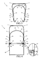
- FIGS 1, 2 and 3 a first embodiment of the gripping device according to the invention is shown in a side-view with the handle in different positions.
- the gripping device 1 has a U-shaped grip 3 made out of one piece of an elastic material, for example plastic, with a middle section 5 that is provided with a handgrip 7 and two flexible arms 9, 11.
- the free outer ends 13, 15 of the arms 9, 11 are made as hook-shaped parts 17, 19 with the openings 21, 23 turned outwards and which are a means of coupling for coupling to a paint tin in such a way that it is detachable.
- the gripping device 1 has a means of moving with which the arms can be moved in a direction towards each other.
- This means of moving is made up of a U-shaped handle 25 with a middle section 27 and two legs 29, 31 which are connected to it.
- This handle 25 is situated between the arms of the grip 3, where the handle's middle section 27 is situated at a distance from, but is near the grip's middle section 5.
- the free outer ends 33, 35 of the handle's legs are provided with sleeves 37, 39 which are situated on the arms 9, 11 of the grip 3 and can be slid along those arms.
- the arms 9, 11 of the grip 3 are provided with stops 45, 47 which limit sliding of the free outer ends 33, 35 of the handle's legs in a direction P towards the middle section 5 of the grip, see figure 2 .
- the arms 9, 11 bend as a result of which the free outer ends 13, 15 of the arms come towards each other, see figure 3 .
- the gripping device 1 is shown once again but now on a paint tin 49.
- the hook-shaped parts 17, 19 are situated here about the rim 48 of a paint tin 49, which rim projects inwards, and the locking elements 41, 43 are situated on the exterior side of the paint tin 49 and close off the rim 48.
- the locking elements 41, 43 on the side turned toward the grip 3 preferably are provided with an opening 42, 44 (see figures 1- 3 also) for receiving an outward projecting rim 48b on the periphery at the top of the tin of paint when the gripping device 1 fitted on the paint tin. Because of this, the locking elements are clicked in the locked position on the rim 48b of the tin and more force is needed to pull the locking elements up into the unlocked position.
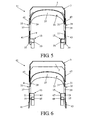
- FIG 5 a second embodiment of the gripping device 51 according to the invention is shown in perspective. All parts of this gripping device 51 that are the same as those in the drawings of the gripping device 1 shown in figures 1- 4 , are indicated by the same reference number.
- This gripping device 51 is provided with hooks 53, 55 with a larger opening 57, 59 for use on paint tins with a thicker rim.
- a third embodiment of the gripping device 61 is shown in figure 6 .
- FIG 7 a fourth embodiment of the gripping device 81 is shown in perspective on a paint tin 83.
- the handle 85 of this gripping device 81 is provided with an opening 87 in the middle of which a brush 89 can be hung.
Landscapes
- Engineering & Computer Science (AREA)
- Mechanical Engineering (AREA)
- Details Of Rigid Or Semi-Rigid Containers (AREA)
- Coating Apparatus (AREA)
- Spray Control Apparatus (AREA)
- Catching Or Destruction (AREA)
Claims (9)
- Poignée (1; 61; 81) à fixer à un récipient de peinture (49; 83), en particulier un pot de peinture, comprenant un premier élément en U formant une prise (3) avec une partie centrale (5) formant une prise (7) reliée à deux bras (9, 11), dont les extrémités libres sont dotées de dispositifs d'accouplement pour un accouplement amovible avec un récipient de peinture, où au moins les extrémités libres (13, 15) des bras sont mobiles par rapport à la partie centrale, laquelle poignée comprend des dispositifs de déplacement pour rapprocher les extrémités libres (13, 15) des bras dans un sens, caractérisés en ce que les dispositifs de déplacement sont formés d'un deuxième élément en U qui forme un levier (25) avec une partie centrale (27) reliée à deux pieds (29, 31), lequel levier se situe entre les bras (9, 11) du collier, où la partie centrale (27) du levier se trouve près de la partie centrale (5) du collier, et où les extrémités libres (33, 35) des pieds du levier sont accouplés aux bras (9, 11) du collier.
- Poignée (1; 61; 81) selon la revendication 1, caractérisée en ce que les extrémités libres (33, 35) des pieds (29, 31) du levier sont fixées aux bras (9, 11) du collier.
- Poignée (1; 61; 81) selon la revendication 2, caractérisée en ce que les extrémités libres (33, 35) des pieds (29, 31) du levier sont coulissants le long des bras (9, 11) du collier, et les bras du collier sont dotés de butées (45, 47) qui limitent le déplacement des extrémités libres des pieds du levier dans un sens (P) vers la partie centrale du collier.
- Poignée (1; 61; 81) selon l'une des revendications précédentes, caractérisée en ce que chaque extrémité libre (13, 15) des bras (9, 11) du collier est dotée d'une pièce en forme de crochet (17, 19; 63, 65) qui fait partie des dispositifs d'accouplement, où le crochet avec l'ouverture (21, 23; 71, 73) est tourné vers l'extérieur.
- Poignée (61) selon la revendication 4, caractérisée en ce que chaque extrémité libre (13, 15) des bras (9, 11) du collier, outre la pièce en forme de crochet, est dotée d'une autre pièce en forme de crochet (65, 69) d'une autre dimension que la pièce en forme de crochet citée.
- Poignée (1; 61; 81) selon la revendication 4 ou 5, caractérisée en ce qu'elle comprend également deux éléments de verrouillage (41, 43) pouvant être amenés devant les ouvertures (21, 23; 71, 73, 75, 77) des pièces en forme de crochet (17, 19; 63, 65,67,69).
- Poignée (1; 61; 81) selon les revendications 3 et 6, caractérisée en ce que les éléments de verrouillage (41, 43) sont fixés aux extrémités libres (33, 35) des pieds (29, 31) du levier.
- Poignée (1; 61; 81) selon la revendication 6 ou 7, caractérisée en ce que les éléments de verrouillage (41, 43) sont formés de bandes de verrouillage coulissantes le long des bras (9, 11) du collier.
- Poignée (1; 61; 81) selon l'une des revendications précédentes de 6 à 8 comprise, caractérisée en ce que les éléments de verrouillage (41, 43) sont dotés du côté tourné vers le collier d'une découpe (42, 44) pour l'insertion d'un bord orienté vers l'extérieur (48b) à la périphérie supérieure d'un pot de peinture en posant la poignée sur un pot de peinture.
Applications Claiming Priority (4)
| Application Number | Priority Date | Filing Date | Title |
|---|---|---|---|
| NL1026162 | 2004-05-11 | ||
| NL1026353A NL1026353C2 (nl) | 2004-05-11 | 2004-06-08 | Hengel voor aan een verfhouder, in het bijzonder een verfblik. |
| NL1026965 | 2004-09-03 | ||
| PCT/NL2005/000359 WO2005108221A2 (fr) | 2004-05-11 | 2005-05-11 | Dispositif de prehension utilise sur un support de peinture, en particulier une boite de peinture |
Publications (2)
| Publication Number | Publication Date |
|---|---|
| EP1753667A2 EP1753667A2 (fr) | 2007-02-21 |
| EP1753667B1 true EP1753667B1 (fr) | 2011-04-27 |
Family
ID=35320773
Family Applications (1)
| Application Number | Title | Priority Date | Filing Date |
|---|---|---|---|
| EP05745758A Expired - Lifetime EP1753667B1 (fr) | 2004-05-11 | 2005-05-11 | Dispositif de prehension utilise sur un support de peinture, en particulier une boite de peinture |
Country Status (7)
| Country | Link |
|---|---|
| US (1) | US7520547B2 (fr) |
| EP (1) | EP1753667B1 (fr) |
| AT (1) | ATE507155T1 (fr) |
| CA (1) | CA2608131A1 (fr) |
| DE (1) | DE602005027691D1 (fr) |
| NL (1) | NL1026353C2 (fr) |
| WO (1) | WO2005108221A2 (fr) |
Families Citing this family (9)
| Publication number | Priority date | Publication date | Assignee | Title |
|---|---|---|---|---|
| FI20060724A0 (fi) * | 2006-08-10 | 2006-08-10 | Pekka Tapani Huttunen | Säiliön kahva |
| US20110210126A1 (en) * | 2010-02-26 | 2011-09-01 | Terry Vovan | Food container attachable to cup |
| USD643697S1 (en) * | 2010-07-08 | 2011-08-23 | Hearthmark, Llc | Canning lifter |
| US20120019017A1 (en) * | 2010-07-21 | 2012-01-26 | Ism Industries Llc | Multi-configuration Plant Pot Holder and Handle |
| US20120055583A1 (en) * | 2010-09-08 | 2012-03-08 | Schnatter John H | Sauce Leveler Device |
| CN102059689B (zh) * | 2010-10-27 | 2012-05-23 | 吴成芳 | 一种简易热厨具取放机械手 |
| USD788540S1 (en) | 2015-11-10 | 2017-06-06 | Dennis Mock | Belt for a carrying a cooking pot and lid |
| US10472130B2 (en) * | 2015-12-03 | 2019-11-12 | Norman Foster | Bucket handle assembly |
| WO2023242734A1 (fr) * | 2022-06-14 | 2023-12-21 | V'ice Bv | Dispositif de levage de plateau à crème glacée |
Family Cites Families (12)
| Publication number | Priority date | Publication date | Assignee | Title |
|---|---|---|---|---|
| US424913A (en) * | 1890-04-01 | Plate-lifter | ||
| US912472A (en) * | 1907-08-02 | 1909-02-16 | George B Hart | Detachable bail for flower-pots and like articles. |
| US1349457A (en) * | 1917-03-03 | 1920-08-10 | Enos A Hurd | Lifting-handle for storage batteries |
| US1716849A (en) * | 1928-09-14 | 1929-06-11 | William E Culp | Can lifter |
| US2628858A (en) * | 1947-02-18 | 1953-02-17 | William J Doty | Detachable bail-shaped handle for rimmed cans |
| FR974500A (fr) * | 1948-11-03 | 1951-02-22 | Joyaux Aine Et Cie Ets | Anse amovible |
| US4023702A (en) * | 1976-06-14 | 1977-05-17 | Mcknight Virgil L | Paint tray handle and roller support |
| DE3200889A1 (de) * | 1981-06-03 | 1983-01-05 | Fluoroware, Inc., Chaska, Minn. | "loesbarer handgriff fuer einen korb zur aufnahme von siliciumscheiben" |
| DE9309975U1 (de) * | 1993-07-05 | 1993-09-30 | Eckert, Harald, 74679 Weißbach | Handtragevorrichtung für Getränkekisten |
| DE29519786U1 (de) * | 1995-12-13 | 1996-01-25 | Rogge, Karlheinz, 74638 Waldenburg | Griffeinrichtung |
| US6431392B1 (en) * | 1999-08-06 | 2002-08-13 | Donald G. Eisenbeisz | Adjustable paint tray carrier apparatus and method |
| CA2642725A1 (fr) * | 2005-02-15 | 2006-08-24 | Rudolphus Johannes Adrianus Maria Cornelissen | Bac de rouleau a peindre avec deux surfaces de roulage |
-
2004
- 2004-06-08 NL NL1026353A patent/NL1026353C2/nl not_active IP Right Cessation
-
2005
- 2005-05-11 CA CA002608131A patent/CA2608131A1/fr not_active Abandoned
- 2005-05-11 EP EP05745758A patent/EP1753667B1/fr not_active Expired - Lifetime
- 2005-05-11 WO PCT/NL2005/000359 patent/WO2005108221A2/fr not_active Ceased
- 2005-05-11 AT AT05745758T patent/ATE507155T1/de not_active IP Right Cessation
- 2005-05-11 DE DE602005027691T patent/DE602005027691D1/de not_active Expired - Lifetime
-
2006
- 2006-11-10 US US11/595,678 patent/US7520547B2/en not_active Expired - Fee Related
Also Published As
| Publication number | Publication date |
|---|---|
| DE602005027691D1 (de) | 2011-06-09 |
| NL1026353C2 (nl) | 2005-11-15 |
| ATE507155T1 (de) | 2011-05-15 |
| US7520547B2 (en) | 2009-04-21 |
| WO2005108221A2 (fr) | 2005-11-17 |
| EP1753667A2 (fr) | 2007-02-21 |
| CA2608131A1 (fr) | 2005-11-17 |
| US20070114807A1 (en) | 2007-05-24 |
| WO2005108221A3 (fr) | 2006-04-13 |
Similar Documents
| Publication | Publication Date | Title |
|---|---|---|
| US7086676B2 (en) | Multi-purpose tongs having an incremental cam | |
| EP1753667B1 (fr) | Dispositif de prehension utilise sur un support de peinture, en particulier une boite de peinture | |
| US5704092A (en) | Removable handle for containers | |
| US20190138052A1 (en) | Interchangeable socket accessory for a portable electronic device | |
| US6503019B1 (en) | Replaceable top tube for bicycles | |
| JP4391946B2 (ja) | ロック可能なトング | |
| EP0801898A1 (fr) | Moule démontable pour gateaux | |
| US9607259B2 (en) | Tag housing asembly for attachment to a bottle neck | |
| US5772582A (en) | Nasal speculum | |
| JP2002542439A (ja) | エネルギー案内チェーン | |
| US20160045053A1 (en) | Detachable Pivoting Handle For Gripping a Cookware Vessel | |
| US11038305B1 (en) | Electrical cord connector for securing two electrical cords connected to one another | |
| US6117588A (en) | Detachable battery handle assembly | |
| EP2327344A1 (fr) | Anse à protection thermique destinée à un récipient de cuisson | |
| EP1486115A1 (fr) | Mangeoire pour oiseaux | |
| US20080000671A1 (en) | Cable bundle clamp with two opposing spring-loaded hinged shells | |
| US8875930B2 (en) | Emesis container | |
| US20050006389A1 (en) | Container tab | |
| US20060162128A1 (en) | Removable gripping handle for grilling tools | |
| WO2018140666A1 (fr) | Étui à clés | |
| US20040056492A1 (en) | Reaching apparatus kit and method of using same | |
| EP1358796A1 (fr) | Accessoire de pêche | |
| US10193264B1 (en) | Outlet cover | |
| CN111225586A (zh) | 容器设备和容器安装颈式联结装置 | |
| EP1440876A1 (fr) | Tube horizontal interchangeable pour bicyclette |
Legal Events
| Date | Code | Title | Description |
|---|---|---|---|
| PUAI | Public reference made under article 153(3) epc to a published international application that has entered the european phase |
Free format text: ORIGINAL CODE: 0009012 |
|
| 17P | Request for examination filed |
Effective date: 20061211 |
|
| AK | Designated contracting states |
Kind code of ref document: A2 Designated state(s): AT BE BG CH CY CZ DE DK EE ES FI FR GB GR HU IE IS IT LI LT LU MC NL PL PT RO SE SI SK TR |
|
| DAX | Request for extension of the european patent (deleted) | ||
| 17Q | First examination report despatched |
Effective date: 20090514 |
|
| GRAP | Despatch of communication of intention to grant a patent |
Free format text: ORIGINAL CODE: EPIDOSNIGR1 |
|
| GRAS | Grant fee paid |
Free format text: ORIGINAL CODE: EPIDOSNIGR3 |
|
| GRAA | (expected) grant |
Free format text: ORIGINAL CODE: 0009210 |
|
| AK | Designated contracting states |
Kind code of ref document: B1 Designated state(s): AT BE BG CH CY CZ DE DK EE ES FI FR GB GR HU IE IS IT LI LT LU MC NL PL PT RO SE SI SK TR |
|
| REG | Reference to a national code |
Ref country code: GB Ref legal event code: FG4D |
|
| REG | Reference to a national code |
Ref country code: CH Ref legal event code: EP |
|
| REG | Reference to a national code |
Ref country code: IE Ref legal event code: FG4D |
|
| RAP2 | Party data changed (patent owner data changed or rights of a patent transferred) |
Owner name: VAN DEN BOOM, MARCUS CAROLUS ADRIANUS Owner name: VERHEES, GODEFRIDUS JOSEPHUS MARIA |
|
| REF | Corresponds to: |
Ref document number: 602005027691 Country of ref document: DE Date of ref document: 20110609 Kind code of ref document: P |
|
| REG | Reference to a national code |
Ref country code: DE Ref legal event code: R096 Ref document number: 602005027691 Country of ref document: DE Effective date: 20110609 |
|
| REG | Reference to a national code |
Ref country code: NL Ref legal event code: T3 |
|
| LTIE | Lt: invalidation of european patent or patent extension |
Effective date: 20110427 |
|
| PG25 | Lapsed in a contracting state [announced via postgrant information from national office to epo] |
Ref country code: SE Free format text: LAPSE BECAUSE OF FAILURE TO SUBMIT A TRANSLATION OF THE DESCRIPTION OR TO PAY THE FEE WITHIN THE PRESCRIBED TIME-LIMIT Effective date: 20110427 Ref country code: PT Free format text: LAPSE BECAUSE OF FAILURE TO SUBMIT A TRANSLATION OF THE DESCRIPTION OR TO PAY THE FEE WITHIN THE PRESCRIBED TIME-LIMIT Effective date: 20110829 Ref country code: LT Free format text: LAPSE BECAUSE OF FAILURE TO SUBMIT A TRANSLATION OF THE DESCRIPTION OR TO PAY THE FEE WITHIN THE PRESCRIBED TIME-LIMIT Effective date: 20110427 |
|
| PGFP | Annual fee paid to national office [announced via postgrant information from national office to epo] |
Ref country code: FR Payment date: 20110805 Year of fee payment: 7 |
|
| PG25 | Lapsed in a contracting state [announced via postgrant information from national office to epo] |
Ref country code: GR Free format text: LAPSE BECAUSE OF FAILURE TO SUBMIT A TRANSLATION OF THE DESCRIPTION OR TO PAY THE FEE WITHIN THE PRESCRIBED TIME-LIMIT Effective date: 20110728 Ref country code: FI Free format text: LAPSE BECAUSE OF FAILURE TO SUBMIT A TRANSLATION OF THE DESCRIPTION OR TO PAY THE FEE WITHIN THE PRESCRIBED TIME-LIMIT Effective date: 20110427 Ref country code: AT Free format text: LAPSE BECAUSE OF FAILURE TO SUBMIT A TRANSLATION OF THE DESCRIPTION OR TO PAY THE FEE WITHIN THE PRESCRIBED TIME-LIMIT Effective date: 20110427 Ref country code: IS Free format text: LAPSE BECAUSE OF FAILURE TO SUBMIT A TRANSLATION OF THE DESCRIPTION OR TO PAY THE FEE WITHIN THE PRESCRIBED TIME-LIMIT Effective date: 20110827 Ref country code: SI Free format text: LAPSE BECAUSE OF FAILURE TO SUBMIT A TRANSLATION OF THE DESCRIPTION OR TO PAY THE FEE WITHIN THE PRESCRIBED TIME-LIMIT Effective date: 20110427 Ref country code: BE Free format text: LAPSE BECAUSE OF FAILURE TO SUBMIT A TRANSLATION OF THE DESCRIPTION OR TO PAY THE FEE WITHIN THE PRESCRIBED TIME-LIMIT Effective date: 20110427 Ref country code: ES Free format text: LAPSE BECAUSE OF FAILURE TO SUBMIT A TRANSLATION OF THE DESCRIPTION OR TO PAY THE FEE WITHIN THE PRESCRIBED TIME-LIMIT Effective date: 20110807 Ref country code: CY Free format text: LAPSE BECAUSE OF FAILURE TO SUBMIT A TRANSLATION OF THE DESCRIPTION OR TO PAY THE FEE WITHIN THE PRESCRIBED TIME-LIMIT Effective date: 20110427 |
|
| PGFP | Annual fee paid to national office [announced via postgrant information from national office to epo] |
Ref country code: GB Payment date: 20110721 Year of fee payment: 7 Ref country code: DE Payment date: 20110712 Year of fee payment: 7 |
|
| PG25 | Lapsed in a contracting state [announced via postgrant information from national office to epo] |
Ref country code: MC Free format text: LAPSE BECAUSE OF NON-PAYMENT OF DUE FEES Effective date: 20110531 |
|
| PGFP | Annual fee paid to national office [announced via postgrant information from national office to epo] |
Ref country code: NL Payment date: 20110719 Year of fee payment: 7 |
|
| REG | Reference to a national code |
Ref country code: CH Ref legal event code: PL |
|
| PG25 | Lapsed in a contracting state [announced via postgrant information from national office to epo] |
Ref country code: CZ Free format text: LAPSE BECAUSE OF FAILURE TO SUBMIT A TRANSLATION OF THE DESCRIPTION OR TO PAY THE FEE WITHIN THE PRESCRIBED TIME-LIMIT Effective date: 20110427 Ref country code: EE Free format text: LAPSE BECAUSE OF FAILURE TO SUBMIT A TRANSLATION OF THE DESCRIPTION OR TO PAY THE FEE WITHIN THE PRESCRIBED TIME-LIMIT Effective date: 20110427 Ref country code: CH Free format text: LAPSE BECAUSE OF NON-PAYMENT OF DUE FEES Effective date: 20110531 Ref country code: LI Free format text: LAPSE BECAUSE OF NON-PAYMENT OF DUE FEES Effective date: 20110531 |
|
| PG25 | Lapsed in a contracting state [announced via postgrant information from national office to epo] |
Ref country code: PL Free format text: LAPSE BECAUSE OF FAILURE TO SUBMIT A TRANSLATION OF THE DESCRIPTION OR TO PAY THE FEE WITHIN THE PRESCRIBED TIME-LIMIT Effective date: 20110427 Ref country code: RO Free format text: LAPSE BECAUSE OF FAILURE TO SUBMIT A TRANSLATION OF THE DESCRIPTION OR TO PAY THE FEE WITHIN THE PRESCRIBED TIME-LIMIT Effective date: 20110427 Ref country code: DK Free format text: LAPSE BECAUSE OF FAILURE TO SUBMIT A TRANSLATION OF THE DESCRIPTION OR TO PAY THE FEE WITHIN THE PRESCRIBED TIME-LIMIT Effective date: 20110427 Ref country code: SK Free format text: LAPSE BECAUSE OF FAILURE TO SUBMIT A TRANSLATION OF THE DESCRIPTION OR TO PAY THE FEE WITHIN THE PRESCRIBED TIME-LIMIT Effective date: 20110427 |
|
| REG | Reference to a national code |
Ref country code: IE Ref legal event code: MM4A |
|
| PLBE | No opposition filed within time limit |
Free format text: ORIGINAL CODE: 0009261 |
|
| STAA | Information on the status of an ep patent application or granted ep patent |
Free format text: STATUS: NO OPPOSITION FILED WITHIN TIME LIMIT |
|
| 26N | No opposition filed |
Effective date: 20120130 |
|
| PG25 | Lapsed in a contracting state [announced via postgrant information from national office to epo] |
Ref country code: IE Free format text: LAPSE BECAUSE OF NON-PAYMENT OF DUE FEES Effective date: 20110511 |
|
| REG | Reference to a national code |
Ref country code: DE Ref legal event code: R097 Ref document number: 602005027691 Country of ref document: DE Effective date: 20120130 |
|
| PG25 | Lapsed in a contracting state [announced via postgrant information from national office to epo] |
Ref country code: IT Free format text: LAPSE BECAUSE OF FAILURE TO SUBMIT A TRANSLATION OF THE DESCRIPTION OR TO PAY THE FEE WITHIN THE PRESCRIBED TIME-LIMIT Effective date: 20110427 |
|
| REG | Reference to a national code |
Ref country code: NL Ref legal event code: V1 Effective date: 20121201 |
|
| GBPC | Gb: european patent ceased through non-payment of renewal fee |
Effective date: 20120511 |
|
| REG | Reference to a national code |
Ref country code: FR Ref legal event code: ST Effective date: 20130131 |
|
| REG | Reference to a national code |
Ref country code: DE Ref legal event code: R119 Ref document number: 602005027691 Country of ref document: DE Effective date: 20121201 |
|
| PG25 | Lapsed in a contracting state [announced via postgrant information from national office to epo] |
Ref country code: NL Free format text: LAPSE BECAUSE OF NON-PAYMENT OF DUE FEES Effective date: 20121201 |
|
| PG25 | Lapsed in a contracting state [announced via postgrant information from national office to epo] |
Ref country code: FR Free format text: LAPSE BECAUSE OF NON-PAYMENT OF DUE FEES Effective date: 20120531 Ref country code: GB Free format text: LAPSE BECAUSE OF NON-PAYMENT OF DUE FEES Effective date: 20120511 |
|
| PG25 | Lapsed in a contracting state [announced via postgrant information from national office to epo] |
Ref country code: LU Free format text: LAPSE BECAUSE OF NON-PAYMENT OF DUE FEES Effective date: 20110511 |
|
| PG25 | Lapsed in a contracting state [announced via postgrant information from national office to epo] |
Ref country code: BG Free format text: LAPSE BECAUSE OF FAILURE TO SUBMIT A TRANSLATION OF THE DESCRIPTION OR TO PAY THE FEE WITHIN THE PRESCRIBED TIME-LIMIT Effective date: 20110727 Ref country code: DE Free format text: LAPSE BECAUSE OF NON-PAYMENT OF DUE FEES Effective date: 20121201 |
|
| PG25 | Lapsed in a contracting state [announced via postgrant information from national office to epo] |
Ref country code: TR Free format text: LAPSE BECAUSE OF FAILURE TO SUBMIT A TRANSLATION OF THE DESCRIPTION OR TO PAY THE FEE WITHIN THE PRESCRIBED TIME-LIMIT Effective date: 20110427 |
|
| PG25 | Lapsed in a contracting state [announced via postgrant information from national office to epo] |
Ref country code: HU Free format text: LAPSE BECAUSE OF FAILURE TO SUBMIT A TRANSLATION OF THE DESCRIPTION OR TO PAY THE FEE WITHIN THE PRESCRIBED TIME-LIMIT Effective date: 20110427 |