EP1753665B1 - Composite cardboard can - Google Patents
Composite cardboard can Download PDFInfo
- Publication number
- EP1753665B1 EP1753665B1 EP05748413A EP05748413A EP1753665B1 EP 1753665 B1 EP1753665 B1 EP 1753665B1 EP 05748413 A EP05748413 A EP 05748413A EP 05748413 A EP05748413 A EP 05748413A EP 1753665 B1 EP1753665 B1 EP 1753665B1
- Authority
- EP
- European Patent Office
- Prior art keywords
- sleeve
- opening edge
- lid
- container according
- laminated cardboard
- Prior art date
- Legal status (The legal status is an assumption and is not a legal conclusion. Google has not performed a legal analysis and makes no representation as to the accuracy of the status listed.)
- Expired - Lifetime
Links
Images
Classifications
-
- B—PERFORMING OPERATIONS; TRANSPORTING
- B65—CONVEYING; PACKING; STORING; HANDLING THIN OR FILAMENTARY MATERIAL
- B65D—CONTAINERS FOR STORAGE OR TRANSPORT OF ARTICLES OR MATERIALS, e.g. BAGS, BARRELS, BOTTLES, BOXES, CANS, CARTONS, CRATES, DRUMS, JARS, TANKS, HOPPERS, FORWARDING CONTAINERS; ACCESSORIES, CLOSURES, OR FITTINGS THEREFOR; PACKAGING ELEMENTS; PACKAGES
- B65D3/00—Rigid or semi-rigid containers having bodies or peripheral walls of curved or partially-curved cross-section made by winding or bending paper without folding along defined lines
- B65D3/28—Other details of walls
- B65D3/30—Local reinforcements, e.g. metallic rims
-
- B—PERFORMING OPERATIONS; TRANSPORTING
- B65—CONVEYING; PACKING; STORING; HANDLING THIN OR FILAMENTARY MATERIAL
- B65D—CONTAINERS FOR STORAGE OR TRANSPORT OF ARTICLES OR MATERIALS, e.g. BAGS, BARRELS, BOTTLES, BOXES, CANS, CARTONS, CRATES, DRUMS, JARS, TANKS, HOPPERS, FORWARDING CONTAINERS; ACCESSORIES, CLOSURES, OR FITTINGS THEREFOR; PACKAGING ELEMENTS; PACKAGES
- B65D43/00—Lids or covers for rigid or semi-rigid containers
- B65D43/02—Removable lids or covers
- B65D43/0235—Removable lids or covers with integral tamper element
- B65D43/0237—Removable lids or covers with integral tamper element secured by snapping over beads or projections before removal of the tamper element
- B65D43/0256—Removable lids or covers with integral tamper element secured by snapping over beads or projections before removal of the tamper element only on the outside, or a part turned to the outside, of the mouth of the container
- B65D43/026—Removable lids or covers with integral tamper element secured by snapping over beads or projections before removal of the tamper element only on the outside, or a part turned to the outside, of the mouth of the container leaving only an inside friction after removal of the tamper element
-
- B—PERFORMING OPERATIONS; TRANSPORTING
- B65—CONVEYING; PACKING; STORING; HANDLING THIN OR FILAMENTARY MATERIAL
- B65D—CONTAINERS FOR STORAGE OR TRANSPORT OF ARTICLES OR MATERIALS, e.g. BAGS, BARRELS, BOTTLES, BOXES, CANS, CARTONS, CRATES, DRUMS, JARS, TANKS, HOPPERS, FORWARDING CONTAINERS; ACCESSORIES, CLOSURES, OR FITTINGS THEREFOR; PACKAGING ELEMENTS; PACKAGES
- B65D51/00—Closures not otherwise provided for
- B65D51/18—Arrangements of closures with protective outer cap-like covers or of two or more co-operating closures
- B65D51/20—Caps, lids, or covers co-operating with an inner closure arranged to be opened by piercing, cutting, or tearing
-
- B—PERFORMING OPERATIONS; TRANSPORTING
- B65—CONVEYING; PACKING; STORING; HANDLING THIN OR FILAMENTARY MATERIAL
- B65D—CONTAINERS FOR STORAGE OR TRANSPORT OF ARTICLES OR MATERIALS, e.g. BAGS, BARRELS, BOTTLES, BOXES, CANS, CARTONS, CRATES, DRUMS, JARS, TANKS, HOPPERS, FORWARDING CONTAINERS; ACCESSORIES, CLOSURES, OR FITTINGS THEREFOR; PACKAGING ELEMENTS; PACKAGES
- B65D2543/00—Lids or covers essentially for box-like containers
- B65D2543/00009—Details of lids or covers for rigid or semi-rigid containers
- B65D2543/00018—Overall construction of the lid
- B65D2543/00064—Shape of the outer periphery
- B65D2543/00074—Shape of the outer periphery curved
- B65D2543/00092—Shape of the outer periphery curved circular
-
- B—PERFORMING OPERATIONS; TRANSPORTING
- B65—CONVEYING; PACKING; STORING; HANDLING THIN OR FILAMENTARY MATERIAL
- B65D—CONTAINERS FOR STORAGE OR TRANSPORT OF ARTICLES OR MATERIALS, e.g. BAGS, BARRELS, BOTTLES, BOXES, CANS, CARTONS, CRATES, DRUMS, JARS, TANKS, HOPPERS, FORWARDING CONTAINERS; ACCESSORIES, CLOSURES, OR FITTINGS THEREFOR; PACKAGING ELEMENTS; PACKAGES
- B65D2543/00—Lids or covers essentially for box-like containers
- B65D2543/00009—Details of lids or covers for rigid or semi-rigid containers
- B65D2543/00018—Overall construction of the lid
- B65D2543/00259—Materials used
- B65D2543/00296—Plastic
-
- B—PERFORMING OPERATIONS; TRANSPORTING
- B65—CONVEYING; PACKING; STORING; HANDLING THIN OR FILAMENTARY MATERIAL
- B65D—CONTAINERS FOR STORAGE OR TRANSPORT OF ARTICLES OR MATERIALS, e.g. BAGS, BARRELS, BOTTLES, BOXES, CANS, CARTONS, CRATES, DRUMS, JARS, TANKS, HOPPERS, FORWARDING CONTAINERS; ACCESSORIES, CLOSURES, OR FITTINGS THEREFOR; PACKAGING ELEMENTS; PACKAGES
- B65D2543/00—Lids or covers essentially for box-like containers
- B65D2543/00009—Details of lids or covers for rigid or semi-rigid containers
- B65D2543/00444—Contact between the container and the lid
- B65D2543/00481—Contact between the container and the lid on the inside or the outside of the container
- B65D2543/0049—Contact between the container and the lid on the inside or the outside of the container on the inside, or a part turned to the inside of the mouth of the container
- B65D2543/00509—Cup
-
- B—PERFORMING OPERATIONS; TRANSPORTING
- B65—CONVEYING; PACKING; STORING; HANDLING THIN OR FILAMENTARY MATERIAL
- B65D—CONTAINERS FOR STORAGE OR TRANSPORT OF ARTICLES OR MATERIALS, e.g. BAGS, BARRELS, BOTTLES, BOXES, CANS, CARTONS, CRATES, DRUMS, JARS, TANKS, HOPPERS, FORWARDING CONTAINERS; ACCESSORIES, CLOSURES, OR FITTINGS THEREFOR; PACKAGING ELEMENTS; PACKAGES
- B65D2543/00—Lids or covers essentially for box-like containers
- B65D2543/00009—Details of lids or covers for rigid or semi-rigid containers
- B65D2543/00444—Contact between the container and the lid
- B65D2543/00481—Contact between the container and the lid on the inside or the outside of the container
- B65D2543/00537—Contact between the container and the lid on the inside or the outside of the container on the outside, or a part turned to the outside of the mouth of the container
- B65D2543/00546—NO contact
-
- B—PERFORMING OPERATIONS; TRANSPORTING
- B65—CONVEYING; PACKING; STORING; HANDLING THIN OR FILAMENTARY MATERIAL
- B65D—CONTAINERS FOR STORAGE OR TRANSPORT OF ARTICLES OR MATERIALS, e.g. BAGS, BARRELS, BOTTLES, BOXES, CANS, CARTONS, CRATES, DRUMS, JARS, TANKS, HOPPERS, FORWARDING CONTAINERS; ACCESSORIES, CLOSURES, OR FITTINGS THEREFOR; PACKAGING ELEMENTS; PACKAGES
- B65D2543/00—Lids or covers essentially for box-like containers
- B65D2543/00009—Details of lids or covers for rigid or semi-rigid containers
- B65D2543/00444—Contact between the container and the lid
- B65D2543/00481—Contact between the container and the lid on the inside or the outside of the container
- B65D2543/00555—Contact between the container and the lid on the inside or the outside of the container on both the inside and the outside
-
- B—PERFORMING OPERATIONS; TRANSPORTING
- B65—CONVEYING; PACKING; STORING; HANDLING THIN OR FILAMENTARY MATERIAL
- B65D—CONTAINERS FOR STORAGE OR TRANSPORT OF ARTICLES OR MATERIALS, e.g. BAGS, BARRELS, BOTTLES, BOXES, CANS, CARTONS, CRATES, DRUMS, JARS, TANKS, HOPPERS, FORWARDING CONTAINERS; ACCESSORIES, CLOSURES, OR FITTINGS THEREFOR; PACKAGING ELEMENTS; PACKAGES
- B65D2543/00—Lids or covers essentially for box-like containers
- B65D2543/00009—Details of lids or covers for rigid or semi-rigid containers
- B65D2543/00444—Contact between the container and the lid
- B65D2543/00592—Snapping means
- B65D2543/00601—Snapping means on the container
- B65D2543/00611—Profiles
- B65D2543/00638—Rolled edge
-
- B—PERFORMING OPERATIONS; TRANSPORTING
- B65—CONVEYING; PACKING; STORING; HANDLING THIN OR FILAMENTARY MATERIAL
- B65D—CONTAINERS FOR STORAGE OR TRANSPORT OF ARTICLES OR MATERIALS, e.g. BAGS, BARRELS, BOTTLES, BOXES, CANS, CARTONS, CRATES, DRUMS, JARS, TANKS, HOPPERS, FORWARDING CONTAINERS; ACCESSORIES, CLOSURES, OR FITTINGS THEREFOR; PACKAGING ELEMENTS; PACKAGES
- B65D2543/00—Lids or covers essentially for box-like containers
- B65D2543/00009—Details of lids or covers for rigid or semi-rigid containers
- B65D2543/00444—Contact between the container and the lid
- B65D2543/00592—Snapping means
- B65D2543/00601—Snapping means on the container
- B65D2543/00675—Periphery concerned
- B65D2543/00685—Totality
-
- B—PERFORMING OPERATIONS; TRANSPORTING
- B65—CONVEYING; PACKING; STORING; HANDLING THIN OR FILAMENTARY MATERIAL
- B65D—CONTAINERS FOR STORAGE OR TRANSPORT OF ARTICLES OR MATERIALS, e.g. BAGS, BARRELS, BOTTLES, BOXES, CANS, CARTONS, CRATES, DRUMS, JARS, TANKS, HOPPERS, FORWARDING CONTAINERS; ACCESSORIES, CLOSURES, OR FITTINGS THEREFOR; PACKAGING ELEMENTS; PACKAGES
- B65D2543/00—Lids or covers essentially for box-like containers
- B65D2543/00009—Details of lids or covers for rigid or semi-rigid containers
- B65D2543/00444—Contact between the container and the lid
- B65D2543/00592—Snapping means
- B65D2543/00712—Snapping means on the lid
- B65D2543/00722—Profiles
- B65D2543/0074—Massive bead
-
- B—PERFORMING OPERATIONS; TRANSPORTING
- B65—CONVEYING; PACKING; STORING; HANDLING THIN OR FILAMENTARY MATERIAL
- B65D—CONTAINERS FOR STORAGE OR TRANSPORT OF ARTICLES OR MATERIALS, e.g. BAGS, BARRELS, BOTTLES, BOXES, CANS, CARTONS, CRATES, DRUMS, JARS, TANKS, HOPPERS, FORWARDING CONTAINERS; ACCESSORIES, CLOSURES, OR FITTINGS THEREFOR; PACKAGING ELEMENTS; PACKAGES
- B65D2543/00—Lids or covers essentially for box-like containers
- B65D2543/00009—Details of lids or covers for rigid or semi-rigid containers
- B65D2543/00444—Contact between the container and the lid
- B65D2543/00592—Snapping means
- B65D2543/00712—Snapping means on the lid
- B65D2543/00787—Periphery concerned
- B65D2543/00796—Totality
-
- B—PERFORMING OPERATIONS; TRANSPORTING
- B65—CONVEYING; PACKING; STORING; HANDLING THIN OR FILAMENTARY MATERIAL
- B65D—CONTAINERS FOR STORAGE OR TRANSPORT OF ARTICLES OR MATERIALS, e.g. BAGS, BARRELS, BOTTLES, BOXES, CANS, CARTONS, CRATES, DRUMS, JARS, TANKS, HOPPERS, FORWARDING CONTAINERS; ACCESSORIES, CLOSURES, OR FITTINGS THEREFOR; PACKAGING ELEMENTS; PACKAGES
- B65D2543/00—Lids or covers essentially for box-like containers
- B65D2543/00009—Details of lids or covers for rigid or semi-rigid containers
- B65D2543/00824—Means for facilitating removing of the closure
- B65D2543/00833—Integral tabs, tongues, handles or similar
- B65D2543/00851—Integral tabs, tongues, handles or similar on the central part of the lid
Definitions
- the invention relates to a cardboard composite can with a sleeve made of paper or cardboard composite whose opening edge is formed at least one end to form at least three, at least partially substantially parallel layers of the sleeve material to the outside, wherein the free end of the sleeve having position between an inner layer and an outer layer is arranged.
- Cardboard composite cans are used in particular for receiving solid, optionally free-flowing or even fluid substances, for example foods or luxury foods, such as chips, coffee, biscuits, tobacco, etc.
- the lower part of the cardboard composite can formed from the sleeve and the bottom, and in particular the sleeve which forms the lateral surface of the cardboard composite can, consists of a paper or cardboard composite and generally carries an imprint characterizing the contents of the cardboard composite can.
- the sleeve of the cardboard composite can often has on its inside a lamination of a substantially gas-impermeable material, such as metal, plastic, metal-plastic Compounds or the like, on.
- a substantially gas-impermeable material such as metal, plastic, metal-plastic Compounds or the like
- the packaged cardboard composite cans which in the region of its opening edge by means of a membrane of gas impermeable material, such as metal, plastic or the like, gas-tight, in particular sealed, in order to further protection and a longer shelf life of the packaged goods and to protect the consumer from accidental or intentional damage or contamination of the packaged goods.
- a membrane seal is durably more or less completely removed during the first opening of the cardboard composite can, whereby a successful opening of the cardboard composite can be clearly seen.
- a lid on the opening edge of a can, which forms a so-called tamper-evident closure.
- the term "tamper-evident closure” refers to such a lid which is fixed to the opening edge of the can so that it as such can not be separated from the can without destroying the lid and / or the can that a first-opening of the box or a first-time removal of the lid is readily apparent.
- a disadvantage is that in the manner of a tamper-evident lid of the aforementioned type can be used only in cans made of glass, metal or plastic, since the undercut of the separable portion of the lid bulge of the can have in the region of its peripheral edge a certain stability and shape retention must, which can not be achieved in conventional cardboard cans so far.
- a cardboard composite can with an opening edge according to the preamble of claim 1 can be removed.
- the opening edge is thereby folded outwards so that three layers of the sleeve material are partially arranged approximately parallel and extending the free end of the sleeve having position between the inner and the outer layer.
- studies have shown even with such an opening edge that he has a sufficient to hold a lid designed in the form of a tamper only insufficient stability and the peripheral edge when pulling the lid up on or can unroll.
- the invention is therefore based on the object, the peripheral edge of a cardboard composite can with a sleeve of paper or cardboard composite form such that it is designed to functionally reliable arrangement of a tamper-evident lid, which opens the edge with a substantially parallel to the sleeve arranged, separable from the lid section engages outside locking, is in the situation.
- this object is achieved in a cardboard composite box of the type mentioned above in that the layers of the sleeve material in the area defined by the opening edge in the manner defined in claim 1 are pressed together.
- the embodiment of the invention gives the opening edge already when the opening edge of only three, at least partially approximately parallel layers is formed, a perfect dimensional stability, so that it gives a trained in the form of a tamper-evident lid of the above type a secure fit and a non-destructive The detachment of the same without reliably separating the section which engages under the invention according to the invention pressed along its weakening line.
- a winding or unrolling of the present invention pressed-in opening edge is prevented in particular by the arranged between at least one inner and at least one outer layer position with the free end of the sleeve material, which come to this parallel to the plant layers act like an abutment and reliably prevent unrolling of the opening edge.
- the cover peeled off with force, then it comes to at least partially ruptures of the lid and / or the sleeve material in the region or below the opening edge of the box, so that a first-time opening of the box is readily apparent and the lid in particular no longer then put the can on. Due to the at least three-layered design of the opening edge of this has, even if its layers have been compressed as a result of the compression, a sufficient thickness to the intervening him Section of the lid to give a secure and lasting hold.
- the inventively designed peripheral edge of the can is also advantageous if a lid designed in the form of a tamper-evident closure is not provided.
- a lid designed in the form of a tamper-evident closure is not provided.
- its high dimensional stability can be exploited in order to produce in the area of the opening edge by means of hot pressing tools on the inside, i.
- a sealing membrane which can be achieved due to the high stability of the opening edge over the prior art increased sealing pressures and thus reduced sealing times, resulting in increased productivity.
- the dimensional stability of the opening edge according to the invention is, moreover, so great that, in the case of the inner sealing of a sealing membrane, it is generally sufficient to move a hot sealing stamp into the interior of the can in the region of the peripheral edge, without the necessity of applying a back pressure from the outside, as is the case with prior art paperboard cans.
- the opening edge according to the invention also has the additional advantage that the free end having the position of the sleeve material between at least an inner and an outer layer is taken, so that on the one hand the cutting edge, which felt unaesthetic depending on the paper or cardboard material Fanning may have, is not visible and on the other hand - if the sleeve is provided with an inside lamination - can not come to a partial detachment of the lamination by mechanical stress in the region of the opening edge.
- the opening edge of course more than three, at least partially arranged approximately parallel, pressed together layers of the sleeve material, it is sufficient in most cases for perfect dimensional stability of the opening edge, if he exactly three, at least partially substantially parallel layers of the Sleeve material, wherein the free end of the sleeve having position between the inner and the outer layer of the sleeve material is arranged.
- the free end of the sleeve having position extends substantially over the entire height of the opening edge.
- these e.g. in the case of a three-layered design of the opening edge middle position of the sleeve with the free end on both sides, substantially over its entire extension adjacent adjacent layers as a result of their compression a reliable abutment to protect against unrolling of the peripheral edge and can be an optimal thickness of Opening edge with a very low compliance of the same along its entire extent achieve.
- the invention provides that the sum of the wall thicknesses of the substantially parallel layers of the opening edge as a result of compression is at most 80% of the sum of the wall thicknesses of a corresponding number of unpressed layers of the sleeve material
- the sum of the wall thicknesses of the substantially parallel layers of the opening edge as a result of the pressing preferably at most about 70%, in particular between about 60% and about 70%, the sum of the wall thicknesses can be a corresponding number of unpressed layers of the sleeve material.
- the lower bending edge of the opening edge extends substantially perpendicular to the sleeve, wherein preferably the inner and outer peripheral edge of the lower bending edge are formed substantially sharp-edged.
- the opening edge thus has a substantially rectangular profile, wherein the Umlegeadien the inner and the outer peripheral edge of the bending edge can be approximately 0.
- an optimal and highly stable, flat locking edge for the lid is formed, which is e.g. in a simple manner can be generated by the opening edge is supported at its lower, the lower bending edge forming end during the pressing of the layers against a forming die (calibration tool) as an abutment.
- the opening edge may be formed for reasons of a simple and cost-effective production to achieve a perfect stability in the form of an adhesive-free Preßharm the layers of the sleeve material.
- the sleeve can - if desired - have a particular over the opening edge with outwardly extending inner lining, as it is known as such in generic cardboard composite cans for protection against moisture, leaking odors and the like.
- the inner lining may preferably be made of a weldable material, such as a thermoplastic material, or contain such.
- the sleeve has a particular over the opening edge with outwardly extending outer coating and / or outer coating, wherein the outer coating or -lakk ist again preferably be formed of a weldable material or may contain such.
- the sleeve of the cardboard composite can is provided with such an inner lining and / or with such an outer coating or lacquering, it can further be provided that the inner lining of at least one layer in the region of the opening edge is welded to the outer coating or lacquering of at least one adjacent layer is what eg can be achieved in a simple manner by suitable pressure and temperature selection during the pressing of the layers of the sleeve material in the region of the opening edge.
- the free end of the sleeve having middle layer to be welded to the inner layer so that the greatest possible stability of the opening edge given and unrolling of the layers in the region of the opening edge de facto impossible.
- a simple - adhesive-free and not welding - pressing of the layers sufficient to achieve a sufficient and compared to the prior art, significantly increased stability of the opening edge.
- a tight-closing membrane is arranged on the inner lining in the region of the opening edge, wherein the membrane is preferably arranged sunk in the sleeve and exclusively is fixed with an annular, sleeve-parallel connection surface on the inner lining, in particular sealed to this, for example, to ensure a trouble-free arrangement of a formed in the form of a tamper-evident lid.
- such a membrane optionally provided with a tear-open tab, can also be dispensed with in the case of a corresponding design of the lid, if it rests in a substantially gas-tight manner even after the first removal from the can of the inner lining of the sleeve and thus ensures a satisfactory tightness of the can.
- a lid designed in the form of a tamper-evident closure engages over the opening edge with a section arranged essentially parallel to the sleeve, whereby the portion of the opening which engages under the opening edge of the sleeve Cover is separable along a line of weakness of the lid, so that the lid - after separating its the opening edge of the invention under cross-section along the line of weakness - is removable from the opening edge of the sleeve.
- the latter In addition to the opening edge of the sleeve engaging under the outside, detachable from the remaining lid portion of the lid, the latter preferably has a substantially parallel to the sleeve extending, the sleeve at least in the region of its opening edge on the inside adjacent portion over which the lid after separating the the opening edge on the outside under cross-section can be fixed to the opening edge of the sleeve.
- the outer diameter of the opening edge of the sleeve inside adjacent portion of the lid slightly exceeds, so that the lid after detachment of the opening edge outside under cross-section in the manner of a clamping connection to the opening edge of the sleeve is releasably fixed.
- a largely dense connection between the can and the lid can be achieved, in particular even after the first removal of the lid with separation of its opening edge of the box under the invention, the outer portion.
- the can generally has an opening edge of the aforementioned type arranged at the one end of the sleeve, while it is closed by a bottom at its end opposite the opening edge of the sleeve.
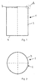
- a cardboard composite can 1 which has a shell 2 forming its lateral surface of a paper or cardboard composite material.
- the sleeve 2 has at its upper end a subsequently explained in more detail opening edge 3 and is at its the opening edge 3 opposite, in Fig. 1 bottom end provided with a bottom 4, which is fixed in any known manner on the sleeve 2.
- the sleeve 2 may be coated with an unspecified reproduced inner lining, for example of metal and / or plastic, which gives the sleeve 2 a perfect gas tightness.
- the bottom 4 in particular if this is likewise formed from a paper or cardboard composite material.
- the sleeve 2 may also be provided on the outside with an outer coating or coating, also not shown, which has, for example, a label identifying the contents of the can 1 or the like. While the sleeve 2 in the present embodiment has an approximately circular cross-section (see, in particular Fig. 2 ), this can of course also have an oval, polygonal or differently designed shape. It is also conceivable that the sleeve 2 instead of their rectilinear configuration according to Fig. 1 below the opening edge 3 has a narrowing from the bottom 4 upwards cross-section (not shown) to compensate for the given by the opening edge 3 cross-sectional widening and to allow a parallel arrangement of multiple cans 1 close to tight.
- the permanent and dimensionally stable opening edge 3 of the sleeve 2 is designed such that it is substantially parallel to form three arranged layers 2a, 2b, 2c is formed to the outside, wherein the layers 2a, 2b, 2c are pressed together and the free end 2d of the sleeve 2 having position 2b between the inner layer 2a and the outer layer 2c is arranged.
- the opening edge 3 of the sleeve 2 is in the present embodiment by folding the sleeve material in the region between the inner layer 2a and the outer layer 2c by approximately 180 ° radially outward (fold F 1 ) and by further folding of the sleeve material in the region between the outer layer 2c and the middle layer 2b formed by about 180 ° radially inwardly (fold F 2 ), the parallel layers 2a, 2b, 2c of the sleeve material in the region of the opening edge 3, in particular substantially over the entire height H, are pressed together so that the layers 2a, 2b, 2c at least in their central region - here practically parallel to each other over their entire area.
- the compression was carried out in the present embodiment such that such a plastic deformation or compression of the opening edge 3 forming layers 2a, 2b, 2c of the sleeve material has adjusted that the sum of the wall thicknesses D kompr of the substantially parallel layers 2a, 2b, 2c of the opening edge 3 or the total thickness of the opening edge 3 as a result of the pressing is about 75% of the sum of the wall thicknesses of a corresponding number of unpressed layers of the sleeve material.
- the middle layer 2b arranged between the inner layer 2a and the outer layer 2c with the free end 2d of the sleeve material extends substantially over the entire height H of the opening edge 3, ie from the upper fold F 1 to the lower fold F 2 , so that the free end 2 d of the middle layer 2 b is in the region of the arranged at the upper edge of the opening edge 3 fold F 1 , where the sleeve material to form the Inner layer 2a and the outer layer 2c is folded over by about 180 ° to the outside.
- the free end 2 d of the middle layer 2 b may be in contact with the inner layer 2 a and / or the outer layer 2 c in the region of the fold F 1 on its end face S.
- the press connection in this case is designed adhesive-free, with a perfect stability of the opening edge 3 is obtained, which - as already mentioned - in particular for receiving a below with reference to Fig. 4 lid is described in the form of a tamper evident closure suitable.
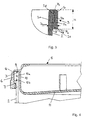
- Fig. 4 shows a detail section shown cut off by the cardboard composite can according to Fig. 1 to 3 in the region of its opening edge 3.
- the opening edge 3 according to Fig. 4 can one of the Fig. 3 have corresponding design, is in Fig. 4 however, for the sake of illustration only in the form of a thickening, in the region of which at least three approximately parallel layers 2a, 2b, 2c (FIG. FIG. 3 ) of the sleeve material are pressed together.
- the pressing pressure was chosen slightly higher in this case, so that the sum of the wall thicknesses D kompr of the substantially parallel layers 2a, 2b, 2c of the opening edge 3 or the total thickness of the same as a result of pressing about one third of the sum of the wall thicknesses of a corresponding number at unmolded layers of the sleeve material.
- a tamper-evident lid 5 is fixed, which may be made for example of a suitable plastic material.
- the lid 5 has a substantially parallel to the sleeve 2 arranged portion 6, which engages under the opening edge 3 of the sleeve 2 on the outside latching.
- the portion 6 of the lid 5 is provided in its sleeve facing inner, arranged below the opening edge 3 area with a locking projection 7, which prevents the lid 5 can be removed with the section 6 on the opening edge 3 away from the cardboard composite box.
- Both the portion 6 of the lid 5 and the locking projection 7 preferably extend over the entire circumference of the lid 5.
- the circumferential edge 3 of the sleeve 2 on the outside latching cross-section 6 of the lid 5 is a predetermined breaking or weakening line 8 of the lid 5 detachable, so that the lid 5 is removable only after separation of the section 6 along the line of weakness 8 of the can and the first-time opening is readily apparent.
- the inventive design of the opening edge 3 of the sleeve 2 gives this a sufficient stability and thickness to the designed in the form of a tamper-evident cover 5 at a can 1 (Fig. Fig. 1 ) can be used from paper or cardboard composite material.
- the line of weakness 8 between a radial on the in Fig. 4 upper end side of the opening edge 3 of the sleeve 2 seated portion 9 of the lid 5 and the portion 6 is arranged.
- a tab (not shown) may further be provided, which facilitates the manual gripping of the section 6 in order to separate it along the weakening line 8 from the remaining cover 5.
- the lid 5 is provided in the present embodiment with a substantially parallel to the sleeve 2 and to the portion 6 extending, the sleeve 2 at least in the region of the opening edge 3 inside adjacent section 10, via which the cover 5 after separation of the opening edge 3 outside under cross-section 6 on the sleeve 2 can be fixed.
- the section 10 in turn extends in particular around the entire peripheral region of the lid 5. While in the embodiment shown, the open-topped sleeve 2 covering, arranged substantially perpendicular to this section 11 at the portion 10, is recessed into the sleeve 2, this can Of course, be arranged above the opening edge 3 of the sleeve 2.
- a tight closing membrane (not shown), for example, metal, plastic, etc., be sealed, which is arranged sunken in the sleeve 2.
- Applicants.ist is preferably a central portion of the membrane along a line of weakness of the sleeve 2 on the inside fixed portion of the membrane, for example by means of a provided at the central portion of the membrane tear-open, detachable.
- the can body was by clamping between a stationary inner mandrel with a the inner cross section of the sleeve 2 approximately External cross-section and a stationary outer ring with an outer cross-section of the sleeve 2 approximately corresponding inner cross-section fixed.
- a lid 5 simulating metal ring was arranged and brought to the lower bending edge 2e and to the outer peripheral surface of the outer layer 2c for conditioning.
- the metal ring was moved by means of a pneumatic cylinder with about 100 mm diameter from the fixed sleeve 2 upwards, wherein the pressure in the pneumatic cylinder was measured. At a pressure of about 7 bar (corresponding to a withdrawal force of about 5000 N) tore the Material of the sleeve 2 below the opening edge 3 on; the opening edge 3 itself remained intact.
- the paper or paperboard composite edge of the invention has a more than seven times increased stability over a conventional opening edge, and in particular for receiving a lid, e.g. in the form of a tamper-evident closure, for sealing on the inside of a membrane without external support of the sleeve, etc., is outstandingly suitable.
Landscapes
- Engineering & Computer Science (AREA)
- Mechanical Engineering (AREA)
- Cartons (AREA)
- Packages (AREA)
- Laminated Bodies (AREA)
- Paper (AREA)
Abstract
Description
Die Erfindung betrifft eine Kartonverbunddose mit einer Hülse aus Papier- oder Kartonverbund, deren Öffnungsrand an wenigstens einem Ende unter Bildung von wenigstens drei, zumindest bereichsweise im wesentlichen parallel angeordneten Lagen des Hülsenmaterials nach außen umgeformt ist, wobei die das freie Ende der Hülse aufweisende Lage zwischen einer inneren Lage und einer äußeren Lage angeordnet ist.The invention relates to a cardboard composite can with a sleeve made of paper or cardboard composite whose opening edge is formed at least one end to form at least three, at least partially substantially parallel layers of the sleeve material to the outside, wherein the free end of the sleeve having position between an inner layer and an outer layer is arranged.
Kartonverbunddosen werden insbesondere zur Aufnahme von festen, gegebenenfalls rieselfähigen, oder auch fluiden Substanzen, beispielsweise Lebens- oder Genußmitteln, wie Chips, Kaffee, Kekse, Tabak etc., verwendet. Das aus Hülse und Boden gebildete Unterteil der Kartonverbunddose und insbesondere die die Mantelfläche der Kartonverbunddose bildende Hülse besteht aus Papier- oder Kartonverbund und trägt in der Regel einen den Inhalt der Kartonverbunddose kennzeichnenden Aufdruck.Cardboard composite cans are used in particular for receiving solid, optionally free-flowing or even fluid substances, for example foods or luxury foods, such as chips, coffee, biscuits, tobacco, etc. The lower part of the cardboard composite can formed from the sleeve and the bottom, and in particular the sleeve which forms the lateral surface of the cardboard composite can, consists of a paper or cardboard composite and generally carries an imprint characterizing the contents of the cardboard composite can.
Um den Inhalt der Kartonverbunddose vor äußeren Einflüssen, z.B. Feuchtigkeit, oder vor Substanzverlust, beispielsweise durch Austrocknen, zu schützen, weist die Hülse der Kartonverbunddose an ihrer Innenseite häufig eine Kaschierung aus einem im wesentlichen gasundurchlässigen Material, wie Metall, Kunststoff, Metall-Kunststoff-Verbunde oder dergleichen, auf. Desgleichen gilt auch für einen regelmäßig vorhandenen Deckel, sofern dieser ebenfalls aus Papier- oder Kartonverbund besteht. Zusätzlich zu einem derartigen Schutz des Verpackungsguts sind Kartonverbunddosen bekannt, welche im Bereich ihres Öffnungsrandes mittels einer Membran aus gasundurchlässigem Material, wie Metall, Kunststoff oder dergleichen, gasdicht verschlossen, insbesondere versiegelt sind, um auf diese Weise einen weitergehenden Schutz und eine längere Haltbarkeitsdauer des Verpackungsgutes sowie einen Schutz des Verbrauchers vor ungewollter oder beabsichtigter Beschädigung oder Verunreinigung des Verpackungsguts zu gewährleisten. Eine derartige Membransiegelung wird beim ersten Öffnen der Kartonverbunddose dauerhaft mehr oder weniger vollständig entfernt, wodurch ein erfolgtes Öffnen der Kartonverbunddose deutlich erkennbar ist.In order to protect the contents of the cardboard composite can from external influences, eg moisture, or from loss of substance, for example by drying out, the sleeve of the cardboard composite can often has on its inside a lamination of a substantially gas-impermeable material, such as metal, plastic, metal-plastic Compounds or the like, on. The same applies to a regularly existing cover, if this also made of paper or Cardboard composite exists. In addition to such protection of the packaged cardboard composite cans are known, which in the region of its opening edge by means of a membrane of gas impermeable material, such as metal, plastic or the like, gas-tight, in particular sealed, in order to further protection and a longer shelf life of the packaged goods and to protect the consumer from accidental or intentional damage or contamination of the packaged goods. Such a membrane seal is durably more or less completely removed during the first opening of the cardboard composite can, whereby a successful opening of the cardboard composite can be clearly seen.
In vielen Fällen ist es erwünscht, an dem Öffnungsrand einer Dose einen Deckel festzulegen, welcher einen sogenannten Originalitätsverschluß bildet. Unter dem Begriff "Originalitätsverschluß" ist im Rahmen der vorliegenden Offenbarung ein solcher Deckel angesprochen, welcher derart an dem Öffnungsrand der Dose festgelegt ist, daß er als solcher nicht von der Dose trennbar ist, ohne den Deckel und/oder die Dose zu zerstören, so daß ein erstmaliges-Öffnen der Dose bzw. ein erstmaliges Abnehmen des Deckels ohne weiteres erkennbar ist. In der Praxis haben sich vornehmlich solche, in Form eines Originalitätsverschlusses ausgebildete Deckel durchgesetzt, welche einen im Bereich des Öffnungsrandes der Dose radial nach außen vorstehenden Umfangswulst untergreifen, wobei der den genannten Wulst untergreifende Abschnitt des Deckels entlang einer Schwächungs- bzw. Sollbruchlinie von dem Deckel trennbar ist. Zum erstmaligen Öffnen der Dose muß folglich der genannte Abschnitt entlang der Schwächungslinie von dem restlichen Deckel abgetrennt werden, wodurch eine erstmalige Öffnung der Dose ohne weiteres erkennbar ist. Solche Originalitätsverschlüsse erfreuen sich aufgrund einer einfachen Fertigung sowie einer einfachen Handhabung sowohl herstellerals auch verbraucherseitig großer BeliebtheitIn many cases, it is desirable to define a lid on the opening edge of a can, which forms a so-called tamper-evident closure. In the context of the present disclosure, the term "tamper-evident closure" refers to such a lid which is fixed to the opening edge of the can so that it as such can not be separated from the can without destroying the lid and / or the can that a first-opening of the box or a first-time removal of the lid is readily apparent. In practice, such, designed in the form of a tamper-evident lid have prevailed, which engage under a radially outwardly projecting circumferential bead in the region of the opening edge of the can, wherein the said bead under cross-section of the lid along a weakening or predetermined breaking line of the lid is separable. For the first-time opening of the can, therefore, said portion along the line of weakness must be separated from the rest of the lid, whereby a first-time opening of the can is readily apparent. Such tamper-evident closures enjoy great popularity both manufacturers and consumers due to a simple production and easy handling
Nachteilig ist indes, daß sich nach Art eines Originalitätsverschlusses ausgebildete Deckel der vorgenannten Art bislang ausschließlich bei Dosen aus Glas, Metall oder Kunststoff einsetzen lassen, da der von dem abtrennbaren Abschnitt des Deckels untergriffene Wulst der Dose im Bereich ihres Umfangsrandes eine gewisse Stabilität und Formhaltigkeit aufweisen muß, die sich bei herkömmlichen Kartonverbunddosen bislang nicht erzielen ließ.A disadvantage, however, is that in the manner of a tamper-evident lid of the aforementioned type can be used only in cans made of glass, metal or plastic, since the undercut of the separable portion of the lid bulge of the can have in the region of its peripheral edge a certain stability and shape retention must, which can not be achieved in conventional cardboard cans so far.
Gegenwärtig bekannte Kartonverbunddosen weisen im Bereich ihres Öffnungsrandes zumeist einen Rollbördel auf, an welchem ein Stülpdeckel festlegbar ist (
Die zum Prioritätsdatum der vorliegenden Anmeldung noch nicht offengelegte
Der
Der Erfindung liegt daher die Aufgabe zugrunde, den Umfangsrand einer Kartonverbunddose mit einer Hülse aus Papier- oder Kartonverbund derart auszubilden, daß er zur funktionssicheren Anordnung eines in Form eines Originalitätsverschlusses ausgebildeten Deckels, welcher den Öffnungsrand mit einem im wesentlichen parallel zu der Hülse angeordneten, von dem Deckel abtrennbaren Abschnitt außenseitig rastend untergreift, in der Lage ist.The invention is therefore based on the object, the peripheral edge of a cardboard composite can with a sleeve of paper or cardboard composite form such that it is designed to functionally reliable arrangement of a tamper-evident lid, which opens the edge with a substantially parallel to the sleeve arranged, separable from the lid section engages outside locking, is in the situation.
Erfindungsgemäß wird diese Aufgabe bei einer Kartonverbunddose der eingangs genannten Art dadurch gelöst, daß die Lagen des Hülsenmaterials im Bereich des Öffnungsrandes in der gemäß Anspruch 1 definierten Weise miteinander verpreßt sind.According to the invention, this object is achieved in a cardboard composite box of the type mentioned above in that the layers of the sleeve material in the area defined by the opening edge in the manner defined in
Die erfindungsgemäße Ausgestaltung verleiht dem Öffnungsrand bereits dann, wenn der Öffnungsrand von lediglich drei, zumindest bereichsweise etwa parallel angeordneten Lagen gebildet ist, eine einwandfreie Formstabilität, so daß er einem in Form eines Originalitätsverschlusses ausgebildeten Deckel der oben genannten Art einen sicheren Halt verleiht und ein zerstörungsfreies Ablösen desselben, ohne seinen den erfindungsgemäß verpreßten Öffnungsrand untergreifenden Abschnitt entlang seiner Schwächungslinie abzutrennen, zuverlässig verhindert. Dabei wird ein Auf- bzw. Entrollen des erfindungsgemäß verpreßten Öffnungsrandes nach oben insbesondere durch die zwischen wenigstens einer inneren und wenigstens einer äußeren Lage angeordnete Lage mit dem freien Ende des Hülsenmaterials verhindert, wobei die an dieser parallel zur Anlage kommenden Lagen nach Art eines Widerlagers wirken und ein Entrollen des Öffnungsrandes sicher verhindern. Wird der Deckel mit Gewalt abgelöst, so kommt es zum zumindest bereichsweisen Bruch des Deckels und/oder des Hülsenmaterials im Bereich oder unterhalb des Öffnungsrandes der Dose, so daß ein erstmaliges Öffnen der Dose ohne weiteres erkennbar ist und sich der Deckel insbesondere anschließend nicht mehr auf die Dose aufsetzen läßt. Aufgrund der wenigstens dreilagigen Ausbildung des Öffnungsrandes weist dieser auch dann, wenn seine Lagen infolge des Verpressens komprimiert worden sind, eine hinreichende Dicke auf, um dem ihn untergreifenden Abschnitt des Deckels einen sicheren und dauerhaften Halt zu geben.The embodiment of the invention gives the opening edge already when the opening edge of only three, at least partially approximately parallel layers is formed, a perfect dimensional stability, so that it gives a trained in the form of a tamper-evident lid of the above type a secure fit and a non-destructive The detachment of the same without reliably separating the section which engages under the invention according to the invention pressed along its weakening line. In this case, a winding or unrolling of the present invention pressed-in opening edge is prevented in particular by the arranged between at least one inner and at least one outer layer position with the free end of the sleeve material, which come to this parallel to the plant layers act like an abutment and reliably prevent unrolling of the opening edge. If the cover peeled off with force, then it comes to at least partially ruptures of the lid and / or the sleeve material in the region or below the opening edge of the box, so that a first-time opening of the box is readily apparent and the lid in particular no longer then put the can on. Due to the at least three-layered design of the opening edge of this has, even if its layers have been compressed as a result of the compression, a sufficient thickness to the intervening him Section of the lid to give a secure and lasting hold.
Der erfindungsgemäß ausgebildete Umfangsrand der Dose ist überdies auch dann von Vorteil, wenn ein in Form eines Originalitätsverschlusses ausgebildeter Deckel nicht vorgesehen ist. So kann seine hohe Formstabilität beispielsweise genutzt werden, um im Bereich des Öffnungsrandes mittels Heißpreßwerkzeugen innenseitig, d.h. um einen inneren Umfangsbereich der Hülse, eine Dichtmembran aufzusiegeln, wobei sich aufgrund der hohen Stabilität des Öffnungsrandes gegenüber dem Stand der Technik erhöhte Siegeldrücke und somit verminderte Siegelzeiten erzielen lassen, woraus eine erhöhte Produktivität resultiert. Die Formstabilität des erfindungsgemäßen Öffnungsrandes ist überdies so groß, daß es im Falle des innenseitigen Aufsiegelns einer Dichtmembran in der Regel ausreicht, einen heißen Siegelstempel ins Innere der Dose im Bereich des Umfangsrandes hinein zu verfahren, ohne daß das Aufbringen eines Gegendrucks von außen erforderlich wäre, wie dies bei Kartonverbunddosen gemäß dem Stand der Technik der Fall ist.The inventively designed peripheral edge of the can is also advantageous if a lid designed in the form of a tamper-evident closure is not provided. For example, its high dimensional stability can be exploited in order to produce in the area of the opening edge by means of hot pressing tools on the inside, i. To seal an inner peripheral portion of the sleeve, a sealing membrane, which can be achieved due to the high stability of the opening edge over the prior art increased sealing pressures and thus reduced sealing times, resulting in increased productivity. The dimensional stability of the opening edge according to the invention is, moreover, so great that, in the case of the inner sealing of a sealing membrane, it is generally sufficient to move a hot sealing stamp into the interior of the can in the region of the peripheral edge, without the necessity of applying a back pressure from the outside, as is the case with prior art paperboard cans.
Gegenüber dem Öffnungsrand der Kartonverbunddose gemäß der eingangs zitierten
Während der Öffnungsrand selbstverständlich auch mehr als drei, zumindest bereichsweise etwa parallel angeordnete, miteinander verpreßte Lagen des Hülsenmaterials aufweisen kann, reicht es in den meisten Fällen für eine einwandfreie Formstabilität des Öffnungsrandes aus, wenn er genau drei, zumindest bereichsweise im wesentlichen parallel angeordnete Lagen des Hülsenmaterials aufweist, wobei die das freie Ende der Hülse aufweisende Lage zwischen der inneren und der äußeren Lage des Hülsenmaterials angeordnet ist.While the opening edge of course more than three, at least partially arranged approximately parallel, pressed together layers of the sleeve material, it is sufficient in most cases for perfect dimensional stability of the opening edge, if he exactly three, at least partially substantially parallel layers of the Sleeve material, wherein the free end of the sleeve having position between the inner and the outer layer of the sleeve material is arranged.
In bevorzugter Ausführung ist vorgesehen, daß sich die zwischen zwei weiteren Lagen des Hülsenmaterials angeordnete, das freie Ende der Hülse aufweisende Lage im wesentlichen über die gesamte Höhe des Öffnungsrandes erstreckt. Auf diese Weise bilden die dieser - z.B. im Falle einer dreilagigen Ausbildung des Öffnungsrandes mittleren - Lage der Hülse mit dem freien Ende zu beiden Seiten, im wesentlichen über dessen gesamte Erstreckung anliegenden, angrenzenden Lagen infolge ihrer Verpressung ein zuverlässiges Widerlager zum Schutz vor einem Entrollen des Umfangsrandes und läßt sich eine optimale Dicke des Öffnungsrandes mit einer sehr geringen Nachgiebigkeit desselben entlang seiner gesamten Erstreckung erzielen.In a preferred embodiment it is provided that extends between two further layers of the sleeve material, the free end of the sleeve having position extends substantially over the entire height of the opening edge. In this way, these - e.g. in the case of a three-layered design of the opening edge middle position of the sleeve with the free end on both sides, substantially over its entire extension adjacent adjacent layers as a result of their compression a reliable abutment to protect against unrolling of the peripheral edge and can be an optimal thickness of Opening edge with a very low compliance of the same along its entire extent achieve.
Um für eine besonders hohe Formstabilität des Öffnungsrandes der Dose zu sorgen, sieht die Erfindung vor, daß die Summe der Wandstärken der im wesentlichen parallel angeordneten Lagen des Öffnungsrandes infolge des Verpressens höchstens 80% der Summe der Wandstärken einer entsprechenden Anzahl an unverpreßten Lagen des Hülsenmaterials beträgt, wobei insbesondere die Summe der Wandstärken der im wesentlichen parallel angeordneten Lagen des Öffnungsrandes infolge des Verpressens vorzugsweise höchstens etwa 70%, insbesondere zwischen etwa 60% und etwa 70%, der Summe der Wandstärken einer entsprechenden Anzahl an unverpreßten Lagen des Hülsenmaterials betragen kann. Eine solche - dauerhafte - Kompression des Kartonverbundmaterials durch plastische Verformung beim Verpressen läßt sich auf einfache Weise durch entsprechende Einstellung des Druckes und/oder der Temperatur während des Preßvorgangs erzielen.In order to ensure a particularly high dimensional stability of the opening edge of the box, the invention provides that the sum of the wall thicknesses of the substantially parallel layers of the opening edge as a result of compression is at most 80% of the sum of the wall thicknesses of a corresponding number of unpressed layers of the sleeve material In particular, the sum of the wall thicknesses of the substantially parallel layers of the opening edge as a result of the pressing preferably at most about 70%, in particular between about 60% and about 70%, the sum of the wall thicknesses can be a corresponding number of unpressed layers of the sleeve material. Such - permanent - compression of the paperboard composite material by plastic deformation during compression can be achieved in a simple manner by appropriate adjustment of the pressure and / or temperature during the pressing process.
In weiterhin vorteilhafter Ausgestaltung kann vorgesehen sein, daß sich die untere Biegekante des Öffnungsrandes im wesentlichen senkrecht zur Hülse erstreckt, wobei vorzugsweise die innere und äußere Umfangskante der unteren Biegekante im wesentlichen scharfkantig ausgebildet sind. Der Öffnungsrand weist folglich ein im wesentlichen rechteckiges Profil auf, wobei die Umlegeradien der inneren und der äußeren Umfangskante der Biegekante annähernd 0 betragen können. Auf diese Weise wird eine optimale und hochstabile, flächige Rastkante für den Deckel gebildet, welche sich z.B. auf einfache Weise dadurch erzeugen läßt, indem der Öffnungsrand an seinem unteren, die untere Biegekante bildenden Ende während des Verpressens der Lagen gegen ein formgebendes Gesenk (Kalibrierwerkzeug) als Widerlager abgestützt wird.In a further advantageous embodiment can be provided that the lower bending edge of the opening edge extends substantially perpendicular to the sleeve, wherein preferably the inner and outer peripheral edge of the lower bending edge are formed substantially sharp-edged. The opening edge thus has a substantially rectangular profile, wherein the Umlegeadien the inner and the outer peripheral edge of the bending edge can be approximately 0. In this way, an optimal and highly stable, flat locking edge for the lid is formed, which is e.g. in a simple manner can be generated by the opening edge is supported at its lower, the lower bending edge forming end during the pressing of the layers against a forming die (calibration tool) as an abutment.
Der Öffnungsrand kann aus Gründen einer einfachen und kostengünstigen Herstellung unter Erzielung einer einwandfreien Stabilität in Form einer klebstofffreien Preßverbindung der Lagen des Hülsenmaterials ausgebildet sein.The opening edge may be formed for reasons of a simple and cost-effective production to achieve a perfect stability in the form of an adhesive-free Preßverbindung the layers of the sleeve material.
Wie bereits angedeutet, kann die Hülse - falls gewünscht - eine insbesondere über den Öffnungsrand mit nach außen verlaufende Innenkaschierung aufweisen, wie sie als solche bei gattungsgemäßen Kartonverbunddosen zum Schutz vor eindringender Feuchtigkeit, austretenden Geruchsstoffen und dergleichen, bekannt ist. Die Innenkaschierung kann vorzugsweise aus einem verschweißbaren Material, z.B. einem thermoplastischen Kunststoff, gebildet sein oder ein solches enthalten.As already indicated, the sleeve can - if desired - have a particular over the opening edge with outwardly extending inner lining, as it is known as such in generic cardboard composite cans for protection against moisture, leaking odors and the like. The inner lining may preferably be made of a weldable material, such as a thermoplastic material, or contain such.
In weiterhin bevorzugter Ausführung kann vorgesehen sein, daß die Hülse eine insbesondere über den Öffnungsrand mit nach außen verlaufender Außenbeschichtung und/oder Außenlackierung aufweist, wobei die Außenbeschichtung bzw. -lakkierung wiederum vorzugsweise aus einem verschweißbaren Material gebildet sein oder ein solches enthalten kann.In a further preferred embodiment it can be provided that the sleeve has a particular over the opening edge with outwardly extending outer coating and / or outer coating, wherein the outer coating or -lakkierung again preferably be formed of a weldable material or may contain such.
Falls die Hülse der Kartonverbunddose mit einer solchen Innenkaschierung und/oder mit einer solchen Außenbeschichtung bzw. -lackierung ausgestattet ist, kann weiterhin vorgesehen sein, daß die Innenkaschierung wenigstens einer Lage im Bereich des Öffnungsrandes mit der Außenbeschichtung bzw. -lackierung wenigstens einer benachbarten Lage verschweißt ist, was z.B. auf einfache Weise durch geeignete Druck- und Temperaturauswahl während des Verpressens der Lagen des Hülsenmaterial im Bereich des Öffnungsrandes erreicht werden kann. So kann beispielsweise bei einem drei miteinander verpreßte Lagen aufweisenden Öffnungsrand die das freie Ende der Hülse aufweisende mittlere Lage mit der inneren Lage verschweißt sein, so daß eine größtmögliche Stabilität des Öffnungsrandes gegeben und ein Entrollen der Lagen im Bereich des Öffnungsrandes de fakto unmöglich ist. Indes reicht in vielen Fällen ein einfaches - klebstofffreies und nicht verschweißendes - Verpressen der Lagen aus, um eine hinreichende und gegenüber dem Stand der Technik erheblich erhöhte Stabilität des Öffnungsrandes zu erzielen.If the sleeve of the cardboard composite can is provided with such an inner lining and / or with such an outer coating or lacquering, it can further be provided that the inner lining of at least one layer in the region of the opening edge is welded to the outer coating or lacquering of at least one adjacent layer is what eg can be achieved in a simple manner by suitable pressure and temperature selection during the pressing of the layers of the sleeve material in the region of the opening edge. Thus, for example, in a three mutually compressed layers having opening edge, the free end of the sleeve having middle layer to be welded to the inner layer so that the greatest possible stability of the opening edge given and unrolling of the layers in the region of the opening edge de facto impossible. However, in many cases a simple - adhesive-free and not welding - pressing of the layers sufficient to achieve a sufficient and compared to the prior art, significantly increased stability of the opening edge.
Darüber hinaus kann vorgesehen sein, daß an der Innenkaschierung im Bereich des Öffnungsrandes eine dicht schließende Membran angeordnet ist, wobei die Membran vorzugsweise in der Hülse eingesenkt angeordnet und ausschließlich mit einer ringförmigen, hülsenparallelen Verbindungsfläche an der Innenkaschierung festgelegt, insbesondere auf diese aufgesiegelt ist, um beispielsweise eine problemlose Anordnung eines in Form eines Originalitätsverschlusses ausgebildeten Deckels zu gewährleisten. Indes kann eine solche, gegebenenfalls mit einer Aufreißlasche versehene Membran bei einer entsprechenden Ausgestaltung des Deckels auch entbehrlich sein, falls dieser insbesondere auch nach dem erstmaligen Abnehmen von der Dose der Innenkaschierung der Hülse im wesentlichen gasdicht anliegt und so für eine zufriedenstellende Dichtigkeit der Dose sorgt.In addition, it can be provided that a tight-closing membrane is arranged on the inner lining in the region of the opening edge, wherein the membrane is preferably arranged sunk in the sleeve and exclusively is fixed with an annular, sleeve-parallel connection surface on the inner lining, in particular sealed to this, for example, to ensure a trouble-free arrangement of a formed in the form of a tamper-evident lid. However, such a membrane, optionally provided with a tear-open tab, can also be dispensed with in the case of a corresponding design of the lid, if it rests in a substantially gas-tight manner even after the first removal from the can of the inner lining of the sleeve and thus ensures a satisfactory tightness of the can.
Wie bereits erwähnt, ist in vorteilhafter Ausgestaltung vorgesehen, daß an dem Öffnungsrand ein in Form eines Originalitätsverschlusses ausgebildeter Deckel festgelegt ist, welcher den Öffnungsrand mit einem im wesentlichen parallel zu der Hülse angeordneten Abschnitt außenseitig rastend untergreift, wobei der den Öffnungsrand der Hülse untergreifende Abschnitt des Deckels entlang einer Schwächungslinie von dem Deckel trennbar ist, so daß der Deckel - nach Abtrennen seines den erfindungsgemäßen Öffnungsrand untergreifenden Abschnittes entlang der Schwächungslinie - von dem Öffnungsrand der Hülse abnehmbar ist.As already mentioned, it is provided in an advantageous embodiment that at the opening edge a lid designed in the form of a tamper-evident closure engages over the opening edge with a section arranged essentially parallel to the sleeve, whereby the portion of the opening which engages under the opening edge of the sleeve Cover is separable along a line of weakness of the lid, so that the lid - after separating its the opening edge of the invention under cross-section along the line of weakness - is removable from the opening edge of the sleeve.
Zusätzlich zu dem den Öffnungsrand der Hülse außenseitig untergreifenden, von dem restlichen Deckel lösbaren Abschnitt des Deckels weist letzterer vorzugsweise einen sich im wesentlichen parallel zu der Hülse erstreckenden, der Hülse zumindest im Bereich ihres Öffnungsrandes innenseitig anliegenden Abschnitt auf, über welchen der Deckel nach Abtrennen des den Öffnungsrand außenseitig untergreifenden Abschnittes an dem Öffnungsrand der Hülse festlegbar ist. Dabei kann in vorteilhafter Ausgestaltung vorgesehen sein, daß der Außendurchmesser des dem Öffnungsrand der Hülse innenseitig anliegenden Abschnittes des Deckels den Innendurchmesser der Hülse im Bereich des Öffnungsrandes geringfügig übertrifft, so daß der Deckel nach Abtrennen seines den Öffnungsrand außenseitig untergreifenden Abschnittes nach Art einer Klemmverbindung an dem Öffnungsrand der Hülse lösbar festlegbar ist. Hierdurch kann eine weitestgehend dichte Verbindung zwischen der Dose und dem Deckel insbesondere auch nach dem erstmaligen Abnehmen des Deckels unter Abtrennung seines den erfindungsgemäßen Öffnungsrand der Dose untergreifenden, äußeren Abschnittes erzielt werden.In addition to the opening edge of the sleeve engaging under the outside, detachable from the remaining lid portion of the lid, the latter preferably has a substantially parallel to the sleeve extending, the sleeve at least in the region of its opening edge on the inside adjacent portion over which the lid after separating the the opening edge on the outside under cross-section can be fixed to the opening edge of the sleeve. It can be provided in an advantageous embodiment that the outer diameter of the opening edge of the sleeve inside adjacent portion of the lid, the inner diameter the sleeve in the region of the opening edge slightly exceeds, so that the lid after detachment of the opening edge outside under cross-section in the manner of a clamping connection to the opening edge of the sleeve is releasably fixed. In this way, a largely dense connection between the can and the lid can be achieved, in particular even after the first removal of the lid with separation of its opening edge of the box under the invention, the outer portion.
Die Dose weist in übrigen in der Regel einen an dem einen Ende der Hülse angeordneten Öffnungsrand der vorgenannten Art auf, während sie an ihrem dem Öffnungsrand entgegengesetzten Ende der Hülse von einem Boden verschlossen ist.The can generally has an opening edge of the aforementioned type arranged at the one end of the sleeve, while it is closed by a bottom at its end opposite the opening edge of the sleeve.
Nachstehend ist die Erfindung anhand eines Ausführungsbeispiels unter Bezugnahme auf die Zeichnungen im einzelnen erläutert. Dabei zeigen:
- Fig. 1
- eine schematische Seitenansicht einer Ausführungsform einer erfindungsgemäßen Kartonverbunddose;
- Fig. 2
- eine schematische Draufsicht auf die Kartonverbunddose gemäß
Fig. 1 von oben; - Fig. 3
- eine schematische Detailansicht des Öffnungsrandes der Kartonverbunddose gemäß
Fig. 1 und 2 entsprechend dem Ausschnitt A gemäßFig. 1 in geschnittener Darstellung; und - Fig. 4
- eine schematische Detailansicht eines an dem Öffnungsrand der Kartonverbunddose gemäß
Fig. 1 festgelegten, einen Originalitätsverschluß bildenden Deckels in geschnittener Darstellung.bis 3
- Fig. 1
- a schematic side view of an embodiment of a cardboard composite can according to the invention;
- Fig. 2
- a schematic plan view of the cardboard composite box according to
Fig. 1 from above; - Fig. 3
- a schematic detail view of the opening edge of the cardboard composite box according to
Fig. 1 and 2 according to the detail A according toFig. 1 in a sectional view; and - Fig. 4
- a schematic detail view of one of the opening edge of the cardboard composite box according to
Fig. 1 to 3 set, a tamper-evident lid in a sectional view.
In
Wie insbesondere aus
Die zwischen der inneren Lage 2a und der äußeren Lage 2c angeordnete mittlere Lage 2b mit dem freien Ende 2d des Hülsenmaterials erstreckt sich im wesentlichen über die gesamte Höhe H des Öffnungsrandes 3, d.h. von der oberen Faltstelle F1 bis zu der unteren Faltstelle F2, so daß sich das freie Ende 2d der mittleren Lage 2b im Bereich der am oberen Rand des Öffnungsrandes 3 angeordneten Faltstelle F1 befindet, an welcher das Hülsenmaterial unter Bildung der inneren Lage 2a und der äußeren Lage 2c um etwa 180° nach außen umgefaltet ist. Vorzugsweise kann das freie Ende 2d der mittleren Lage 2b an seiner Stirnseite S mit der inneren Lage 2a und/oder der äußeren Lage 2c im Bereich der Faltstelle F1 in Kontakt stehen. Um für eine optimale Rastkante eines nachfolgend unter Bezugnahme auf
Während zwischen den Lagen 2a, 2b, 2c grundsätzlich auch Klebstoffschichten, wie Kontaktkleber, Ein- oder Mehrkomponentenkleber etc., vorgesehen sein können oder die mittlere Lage 2b mit der inneren Lage 2a durch Verschweißen der Innenkaschierung mit der Außenbeschichtung oder -lackierung anläßlich des Prozeßvorgangs verbunden sein kann, ist die Preßverbindung in diesem Fall klebstofffrei ausgestaltet, wobei eine einwandfrei Stabilität des Öffnungsrandes 3 erhalten wird, welcher - wie bereits erwähnt - insbesondere zur Aufnahme eines nachfolgend unter Bezugnahme auf
An dem Öffnungsrand 3 ist ein in Form eines Originalitätsverschlusses ausgebildeter Deckel 5 festgelegt, welcher beispielsweise aus einem geeigneten Kunststoffmaterial gefertigt sein kann. Der Deckel 5 weist einen im wesentlichen parallel zu der Hülse 2 angeordneten Abschnitt 6 auf, welcher den Öffnungsrand 3 der Hülse 2 außenseitig rastend untergreift. Hierzu ist der Abschnitt 6 des Deckels 5 in seinem der Hülse zugekehrten inneren, unterhalb des Öffnungsrandes 3 angeordneten Bereich mit einem Rastvorsprung 7 ausgestattet, welcher verhindert, daß der Deckel 5 mit dem Abschnitt 6 über den Öffnungsrand 3 hinweg von der Kartonverbunddose abgenommen werden kann. Sowohl der Abschnitt 6 des Deckels 5 als auch der Rastvorsprung 7 erstrecken sich vorzugsweise über den gesamten Umfang des Deckels 5. Der den Umfangsrand 3 der Hülse 2 außenseitig rastend untergreifende Abschnitt 6 des Deckels 5 ist über eine Sollbruch- bzw. Schwächungslinie 8 von dem Deckel 5 abtrennbar, so daß der Deckel 5 erst nach Abtrennen des Abschnittes 6 entlang der Schwächungslinie 8 von der Dose abnehmbar ist und das erstmalige Öffnen ohne weiteres erkennbar ist. Dabei verleiht die erfindungsgemäße Ausbildung des Öffnungsrandes 3 der Hülse 2 diesem eine hinreichende Stabilität und Dicke, um den in Form eines Originalitätsverschlusses ausgebildeten Deckel 5 bei einer Dose 1 (
Beim vorliegenden Ausführungsbeispiel ist die Schwächungslinie 8 zwischen einem radialen, auf der in
Der Deckel 5 ist beim vorliegenden Ausführungsbeispiel mit einem sich im wesentlichen parallel zu der Hülse 2 bzw. zu dem Abschnitt 6 erstreckenden, der Hülse 2 zumindest im Bereich deren Öffnungsrandes 3 innenseitig anliegenden Abschnitt 10 ausgestattet, über welchen der Deckel 5 nach Abtrennen des den Öffnungsrand 3 außenseitig untergreifenden Abschnittes 6 an der Hülse 2 festlegbar ist. Der Abschnitt 10 erstreckt sich wiederum insbesondere um den gesamten Umfangsbereich des Deckels 5. Während beim gezeigten Ausführungsbeispiel der die oben offene Hülse 2 abdeckende, im wesentlichen senkrecht zu dieser angeordnete Abschnitt 11 an dem Abschnitt 10, in die Hülse 2 eingesenkt angeordnet ist, kann dieser selbstverständlich auch oberhalb des Öffnungsrandes 3 der Hülse 2 angeordnet sein. Der Außendurchmesser des der Hülse 2 im Bereich deren Öffnungsrandes 3 innenseitig anliegenden Abschnittes 10 des Deckels 5 übertrifft den Innendurchmesser der Hülse 2 in dem genannten Bereich an zwei Umfangsvorsprüngen 12a, 12b geringfügig, so daß der Deckel 5 nach Abtrennen seines den Öffnungsrand 3 außenseitig untergreifenden Abschnittes 6 nach Art einer Klemmverbindung an dem Öffnungsrand 3 der Hülse 2 festlegbar ist und die Vorsprünge 12a, 12b für eine Abdichtung gegen die Hülse 2 bzw. gegen deren Innenkaschierung (nicht dargestellt) sorgen.The lid 5 is provided in the present embodiment with a substantially parallel to the
Ferner kann an der Innenkaschierung der Hülse 2 im Bereich des Öffnungsrandes 3 - beim vorliegenden Ausführungsbeispiel unterhalb desselben und unterhalb des Deckels 5 in seiner in
Zur Ermittlung der Stabilität des Öffnungsrandes der in
Anschließend wurde der Metallring mittels eines Pneumatikzylinders mit etwa 100 mm Durchmesser von der fixierten Hülse 2 fort nach oben bewegt, wobei der Druck im Pneumatikzylinder gemessen wurde. Bei einem Druck von etwa 7 bar (entsprechend einer Abzugskraft von etwa 5000 N) riß das Material der Hülse 2 unterhalb des Öffnungsrandes 3 auf; der Öffnungsrand 3 selbst blieb intakt.Subsequently, the metal ring was moved by means of a pneumatic cylinder with about 100 mm diameter from the fixed
Das Experiment wurde mit einer identischen Kartonverbunddose wiederholt, deren entsprechender, dreilagig ausgebildeter Öffnungsrand jedoch nicht verpreßt wurde (entsprechend dem Öffnungsrand gemäß der eingangs zitierten
Das Experiment zeigt, daß der erfindungsgemäße Öffnungsrand aus Papier- oder Kartonverbundmaterial eine mehr als siebenfach erhöhte Stabilität gegenüber einem herkömmlichen Öffnungsrand aufweist und insbesondere zur Aufnahme eines Deckels, z.B. in Form eines Originalitätsverschlusses, zum innenseitigen Aufsiegeln einer Membran ohne äußere Abstützung der Hülse etc. hervorragend geeignet ist.The experiment shows that the paper or paperboard composite edge of the invention has a more than seven times increased stability over a conventional opening edge, and in particular for receiving a lid, e.g. in the form of a tamper-evident closure, for sealing on the inside of a membrane without external support of the sleeve, etc., is outstandingly suitable.
Claims (18)
- Laminated cardboard container (1) comprising a sleeve (2) of laminated paper or laminated cardboard, whose opening edge (3) is outwardly shaped, at least at one end, thereby forming at least three layers (2a, 2b, 2c) of the sleeve material, which are disposed substantially parallel at least in some areas, wherein the layer (2b) comprising the free end (2d) of the sleeve (2) is disposed between an inner layer (2a) and an outer layer (2c), characterized in that the layers (2a, 2b, 2c) of the sleeve material are pressed together in the area of the opening edge (3), wherein the sum of the wall thicknesses (Dcompr) of the substantially parallel layers (2a, 2b, 2c) of the opening edge (3) is, due to compression, at most 80% of the sum of the wall thicknesses of a corresponding number of non-compressed layers of the sleeve material.
- Laminated cardboard container according to claim 1, characterized in that the opening edge (3) has exactly three layers (2a, 2b, 2c) of the sleeve material, which are disposed substantially parallel to each other at least in some areas, wherein the layer (2b) comprising the free end (2d) of the sleeve (2) is disposed between the inner layer (2a) and the outer layer (2c) of the sleeve material.
- Laminated cardboard container according to claim 1 or 2, characterized in that the layer (2b) that is disposed between two further layers (2a, 2c) of the sleeve material and comprises the free end (2d) of the sleeve (2) extends substantially over the entire height (H) of the opening edge (3).
- Laminated cardboard container according to any one of the claims 1 through 3, characterized in that the sum of the wall thicknesses (Dcompr) of the substantially parallel layers (2a, 2b, 2c) of the opening edge (3) is, due to compression, at most 70%, in particular between 60% and 70%, of the sum of the wall thicknesses of a corresponding number of non-compressed layers of the sleeve material.
- Laminated cardboard container according to any one of the claims 1 through 4, characterized in that the lower bending edge (2e) of the opening edge (3) extends substantially perpendicularly to the sleeve (2).
- Laminated cardboard container according to any one of the claims 1 through 5, characterized in that the inner (2f) and outer (2g) peripheral edges of the lower bending edge (2e) have substantially sharp edges.
- Laminated cardboard container according to any one of the claims 1 through 6, characterized in that the opening edge (3) is formed by a glue-free press joint between the layers (2a, 2b, 2c) of the sleeve material.
- Laminated cardboard container according to any one of the claims 1 through 7, characterized in that the sleeve (2) has an inner lamination that extends, in particular, outwardly over the opening edge (3).
- Laminated cardboard container according to claim 8, characterized in that the inner lamination comprises a weldable material.
- Laminated cardboard container according to any one of the claims 1 through 9, characterized in that the sleeve (2) has an outer coating and/or paint that extends, in particular, outwardly over the opening edge (3).
- Laminated cardboard container according to claim 10, characterized in that the outer coating or paint comprises a weldable material.
- Laminated cardboard container according to any one of the claims 9 through 11, characterized in that the inner lamination of at least one layer (2b) is welded in the area of the opening edge (3) to the outer coating or paint of at least one neighboring layer (2a).
- Laminated cardboard container according to any one of the claims 9 though 12, characterized in that a tightly sealing diaphragm is disposed on the inner lamination in the area of the opening edge (3).
- Laminated cardboard container according to claim 13, characterized in that the diaphragm is sunk into the sleeve (2) and is fixed to, in particular sealed onto, the inner lamination exclusively at an annular connecting area that is parallel to the sleeve.
- Laminated cardboard container according to any one of the claims 1 through 14, characterized in that a lid (5), formed as an original closure, is fixed to the opening edge (3) and engages in a locking fashion below the opening edge (3) on the outer side with a section (6) disposed substantially parallel to the sleeve (2), wherein the section (6) of the lid (5) that engages below the opening edge (3) of the sleeve (2) can be separated from the lid (5) along a weakening line (8), such that the lid (5) can be removed from the opening edge (3) of the sleeve (2).
- Laminated cardboard container according to claim 15, characterized in that the lid (5) has a section (10) that extends substantially parallel to the sleeve (2) and abuts the sleeve (2) on the inner side at least in the area of its opening edge (3), via which the lid (5) can be fixed to the opening edge (3) of the sleeve (2) after separating the section (6) that engages below the opening edge (3) on the outer side.
- Laminated cardboard container according to claim 16, characterized in that the outer diameter of the section (10) of the lid (5) that abuts the inner side of the opening edge (3) of the sleeve (2) slightly exceeds (12a, 12b) the inner diameter of the sleeve (2) in the area of the opening edge (3), such that the lid (5) can be detachably fixed to the opening edge (3) of the sleeve (2) after separating its section (6) that engages below the opening edge (3) on the outer side, like a clamping connection.
- Laminated cardboard container according to any one of the claims 1 through 17, characterized in that the container (1) has an opening edge (3) according to any one of the claims 1 through 18, which is disposed at one end of the sleeve (2), with the container (1) being closed by a bottom (4) at the end of the sleeve (2) opposite to the opening edge (3).
Priority Applications (1)
| Application Number | Priority Date | Filing Date | Title |
|---|---|---|---|
| PL05748413T PL1753665T3 (en) | 2004-05-28 | 2005-05-27 | Composite cardboard can |
Applications Claiming Priority (2)
| Application Number | Priority Date | Filing Date | Title |
|---|---|---|---|
| DE102004026186A DE102004026186A1 (en) | 2004-05-28 | 2004-05-28 | Cardboard composite can |
| PCT/EP2005/005767 WO2005115851A1 (en) | 2004-05-28 | 2005-05-27 | Composite cardboard can |
Publications (2)
| Publication Number | Publication Date |
|---|---|
| EP1753665A1 EP1753665A1 (en) | 2007-02-21 |
| EP1753665B1 true EP1753665B1 (en) | 2008-05-14 |
Family
ID=34969385
Family Applications (1)
| Application Number | Title | Priority Date | Filing Date |
|---|---|---|---|
| EP05748413A Expired - Lifetime EP1753665B1 (en) | 2004-05-28 | 2005-05-27 | Composite cardboard can |
Country Status (5)
| Country | Link |
|---|---|
| EP (1) | EP1753665B1 (en) |
| AT (1) | ATE395267T1 (en) |
| DE (2) | DE102004026186A1 (en) |
| PL (1) | PL1753665T3 (en) |
| WO (1) | WO2005115851A1 (en) |
Cited By (1)
| Publication number | Priority date | Publication date | Assignee | Title |
|---|---|---|---|---|
| WO2022269101A1 (en) * | 2021-06-25 | 2022-12-29 | Rpc Bramlage Gmbh | Package comprising a container and a lid |
Family Cites Families (9)
| Publication number | Priority date | Publication date | Assignee | Title |
|---|---|---|---|---|
| CH453927A (en) * | 1967-10-09 | 1968-03-31 | Obrist Ag Albert | Lid for container |
| CH520599A (en) * | 1970-03-02 | 1972-03-31 | Obrist Ag Albert | Container with lid |
| US4299350A (en) * | 1979-11-16 | 1981-11-10 | Boise Cascade Corporation | Composite container including a reversely curled body member |
| US4368841A (en) * | 1980-08-07 | 1983-01-18 | Phillips Petroleum Company | Paper container |
| US4557414A (en) * | 1981-07-14 | 1985-12-10 | Boise Cascade Corporation | Membrane-type end closure member |
| DE8706898U1 (en) * | 1987-05-14 | 1987-06-25 | Weidenhammer Packungen KG GmbH & Co, 6832 Hockenheim | Packaging containers |
| DE19614882A1 (en) * | 1996-04-16 | 1997-10-23 | Buck Chem Tech Werke | Combined can especially for sweets |
| DE29712611U1 (en) * | 1997-07-17 | 1997-09-18 | Weidenhammer Packungen Kg Gmbh & Co, 68766 Hockenheim | Combination box with outer eyelet and slip lid |
| DE20206548U1 (en) * | 2002-04-24 | 2003-05-28 | ABRO Weidenhammer GmbH, 68766 Hockenheim | Cardboard composite carton has paper or cardboard composite sleeve with inner lining with membrane recessed in sleeve and sealed exclusively on inner lining by annular sealing face parallel to sleeve |
-
2004
- 2004-05-28 DE DE102004026186A patent/DE102004026186A1/en not_active Withdrawn
-
2005
- 2005-05-27 DE DE502005004130T patent/DE502005004130D1/en not_active Expired - Lifetime
- 2005-05-27 EP EP05748413A patent/EP1753665B1/en not_active Expired - Lifetime
- 2005-05-27 PL PL05748413T patent/PL1753665T3/en unknown
- 2005-05-27 AT AT05748413T patent/ATE395267T1/en active
- 2005-05-27 WO PCT/EP2005/005767 patent/WO2005115851A1/en not_active Ceased
Cited By (1)
| Publication number | Priority date | Publication date | Assignee | Title |
|---|---|---|---|---|
| WO2022269101A1 (en) * | 2021-06-25 | 2022-12-29 | Rpc Bramlage Gmbh | Package comprising a container and a lid |
Also Published As
| Publication number | Publication date |
|---|---|
| WO2005115851A1 (en) | 2005-12-08 |
| DE502005004130D1 (en) | 2008-06-26 |
| DE102004026186A1 (en) | 2005-12-29 |
| PL1753665T3 (en) | 2008-10-31 |
| EP1753665A1 (en) | 2007-02-21 |
| ATE395267T1 (en) | 2008-05-15 |
Similar Documents
| Publication | Publication Date | Title |
|---|---|---|
| DE69502849T2 (en) | Process for making a sealable gasket | |
| EP3393931B1 (en) | Pack for cigarettes | |
| DE69508986T2 (en) | Process for the production of a hose pack and pack produced by this process | |
| AT506750B1 (en) | METHOD FOR PRODUCING A COMBINED PACKAGING CONTAINER AND A COATED EXTERNAL PART | |
| EP1683736A2 (en) | Packaging pouch, and method and apparatus for making the same. | |
| EP2414247A1 (en) | Combination packaging container and method for the production thereof | |
| EP0503224A1 (en) | Pouring device for fluid container and method of its manufacture | |
| DE2751351C2 (en) | Opening arrangement on a packaging container | |
| DE4411924A1 (en) | container | |
| DE4023602A1 (en) | Cardboard container with aluminium lining - has foil which can be easily detached to facilitate recycling of cardboard and foil | |
| EP2804706B1 (en) | Method for producing a can with a ring pull top, and can with a ring pull top | |
| DE3409425A1 (en) | PAPER CONTAINER WITH A DOUBLE WALL WINDED SHEATH AND METHOD FOR THE PRODUCTION THEREOF | |
| EP0209031B1 (en) | Can, and method and membrane for its closure | |
| DE69723611T2 (en) | End cap adapted for venting and backwashing gases when it is closed on a flange container | |
| EP2838807B1 (en) | Combination packaging container | |
| DE4411925A1 (en) | Method for covering a cut edge of an opening of a container with a protective cover | |
| DE2720907A1 (en) | TUBE-LIKE CONTAINER AND METHOD OF FILLING AND MANUFACTURING A TUBE-LIKE CONTAINER | |
| EP0639509B1 (en) | Deep drawn lid made of paper, and process for making same | |
| EP1882637B1 (en) | Packing container | |
| EP1753665B1 (en) | Composite cardboard can | |
| EP0806345A1 (en) | Method of connecting a packaging container body with a cover member | |
| EP0921985B1 (en) | Method of producing a filled container | |
| DE20206548U1 (en) | Cardboard composite carton has paper or cardboard composite sleeve with inner lining with membrane recessed in sleeve and sealed exclusively on inner lining by annular sealing face parallel to sleeve | |
| DE102006011748B4 (en) | Packaging container with a tearable sealing membrane and process for its production | |
| EP1473243B1 (en) | Cardboard composite can |
Legal Events
| Date | Code | Title | Description |
|---|---|---|---|
| PUAI | Public reference made under article 153(3) epc to a published international application that has entered the european phase |
Free format text: ORIGINAL CODE: 0009012 |
|
| 17P | Request for examination filed |
Effective date: 20060909 |
|
| AK | Designated contracting states |
Kind code of ref document: A1 Designated state(s): AT BE BG CH CY CZ DE DK EE ES FI FR GB GR HU IE IS IT LI LT LU MC NL PL PT RO SE SI SK TR |
|
| RIN1 | Information on inventor provided before grant (corrected) |
Inventor name: BREIER, WERNER Inventor name: ECKMANN, FRANK |
|
| DAX | Request for extension of the european patent (deleted) | ||
| GRAP | Despatch of communication of intention to grant a patent |
Free format text: ORIGINAL CODE: EPIDOSNIGR1 |
|
| GRAS | Grant fee paid |
Free format text: ORIGINAL CODE: EPIDOSNIGR3 |
|
| GRAA | (expected) grant |
Free format text: ORIGINAL CODE: 0009210 |
|
| AK | Designated contracting states |
Kind code of ref document: B1 Designated state(s): AT BE BG CH CY CZ DE DK EE ES FI FR GB GR HU IE IS IT LI LT LU MC NL PL PT RO SE SI SK TR |
|
| REG | Reference to a national code |
Ref country code: GB Ref legal event code: FG4D Free format text: NOT ENGLISH |
|
| REG | Reference to a national code |
Ref country code: CH Ref legal event code: EP |
|
| REG | Reference to a national code |
Ref country code: IE Ref legal event code: FG4D Free format text: LANGUAGE OF EP DOCUMENT: GERMAN |
|
| REG | Reference to a national code |
Ref country code: CH Ref legal event code: NV Representative=s name: TROESCH SCHEIDEGGER WERNER AG |
|
| REF | Corresponds to: |
Ref document number: 502005004130 Country of ref document: DE Date of ref document: 20080626 Kind code of ref document: P |
|
| REG | Reference to a national code |
Ref country code: GR Ref legal event code: EP Ref document number: 20080402122 Country of ref document: GR |
|
| PG25 | Lapsed in a contracting state [announced via postgrant information from national office to epo] |
Ref country code: SI Free format text: LAPSE BECAUSE OF FAILURE TO SUBMIT A TRANSLATION OF THE DESCRIPTION OR TO PAY THE FEE WITHIN THE PRESCRIBED TIME-LIMIT Effective date: 20080514 |
|
| PG25 | Lapsed in a contracting state [announced via postgrant information from national office to epo] |
Ref country code: FI Free format text: LAPSE BECAUSE OF FAILURE TO SUBMIT A TRANSLATION OF THE DESCRIPTION OR TO PAY THE FEE WITHIN THE PRESCRIBED TIME-LIMIT Effective date: 20080514 Ref country code: ES Free format text: LAPSE BECAUSE OF FAILURE TO SUBMIT A TRANSLATION OF THE DESCRIPTION OR TO PAY THE FEE WITHIN THE PRESCRIBED TIME-LIMIT Effective date: 20080825 |
|
| REG | Reference to a national code |
Ref country code: PL Ref legal event code: T3 |
|
| PG25 | Lapsed in a contracting state [announced via postgrant information from national office to epo] |
Ref country code: IS Free format text: LAPSE BECAUSE OF FAILURE TO SUBMIT A TRANSLATION OF THE DESCRIPTION OR TO PAY THE FEE WITHIN THE PRESCRIBED TIME-LIMIT Effective date: 20080914 Ref country code: MC Free format text: LAPSE BECAUSE OF NON-PAYMENT OF DUE FEES Effective date: 20080531 |
|
| PG25 | Lapsed in a contracting state [announced via postgrant information from national office to epo] |
Ref country code: LT Free format text: LAPSE BECAUSE OF FAILURE TO SUBMIT A TRANSLATION OF THE DESCRIPTION OR TO PAY THE FEE WITHIN THE PRESCRIBED TIME-LIMIT Effective date: 20080514 Ref country code: CZ Free format text: LAPSE BECAUSE OF FAILURE TO SUBMIT A TRANSLATION OF THE DESCRIPTION OR TO PAY THE FEE WITHIN THE PRESCRIBED TIME-LIMIT Effective date: 20080514 Ref country code: SE Free format text: LAPSE BECAUSE OF FAILURE TO SUBMIT A TRANSLATION OF THE DESCRIPTION OR TO PAY THE FEE WITHIN THE PRESCRIBED TIME-LIMIT Effective date: 20080814 Ref country code: DK Free format text: LAPSE BECAUSE OF FAILURE TO SUBMIT A TRANSLATION OF THE DESCRIPTION OR TO PAY THE FEE WITHIN THE PRESCRIBED TIME-LIMIT Effective date: 20080514 |
|
| PG25 | Lapsed in a contracting state [announced via postgrant information from national office to epo] |
Ref country code: SK Free format text: LAPSE BECAUSE OF FAILURE TO SUBMIT A TRANSLATION OF THE DESCRIPTION OR TO PAY THE FEE WITHIN THE PRESCRIBED TIME-LIMIT Effective date: 20080514 Ref country code: PT Free format text: LAPSE BECAUSE OF FAILURE TO SUBMIT A TRANSLATION OF THE DESCRIPTION OR TO PAY THE FEE WITHIN THE PRESCRIBED TIME-LIMIT Effective date: 20081014 Ref country code: RO Free format text: LAPSE BECAUSE OF FAILURE TO SUBMIT A TRANSLATION OF THE DESCRIPTION OR TO PAY THE FEE WITHIN THE PRESCRIBED TIME-LIMIT Effective date: 20080514 |
|
| PLBE | No opposition filed within time limit |
Free format text: ORIGINAL CODE: 0009261 |
|
| STAA | Information on the status of an ep patent application or granted ep patent |
Free format text: STATUS: NO OPPOSITION FILED WITHIN TIME LIMIT |
|
| 26N | No opposition filed |
Effective date: 20090217 |
|
| PG25 | Lapsed in a contracting state [announced via postgrant information from national office to epo] |
Ref country code: EE Free format text: LAPSE BECAUSE OF FAILURE TO SUBMIT A TRANSLATION OF THE DESCRIPTION OR TO PAY THE FEE WITHIN THE PRESCRIBED TIME-LIMIT Effective date: 20080514 Ref country code: BG Free format text: LAPSE BECAUSE OF FAILURE TO SUBMIT A TRANSLATION OF THE DESCRIPTION OR TO PAY THE FEE WITHIN THE PRESCRIBED TIME-LIMIT Effective date: 20080814 |
|
| PG25 | Lapsed in a contracting state [announced via postgrant information from national office to epo] |
Ref country code: IT Free format text: LAPSE BECAUSE OF FAILURE TO SUBMIT A TRANSLATION OF THE DESCRIPTION OR TO PAY THE FEE WITHIN THE PRESCRIBED TIME-LIMIT Effective date: 20080514 |
|
| PG25 | Lapsed in a contracting state [announced via postgrant information from national office to epo] |
Ref country code: LU Free format text: LAPSE BECAUSE OF NON-PAYMENT OF DUE FEES Effective date: 20080527 Ref country code: CY Free format text: LAPSE BECAUSE OF FAILURE TO SUBMIT A TRANSLATION OF THE DESCRIPTION OR TO PAY THE FEE WITHIN THE PRESCRIBED TIME-LIMIT Effective date: 20080514 Ref country code: HU Free format text: LAPSE BECAUSE OF FAILURE TO SUBMIT A TRANSLATION OF THE DESCRIPTION OR TO PAY THE FEE WITHIN THE PRESCRIBED TIME-LIMIT Effective date: 20081115 |
|
| REG | Reference to a national code |
Ref country code: CH Ref legal event code: PK |
|
| REG | Reference to a national code |
Ref country code: NL Ref legal event code: TD Effective date: 20120406 |
|
| REG | Reference to a national code |
Ref country code: DE Ref legal event code: R082 Ref document number: 502005004130 Country of ref document: DE |
|
| REG | Reference to a national code |
Ref country code: DE Ref legal event code: R081 Ref document number: 502005004130 Country of ref document: DE Owner name: WEIDENHAMMER PACKAGING GROUP GMBH, DE Free format text: FORMER OWNER: ABRO WEIDENHAMMER GMBH, 68766 HOCKENHEIM, DE Effective date: 20120703 Ref country code: DE Ref legal event code: R081 Ref document number: 502005004130 Country of ref document: DE Owner name: SONOCO DEUTSCHLAND HOLDINGS GMBH, DE Free format text: FORMER OWNER: ABRO WEIDENHAMMER GMBH, 68766 HOCKENHEIM, DE Effective date: 20120703 |
|
| REG | Reference to a national code |
Ref country code: FR Ref legal event code: CD Owner name: WEIDENHAMMER PACKAGING GROUP GMBH, DE Effective date: 20140304 |
|
| REG | Reference to a national code |
Ref country code: FR Ref legal event code: PLFP Year of fee payment: 12 |
|
| REG | Reference to a national code |
Ref country code: DE Ref legal event code: R081 Ref document number: 502005004130 Country of ref document: DE Owner name: SONOCO DEUTSCHLAND HOLDINGS GMBH, DE Free format text: FORMER OWNER: WEIDENHAMMER PACKAGING GROUP GMBH, 68766 HOCKENHEIM, DE |
|
| REG | Reference to a national code |
Ref country code: FR Ref legal event code: PLFP Year of fee payment: 13 |
|
| REG | Reference to a national code |
Ref country code: FR Ref legal event code: PLFP Year of fee payment: 14 |
|
| PGFP | Annual fee paid to national office [announced via postgrant information from national office to epo] |
Ref country code: DE Payment date: 20191115 Year of fee payment: 15 |
|
| REG | Reference to a national code |
Ref country code: DE Ref legal event code: R119 Ref document number: 502005004130 Country of ref document: DE |
|
| PG25 | Lapsed in a contracting state [announced via postgrant information from national office to epo] |
Ref country code: DE Free format text: LAPSE BECAUSE OF NON-PAYMENT OF DUE FEES Effective date: 20201201 |
|
| REG | Reference to a national code |
Ref country code: FR Ref legal event code: PLFP Year of fee payment: 19 |
|
| PGFP | Annual fee paid to national office [announced via postgrant information from national office to epo] |
Ref country code: NL Payment date: 20240526 Year of fee payment: 20 |
|
| PGFP | Annual fee paid to national office [announced via postgrant information from national office to epo] |
Ref country code: IE Payment date: 20240527 Year of fee payment: 20 |
|
| PGFP | Annual fee paid to national office [announced via postgrant information from national office to epo] |
Ref country code: GB Payment date: 20240527 Year of fee payment: 20 |
|
| PGFP | Annual fee paid to national office [announced via postgrant information from national office to epo] |
Ref country code: GR Payment date: 20240529 Year of fee payment: 20 |
|
| PGFP | Annual fee paid to national office [announced via postgrant information from national office to epo] |
Ref country code: CH Payment date: 20240602 Year of fee payment: 20 |
|
| PGFP | Annual fee paid to national office [announced via postgrant information from national office to epo] |
Ref country code: AT Payment date: 20240503 Year of fee payment: 20 |
|
| PGFP | Annual fee paid to national office [announced via postgrant information from national office to epo] |
Ref country code: FR Payment date: 20240527 Year of fee payment: 20 |
|
| PGFP | Annual fee paid to national office [announced via postgrant information from national office to epo] |
Ref country code: PL Payment date: 20240507 Year of fee payment: 20 |
|
| PGFP | Annual fee paid to national office [announced via postgrant information from national office to epo] |
Ref country code: TR Payment date: 20240507 Year of fee payment: 20 Ref country code: BE Payment date: 20240527 Year of fee payment: 20 |
|
| REG | Reference to a national code |
Ref country code: NL Ref legal event code: MK Effective date: 20250526 |
|
| REG | Reference to a national code |
Ref country code: CH Ref legal event code: PL |
|
| REG | Reference to a national code |
Ref country code: GB Ref legal event code: PE20 Expiry date: 20250526 |
|
| REG | Reference to a national code |
Ref country code: IE Ref legal event code: MK9A |
|
| PG25 | Lapsed in a contracting state [announced via postgrant information from national office to epo] |
Ref country code: GB Free format text: LAPSE BECAUSE OF EXPIRATION OF PROTECTION Effective date: 20250526 |
|
| REG | Reference to a national code |
Ref country code: AT Ref legal event code: MK07 Ref document number: 395267 Country of ref document: AT Kind code of ref document: T Effective date: 20250527 |
|
| REG | Reference to a national code |
Ref country code: BE Ref legal event code: MK Effective date: 20250527 |
|
| PG25 | Lapsed in a contracting state [announced via postgrant information from national office to epo] |
Ref country code: IE Free format text: LAPSE BECAUSE OF EXPIRATION OF PROTECTION Effective date: 20250527 |