EP1753653B1 - Plate-forme flottante - Google Patents
Plate-forme flottante Download PDFInfo
- Publication number
- EP1753653B1 EP1753653B1 EP04755063.7A EP04755063A EP1753653B1 EP 1753653 B1 EP1753653 B1 EP 1753653B1 EP 04755063 A EP04755063 A EP 04755063A EP 1753653 B1 EP1753653 B1 EP 1753653B1
- Authority
- EP
- European Patent Office
- Prior art keywords
- floating platform
- array
- buoyancy members
- platform
- interstitial
- Prior art date
- Legal status (The legal status is an assumption and is not a legal conclusion. Google has not performed a legal analysis and makes no representation as to the accuracy of the status listed.)
- Expired - Lifetime
Links
- 238000007667 floating Methods 0.000 title claims description 65
- XLYOFNOQVPJJNP-UHFFFAOYSA-N water Substances O XLYOFNOQVPJJNP-UHFFFAOYSA-N 0.000 claims description 23
- 238000005192 partition Methods 0.000 claims description 11
- 238000004891 communication Methods 0.000 claims description 6
- 230000000694 effects Effects 0.000 claims description 6
- 238000005452 bending Methods 0.000 claims description 4
- 238000006073 displacement reaction Methods 0.000 claims description 3
- 238000000926 separation method Methods 0.000 claims 1
- 230000005284 excitation Effects 0.000 description 6
- 238000003491 array Methods 0.000 description 5
- 230000033001 locomotion Effects 0.000 description 5
- 239000011150 reinforced concrete Substances 0.000 description 5
- 229910000831 Steel Inorganic materials 0.000 description 4
- 239000000463 material Substances 0.000 description 4
- 239000010959 steel Substances 0.000 description 4
- 238000004519 manufacturing process Methods 0.000 description 3
- 239000004567 concrete Substances 0.000 description 2
- 230000003247 decreasing effect Effects 0.000 description 2
- 238000005553 drilling Methods 0.000 description 2
- 230000002093 peripheral effect Effects 0.000 description 2
- 239000003208 petroleum Substances 0.000 description 2
- 230000000630 rising effect Effects 0.000 description 2
- 230000003068 static effect Effects 0.000 description 2
- 238000003860 storage Methods 0.000 description 2
- 210000002435 tendon Anatomy 0.000 description 2
- 239000004215 Carbon black (E152) Substances 0.000 description 1
- 230000004308 accommodation Effects 0.000 description 1
- 230000006978 adaptation Effects 0.000 description 1
- 230000009286 beneficial effect Effects 0.000 description 1
- 239000004566 building material Substances 0.000 description 1
- 230000001914 calming effect Effects 0.000 description 1
- 239000004918 carbon fiber reinforced polymer Substances 0.000 description 1
- 239000002131 composite material Substances 0.000 description 1
- 238000010276 construction Methods 0.000 description 1
- 239000004035 construction material Substances 0.000 description 1
- 238000010168 coupling process Methods 0.000 description 1
- 238000005859 coupling reaction Methods 0.000 description 1
- 238000005336 cracking Methods 0.000 description 1
- 238000007599 discharging Methods 0.000 description 1
- 238000009826 distribution Methods 0.000 description 1
- 239000007789 gas Substances 0.000 description 1
- 238000002309 gasification Methods 0.000 description 1
- 229930195733 hydrocarbon Natural products 0.000 description 1
- 150000002430 hydrocarbons Chemical class 0.000 description 1
- 239000003949 liquefied natural gas Substances 0.000 description 1
- 229910001092 metal group alloy Inorganic materials 0.000 description 1
- 230000005012 migration Effects 0.000 description 1
- 238000013508 migration Methods 0.000 description 1
- 238000003032 molecular docking Methods 0.000 description 1
- 230000006855 networking Effects 0.000 description 1
- 239000013535 sea water Substances 0.000 description 1
- 230000006641 stabilisation Effects 0.000 description 1
- 238000011105 stabilization Methods 0.000 description 1
- 230000000087 stabilizing effect Effects 0.000 description 1
- 229920002994 synthetic fiber Polymers 0.000 description 1
- 239000003643 water by type Substances 0.000 description 1
Images
Classifications
-
- B—PERFORMING OPERATIONS; TRANSPORTING
- B63—SHIPS OR OTHER WATERBORNE VESSELS; RELATED EQUIPMENT
- B63B—SHIPS OR OTHER WATERBORNE VESSELS; EQUIPMENT FOR SHIPPING
- B63B35/00—Vessels or similar floating structures specially adapted for specific purposes and not otherwise provided for
- B63B35/44—Floating buildings, stores, drilling platforms, or workshops, e.g. carrying water-oil separating devices
-
- B—PERFORMING OPERATIONS; TRANSPORTING
- B63—SHIPS OR OTHER WATERBORNE VESSELS; RELATED EQUIPMENT
- B63B—SHIPS OR OTHER WATERBORNE VESSELS; EQUIPMENT FOR SHIPPING
- B63B39/00—Equipment to decrease pitch, roll, or like unwanted vessel movements; Apparatus for indicating vessel attitude
- B63B39/10—Equipment to decrease pitch, roll, or like unwanted vessel movements; Apparatus for indicating vessel attitude to decrease vessel movements by damping the waves, e.g. by pouring oil on water
Definitions
- Disclosed embodiments of the invention relate to the field of large floating platforms, and more particularly, embodiments of the invention relate to a floating platform apparatus and configuration for enhanced platform stabilization and structural support.
- Large area floating structures are useful for providing enlarged areas for a number of large scale operations, such as: offshore petroleum drilling, production and storage; liquefied natural gas on-loading and storage, re-gasification, pressurization and off-loading; electric power plants, both hydrocarbon and nuclear fueled; de-salination water plants; airports, seaports, military bases, living accommodations, floating piers, breakwaters, harbors and the like.
- Such structures are most economically fabricated in pre-stressed, steel reinforced concrete composites. Such large area structures are typically tightly coupled by buoyancy to the water surface, and waves can impart undesirable motions and induce undesirable dynamic and static stresses in the structures. Because concrete structures are susceptible to failure when stressed in certain ways, these structures stresses must be mitigated. To adequately mitigate these stresses, ways to enhance de-coupling of the floating structures from the buoyant excitation by sea waves must be employed.
- Floating structures for large-scale operations may be similar to those described in U.S. Patent No. 5,375,550 .
- These platforms may include a closely packed array of vertical concrete cylinders, each of which includes an open bottom and a capped top that combine to form a working platform.
- the air trapped in the cylinders when pressurized, displaces water from the cylinders providing buoyancy for the platform.
- Air in the cylinders may also be in air or gaseous communication with adjacent cylinders via orifice passages/ducts. The compressibility of the air and its ability to move from one cylinder to an adjacent cylinder helps to desensitize or decouple the platform from buoyant wave excitations.
- US 2003/221603 discloses a floating hull for a spar-type offshore oil and gas drilling and production platform.
- the floating hull comprises a plurality of parallel tubular cells that are subdivided into compartments having a buoyancy controlled by one or both of fixed and variable ballast.
- the cells may be fabricated in a variety of ways and shapes and include side wall openings for admitting and discharging seawater and petroleum ballast with pumps.
- Fixed and/or variable ballast may be disposed on or in the cells to adjust buoyancy, trim, and stability. Lower and upper portions of the cells may extend above or below the others for trim or stability.
- Longitudinal recesses may be formed in an exterior peripheral surface for routing of mooring lines and piping.
- Stepped helical strakes can be disposed on an outer peripheral surface of the platform or some of the cells to reduce vortex-induced vibrations of the platform.
- a floating platform comprising: a top plate; a plurality of variable buoyancy members configured in an array, each variable buoyancy member having an open bottom end, and a closed top end coupled to the top plate; a plurality of vertical partitions, each laterally and longitudinally interconnecting two or more of the plurality of variable buoyancy members; a bottom plate configured to leave at least one open bottom end of at least one buoyancy member exposed to a volume of water; at least one interstitial volume defined by the vertical partitions interconnecting three or more buoyancy members, and at least one interstitial volume being sealed to prevent inflow of the volume of water into the interstitial volume; and wherein an array comprising said at least one interstitial volume and said buoyancy members is controllably interconnected with at least one other array comprising at least one interstitial volume and buoyancy members such that a flow of air between said array and said at least one other array is controllable.
- Embodiments in accordance with the present invention maybe particularly beneficial for large area floating platforms, and may provide a floating platform that includes a continuous or semi-continuous, substantially horizontal bottom plate structure that may be substantially parallel and interconnected with a top plate by a plurality of buoyancy members, which may be cylindrically tubular and/or polygonally tubular (e.g. have three or more sides).
- the bottom plate may provide the platform with an area-balanced structure that may enhance the platform's ability to resist even the most severe wave- and load-induced bending moments, as well as other naturally and unnaturally induced stresses.
- Structural members may also be supplied to the bottom plate to help counter certain stresses typically encountered in floating platform applications.
- Embodiments in accordance with the present invention may also include a floating platform having certain fixed non-variable displacement interstitial volumes closed at their bottoms by the bottom plate and disposed between and among the open-bottomed buoyancy members. These interstitial volumes may provide an adequate reserve of buoyancy to support the platform with freeboard (i.e. keep the top deck/platform above the water line) in the highly unlikely event of complete or significant loss of variable buoyancy.
- the closed interstitial spaces may provide at least one-quarter of the fixed, non-variable displacement volume of the floating platform.
- interstitial volumes may be in air communication with the open-bottomed buoyancy members. This may allow for free and/or controlled communication of compressed air in selected variable buoyancy members to flow between the buoyancy members and one or more surrounding interstitial volumes. Such air communication may substantially increase the volume-related pneumatic compliance of the buoyancy members and help reduce the heave motion that may be caused by longer wave excitations.
- Embodiments in accordance with the present invention may also include a selected array of interstitial volumes and buoyancy members that may be selectively interconnected with another selected array of interstitial volumes and buoyancy members. So connected, air migration can be controllably distributed to certain arrays as needed to better counteract various wave excitations and their affects on the platform. Networking the various buoyancy members and interstitial volumes may also enable controllable distribution of air to certain areas to counteract serious accidental damage or increase a platform static load capacity. Selected arrays may be strategically positioned across the floating platform area and interconnected in order to help maximize the compliance-related transport of air while preserving a substantially level attitude of the platform in the event of asymmetric damage with consequent loss of buoyancy air.
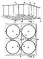
- FIG. 1 illustrates a bottom perspective view of a floating platform in accordance with an embodiment of the present invention.
- Floating platform 10 may include a plurality of variable buoyancy members 12 grouped in an array.
- the variable buoyancy members 12 may be joined to a top cap/plate.
- Top caps when assembled into an array, may combine to form the platform top 14, which may provide the working base for desired floating platform operations.
- Variable buoyancy members 12 may be tubular shaped columns that project downwardly into and below a surface of a body of water in which floating platform 10 is disposed.
- the buoyancy members may be made of steel reinforced concrete, or other suitable construction materials, including, but not limited to steel and/or other various metal alloys, synthetic materials, such as carbon fiber reinforced polymers, and the like.
- Variable buoyancy members 12 may have an opposite end 20 that is open and able to allow water to enter the hollow portion of the variable buoyancy members 12. Air in the variable buoyancy members 12 may displace water inside the variable buoyancy members 12 (internal water) to a depth greater than the external water level, and may controllably provide buoyancy via the air volume's pressure to resiliently support the platform 10.
- buoyancy members 12 may be comprised of any suitable building materials, such as reinforced concrete and/or steel, and may be of any simple or complex geometry, including, but not limited to a variety of polygonal cross sections.
- Buoyancy members 12 may be at least partially joined together by a bottom plate 16, such that some or all of the open ends 20 of the variable buoyancy members12, remain open to the water such that water can enter the buoyancy members 12.
- bottom plate 16 may have strength qualities substantially equal to that of the top plate 14, which may help resist the bending and torsion moments experienced by platform 10 in certain sea states and provide a stabilizing effect for the platform.
- Interstitial volumes 24 may be made controllably watertight and/or air-tight. When water tight, interstitial volumes 24 may provide sufficient reserve buoyancy for the floating platform 10 to keep the top platforms substantially above the water line in the event that some or all of the variable buoyancy members fail. It can be appreciated that bottom plate 16 may be configured such that the number of interstitial volumes 24, and thus the reserve buoyancy, may be selectively controlled.
- the interstitial volumes and variable buoyancy members may also aid in resisting forces applied or enhanced by extreme and/or unbalanced deck loads.
- air may be directed to selected variable buoyancy members and/or interstitial volumes in a certain area where downward force on a deck is greater than normal. Examples of such situations may be where large machinery is stored, or to counteract the effect of drill strings, anchor lines, etc.
- Such variable loading of selected interstitial volumes and/or variable buoyancy members with air may increase the loading capacity in certain areas of the platform, in that the amount of downward force that may be applied in the desired area may be increased without increasing the thickness of the platform top plate.
- the air pressure in the variable buoyancy members may also be increased to raise the platform height relative to the water.
- This may be useful for certain ship-to-platform operations, for maintaining tension on a oil production riser, to avoid wave slapping in heavy weather and to facilitate towing.
- the addition of compressed air in desired locations may be introduced by a high volume low pressure compressor, such as a Roots Blower.
- Controllably charging the interstitial volumes 24 with compressed air such that the air pressure in the interstitial volumes 24 is maintained at a pressure greater than or equal to that of the pressure created by the water submergence within any of the variable buoyancy members 12, may also significantly increase the material strength of the buoyancy members 12. Particularly where buoyancy members 12 are constructed of materials such as reinforced concrete, keeping a positive pressure on the outer walls may counteract or alleviate tangential tensile wall stresses created by the increase of air pressure within the buoyancy members 12.
- the interstitial volumes 24 may be enlarged as needed by increasing the width of the vertical partitions 18 and correspondingly increasing the spacing between adjacent variable buoyancy members 12. Increasing the interstitial volume 24 may increase the proportion of fixed buoyancy to variable buoyancy, which in turn provides more reserve buoyancy if needed in the event of a failure.
- the interstitial volumes may be interconnected with the adjacent variable buoyancy members. Allowing adjacent buoyancy members to be in air communication with an interstitial volume may result in a substantial increase of the volume-related pneumatic compliance of the buoyancy members against wave generated heave and other potential forces created by wave excitations and/or external sources.
- Embodiments in accordance with the present invention may enable the construction of platforms so large as to result in relatively calm waters on the leeward side of the platform.
- This leeward calming may also allow other floating vessels to dock adjacent to the floating platform, such that the relative motion between the docked vessel and the floating platform is minimized. This increases safety and facilitates the loading, unloading, fueling, and other vessel-to-platform type operations.
- FIG. 2 illustrates an enlarged sectional horizontal plan view of a floating platform in accordance with an embodiment of the present invention.
- Four vertical variable buoyancy members 12 are shown.
- Vertical partitions 18 may be disposed between and interconnect variable buoyancy members 12, to create interstitial volume 24.
- Interstitial volume 24 may be increased or decreased depending on platform configuration and/or buoyancy needs by increasing or decreasing the width 29 of vertical partitions 18.
- the floating platform may be reinforced with beams 26 and 28, which may extend laterally and longitudinally across a lower portion of the platform. Beams 26 and 28 may intersect vertical partitions 18 at or near the bottom of the buoyancy members 12. Beams 26 and 28 may be integral with the bottom plate 16, in order to provide additional strength to the bottom portion of the floating platform. It can be appreciated that beams 26 and 28 may intersect (as shown) or may be of different heights and widths such that they overlap at their intersection.
- the air within interstitial volumes 24 may be maintained at a pressure equal to or greater than the pressure inside variable buoyancy members 12. Maintaining such a positive pressure within surrounding interstitial volumes 24 may result in a generally circumferential compressive stress/force on walls 34 of that buoyancy member 12. This compressive stress may help the walls of the variable buoyancy members resist tensile stress cracking or problems resulting from forces imposed as a result of elevated pressure within the variable buoyancy members 12.
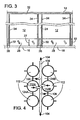
- FIG. 3 illustrates an enlarged cross sectional view of the floating platform of FIG. 2 in accordance with an embodiment of the present invention.
- One or more tendons 32 may be positioned in beams 26 and 28, as well as the top surface plate14.
- Tendons 32 may include, but are not limited to, members that may apply post-tension to structures to insure that the material, such as reinforced concrete material, remains in a state of compressive stress in the presence of the largest expected bending moment load in the platform.
- the height 27 of the beams 26 and 28 may vary depending on the platform configuration and the amount and types of stresses that may be incurred by the floating platform. For example, if a platform is longer in the direction for which beams 26 are running, beams 26 may be larger than beams 28 in order to withstand the added stress due to the longer span.
- FIG. 4 illustrates an enlarged plan view of a portion of a floating platform in accordance with an embodiment of the present invention.
- Several variable buoyancy members 112 may be configured in an array.
- Variable buoyancy members 112A and 112B may be interconnected by an airduct 108 and further interconnected to interstitial volumes 124A and 124B. Air, for example, may be controllably allowed to communicate freely through airduct 108 with the interstitial volumes 124.
- Such interconnection of the interstitial volumes 124A and 1248 with the buoyancy members 112A and 112B may result in a substantial increase of the volume-related pneumatic compliance of the buoyancy members 112 against wave generated heave forces, as well as other potential forces that may be encountered by the floating platform.
- buoyancy members 112A and 112B may flow from the buoyancy members 112A and 112B into interstitial volumes 124A and 124B, as shown by arrows 106.
- the direction and magnitude of the air flow between buoyancy members 112A and 112B may vary depending on the raising and lowering of the water levels in the buoyancy members, which in turn may increase and decrease the air pressure respectively.
- Using interstitial volumes 124A and 124B to increase in variable buoyancy volume may not only better stabilize the floating platform to the effects of wave excitation.
- air flow may be directed to other parts of the floating platform through airduct 108, as shown by arrows 104.
- the arrows generally indicate the direction of short-term air flow during a rising water level in the cylinders. This may enable the air to be routed to various buoyancy members and interstitial volumes that are interconnected, but remotely located. Such movement may thus enhance compliance by means of air mobility and reduces platform motions and structural loading in the event of significant wave activity.
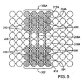
- FIG. 5 Illustrates a plan view of a floating platform in accordance with an embodiment of the present invention.
- a selected array of buoyancy members may be interconnected to a like array of buoyancy members positioned at different locations of the floating platform, which may aid in wave decoupling through the mobility of buoyancy air to different parts of the floating platform.
- air may be controllably ducted through airducts 208, 208A and 208B between a first array 202 to a second array 202A.
- second array 202A may be symmetric in size and number of buoyancy members and interstitial volumes to that of first array 202.
- second array 202A may be symmetrically situated across the width and/or across the length of the floating platform with respect to first array 202. It can be appreciated, however, that the number and position of arrays may be selected as needed to accommodate particular applications.
- Air mobility may be enhanced when the distance between arrays 202 and 202A is adequate to encompass a significant gradient in wave elevation and length. Distancing first array 202 from second array 202A may serve to enhance the compliance-related transport of air while preserving the level attitude of the platform in the event of asymmetric damage, for example, with consequent loss of buoyancy air.
- a network of valves 250 may be positioned in ducts 208, 208A and 208B that may be selectively actuatable to change the array configurations, and may enable, disable, enhance or reduce the effects of air mobility and control.
- High volume low pressure compressors may also be coupled to the network of valves and ducting to controllably introduce additional compressed air in various arrays, buoyancy members, and/or interstitial volumes as needed to provide necessary support for the floating platform generally or to localized areas.
- floating platforms in accordance with embodiments of the present invention may be well suited for constructing very large area floating platforms.
- Several platform segments or modules may be joined together and structurally supported by the top and bottom plate structures. These larger platforms may be sufficiently stable to allow such activities as landing and takeoff of aircraft, docking of ships for loading and unloading cargo and/or personnel.
Landscapes
- Engineering & Computer Science (AREA)
- Architecture (AREA)
- Civil Engineering (AREA)
- Structural Engineering (AREA)
- Chemical & Material Sciences (AREA)
- Combustion & Propulsion (AREA)
- Mechanical Engineering (AREA)
- Ocean & Marine Engineering (AREA)
- Revetment (AREA)
- Other Liquid Machine Or Engine Such As Wave Power Use (AREA)
- Bridges Or Land Bridges (AREA)
Claims (17)
- Plate-forme flottante (10), comportant :un plateau supérieur (14) ;une pluralité d'éléments de flottabilité variable (12 ; 112, 112A, 112B ; 212, 212A) configurés en un ensemble, chaque élément de flottabilité variable ayant une extrémité inférieure ouverte (20), et une extrémité supérieure fermée accouplée au plateau supérieur ;une pluralité de parois de séparation verticales (18), chacune reliant mutuellement dans le sens latéral et dans le sens longitudinal deux ou plusieurs parmi la pluralité d'éléments de flottabilité variable ;un plateau inférieur (16) configuré pour laisser au moins une extrémité inférieure ouverte d'au moins un élément de flottabilité exposée à un volume d'eau ;au moins un volume interstitiel (24 ; 124A, 124 ; 224, 224A) défini par les parois de séparation verticales reliant mutuellement trois éléments de flottabilité ou plus, et au moins un volume interstitiel étant scellé pour empêcher tout afflux du volume d'eau dans le volume interstitiel ; etcaractérisée en ce qu'un ensemble comportant ledit au moins un volume interstitiel et lesdits éléments de flottabilité est relié mutuellement de manière contrôlable avec au moins un autre ensemble comportant au moins un volume interstitiel et des éléments de flottabilité de telle sorte qu'un écoulement d'air entre ledit ensemble et ledit au moins un autre ensemble est contrôlable.
- Plate-forme flottante (10) selon la revendication 1, comportant par ailleurs un réseau de poutres (26, 28) disposées au niveau des éléments de flottabilité variable (12 ; 112, 112A, 112B ; 212, 212A) sensiblement au niveau ou à proximité de la partie inférieure des éléments de flottabilité variable.
- Plate-forme flottante (10) selon la revendication 2, dans laquelle le plateau inférieur (16) et le réseau de poutres (26, 28) ont une résistance et une rigidité qui sont sensiblement identiques à une résistance et une rigidité du plateau supérieur (14) de telle sorte que la plate-forme flottante a une structure équilibrée en superficie en mesure de résister à des moments de flexion induits par les vagues océaniques et induites par la charge de la plate-forme.
- Plate-forme flottante (10) selon la revendication 1, la revendication 2 ou la revendication 3, dans laquelle un ou plusieurs parmi les volumes interstitiels (24 ; 124A, 124B ; 224, 224A) sont un volume de refoulement non variable fixe qui procure suffisamment de flottabilité pour faire flotter la plate-forme en cas de perte totale de flottabilité variable dans les éléments de flottabilité (12 ; 112, 112A, 112B ; 212, 212A).
- Plate-forme flottante (10) selon la revendication 1, la revendication 2 ou la revendication 3, dans laquelle les volumes interstitiels (24 ; 124A, 124B ; 224, 224A) ont une première pression d'air et les éléments de flottabilité (12 ; 112, 112A, 112B ; 212, 212A) ont une seconde pression d'air.
- Plate-forme flottante (10) selon la revendication 5, dans laquelle la première pression d'air est contrôlée pour rester sensiblement égale ou supérieure à la seconde pression d'air.
- Plate-forme flottante (10) selon la revendication 1, la revendication 2 ou la revendication 3, dans laquelle les volumes interstitiels (24 ; 124A, 124B ; 224, 224A) sont augmentés en augmentant la largeur (29) des parois de séparation verticales (18) pour augmenter la séparation des éléments de flottabilité variable adjacents (12 ; 112, 112A, 112B ; 212, 212A).
- Plate-forme flottante (10) selon la revendication 1, la revendication 2 ou la revendication 3, dans laquelle au moins un volume interstitiel (24 ; 124A, 124B ; 224, 224A) est relié à au moins un élément de flottabilité variable adjacent (12 ; 112, 112A, 112B ; 212, 212A) pour permettre une communication d'air entre ceux-ci et augmenter un volume disponible dudit au moins un élément de flottabilité variable.
- Plate-forme flottante (10) selon la revendication 1, la revendication 2 ou la revendication 3, dans laquelle une alimentation en milieu gazeux (108) est accouplée aux volumes interstitiels (24 ; 124A, 124B ; 224, 224A) et aux éléments de flottabilité variable (12 ; 112, 112A, 112B ; 212, 212A) et est configurée pour alimenter de manière contrôlable le milieu gazeux aux volumes interstitiels et/ou aux éléments de flottabilité variable, soit séparément soit ensemble.
- Plate-forme flottante (10) selon la revendication 9, dans laquelle la pression du milieu gazeux est augmentée dans une zone localisée pour procurer une plus grande capacité de charge pour le plateau supérieur (14) dans la zone localisée.
- Plate-forme flottante (10) selon la revendication 9 ou la revendication 10, dans laquelle la pression est augmentée dans les éléments de flottabilité variable (12 ; 112, 112A, 112B ; 212, 212A) pour relever la plate-forme dans le volume d'eau.
- Plate-forme flottante (10) selon l'une quelconque des revendications précédentes, comportant par ailleurs :un premier ensemble (202) d'éléments de flottabilité variable (212) et de volumes interstitiels (224) ;un second ensemble (202A) d'éléments de flottabilité (212A) et de volumes interstitiels (224A) ;un ou plusieurs conduits d'air (208, 208A, 208B) reliant mutuellement un ou plusieurs éléments de flottabilité et/ou un ou plusieurs volumes interstitiels du premier ensemble avec un ou plusieurs éléments de flottabilité et/ou un ou plusieurs volumes interstitiels du second ensemble ;un réseau de vannes (250) placées à l'intérieur desdits un ou plusieurs conduits d'air pour, de manière contrôlable, permettre un échange d'air entre le premier ensemble et le second ensemble.
- Plate-forme flottante (10) selon la revendication 12, dans laquelle le premier ensemble (202) et le second ensemble (202A) sont symétriques en termes de taille, de forme et de position à l'intérieur de la plate-forme flottante.
- Plate-forme flottante (10) selon la revendication 12 ou la revendication 13, dans laquelle l'air peut être déplacé en provenance du premier ensemble (202) vers le second ensemble (202A) à des fins de compensation d'une perte provisoire de flottabilité variable dans le second ensemble.
- Plate-forme flottante (10) selon l'une quelconque des revendications précédentes, dans laquelle la plate-forme a un côté au vent et un côté sous le vent, et dans laquelle la pluralité d'éléments de flottabilité variable (12 ; 112, 112A, 112B ; 212, 212A) sont adaptés à des fins d'atténuation d'une activité de vague lors de son passage sous la plate-forme flottante depuis de côté au vent vers le côté sous le vent.
- Plate-forme flottante (10) selon la revendication 15, dans laquelle le côté sous le vent est adapté à des fins d'accostage de navires.
- Plate-forme flottante (10) selon la revendication 9, la revendication 10 ou la revendication 11, dans laquelle le milieu gazeux est de l'air fourni par un compresseur basse pression de haut volume.
Applications Claiming Priority (1)
| Application Number | Priority Date | Filing Date | Title |
|---|---|---|---|
| PCT/US2004/018687 WO2006001796A1 (fr) | 2004-06-09 | 2004-06-09 | Procede et appareil de plate-forme flottante |
Publications (3)
| Publication Number | Publication Date |
|---|---|
| EP1753653A1 EP1753653A1 (fr) | 2007-02-21 |
| EP1753653A4 EP1753653A4 (fr) | 2010-03-31 |
| EP1753653B1 true EP1753653B1 (fr) | 2013-11-06 |
Family
ID=35782094
Family Applications (1)
| Application Number | Title | Priority Date | Filing Date |
|---|---|---|---|
| EP04755063.7A Expired - Lifetime EP1753653B1 (fr) | 2004-06-09 | 2004-06-09 | Plate-forme flottante |
Country Status (5)
| Country | Link |
|---|---|
| US (1) | US7823525B2 (fr) |
| EP (1) | EP1753653B1 (fr) |
| KR (1) | KR101140488B1 (fr) |
| CN (1) | CN1964886A (fr) |
| WO (1) | WO2006001796A1 (fr) |
Families Citing this family (26)
| Publication number | Priority date | Publication date | Assignee | Title |
|---|---|---|---|---|
| IL173254A0 (en) * | 2006-01-19 | 2007-03-08 | Israel Aerospace Ind Ltd | Floating platform |
| US20090126937A1 (en) * | 2007-11-19 | 2009-05-21 | Millheim Keith K | Self-Standing Riser System Having Multiple Buoyancy Chambers |
| GB2463476B (en) * | 2008-09-11 | 2012-06-27 | Kavoss Hashemzadeh | Floating platform |
| US20120051845A1 (en) * | 2009-01-15 | 2012-03-01 | Ocean Brick System (O.B.S.) Ltd. | Deep water port |
| US9683346B2 (en) | 2009-01-15 | 2017-06-20 | Ocean Brick Systems (O.B.S.) Ltd. | Perforated structure mountable onto a seabed |
| WO2010108163A2 (fr) * | 2009-03-20 | 2010-09-23 | Float Incorporated | Système offshore flottant d'énergie océanique |
| AT511850B1 (de) * | 2011-07-13 | 2013-03-15 | Univ Wien Tech | Schwimmplattform |
| CN102381451A (zh) * | 2011-08-26 | 2012-03-21 | 侯唯敏 | 组合式浮箱及其搭建方法 |
| KR101427603B1 (ko) * | 2012-05-16 | 2014-08-07 | 한국해양과학기술원 | 절단 스파형 부유식 해상풍력 플랫폼 |
| AT513591A2 (de) * | 2012-07-10 | 2014-05-15 | Shang Kejian | Kraftwerksanlage |
| CN102765467B (zh) * | 2012-08-10 | 2014-11-26 | 江苏中蕴风电科技有限公司 | 一种可移动海洋漂浮式主体模块结构 |
| US9168987B1 (en) | 2014-01-16 | 2015-10-27 | Sergey Sharapov | Geographically stable floating platform structure |
| TW201615488A (zh) * | 2014-10-27 | 2016-05-01 | Guang-Zheng Chen | 浮島裝置 |
| TW201632409A (zh) * | 2015-03-04 | 2016-09-16 | Guang-Zheng Chen | 浮島裝置 |
| ITUA20164177A1 (it) * | 2016-06-08 | 2017-12-08 | Pezone Luigi Antonio | Sistema di galleggiamento con tubi in polietilene estrusi, nervati, rinforzati e riempiti di polistirolo. |
| ES2660913B1 (es) * | 2016-08-26 | 2019-01-22 | Clecoser S L | Plataforma flotante sumergible de trabajo o almacenamiento |
| CN106761407A (zh) * | 2016-11-29 | 2017-05-31 | 中国地质大学(武汉) | 一种水上勘探装置 |
| US10538295B2 (en) * | 2018-04-24 | 2020-01-21 | Spherical Block LLC | Floating base |
| US11156201B2 (en) * | 2018-05-17 | 2021-10-26 | Lone Gull Holdings, Ltd. | Inertial pneumatic wave energy device |
| CN110510075A (zh) * | 2018-11-21 | 2019-11-29 | 广东省渔小清科技有限公司 | 水上漂浮装置及其漂浮方法 |
| IL268914B (en) * | 2019-08-26 | 2022-08-01 | Israel Ports Dev & Assets Company Ltd | A marine construction and a method for constructing the same |
| KR102186902B1 (ko) * | 2019-10-28 | 2020-12-04 | 강흥묵 | 침수형 부상 조립체 |
| NL2027165B1 (en) * | 2020-12-18 | 2022-07-15 | Mct Mesh Construction Tech Holding B V | Floating structure and container and bridge part for use in a floating structure, and method of stabilizing a floating structure |
| KR102330938B1 (ko) * | 2021-04-05 | 2021-12-01 | 주식회사 브리콘 | 중공 콘크리트 부유 구조물 |
| JP7347764B2 (ja) | 2021-06-25 | 2023-09-20 | 株式会社長大 | 複合浮体基盤および当該複合浮体基盤を備える浮体式洋上風力発電設備 |
| WO2024013526A1 (fr) * | 2022-07-14 | 2024-01-18 | Frano Zanki | Objet flottant insubmersible ne basculant pas sur les vagues de la mer |
Family Cites Families (10)
| Publication number | Priority date | Publication date | Assignee | Title |
|---|---|---|---|---|
| US3490407A (en) | 1968-10-23 | 1970-01-20 | Harry E Dempster | Concrete floating structure |
| US3833035A (en) | 1971-11-22 | 1974-09-03 | A Yee | Floating or submerged marine vessel for storage, support or transport |
| US4261277A (en) * | 1979-04-09 | 1981-04-14 | Seatek Corporation | System for stabilizing a floating vessel |
| US4864958A (en) | 1987-09-25 | 1989-09-12 | Belinsky Sidney I | Swap type floating platforms |
| US5375550A (en) * | 1992-04-13 | 1994-12-27 | Innis; Donald A. | Stabilized floating platform assembly |
| US5235929A (en) * | 1992-07-29 | 1993-08-17 | Leisure Docks Inc. | Docking system |
| US6401625B1 (en) | 1996-09-05 | 2002-06-11 | J. Kirston Henderson | Machine for transport of passengers and cargo |
| US6213045B1 (en) * | 1998-08-27 | 2001-04-10 | Steve J. Gaber | Flotation system and method for off-shore platform and the like |
| US20030140838A1 (en) | 2002-01-29 | 2003-07-31 | Horton Edward E. | Cellular SPAR apparatus and method |
| US6791206B1 (en) | 2002-06-14 | 2004-09-14 | David D. Woodbridge | Method for making a stabilized energy conversion operating platform |
-
2004
- 2004-06-09 KR KR1020077000501A patent/KR101140488B1/ko not_active Expired - Fee Related
- 2004-06-09 WO PCT/US2004/018687 patent/WO2006001796A1/fr not_active Ceased
- 2004-06-09 US US11/569,869 patent/US7823525B2/en active Active
- 2004-06-09 EP EP04755063.7A patent/EP1753653B1/fr not_active Expired - Lifetime
- 2004-06-09 CN CNA2004800432601A patent/CN1964886A/zh active Pending
Also Published As
| Publication number | Publication date |
|---|---|
| CN1964886A (zh) | 2007-05-16 |
| US20090173269A1 (en) | 2009-07-09 |
| EP1753653A1 (fr) | 2007-02-21 |
| US7823525B2 (en) | 2010-11-02 |
| EP1753653A4 (fr) | 2010-03-31 |
| WO2006001796A1 (fr) | 2006-01-05 |
| KR101140488B1 (ko) | 2012-04-30 |
| KR20070045185A (ko) | 2007-05-02 |
Similar Documents
| Publication | Publication Date | Title |
|---|---|---|
| EP1753653B1 (fr) | Plate-forme flottante | |
| US6652192B1 (en) | Heave suppressed offshore drilling and production platform and method of installation | |
| US6899492B1 (en) | Jacket frame floating structures with buoyancy capsules | |
| US11052971B2 (en) | Floating offshore platform | |
| US8387550B2 (en) | Offshore floating platform with motion damper columns | |
| US6761124B1 (en) | Column-stabilized floating structures with truss pontoons | |
| EP2007619B1 (fr) | Plate-forme de type fpso mono-colonne | |
| US3986471A (en) | Semi-submersible vessels | |
| US6431107B1 (en) | Tendon-based floating structure | |
| US7934462B2 (en) | Offshore floating structure with motion dampers | |
| US6701861B2 (en) | Semi-submersible floating production facility | |
| GB2459904A (en) | A pontoonless tension leg platform | |
| US8251002B2 (en) | Pontoon-type floating structure | |
| US8752496B2 (en) | Semi-submersible vessel, method for operating a semi-submersible vessel and method for manufacturing a semi-submersible vessel | |
| WO2015136086A1 (fr) | Structure de quai, agencement de quai et méthode d'installation d'une telle structure | |
| RU2433937C2 (ru) | Судно (варианты), устройство для уменьшения качки, погружное тело, устройство стабилизации и способ уменьшения качки | |
| US9415843B1 (en) | Floating driller | |
| GB2570453A (en) | Floating deck assembly | |
| WO2021255509A1 (fr) | Plateforme flottante à colonnes inclinées | |
| Clauss | The conquest of the inner space-challenges and innovations in offshore technology | |
| GB2137578A (en) | Floating vessels | |
| GB2583597A (en) | Floating deck assembly | |
| Clauss | The Conquest of the Inner Space: Design and Analysis of Offshore Structures |
Legal Events
| Date | Code | Title | Description |
|---|---|---|---|
| PUAI | Public reference made under article 153(3) epc to a published international application that has entered the european phase |
Free format text: ORIGINAL CODE: 0009012 |
|
| 17P | Request for examination filed |
Effective date: 20061127 |
|
| AK | Designated contracting states |
Kind code of ref document: A1 Designated state(s): AT BE BG CH CY CZ DE DK EE ES FI FR GB GR HU IE IT LI LU MC NL PL PT RO SE SI SK TR |
|
| DAX | Request for extension of the european patent (deleted) | ||
| A4 | Supplementary search report drawn up and despatched |
Effective date: 20100225 |
|
| 17Q | First examination report despatched |
Effective date: 20100512 |
|
| RIC1 | Information provided on ipc code assigned before grant |
Ipc: B63B 35/44 20060101AFI20130418BHEP Ipc: B63B 39/10 20060101ALN20130418BHEP |
|
| GRAP | Despatch of communication of intention to grant a patent |
Free format text: ORIGINAL CODE: EPIDOSNIGR1 |
|
| RIC1 | Information provided on ipc code assigned before grant |
Ipc: B63B 39/10 20060101ALN20130506BHEP Ipc: B63B 35/44 20060101AFI20130506BHEP |
|
| INTG | Intention to grant announced |
Effective date: 20130528 |
|
| GRAS | Grant fee paid |
Free format text: ORIGINAL CODE: EPIDOSNIGR3 |
|
| GRAA | (expected) grant |
Free format text: ORIGINAL CODE: 0009210 |
|
| AK | Designated contracting states |
Kind code of ref document: B1 Designated state(s): AT BE BG CH CY CZ DE DK EE ES FI FR GB GR HU IE IT LI LU MC NL PL PT RO SE SI SK TR |
|
| REG | Reference to a national code |
Ref country code: GB Ref legal event code: FG4D |
|
| REG | Reference to a national code |
Ref country code: CH Ref legal event code: EP |
|
| REG | Reference to a national code |
Ref country code: AT Ref legal event code: REF Ref document number: 639264 Country of ref document: AT Kind code of ref document: T Effective date: 20131215 |
|
| REG | Reference to a national code |
Ref country code: IE Ref legal event code: FG4D |
|
| REG | Reference to a national code |
Ref country code: DE Ref legal event code: R096 Ref document number: 602004043738 Country of ref document: DE Effective date: 20140102 |
|
| REG | Reference to a national code |
Ref country code: NL Ref legal event code: VDEP Effective date: 20131106 |
|
| REG | Reference to a national code |
Ref country code: AT Ref legal event code: MK05 Ref document number: 639264 Country of ref document: AT Kind code of ref document: T Effective date: 20131106 |
|
| PG25 | Lapsed in a contracting state [announced via postgrant information from national office to epo] |
Ref country code: NL Free format text: LAPSE BECAUSE OF FAILURE TO SUBMIT A TRANSLATION OF THE DESCRIPTION OR TO PAY THE FEE WITHIN THE PRESCRIBED TIME-LIMIT Effective date: 20131106 Ref country code: FI Free format text: LAPSE BECAUSE OF FAILURE TO SUBMIT A TRANSLATION OF THE DESCRIPTION OR TO PAY THE FEE WITHIN THE PRESCRIBED TIME-LIMIT Effective date: 20131106 Ref country code: SE Free format text: LAPSE BECAUSE OF FAILURE TO SUBMIT A TRANSLATION OF THE DESCRIPTION OR TO PAY THE FEE WITHIN THE PRESCRIBED TIME-LIMIT Effective date: 20131106 |
|
| PG25 | Lapsed in a contracting state [announced via postgrant information from national office to epo] |
Ref country code: AT Free format text: LAPSE BECAUSE OF FAILURE TO SUBMIT A TRANSLATION OF THE DESCRIPTION OR TO PAY THE FEE WITHIN THE PRESCRIBED TIME-LIMIT Effective date: 20131106 Ref country code: BE Free format text: LAPSE BECAUSE OF FAILURE TO SUBMIT A TRANSLATION OF THE DESCRIPTION OR TO PAY THE FEE WITHIN THE PRESCRIBED TIME-LIMIT Effective date: 20131106 Ref country code: ES Free format text: LAPSE BECAUSE OF FAILURE TO SUBMIT A TRANSLATION OF THE DESCRIPTION OR TO PAY THE FEE WITHIN THE PRESCRIBED TIME-LIMIT Effective date: 20131106 |
|
| PG25 | Lapsed in a contracting state [announced via postgrant information from national office to epo] |
Ref country code: PT Free format text: LAPSE BECAUSE OF FAILURE TO SUBMIT A TRANSLATION OF THE DESCRIPTION OR TO PAY THE FEE WITHIN THE PRESCRIBED TIME-LIMIT Effective date: 20140306 |
|
| PG25 | Lapsed in a contracting state [announced via postgrant information from national office to epo] |
Ref country code: EE Free format text: LAPSE BECAUSE OF FAILURE TO SUBMIT A TRANSLATION OF THE DESCRIPTION OR TO PAY THE FEE WITHIN THE PRESCRIBED TIME-LIMIT Effective date: 20131106 |
|
| REG | Reference to a national code |
Ref country code: DE Ref legal event code: R097 Ref document number: 602004043738 Country of ref document: DE |
|
| PG25 | Lapsed in a contracting state [announced via postgrant information from national office to epo] |
Ref country code: SK Free format text: LAPSE BECAUSE OF FAILURE TO SUBMIT A TRANSLATION OF THE DESCRIPTION OR TO PAY THE FEE WITHIN THE PRESCRIBED TIME-LIMIT Effective date: 20131106 Ref country code: CZ Free format text: LAPSE BECAUSE OF FAILURE TO SUBMIT A TRANSLATION OF THE DESCRIPTION OR TO PAY THE FEE WITHIN THE PRESCRIBED TIME-LIMIT Effective date: 20131106 Ref country code: IT Free format text: LAPSE BECAUSE OF FAILURE TO SUBMIT A TRANSLATION OF THE DESCRIPTION OR TO PAY THE FEE WITHIN THE PRESCRIBED TIME-LIMIT Effective date: 20131106 Ref country code: RO Free format text: LAPSE BECAUSE OF FAILURE TO SUBMIT A TRANSLATION OF THE DESCRIPTION OR TO PAY THE FEE WITHIN THE PRESCRIBED TIME-LIMIT Effective date: 20131106 Ref country code: PL Free format text: LAPSE BECAUSE OF FAILURE TO SUBMIT A TRANSLATION OF THE DESCRIPTION OR TO PAY THE FEE WITHIN THE PRESCRIBED TIME-LIMIT Effective date: 20131106 |
|
| PLBE | No opposition filed within time limit |
Free format text: ORIGINAL CODE: 0009261 |
|
| STAA | Information on the status of an ep patent application or granted ep patent |
Free format text: STATUS: NO OPPOSITION FILED WITHIN TIME LIMIT |
|
| PG25 | Lapsed in a contracting state [announced via postgrant information from national office to epo] |
Ref country code: DK Free format text: LAPSE BECAUSE OF FAILURE TO SUBMIT A TRANSLATION OF THE DESCRIPTION OR TO PAY THE FEE WITHIN THE PRESCRIBED TIME-LIMIT Effective date: 20131106 |
|
| 26N | No opposition filed |
Effective date: 20140807 |
|
| REG | Reference to a national code |
Ref country code: DE Ref legal event code: R097 Ref document number: 602004043738 Country of ref document: DE Effective date: 20140807 |
|
| REG | Reference to a national code |
Ref country code: DE Ref legal event code: R119 Ref document number: 602004043738 Country of ref document: DE |
|
| PG25 | Lapsed in a contracting state [announced via postgrant information from national office to epo] |
Ref country code: LU Free format text: LAPSE BECAUSE OF FAILURE TO SUBMIT A TRANSLATION OF THE DESCRIPTION OR TO PAY THE FEE WITHIN THE PRESCRIBED TIME-LIMIT Effective date: 20140609 Ref country code: MC Free format text: LAPSE BECAUSE OF FAILURE TO SUBMIT A TRANSLATION OF THE DESCRIPTION OR TO PAY THE FEE WITHIN THE PRESCRIBED TIME-LIMIT Effective date: 20131106 |
|
| REG | Reference to a national code |
Ref country code: CH Ref legal event code: PL |
|
| PG25 | Lapsed in a contracting state [announced via postgrant information from national office to epo] |
Ref country code: SI Free format text: LAPSE BECAUSE OF FAILURE TO SUBMIT A TRANSLATION OF THE DESCRIPTION OR TO PAY THE FEE WITHIN THE PRESCRIBED TIME-LIMIT Effective date: 20131106 |
|
| REG | Reference to a national code |
Ref country code: FR Ref legal event code: ST Effective date: 20150227 |
|
| REG | Reference to a national code |
Ref country code: DE Ref legal event code: R119 Ref document number: 602004043738 Country of ref document: DE Effective date: 20150101 |
|
| PG25 | Lapsed in a contracting state [announced via postgrant information from national office to epo] |
Ref country code: CH Free format text: LAPSE BECAUSE OF NON-PAYMENT OF DUE FEES Effective date: 20140630 Ref country code: LI Free format text: LAPSE BECAUSE OF NON-PAYMENT OF DUE FEES Effective date: 20140630 Ref country code: DE Free format text: LAPSE BECAUSE OF NON-PAYMENT OF DUE FEES Effective date: 20150101 |
|
| PG25 | Lapsed in a contracting state [announced via postgrant information from national office to epo] |
Ref country code: FR Free format text: LAPSE BECAUSE OF NON-PAYMENT OF DUE FEES Effective date: 20140630 |
|
| PG25 | Lapsed in a contracting state [announced via postgrant information from national office to epo] |
Ref country code: BG Free format text: LAPSE BECAUSE OF FAILURE TO SUBMIT A TRANSLATION OF THE DESCRIPTION OR TO PAY THE FEE WITHIN THE PRESCRIBED TIME-LIMIT Effective date: 20131106 |
|
| PG25 | Lapsed in a contracting state [announced via postgrant information from national office to epo] |
Ref country code: CY Free format text: LAPSE BECAUSE OF FAILURE TO SUBMIT A TRANSLATION OF THE DESCRIPTION OR TO PAY THE FEE WITHIN THE PRESCRIBED TIME-LIMIT Effective date: 20131106 Ref country code: GR Free format text: LAPSE BECAUSE OF FAILURE TO SUBMIT A TRANSLATION OF THE DESCRIPTION OR TO PAY THE FEE WITHIN THE PRESCRIBED TIME-LIMIT Effective date: 20140207 |
|
| PG25 | Lapsed in a contracting state [announced via postgrant information from national office to epo] |
Ref country code: HU Free format text: LAPSE BECAUSE OF FAILURE TO SUBMIT A TRANSLATION OF THE DESCRIPTION OR TO PAY THE FEE WITHIN THE PRESCRIBED TIME-LIMIT; INVALID AB INITIO Effective date: 20040609 Ref country code: TR Free format text: LAPSE BECAUSE OF FAILURE TO SUBMIT A TRANSLATION OF THE DESCRIPTION OR TO PAY THE FEE WITHIN THE PRESCRIBED TIME-LIMIT Effective date: 20131106 |
|
| P01 | Opt-out of the competence of the unified patent court (upc) registered |
Effective date: 20230517 |
|
| PGFP | Annual fee paid to national office [announced via postgrant information from national office to epo] |
Ref country code: IE Payment date: 20230710 Year of fee payment: 20 Ref country code: GB Payment date: 20230706 Year of fee payment: 20 |
|
| PG25 | Lapsed in a contracting state [announced via postgrant information from national office to epo] |
Ref country code: GB Free format text: LAPSE BECAUSE OF EXPIRATION OF PROTECTION Effective date: 20240608 |
|
| PG25 | Lapsed in a contracting state [announced via postgrant information from national office to epo] |
Ref country code: GB Free format text: LAPSE BECAUSE OF EXPIRATION OF PROTECTION Effective date: 20240608 |
|
| PG25 | Lapsed in a contracting state [announced via postgrant information from national office to epo] |
Ref country code: IE Free format text: LAPSE BECAUSE OF EXPIRATION OF PROTECTION Effective date: 20240609 |
|
| PG25 | Lapsed in a contracting state [announced via postgrant information from national office to epo] |
Ref country code: IE Free format text: LAPSE BECAUSE OF EXPIRATION OF PROTECTION Effective date: 20240609 |