EP1753518B1 - Filtre pour la filtration des liquides - Google Patents
Filtre pour la filtration des liquides Download PDFInfo
- Publication number
- EP1753518B1 EP1753518B1 EP05733040A EP05733040A EP1753518B1 EP 1753518 B1 EP1753518 B1 EP 1753518B1 EP 05733040 A EP05733040 A EP 05733040A EP 05733040 A EP05733040 A EP 05733040A EP 1753518 B1 EP1753518 B1 EP 1753518B1
- Authority
- EP
- European Patent Office
- Prior art keywords
- seal
- end cap
- filter
- diameter
- column
- Prior art date
- Legal status (The legal status is an assumption and is not a legal conclusion. Google has not performed a legal analysis and makes no representation as to the accuracy of the status listed.)
- Active
Links
- 239000007788 liquid Substances 0.000 title claims description 104
- 239000012530 fluid Substances 0.000 claims description 13
- 238000010276 construction Methods 0.000 claims description 8
- 238000004891 communication Methods 0.000 claims description 6
- 238000013461 design Methods 0.000 description 23
- 238000000034 method Methods 0.000 description 20
- 238000004364 calculation method Methods 0.000 description 19
- 230000000712 assembly Effects 0.000 description 17
- 238000000429 assembly Methods 0.000 description 17
- 238000011144 upstream manufacturing Methods 0.000 description 16
- 230000008901 benefit Effects 0.000 description 11
- 238000001914 filtration Methods 0.000 description 10
- 238000013459 approach Methods 0.000 description 9
- 238000007789 sealing Methods 0.000 description 9
- 239000000356 contaminant Substances 0.000 description 8
- 239000000463 material Substances 0.000 description 8
- 239000002184 metal Substances 0.000 description 7
- 229910052751 metal Inorganic materials 0.000 description 7
- 239000004033 plastic Substances 0.000 description 6
- 230000008859 change Effects 0.000 description 5
- 230000000694 effects Effects 0.000 description 5
- 238000009434 installation Methods 0.000 description 5
- 238000007689 inspection Methods 0.000 description 4
- 238000012360 testing method Methods 0.000 description 4
- 238000009472 formulation Methods 0.000 description 3
- 239000000446 fuel Substances 0.000 description 3
- 230000005484 gravity Effects 0.000 description 3
- 239000000203 mixture Substances 0.000 description 3
- 239000003921 oil Substances 0.000 description 3
- 230000009467 reduction Effects 0.000 description 3
- 230000004888 barrier function Effects 0.000 description 2
- 238000012512 characterization method Methods 0.000 description 2
- 230000003247 decreasing effect Effects 0.000 description 2
- 230000002829 reductive effect Effects 0.000 description 2
- 238000012546 transfer Methods 0.000 description 2
- NCGICGYLBXGBGN-UHFFFAOYSA-N 3-morpholin-4-yl-1-oxa-3-azonia-2-azanidacyclopent-3-en-5-imine;hydrochloride Chemical compound Cl.[N-]1OC(=N)C=[N+]1N1CCOCC1 NCGICGYLBXGBGN-UHFFFAOYSA-N 0.000 description 1
- TVEXGJYMHHTVKP-UHFFFAOYSA-N 6-oxabicyclo[3.2.1]oct-3-en-7-one Chemical compound C1C2C(=O)OC1C=CC2 TVEXGJYMHHTVKP-UHFFFAOYSA-N 0.000 description 1
- 229920001944 Plastisol Polymers 0.000 description 1
- 238000000418 atomic force spectrum Methods 0.000 description 1
- 238000005452 bending Methods 0.000 description 1
- 238000007906 compression Methods 0.000 description 1
- 230000006835 compression Effects 0.000 description 1
- 238000012790 confirmation Methods 0.000 description 1
- 239000000428 dust Substances 0.000 description 1
- 230000002401 inhibitory effect Effects 0.000 description 1
- 230000005764 inhibitory process Effects 0.000 description 1
- 230000001050 lubricating effect Effects 0.000 description 1
- 239000010687 lubricating oil Substances 0.000 description 1
- 238000012067 mathematical method Methods 0.000 description 1
- 238000013178 mathematical model Methods 0.000 description 1
- 238000005259 measurement Methods 0.000 description 1
- 239000002991 molded plastic Substances 0.000 description 1
- 230000002093 peripheral effect Effects 0.000 description 1
- 239000004999 plastisol Substances 0.000 description 1
- 229920000642 polymer Polymers 0.000 description 1
- 230000002441 reversible effect Effects 0.000 description 1
- 238000012552 review Methods 0.000 description 1
- 239000000565 sealant Substances 0.000 description 1
- 230000007704 transition Effects 0.000 description 1
- 239000002699 waste material Substances 0.000 description 1
Images


Classifications
-
- B—PERFORMING OPERATIONS; TRANSPORTING
- B01—PHYSICAL OR CHEMICAL PROCESSES OR APPARATUS IN GENERAL
- B01D—SEPARATION
- B01D29/00—Filters with filtering elements stationary during filtration, e.g. pressure or suction filters, not covered by groups B01D24/00 - B01D27/00; Filtering elements therefor
- B01D29/01—Filters with filtering elements stationary during filtration, e.g. pressure or suction filters, not covered by groups B01D24/00 - B01D27/00; Filtering elements therefor with flat filtering elements
- B01D29/016—Filters with filtering elements stationary during filtration, e.g. pressure or suction filters, not covered by groups B01D24/00 - B01D27/00; Filtering elements therefor with flat filtering elements with corrugated, folded or wound filtering elements
-
- B—PERFORMING OPERATIONS; TRANSPORTING
- B01—PHYSICAL OR CHEMICAL PROCESSES OR APPARATUS IN GENERAL
- B01D—SEPARATION
- B01D29/00—Filters with filtering elements stationary during filtration, e.g. pressure or suction filters, not covered by groups B01D24/00 - B01D27/00; Filtering elements therefor
- B01D29/11—Filters with filtering elements stationary during filtration, e.g. pressure or suction filters, not covered by groups B01D24/00 - B01D27/00; Filtering elements therefor with bag, cage, hose, tube, sleeve or like filtering elements
- B01D29/13—Supported filter elements
- B01D29/15—Supported filter elements arranged for inward flow filtration
- B01D29/21—Supported filter elements arranged for inward flow filtration with corrugated, folded or wound sheets
-
- B—PERFORMING OPERATIONS; TRANSPORTING
- B01—PHYSICAL OR CHEMICAL PROCESSES OR APPARATUS IN GENERAL
- B01D—SEPARATION
- B01D35/00—Filtering devices having features not specifically covered by groups B01D24/00 - B01D33/00, or for applications not specifically covered by groups B01D24/00 - B01D33/00; Auxiliary devices for filtration; Filter housing constructions
- B01D35/30—Filter housing constructions
-
- B—PERFORMING OPERATIONS; TRANSPORTING
- B01—PHYSICAL OR CHEMICAL PROCESSES OR APPARATUS IN GENERAL
- B01D—SEPARATION
- B01D29/00—Filters with filtering elements stationary during filtration, e.g. pressure or suction filters, not covered by groups B01D24/00 - B01D27/00; Filtering elements therefor
- B01D29/11—Filters with filtering elements stationary during filtration, e.g. pressure or suction filters, not covered by groups B01D24/00 - B01D27/00; Filtering elements therefor with bag, cage, hose, tube, sleeve or like filtering elements
- B01D29/13—Supported filter elements
- B01D29/23—Supported filter elements arranged for outward flow filtration
- B01D29/232—Supported filter elements arranged for outward flow filtration with corrugated, folded or wound sheets
-
- B—PERFORMING OPERATIONS; TRANSPORTING
- B01—PHYSICAL OR CHEMICAL PROCESSES OR APPARATUS IN GENERAL
- B01D—SEPARATION
- B01D29/00—Filters with filtering elements stationary during filtration, e.g. pressure or suction filters, not covered by groups B01D24/00 - B01D27/00; Filtering elements therefor
- B01D29/11—Filters with filtering elements stationary during filtration, e.g. pressure or suction filters, not covered by groups B01D24/00 - B01D27/00; Filtering elements therefor with bag, cage, hose, tube, sleeve or like filtering elements
- B01D29/31—Self-supporting filtering elements
-
- B—PERFORMING OPERATIONS; TRANSPORTING
- B01—PHYSICAL OR CHEMICAL PROCESSES OR APPARATUS IN GENERAL
- B01D—SEPARATION
- B01D35/00—Filtering devices having features not specifically covered by groups B01D24/00 - B01D33/00, or for applications not specifically covered by groups B01D24/00 - B01D33/00; Auxiliary devices for filtration; Filter housing constructions
- B01D35/14—Safety devices specially adapted for filtration; Devices for indicating clogging
- B01D35/147—Bypass or safety valves
-
- B—PERFORMING OPERATIONS; TRANSPORTING
- B01—PHYSICAL OR CHEMICAL PROCESSES OR APPARATUS IN GENERAL
- B01D—SEPARATION
- B01D35/00—Filtering devices having features not specifically covered by groups B01D24/00 - B01D33/00, or for applications not specifically covered by groups B01D24/00 - B01D33/00; Auxiliary devices for filtration; Filter housing constructions
- B01D35/14—Safety devices specially adapted for filtration; Devices for indicating clogging
- B01D35/153—Anti-leakage or anti-return valves
-
- B—PERFORMING OPERATIONS; TRANSPORTING
- B01—PHYSICAL OR CHEMICAL PROCESSES OR APPARATUS IN GENERAL
- B01D—SEPARATION
- B01D35/00—Filtering devices having features not specifically covered by groups B01D24/00 - B01D33/00, or for applications not specifically covered by groups B01D24/00 - B01D33/00; Auxiliary devices for filtration; Filter housing constructions
- B01D35/16—Cleaning-out devices, e.g. for removing the cake from the filter casing or for evacuating the last remnants of liquid
-
- B—PERFORMING OPERATIONS; TRANSPORTING
- B01—PHYSICAL OR CHEMICAL PROCESSES OR APPARATUS IN GENERAL
- B01D—SEPARATION
- B01D35/00—Filtering devices having features not specifically covered by groups B01D24/00 - B01D33/00, or for applications not specifically covered by groups B01D24/00 - B01D33/00; Auxiliary devices for filtration; Filter housing constructions
- B01D35/30—Filter housing constructions
- B01D35/306—Filter mounting adapter
-
- B—PERFORMING OPERATIONS; TRANSPORTING
- B01—PHYSICAL OR CHEMICAL PROCESSES OR APPARATUS IN GENERAL
- B01D—SEPARATION
- B01D63/00—Apparatus in general for separation processes using semi-permeable membranes
- B01D63/06—Tubular membrane modules
- B01D63/067—Tubular membrane modules with pleated membranes
-
- B—PERFORMING OPERATIONS; TRANSPORTING
- B01—PHYSICAL OR CHEMICAL PROCESSES OR APPARATUS IN GENERAL
- B01D—SEPARATION
- B01D65/00—Accessories or auxiliary operations, in general, for separation processes or apparatus using semi-permeable membranes
- B01D65/003—Membrane bonding or sealing
-
- B—PERFORMING OPERATIONS; TRANSPORTING
- B01—PHYSICAL OR CHEMICAL PROCESSES OR APPARATUS IN GENERAL
- B01D—SEPARATION
- B01D2201/00—Details relating to filtering apparatus
- B01D2201/12—Pleated filters
-
- B—PERFORMING OPERATIONS; TRANSPORTING
- B01—PHYSICAL OR CHEMICAL PROCESSES OR APPARATUS IN GENERAL
- B01D—SEPARATION
- B01D2201/00—Details relating to filtering apparatus
- B01D2201/29—Filter cartridge constructions
- B01D2201/291—End caps
-
- B—PERFORMING OPERATIONS; TRANSPORTING
- B01—PHYSICAL OR CHEMICAL PROCESSES OR APPARATUS IN GENERAL
- B01D—SEPARATION
- B01D2201/00—Details relating to filtering apparatus
- B01D2201/30—Filter housing constructions
- B01D2201/301—Details of removable closures, lids, caps, filter heads
- B01D2201/302—Details of removable closures, lids, caps, filter heads having inlet or outlet ports
-
- B—PERFORMING OPERATIONS; TRANSPORTING
- B01—PHYSICAL OR CHEMICAL PROCESSES OR APPARATUS IN GENERAL
- B01D—SEPARATION
- B01D2201/00—Details relating to filtering apparatus
- B01D2201/30—Filter housing constructions
- B01D2201/301—Details of removable closures, lids, caps, filter heads
- B01D2201/304—Seals or gaskets
-
- B—PERFORMING OPERATIONS; TRANSPORTING
- B01—PHYSICAL OR CHEMICAL PROCESSES OR APPARATUS IN GENERAL
- B01D—SEPARATION
- B01D2201/00—Details relating to filtering apparatus
- B01D2201/30—Filter housing constructions
- B01D2201/301—Details of removable closures, lids, caps, filter heads
- B01D2201/305—Snap, latch or clip connecting means
-
- B—PERFORMING OPERATIONS; TRANSPORTING
- B01—PHYSICAL OR CHEMICAL PROCESSES OR APPARATUS IN GENERAL
- B01D—SEPARATION
- B01D2201/00—Details relating to filtering apparatus
- B01D2201/34—Seals or gaskets for filtering elements
-
- B—PERFORMING OPERATIONS; TRANSPORTING
- B01—PHYSICAL OR CHEMICAL PROCESSES OR APPARATUS IN GENERAL
- B01D—SEPARATION
- B01D2201/00—Details relating to filtering apparatus
- B01D2201/34—Seals or gaskets for filtering elements
- B01D2201/347—Radial sealings
-
- B—PERFORMING OPERATIONS; TRANSPORTING
- B01—PHYSICAL OR CHEMICAL PROCESSES OR APPARATUS IN GENERAL
- B01D—SEPARATION
- B01D2313/00—Details relating to membrane modules or apparatus
- B01D2313/21—Specific headers, end caps
-
- B—PERFORMING OPERATIONS; TRANSPORTING
- B01—PHYSICAL OR CHEMICAL PROCESSES OR APPARATUS IN GENERAL
- B01D—SEPARATION
- B01D2313/00—Details relating to membrane modules or apparatus
- B01D2313/44—Cartridge types
Definitions
- the present disclosure relates to liquid filter assemblies. It particularly concerns liquid filter assemblies which utilize a serviceable filter cartridge that has a preferred seal arrangement and, in some instances, no axial load support liner.
- the liquid filter assemblies can be used for a variety of applications.
- Liquid filters are used for a variety of applications, for example to filter lubricating fluids, fuels or hydraulic fluids.
- liquid to be filtered is passed through a filter media, as filtration occurs.
- a well-known configuration is to position the filter media as a cylinder surrounding a central clean liquid volume, with filtration flow occurring with an outside to inside (out-to-in) flow through the filter media. In other arrangements filtering flow is from inside the cartridge to outside (in-to-out).
- the filter media is provided in the form of filter cartridge, in extension between first and second, opposite, end caps.
- the arrangement is also provided with a liner.
- an inner liner provides for both: (a) radial support of the media against collapse or damage, due to radial pressure during normal use; and (b) axial support against cartridge collapse and damage.
- filter cartridges which utilize such constructions, are described for example in WO 02/070869 A1 published 12 September 2002 , ( Figs. 1 and 2 ).
- Examples of liquid filter assemblies are described for example in US-A-5702602 and in US-A-5685985 .
- an outer liner can be used to provide media radial support and also axial support.
- the filter cartridge is constructed as a removable and replaceable (i.e., serviceable) component, see for example Figs. 1 and 2 of WO 02/070869 A1 . It is desirable to provide for liquid filter designs that allow for desired options in construction of service cartridges.
- a liquid filter assembly according to claim 1 is provided.
- a liquid filter cartridge generally has first and second opposite end caps, with media extending therebetween.
- the media is configured to define an open central volume, which in use defines an internal receiving volume for liquid.
- the liquid filter cartridge is configured for out-to-in flow, during filtering, although alternatives (for in-to-out flow) are possible.
- seal arrangements are provided for the end caps.
- the seal is provided at selected locations for advantageous net axial forces on the end caps, in use.
- a seal arrangement is provided with respect to each end cap, in order to provide for a preferred level of axial force balance.
- Example assemblies are provided. In addition methods of design, assembly and use are described. Also, techniques for estimating the net axial surface force operating on one or each end cap, in the overall filter cartridge, are provided. Also, some preferred seal configurations are described and shown.
- this disclosure relates to configurations of liquid filter cartridges and systems.
- the components of the filter cartridge are provided in manners that allow for advantageous filter cartridge integrity, during operation.
- the techniques are applied in filter cartridges which are serviceable with filter cartridges, meaning they are removed from and replaced in filter assemblies during use.
- the filter cartridges are maintained within the filter assemblies, and are changed out with the housing component, as opposed to independently of a housing component.
- a serviceable filter cartridge is a filter cartridge that is removed from, and is replaced in, a housing, during typical operation.
- a liquid filter cartridge is generally a filter cartridge for filtering liquid. Typical ones include a cylindrical extension of filter media extending between opposite end caps. At least one of the end caps is generally an open end cap, allowing for flow therethrough of filtered liquid. In some instances, both end caps are open.
- the filter media in such cartridges is typically pleated. Indeed the techniques described herein, are particularly adapted to arrangements which involve pleated media, although pleated media is not required in all instances. Further, in some instances media packs may include pleated media plus other types of media.
- filter cartridge 1 comprises filter media 3, for example pleated filter media 3a arranged in a cylindrical or star pattern around a central axis 4.
- the media 3 extends between opposite end caps 5 and 6.
- End cap 5 is an open end cap, 5a, defining central aperture 8 for liquid flow out from interior 9.
- End cap 6, is a closed end cap 6a, i.e., it has no central aperture therethrough.
- an end cap aperture which opens into an inner volume surrounded by filter media will generally be characterized as an aperture in direct fluid flow communication with the inner volume.
- in direct fluid flow communication it is meant that liquid in the inner volume can pass directly through the aperture, without passing through filter media.
- the liquid filter cartridge can be configured for either in-to-out flow or out-to-in flow.
- out-to-in flow in this context, is meant to refer to a liquid filter cartridge which is configured for liquid flow therethrough, from outside the cartridge to inside of the cartridge, as it passes through the filter media.
- An "in-to-out” flow liquid filter would have an opposite direction of flow during use.
- the particular liquid filter cartridge 1 depicted is an out-to-in flow liquid cartridge.
- liquid to be filtered generally passes through media 3 in the direction of arrows 10, from a region outside of cartridge 1 to interior 9.
- the filtered liquid then passes out of cartridge 1 through aperture 8.
- aperture 8 is lined by a radial seal arrangement 11, which can form a seal to an exit tube or similar structure.
- the radial seal arrangement 11 will form a seal diameter (D s ) about the same as a diameter of aperture 8, and no greater than an ID (internal diameter) of the media.
- the example seal diameter (D s ) shown will be slightly smaller than the media internal diameter (i.d.
- seal diameter is meant to refer to the diameter of the seal surface in engagement between the seal member and a housing component, such as an outlet tube.
- seal diameter is meant to refer to the operational seal diameter, which may be slightly different from the diameter in the uninstalled component.
- the seal diameter (D s ) can be the diameter of an inwardly directed seal or an outwardly directed seal, depending on the system.
- media 3 provides a barrier to liquid flow.
- media 3 will become occluded, and the filter cartridge 1 will need to be replaced in the equipment of concern, i.e., serviced.
- axial axial direction
- radial radial forces
- an upstream pressure (Pu) in a region upstream of the media is higher than the downstream pressure (Pd) in a region downstream side of the media.
- Pu upstream pressure
- Pd downstream pressure
- the support liner 12 will typically comprise a perforated tube or an expanded metal tube.
- seal arrangement 11 when element 1 is installed, also separates regions subject to Pu from regions subject to Pd.
- the function and purpose of the seal arrangement 11 is to provide for inhibition of leakage of liquid between two such regions; specifically to prevent fluid from getting into volume or interior 9 without passing through filter media 3.
- the liner 12 provides an additional important support function.
- This function is an axial support function, inhibiting collapse or buckling of the media 3 in an axial direction, between the end caps 5 and 6. To evaluate this function, it is important to understand the net surface forces (axial) operating on the end caps.
- the term “outside” or “outside surface” is used to refer to a surface of the end cap which is directed away from the media and away from the opposite end cap.
- the outside surface of end cap 5 is indicated at 5b
- the outside surface of end cap 6 is indicated at 6b.
- the inside surface of an end cap is generally the surface directed toward the media and toward the opposite end cap.
- the inside surface of end cap 5 is indicated at 5c
- the inside surface of end cap 6 is indicated at 6c.
- FIG. 2 is a top plan view of end cap 5.
- pleated media 3 is depicted embedded in end cap 5, with a phantom line indicating the media location.
- media 3 is represented with only six pleats 21, for convenience. In a typical arrangement, many more pleats (usually 8 to 12 per inch (203.2 to 304.8 mm) along the inside) will be present.
- seal 11 and/or the media 3 separates an upstream region subject to pressure Pu from downstream area subject to pressure Pd, during use.
- regions 25 generally depict portions of end cap 5 at which both the outside surface 5b and the inside surface 5c of the end cap 5 are positioned upstream of the media 3.
- surface portions of end cap 5 in region 25 are subjected to equal opposite pressures (Pu) on both sides thereof.
- the net axial force operating on a selected end cap due to liquid pressures against the opposite surfaces (outside and inside) thereof, will be referred to as the "net surface axial force" for the identified end cap.
- the net surface axial force during use is in the direction of end cap 6.
- a typical filter cartridge such as cartridge 1 includes an axial load core or liner 12, in axial extension between the end caps 5 and 6. This provides axial strength in addition to the media 3, to inhibit media collapse.
- end caps 5 and 6 are either molded from a moldable plastic or polymeric material, or the end caps 5 and 6 comprise metal, for example with media 3 potted or secured thereto by a sealant such as plastisol.
- the inner liner or core 12 is typically secured in the end caps at an appropriate position for providing axial strength to the arrangement.
- the typical axial load liner 12 cannot be removed from the cartridge 1, without damaging to the filter cartridge 1 to allow for its removal.
- the liner or core 12 will be said herein to be "integral" with a remainder of the filter cartridge or "permanently" included in the filter cartridge.
- the filter assembly uses a replaceable (or serviceable) filter cartridge, periodically the filter cartridge 1 needs to be removed and replaced.
- the filter cartridge is such as cartridge 1, Fig. 1
- the core 12 is constructed of a material such as a perforated metal or rigid plastic or expanded metal, that will not readily wear out.
- the replacement of the cartridge 1 periodically, with a liner 12 permanently positioned therein can lead to a waste of material that has not worn out in its lifetime of use.
- the inner core 12 can be problematic with respect to disposal. For example, if it is manufactured from metal, incineration can be a problem.
- the inner or liner core 12 represents an expense, in assembly of the filter cartridge 1, that would be avoided if possible.
- the presence of the liner 12 makes the cartridge 5 more difficult to compress or compact during disposal.
- a liner or core 12 which is permanently positioned within a cartridge 5, at least in part in order to control axial load during use, will sometimes be referred to as an "axial load liner” or by similar terms.
- the term "axial load liner” is not meant to refer to all types of liners that may be located on a side of the media. Wire or plastic nets or similar structures, that do not provide adequate axial strength to significantly resist significant axial loads, are not included within the term axial load liner. In general, if a liner is not adequately strong to resist an axial load of at least 20 lbs. applied thereto, it will not be considered an axial load liner herein.
- seal location is used to provide desirable net surface axial forces on the end caps.
- this can be implemented in arrangements having no axial load liners provided as a permanent part of the service part (i.e., the filter cartridge).
- a feature of preferred embodiments is selection of the seal location(s) to provide for no, or a desirably low level of, net surface axial pressure differential with respect to each end cap.
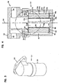
- the reference numeral 51 generally designates a liquid filter assembly according to the present disclosure.
- Liquid filter assembly 51 generally includes a filter head 53 and a filter housing 54.
- the particular liquid filter assembly 51 includes a removable and replaceable (i.e., serviceable) filter cartridge 55 is positioned within the housing 54 ( Fig. 4 ).
- the liquid filter assembly 51 may be configured for a variety of liquid filter operations; for example, as a lubricating oil filter, a hydraulic fluid filter or as fuel filter.
- the particular liquid filter assembly 51 depicted is configured for use as oil filter assembly 58, with out-to-in flow.
- the basic principles described, and componentry shown can be applied in the instance of other types of, or configurations of, liquid filters, including ones configured for in-to-out flow.
- liquid to be filtered enters the filter head 53 (from a flow circuit within the equipment) and passes through the filter head 53, via inlet channel 60.
- the channel 60 is configured to provide for an annular flow of inlet liquid.
- the liquid then flows into the housing 54, specifically into annular region 62, surrounding cartridge 55 between cartridge 55 and sidewall 54a of housing 54.
- the liquid flows through cartridge 55 and into central clean liquid volume 66.
- the liquid then exits volume 66 in the direction of arrow 68, into an outlet flow channel 69, in filter head 53.
- the outlet flow channel 69 would then provide fluid flow communication with appropriate equipment on which the filter head 53 is mounted.
- Such equipment could include, for example, a vehicle, or various construction equipment or other equipment (stationary or mobile).
- the housing 54 is openable. Referring to Fig. 4 , in the instance of liquid filter assembly 51, the housing 54 is openable by separating the housing 54 from filter head 53, at threads 70. A seal 71 to prevent leakage is provided by an o-ring.
- filter media 75 in filter cartridge 55, will become occluded due to build up in (or on) the media 75 of contaminants filtered from the liquid flow.
- the media 75 is generally serviced, by replacement.
- service of media 75 is accomplished through removal and replacement of serviceable cartridge 55.
- the typical serviceable cartridge 55 generally comprises the media 75, positioned to extend between first and second, opposite, end caps 77, 78.
- the end caps 77, 78 may be constructed from a variety of materials, for example they may be molded from a polymer or they may be configured from metal, for example with the media secured thereto.
- the end caps 77, 78 are shown as molded end caps made from an appropriate polymeric material.
- the media 75 is a pleated media cylinder 75a, defining inner pleat tips or edges 75b, and outer pleat tips or edges 75c, Fig. 5 .
- the pleats extend axially, between the end caps 77, 78, Fig. 4 .
- the filter cartridge 55 is a "double open end” filter cartridge 55a.
- each of the end caps 77, 78 is an “open” end cap 77a, 78a, each having a central aperture (77b, 78b respectively) therethrough, positioned for fluid flow communication with central region 66.
- a reason that the filter cartridge 55 is a "double open end" filter cartridge 55a is that, during servicing, it is slid over support tube 79.
- the support tube 79 is discussed in greater detail below. In the example shown, support tube 79 remains affixed to the bowl or housing 54, during a service operation in which the filter cartridge 55 is removed and replaced. Of course in alternate systems, the support tube could be constructed to not be permanently positioned in the housing.
- the seal arrangement comprises a first seal 82 and a second seal 83.
- the first seal 82 is positioned for sealing between the end cap 77 of cartridge 55 and portion 85 of filter head 53; and, the second seal 83 is positioned to provide a seal between end cap 78 of the cartridge 55 and portion 86a of housing 54.
- seal 82 comprises an o-ring 82a, Fig. 5 , mounted on an axially directed seal support 82b which extends axially outwardly from end cap 77.
- seal 83 comprises an analogous o-ring mounted on an axially directed extension, extending axially outwardly, away from the media 75, from end cap 78.
- portion 85 of filter head 53 is an outside surface portion of a center liquid flow exit tube 85a ( Fig. 5 ); and, portion 86a of housing 54 ( Fig. 4 ) comprises a portion of a housing base 86.
- Outer sidewall 54a, of housing 54 projects (in the embodiment of Figs. 3-5 ) upwardly toward filter head 53 from base 86.
- Inner liner, tube or core 79 is secured to housing base 86.
- a filter cartridge such as filter cartridge 55, Figs. 4 and 5 will be characterized herein as a "coreless cartridge,” since it contains (as an integral component of the filter cartridge) no inner liner, tube or core, to support axial load, secured permanently therein, in extension between end caps 77, 78.
- coreless in this context is meant to refer to arrangements that do not have as an integral part therein, an inner tubular support for axial load (as opposed to having no type of support at all).
- the media could have a pleated extension of light wire mesh or plastic mesh along an inside thereof, and it would still be “coreless” in accord with this definition.
- the filter cartridge In general, if structure integral with the filter cartridge along an inside of the media capable of supporting an axial compressive load of at least 20 lbs. (9.1 kg), is not permanently present in the filter cartridge, the filter cartridge will be considered “coreless” in accord with this definition.
- the term "axial” in this context meaning force in the direction of extension of axis 94, Fig. 4 ; i.e., a direction between the opposite end caps 77, 78.
- a filter cartridge will be considered “coreless” within the above definition, even if a core not permanently installed in the cartridge itself, is present elsewhere in the assembly 51.
- the filter cartridge 55 also includes no integral outer support structure, to support axial load, extending continuously between the end caps 77, 78.
- Such an arrangement will be referred to herein as an "outer axial load liner free" filter cartridge or as a filter cartridge with no axial load outer liner.
- a filter cartridge will be considered to have no outer axial load liner or to be outer axial load liner free, even if it contains (integral with the filter cartridge) a pleated light mesh such as a light wire mesh or light plastic mesh or other structure around the outside, that does not significantly resist compressive axial load.
- a filter cartridge will be considered to be outer axial load liner free, as long as any outer liner present (integral with the filter cartridge) is not capable of supporting an axial load of at least 20 lbs (9.1 kg).
- the filter cartridge is both outer axial load liner free and coreless, it may sometimes be referred to herein as "axial load liner free.”
- inner core 79 is a porous tubular member 91, Fig. 5 , positioned within liquid filter assembly 51 such that, during a service operation to replace the serviceable cartridge 55, the porous tubular member 91 is not removed and replaced. That is, the serviceable cartridge 55 is coreless, because the inner core 79 (i.e., the porous tubular member 91) is not part of the filter cartridge 55.
- the inner core 79 is secured to a remainder of housing 54, Fig. 4 .
- a particularly convenient method of providing for a secure fit is to optionally use, as the tubular member 91, Fig. 4 , a member that is not radially continuous, but rather has a gap or open seam 93, Fig. 5 , therein.
- the particular seam 93 shown is not axial, but rather extends at an angle (A) to central axis 94, Fig. 5 in accord with a similar liner (but integral the filter cartridge) shown in U.S. Patent 6,206,205 .
- the gap presented by seam 93 allows the perforated tubular member 91 to be radially compressed (under pressure) somewhat, to a smaller circumference, and thus it can be secured by press fit into a receiver 95 in base 86 of housing 54.
- a typical gap will be selected to have an angle A of no more than 15°, preferably at least 0.5°, typically 1° to 15°.
- the outside diameter for the inner core 79 is selected such that cartridge 55 can be slid thereover, in use.
- the outside diameter of the support 91 is of a size such that it will operate as an inner radial support to the pleated media 75a.
- the OD of tubular support should preferably be chosen to be no more than 0.09 inches (2.3 mm) from the ID of the inner pleat tips 75b of pleated media 75a.
- the porous tubular member 91 can be provided with bumps, ribs or other constructions on an outer surface thereof, to provide for closer engagement to the inner pleat tips 75b.
- the tubular member 91 may comprise metal or a molded plastic.
- end cap 77 will be referred to herein as an "upper" end cap since in the normal installation position, Fig. 4 , end cap 77 is positioned directed upwardly.
- end cap 78 will generally be referred to herein as a lower or bottom end cap, since in a normal installation position of Fig. 4 , it is directed downwardly.
- End cap 78 can be configured to include a contaminant containment and collection feature, not shown thereon.
- the contaminant containment and collection feature may be according to PCT Publication WO 02/081052 published October 17, 2002 .
- the filter cartridge 55 in order for liner 91 to provide for axial support between end caps 77, 78, during a normal use, it is preferable to construct the filter cartridge 55, such that, between the end caps 77, 78, (i.e., on the filter cartridge 55 as a whole, during use), there is little or no net surface axial force on the element 55; and also such that there is little or no net surface axial force on each end cap 77, 78.
- end caps 77, 78 are selected. It is the location of these seals, which will generate a preferred force profile at end cap 78, and will thus allow for little or no net force on filter cartridge 55, or net surface force on each end cap 77, 78.
- the seal location for end cap 77 is at 82.
- the seal location for end cap 78 is at 83.
- Ds the diameter of a seal
- Di The inside diameter defined by the pleats
- Do The outside diameter defined by the pleat tips
- Db the diameter of a seal which, for that end cap, provides for a balance of forces or a net axial surface force on that end cap, will be referred to as Db or DsB.
- diameter DbA can be identified such that in normal use the surface axial forces toward the outer surface of the end cap A and the inside surface of the end cap A are in balance. That is, a seal having a diameter DbA is one that would provide for no net surface axial forces operating on the associated end cap A, in use.
- each end cap will be in balance with respect to net surface axial forces, and there will be no net surface axial force operating on the associated cartridge. This would be the case even if one of the end caps is closed, and thus does not require the seal to protect against unfiltered liquid from entering the internal volume of the filter cartridge. That is, even with a closed end cap, a seal can be provided engaging that end cap with a portion of the housing. This seal would separate regions subjected to Pu from regions subjected to Pd. Thus, its location could be provided at a balance point Db. However this unique latter seal would not be used to protect against unfiltered flow by-passing the media.
- the diameter Ds of a seal which provides for a balance of forces against each surface of an associated end cap is generally referred to as Db.
- An end cap A will be considered to be within a preferred level of balance, with respect to net axial surface forces, for a typical liquid filter cartridge, provided the seal diameter Ds is at a diameter within plus or minus 15% of DbA, i.e., within the range of 0.85 - 1.15 DbA, inclusive.
- the seal diameter Ds is within the range of 0.9 - 1.1 DbA, inclusive, often 0.92 - 1.08 DbA. Most typically it will be selected to be within the range of 0.95 - 1.05 DbA, inclusive. As discussed below, the principles described herein can be applied outside of these ranges, however.
- the seal location will be positioned outwardly from the inner pleat diameter (Di) at least 2 mm, often at least 5 mm, and sometimes at least 10 mm; and, also be at a location recessed from the outer pleat diameter (Do) at least 2 mm, often at least 5 mm and sometimes at least 10 mm. Preferred locations can be calculated for any given system, as discussed below.
- At least a first open end cap configured for fluid flow into and out of the element will have a seal diameter Ds as defined above. This would correspond to end cap 77, Fig. 3 . Most preferably both end caps (77, 78) have a seal diameter as defined above.
- a liquid filter arrangement 200 comprising a filter base 201 and a removable cover 202.
- a filter cartridge 205 Secured within housing 203 formed by cover 202 and base 201, is a filter cartridge 205.
- the filter cartridge 205 comprises pleated media 206 in extension between opposite end caps 207 and 208.
- End cap 207 is an open end cap, the radial seal indicated at 210 formed by an o-ring 211 mounted on an outwardly directed (relative to the media) axial extension 212 of end cap 207.
- a seal 215 is shown formed by an o-ring 216 mounted on an outwardly directed axial extension 217 of end cap 208.
- seal 210 is provided between o-ring 211 on end cap 207 and a portion 220 of support liner 221. It is noted that seal 215 is formed between o-ring 216 on a portion of end cap 208, and a portion 225 of base 203.
- the assembly 200 is a top load arrangement, and includes a drain arrangement 230, to allow standing liquid to drain from interior 231, as cover 202 is being removed.
- a drain arrangement 230 to allow standing liquid to drain from interior 231, as cover 202 is being removed.
- seals 210 and 216 are each positioned at a location for a balanced seal diameter, Db (i.e., each is within 0.85 - 1.15 Db), in accord with the above definitions.
- liquid filter cartridges can be located in any position relative to gravity, for the sake of the simplicity, the concepts will be discussed assuming an axis of the filter cartridge normal to the plane of the earth.
- forces acting toward the earth (downward) will be defined as negative (-), and opposite forces as positive (+).
- the filter cartridge is cylindrical, utilizes pleated media, and has end caps which are circular.
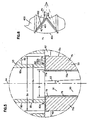
- Fig. 6 illustrates a portion of a filter cartridge.
- An end cap is shown at 400, and the pleated media at 401.
- the geometry of the pleated media 401 is configured in a "V" shape.
- the arc A-B describes one complete pleat.
- Pu is the upstream pressure
- Pd is the downstream pressure. Because the thickness of the media 401 is small compared to the overall area of media, it is assumed that the pressure drop across the media occurs at the media centerline 402 and is a step function. This assumption means that the pressure on the upstream side of the media 401a is considered to remain constant through the first half of the media thickness; and, that at a centerline of the media thickness the pressure drops to that of the downstream pressure and remains constant through the last half of the media to the downstream side 401b.
- the end cap 400 under consideration is an open end cap, having an outside edge 404 and an inside edge 405 corresponding to the outer (Do) and inner (Di) pleat tips, respectively.
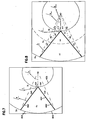
- Fig. 7 the illustration in Fig. 6 has been modified to calculate the areas effected by the pressure drop.
- a centerline 402 of the media 401 is used rather than the full media thickness (as explained above).
- Au is the area of the upper end cap 400 that is subject to the upstream pressure on both sides of the end cap 400. Because of this the pressure on both sides cancel each other out and do not contribute to the net surface axial compressive force that is applied to the corresponding end cap or filter cartridge.
- Ad1 + Ad2 is the combined area on the upper end cap that is subject to upstream pressure (Pu) on the outside surface of the end cap and to downstream pressure on the inside surface of the end cap. This combined area relates to one complete pleat.
- Ad 1 + Ad 3 Di 2 ⁇ Do 2 ⁇ Sin ⁇ a 0 2
- Ad 1 + Ad 3 Di 8 ⁇ Do ⁇ Sin 180 0 PC
- Ad 3 Di 2 8 ⁇ ⁇ PC
- Ad 1 Di 8 ⁇ Do ⁇ Sin 180 0 PC - Di 2 8 ⁇ ⁇ PC
- Ad 1 Ad 2
- Ad 1 Ad 2
- Example 1 A Filter Cartridge with Conventional ID Seals.
- a filter cartridge confirmation considered in this example is one which is similar to Fig. 1 , except it has two opposite open end caps singular to end cap 5, and has an outside pleat diameter (Do) of 4 inches (101.6 mm); an inside pleat diameter (Di) of 2 inches (50.8 mm); a pleat count (PC) of 40; and, a pressure drop ( ⁇ P or PD) across the media of 100 psid (6,895 bar) in use.
- Areas Ad1 and Ad2 are on the downstream side of the media. By placing the seal on the outside diameter of the lower end cap, the downstream pressure Pd now acts on both sides of the areas Ad1 and Ad2; thereby canceling each other out resulting in a net axial force of zero acting on those areas.
- Ad 1 Ad 2
- Ad 3 + Ad 4 Di 2 4 ⁇ ⁇ PC
- the net surface force on the lower end cap, not counting the force from the upper end cap, with the seal on the outside diameter, is acting in the opposite direction of the force that is acting on the lower end cap of the conventional design. Also, the magnitude of the force is larger than on the conventional design.
- One approach would be to decrease the diameter of the seal on the lower end cap such that the net axial forces on the lower end cap would be zero.
- the force on the upper end cap Ftu operating in a downward direction would ensure that the filter cartridge would bottom out against a bottom of the housing. Reducing the seal diameter further would cause the net force to begin to increase in an upward direction. Continuing to reduce the seal diameter will eventually reach a point where this diameter is the same diameter as the seal on the upper end cap, which would have axial forces the same as on a conventional filter cartridge.
- An electronic spreadsheet can be used to explore various diameters and forces to achieve a specific result.
- Fig. 8 one can see that it is similar to Fig. 7 except that an additional diameter Ds has been added. This is the seal diameter on the lower end cap shown at a diameter other than at the outside or inside diameter.
- Ad1 and Ad2 are now divided into three sections each A2, A6, & A8 for Ad1 and A3, A5, & A7 for Ad2.
- the areas of interest are A2, A3, and A4.
- upstream pressure, applied to A1 is outside the diameter Ds of the seal. This means that the pressure on both sides of A1 are the same and therefore cancel each other out. This same condition, on the downstream side, can be found for areas A5, A6, A7 & A8.
- a 1 .008727 ⁇ a 0 ⁇ D ⁇ o 2 2 - A 4 - 2 Di 2 ⁇ Do 2 ⁇ Sin ⁇ a 0 2
- a 1 .004364 ⁇ a 0 ⁇ Do 2 - A 4 - .25 Di ⁇ Do ⁇ Sin ⁇ a 0
- a 2 .002182 ⁇ a 0 ⁇ Do 2 - Ds 2 - .002182 ⁇ a 0 ⁇ Do 2 + A 4 2 + .125 Di ⁇ Do ⁇ Sin ⁇ a 0
- both areas A2 and A4 are known in terms of known parameters (Do, Di, number of pleats).
- A2 A3; that the upstream pressure Pu acts on the area A4, while the downstream pressure Pd acts on the areas A2 and A3; and that on the rest of the areas (A1, A5, A6, A7, and A8) the pressure on either side of the end cap is the same and therefore cancel each other out in the axial direction.
- lab testing can be used to evaluate the net axial load on the element.
- a load cell can be placed on the inside diameter of the filter cartridge.
- One end of the load cell would be attached to the upper end cap, the other end attached to the lower end cap.
- the filter cartridge would be placed into the filter housing. Oil, at a standard test flow, would pass through the filter cartridge. Test dust or other contaminant would be injected upstream of the filter cartridge.
- pressure drop across the filter would increase, thereby increasing the axial load in the filter cartridge.
- a filter cartridge using a standard sealing arrangement will generate an axial force on the load cell. This force will increase in proportion of the pressure drop across the filter.
- a filter cartridge using the preferred seal arrangements characterized would have resolved all or most of the axial forces on the filter cartridge. This would be assessed, as the pressure drop would increase across the media, by observations of relatively little, if any, increase on the axial force of the load cell.
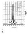
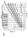
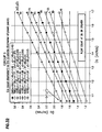
- Fig. 11 the number of pleats is plotted on the X axis, and the Y axis represents unit axial load.
- the dimensions refer to Fig. 10 . It can be seen that above a pleat population of about 20, for example 20-30, there is relatively little change in axial load, as the number of pleats change.
- arrow X indicates a direction of out-to-in flow or standard (std) flow.
- Arrow Y indicates a direction of in-to-out flow or reverse (rev) flow.
- Dimension Z indicates pleat depth.
- DsB Do ⁇ Di ⁇ Sin / PC 180 ⁇ PC ⁇
- PC 50
- DsB represents the tube outside diameter that seals on the I.D. of the o-ring.
- the following equation will calculate the amount of axial load (Fa) that will be applied to the media pack. To do this one needs one more piece of information; the pressure drop (PD) across the media pack. For this example 200 psid (13,790 bar) will be used (many hydraulic filter cartridges are designed to withstand up to 200 psid (13,790 bar)).
- Fa .25 ⁇ PD ⁇ ⁇ Ds 2 - PC ⁇ Di ⁇ Do ⁇ Sin / PC 180
- the minus (-) indicates the media pack is under compression.
- annular gap that is critical to the structural integrity of the filter cartridge (Gap 2).
- This annular gap is formed by the inside diameter of the media pack and the outside diameter of the liner.
- the primary job of the liner is to provide radial support to the media.
- the pressure drop across the media creates a force on the media that is directed radially inward.
- the liner supports the media against the force. If there is a gap between the I.D. of the media pack and the O.D. of the liner, the media pack will have to move the distance of the gap before the liner can provide any support. Because the media is somewhat flexible, a certain amount of gap is acceptable. If the gap becomes too large the media will flex too much and will prematurely fail.
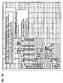
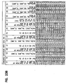
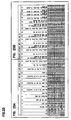
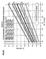
- Fig. 14 a graph is presented showing a plot of Di vs. Do, for: a given pressure (PD) max (200 psig (13,790 bar)); defined acceptable force max on the filter cartridge (40 pounds of force) (177.928 864 N) a defined Ds; a defined pleat count; and a defined maximum effective area that the pressure can differential can act upon, Ae.
- PD pressure
- PD max 200 psig (13,790 bar
- defined acceptable force max on the filter cartridge 40 pounds of force
- 177.928 864 N a defined Ds
- a defined pleat count a defined maximum effective area that the pressure can differential can act upon
- Ae This figure (Ae) of course would be zero, if the seal was specifically at Db.
- Ae is the amount of area the pressure differential can act upon to stay within the limited force range desired.
- the pressure differential max is identified as 200 psid (13,790 bar), the force max acceptable on the filter cartridge is 40 pounds of force (177.928 864).
- the pleat count was fixed at 50, initially Do at 3.27 inches (83,1 mm) and Di at 1.59 inches (40,4 mm).
- Ds was calculated as being at 2.28 inches (57,9 mm), for Db.
- Do could be changed, and what its ultimate affect on the force. Do could be increased to 3.43 inches (87,1 mm), maintaining Di and Ds fixed, with the force max going up to 40 pounds (18,14 kg). Do could be decreased to 3.11 inches (80,0 mm), with Di and Ds fixed, the force max changing to 40 pounds (18,14 kg) in the opposite direction.
- Di could be moved up to a maximum of 1.67, while maintaining the force and no higher than 40 pounds (18,14 kg). Di could be decreased to 1.51 inches (38,4 mm), with a force going up to 40 pounds (18,14 kg) in the opposite direction.
- the next two lines indicate how the seal Ds could be moved, with Do and Di figures fixed.
- the seal can be moved down to 2.22 inches (56,4 mm), with the force not exceeding the 40 pound (18,14 kg) range; and the seal could be moved up to 2.33 inches (59,2 mm), with the seal not exceeding the 40 pounds (18,14 kg).
- the lower table shows a calculation for an element having a different size assumed.
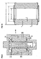
- the cartridge 500 comprises pleated media 501 extending between first and second opposite end caps 502, 503.
- the particular construction is coreless, and has no inner core or outer core.
- End cap 502 is open, with aperture 505 therein.
- End cap 503 is also open.
- seal support 506 Projecting axially outwardly from cap 502 is seal support 506 with seal 507 thereon. Seal 507 is configured for radial sealing in an inward direction.
- seal support 510 Axially projecting outwardly from end cap 503 is seal support 510 with seal 511 thereon.
- Seat 511 is also configured for sealing radially inwardly.
- the outside pleat diameter (M) being 83.0 mm
- the inside diameter of the pleats (N) being 40.5 mm
- the pleat depth (O) being 21.3 mm
- the seal diameter Ds (indicated at Q) is 57.9 mm, for each of seals 507, 511. In this instance Ds corresponding to Q, would be Db.
- the pleat length is 279 mm.
- the cartridge 500 further includes a contaminant and containment collection feature 530.
- the feature comprises an extension 531 having media 532 therein.
- cartridge 500 is shown installed in an overall filter arrangement 540 comprising a housing S41 secured to a filter head 542.
- Seal 507 is shown sealing to structure 545, in this instance a portion of an inner pipe or core arrangement 546.
- Seal 511 is shown secured to a portion of housing base 550.
- portion 550 is secured to a remainder of the housing S41 by bolts 542'.
- portion 550 is an adaptor positioned in housing 541, at a bottom thereof, to accommodate seal 511.
- Portion 550 also helps center cartridge 500 in housing 541, during installation.
- the present disclosure provides for a variety of alternate configurations for filter cartridges, from conventional ones. Preferred ones have been previously described, in which one or more seal locations are defined with respect to Db, or in general with respect to location were certain surface axial forces will result in use, in the corresponding end cap.
- ⁇ P max for many lube systems would be lower than the 200 psid (13,790 bar) for hydraulic systems, for example in the range of 100 - 150 psid (6,895 -10,342 bar).
- F max again would be a function of the materials chosen. It could be -40 lbf, but could have other values as well.
- seal diameter is meant to refer to the diameter of the interface between the seal ring and the corresponding housing component, when the cartridge is in place.
- the present disclosure relates to overall filter assemblies, having cartridges as characterized herein within them.
- the overall filter assemblies may be configured for top load or bottom load.
- the features of the assemblies may be in accord with the general features characterized in the descriptions and/or examples above.
- the liquid filter assemblies may, again, be configured, for example, as oil (lube) filters, fuel filters or hydraulic filters.
- the methods of assembly generally involve configuring components in accord with the descriptions herein.
- the methods of use generally involve directing liquid flow through a serviceable filter cartridge constructed in accord with the principles described herein, with net effects as characterized resulting.
- a seal between the cartridge and the housing base also provides for centering, during servicing.
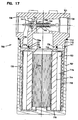
- the reference numeral 600, Fig. 16 generally indicates a liquid filter arrangement according to a further embodiment of the present disclosure.
- the arrangement 600 includes a filter head 601 and a removable liquid filter assembly 602.
- the filter assembly 602 comprises an outer wall 603 and an internal cartridge 604.
- the particular liquid filter assembly 602 depicted is a "spin-on" assembly, meaning that the componentry 602 is generally removed and replaced during a service operation. That is, the cartridge 604 is generally received in the housing 603 such that when the housing 603 is disconnected from the filter head 601, in use, servicing involves replacement of the liquid filter assembly 602 with a new housing 603 and new cartridge 604, previously assembled together. That is, the cartridge 604 is not removed from housing 603 during servicing.
- the cartridge 604 comprises media 605, in this instance pleated media 606 extending between first and second opposite end caps 607, 608 respectively.
- End cap 608 is a closed end cap, shown supported on support structure 610 within bottom 611 of housing 603.
- the cartridge 604 includes an inner liner at 604a.
- End cap 607 is an open end cap, having flow aperture 615 therethrough.
- End cap 607 includes seal support arrangement 617 supporting o-ring seal 618, for sliding over post 620 during installation, and sealing around post 620 during use.
- End cap 607 further includes outwardly projecting flange 625, which can be in positioned to engage structure on housing 603, to inhibit removal of cartridge 604 from housing 603, after initial installation.
- the seal 630 defined in this instance by o-ring 618 has a sealed diameter Ds located, for example, at or near the balance point Db, discussed previously.
- End cap 608 is supported against motion downwardly in the direction of arrow 635, by supports 610.
- Assembly 600 is configured for out-to-in flow, with flow of unfiltered liquid to be filtered into the head 601 occurring at 644, and then through entry 643 into annulus 641 around filter cartridge 604. The liquid would then filtered, by passage through the media 606 into inner region 606a. The filtered liquid would then flow into channel 620a in head 601, and outwardly through outlet flow exit 640.
- Post 620 includes stop 645 thereon, which will be engaged by seal support arrangement 617, should the cartridge begin to slide in the opposite direction of arrow 635, under the biasing forces indicated.
- the location of seal 630 can be positioned essentially at a balance point D b , so there would be no upper or downward forces from the liquid pressure differential on the end cap 607, if desired.
- the seal 630 can be positioned alternately, within the range of locations around D b , as described herein.
- spin-on assemblies analogous to assembly 602 could be configured for "in-to-out” flow, across the media pack 604, if desired.
- liquid filter arrangement 700 is depicted comprising a filter head 701, a removable housing 702 and a filter cartridge 703.
- the cartridge 703 is a serviceable cartridge, that can be removed and replaced by disconnecting housing 702 from head 701, at threads 710, replacing the cartridge 703 within bowl 702, and then remounting bowl 702 on head 701.
- Seal 711, 712 are shown to inhibit leakage outwardly from bowl 702.
- the cartridge 703 is shown configured for in-to-out flow, although alternate configurations are possible.
- the cartridge 703 comprises media pack 714, in this instance comprising pleated media 714a, extending between upper end cap 715 and lower end cap 716.
- lower end cap 716 is closed.
- an outer support 718 which can comprise a coiled roving or liner, as desired.
- End cap 715 is open having central aperture 715pa. End cap 715 further includes seal support 720 thereon, supporting seal member 721, in this instance comprising o-ring 721a.
- the cartridge 703 is positioned with seal member 721 sealed against post 730 in which flow aperture 730a is provided, in communication with open interior 703a of cartridge 703.
- Assembly 700 includes a bypass valve arrangement 740 therein, allowing for a liquid flow to bypass cartridge 703, should the cartridge 703 become sufficiently occluded.
- the bypass valve 740 comprises a valve head 741 maintained closing aperture 742 by biasing arrangement 743 comprising in this instance a coiled spring 744.
- the seal support 720 is shown positioned on end cap 715, at a location appropriate to support the seal arrangement 721 and sealing against post 730, at a location either corresponding to Db, or modified from Db as described herein.
- Do is provided a selected outside diameter of the pleat pack.
- the outside diameter of a pleat pack having pleated media is the diameter defined by the pleat tips.
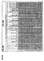
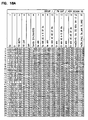
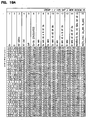
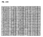
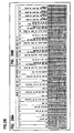
- Do is ranged from 2.5 inches (63.5 mm) up to 5.5 inches (139.7 mm) in 0.1 inch (2.54 mm) increments, herein these are called “Group 1.”
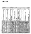
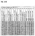
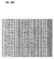
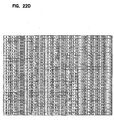
- Figs. 21-23 Do is ranged from 5.6 inch (142.2 mm) to 10 inch (254 mm) in 0.1 inch (2.54 mm) increments, herein these are sometimes called “Group 2.”
- Do is ranged from 1.5 inch (38.1 mm) to 2.4 inch (61 mm) in 0.1 inch (2.54 mm) increments; these are sometimes called "Group 3.”
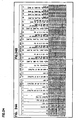
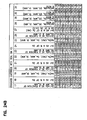
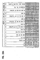
- the grouping of Group 1, Group 2 and Group 3, for the tables of Figs. 18-26 is a grouping based on selected outside diameter or size, for consideration.
- the groups are not meant to be otherwise significantly distinct.
- the transitions between the group are not intended to be discounted.
- the graphs can b considered as continuous across all regions identified.
- the groupings could be of some assistance in considering application of the techniques described herein, to liquid filter applications, since the groupings do generally relate to small, medium and large size filter cartridges.
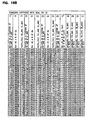
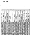
- the fourth column in the table entitled “Plt Cnt” refers to the number of pleats or pleat count, for the example. As previously discussed herein, once the pleat count has reached 20, in general addition of still more pleats does not change significantly the calculation of Db. Thus, for the examples analyzed in the tables of Figs. 18-26 , the pleat count in all instances was set at 20.
- the next column in the tables of Figs. 18-26 is termed "Gap.”
- the "gap” is a variable selected, for purposes of the calculations reported in Figs. 18-26 , as an amount that Do and Di will be varied against the fixed seal location of col. 6 for comparison discussed below.
- the seal location when at Db is at a position spaced across the end cap from each pleat tip edge.
- Db col. 6
- Do min The seventh column in the tables of Figs. 18-26 is entitled "Do min.”
- Do min is meant to indicate a variation in the cartridge of the identified line, in which Do has been reduced by the selected "Gap” of col. 6, even though Di and seal location (Ds) have remained fixed.
- Do min (1-Gap)x Do.
- Do min (1- .07)(2.5); i.e., 0.93 (Do) or 2.33 inch (59,2 mm).
- Do min (col. 7) is stated as a percent of Db (col. 6). That is, the value on the table is equal to Do min/Db.
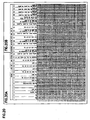
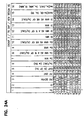
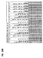
- Do max (1 +Gap) x Do.
- Do max (1 + .07) x 2.5, i.e., 1.07 (2.5) or 2.68 inch (68,1 mm).
- the tenth column reflects Do max (col. 9) as a % of Db (col. 6). Thus the value given equals Do max/Db.
- Di min (1-Gap) x Di.
- Di min (1-.07) x 1.25; i.e., 0.93 (1.25) or 1.16 inch (29,5 mm).
- Column 12 is a report of Di min (col. 11) as a % of Db (col. 6). Thus, the values in column 12 for any given line comprise Di min/Db.
- Di max (1+Gap) times Di.
- Di max (1+ .07) x 1.25; i.e.,1.07 (1.25) or 1.34 inch (34,0 mm).
- column 15 is a calculated value, using the functions described previously herein.
- the absolute value of this can be compared to the value of column 15, to see whether the amount of total effected area (Ae) is smaller, and thus better, by comparison to a standard filter cartridge.
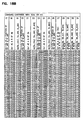
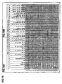
- the pressure is away from the pleat pack (when an out-to-in flow is assumed). In the calculation, a pleat count of 20 is used.
- Column 27 is a calculated value of the seal side of column 26 divided by the value of Db in column 6.
- the area Ae is 79% of Astd. This means that the axial load is also 79% of the axial load on the corresponding standard filter cartridge.
- the area Ae is 10% of Astd. This means that the axial load is also 10% of the axial load on the corresponding standard filter cartridge.
- the area Ae is 10% of Astd. This means that the axial load is also 10% of the axial load on the corresponding standard filter cartridge.
- the area Ae is 98% of Astd. This means that the axial load is also 98% of the axial load on the corresponding standard style cartridge.
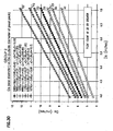
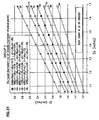
- Figs. 27-32 the groups refer to groups of seal diameter (Ds) resulting from the data of Figs. 18-26 .
- the graph includes a plot of certain information included in tables of Figs. 18-20 .
- the plot of Fig. 27 is of the seal diameter Ds against Di. Seven lines are plotted. The lines are identified as A, B, C, D, E, F and G as follows:
- the plot of Fig. 28 is of the seal diameter Ds against Do. Seven lines are plotted. The lines are identified as A1, B1, C1, D1, E1, F1 and G1 as follows:
- Fig. 29 is of the seal diameter Ds against Di. Seven lines are plotted. The lines are identified as A2, B2, C2, D2, E2, F2 and G2 as follows:
- the plot of Fig. 30 is of the seal diameter Ds against Do. Seven lines are plotted. The lines are identified as A3, B3, C3, D3, E3, F3 and G3 as follows:
- Fig. 31 is of the seal diameter Ds against Di. Seven lines are plotted. The lines are identified as A4, B4, C4, D4, E4, F4 and G4 as follows:
- the plot of Fig. 32 is of the seal diameter Ds against Do. Seven lines are plotted. The lines are identified as A5, B5, C5, D5, E5, F5 and G5 as follows:
- the liquid filter arrangements generally comprise media extending between first and second opposite end caps.
- the media would typically be pleated, defining an inner pleat diameter (Di) and an outer pleat diameter (Do).
- One or both of the end caps can have an open central aperture.
- At least one of the end caps would have a seal support positioned on a projection extending axially outwardly from the end cap (in a direction away from the media).
- the seal supported by the seal support is an o-ring, although alternatives are possible.
- the seal can be supported to be directed inwardly or outwardly.
- the o-ring or alternate seal would generally define a seal diameter Ds.
- the filter cartridge can be used as a serviceable filter cartridge, in which it is removed and replaced from a housing during use. It also can be contained permanently within a housing, to be replaced with the housing part, during servicing.
- the typical seal support shown in the drawings herein is of a type which slides into position over (or inside of) a liquid filter assembly component during use.
- the seal supports are shown slid over a post or other structure, through which an aperture, or flow conduit extends.
- the seal support can slide inside of a flow aperture, to seal against the wall defining the flow aperture, in use.
- Seal supports of the type shown in the descriptions herein are generally put in position without an external clamp, such as a hose clamp or similar structure, to secure the seals in place. Such arrangements will sometimes be described herein as “non-clamp” or “non-clamping” seal supports or seal arrangements, or by similar terms.
- the pleated media includes, on one or both sides thereof, pleated media support, such as a pleated wire mesh support or a pleated plastic mesh support.
- both end caps can be provided apertures therein, and both end caps can be provided with seals thereon within a similar definition.
- a seal support for a seal member having a seal diameter DsB within the range of 0.85 - 1.15 DbB, typically 0.9 - 1.1 DbB and often within the range of 0.95 - 1.05 DbB.
- the filter cartridge is such that at least on a first end cap having a central aperture, seal support is provided that is spaced across the end cap, from the inside diameter of the pleat tips (and end cap aperture if present) a distance corresponding to at least 0.1 X, where X is the dimension corresponding to the distance between the outside diameter of the pleat tips (or end cap outer perimeter if similar) and the inside diameter of the pleat tips (or end cap aperture if similar and present).
- the seal arrangement is also positioned on the end cap a distance spaced from the outer pleat tip diameter (or end cap outer perimeter if similar), inwardly, a distance also corresponding to at least 0.1 X.
- a similar definition can be provided for the second end cap, whether open or closed. That is, a seal arrangement can be mounted on the second end cap defining a seal diameter spaced outwardly from the inside pleat diameter (or aperture) and inwardly from the outside pleat diameter (or end cap perimeter) a distance corresponding to at least 10% of the difference between the inside pleat diameter (or aperture) and outside pleat diameter (or aperture).
- the end cap aperture diameter of an open end cap will be approximately the same as (or only slightly smaller than) the inner pleat tip diameter. Also in some instances the outside end cap diameter would be about the same as the outside pleat diameter. However variations are possible.
- the spacing should typically be considered with respect to the pleat tip inner diameter and outer diameter, since these factors control Ae.
- the liquid filter cartridge is provided with advantage, over a liquid filter cartridge in which the seal is provided on either the inside pleat diameter or the outside pleat diameter, by having the seal supported at a location spaced from both the side pleat diameter and outside pleat diameter a distance of at least 5 mm, typically at least 10 mm, and usually at least 15 mm.
- a filter cartridge typically with a pleat count of 20 or greater, can be constructed which has first and second end caps and pleated media extending therebetween, defining an inner pleat tip diameter (Di) and an outer pleat tip diameter (Do) for a given Ds located spaced between the Di and Do location, wherein: for a given value Ds within the range of 1.06 inches (26.9 mm) to 7.06 inches (179.3 mm);
- liquid filter assemblies comprising housings with filter cartridges therein (serviceable or otherwise).
- the housing would be configured to support the filter cartridge, and the filter cartridge would be selected in accord with the general principles discussed herein, for example as indicated above in Sections IX A-F.
Claims (4)
- Ensemble de filtre à liquide comportant :(a) une tête de filtre comprenant un canal d'entrée configuré pour un écoulement annulaire de liquide d'entrée ;et un canal de sortie ;(b) un boîtier de filtre comprenant un noyau interne comportant un élément tubulaire poreux ;(i) le boîtier de filtre pouvant être ouvert en séparant le boîtier de filtre de la tête de filtre au niveau de filetages ; et,(c) une cartouche de filtre à liquide, positionnée de manière amovible dans le boîtier de filtre avec :(i) des premier et deuxième bouchons d'extrémité opposés ;(A) le premier bouchon d'extrémité ayant une première ouverture centrale à travers ; et,(B) le deuxième bouchon d'extrémité ayant une deuxième ouverture centrale à travers ;(ii) une extension de matières filtrantes fixée sur, et s'étendant entre, les première et deuxième bouchons d'extrémité ;(A) l'extension de matières filtrantes comportant une matière plissée définissant un volume central ouvert en communication d'écoulement de fluide avec les première et deuxième ouvertures centrales ;(B) les matières filtrantes comportant un total d'au moins 20 plis ;(iii) un premier support de joint d'étanchéité dépassant axialement vers l'extérieur du premier bouchon d'extrémité ; et un deuxième support de joint d'étanchéité dépassant axialement vers l'extérieur du deuxième bouchon d'extrémité ;(iv) un premier agencement de joint d'étanchéité comportant un joint d'étanchéité supporté par le premier support de joint d'étanchéité, le joint d'étanchéité étant supporté afin d'être orienté vers l'extérieur ;(v) le premier agencement de joint d'étanchéité étant positionné de façon à procurer un plus grand diamètre de joint d'étanchéité (DsA) qu'un diamètre de la première ouverture centrale ;(A) DsA étant dans la plage de 0,92 à 1,08 DbA inclus, où DbA est un diamètre au niveau duquel il n'y a aucune force axiale nette sur le premier bouchon d'extrémité vers ou à l'écart du deuxième bouchon d'extrémité, pendant l'utilisation ; la force axiale nette étant la force axiale nette agissant sur le premier bouchon d'extrémité, du fait de pressions de liquide contre les surfaces opposées, extérieure et intérieure, de celui-ci et,(vi) un deuxième agencement de joint d'étanchéité comportant un joint d'étanchéité monté sur le deuxième support de joint d'étanchéité et orienté de façon à former un joint d'étanchéité radial ;(vii) le deuxième agencement de joint d'étanchéité étant positionné de façon à procurer un plus grand diamètre de joint d'étanchéité (DsB) qu'un diamètre de la deuxième ouverture centrale ;(A) DsB étant dans la plage de 0,92 à 1,08 DbB inclus, où : DbB est un diamètre au niveau duquel il n'y a aucune force axiale nette sur le deuxième bouchon d'extrémité vers ou à l'écart du premier bouchon d'extrémité, pendant l'utilisation ; la force axiale nette étant la force axiale nette agissant sur le deuxième bouchon d'extrémité, du fait de pressions de liquide contre les surfaces opposées, extérieure et intérieure, de celui-ci.
- Ensemble de filtre à liquide selon la revendication 1 dans lequel :(a) le premier agencement de joint d'étanchéité est un joint torique ;et,(b) le deuxième agencement de joint d'étanchéité est un joint torique.
- Ensemble de filtre à liquide selon l'une quelconque des revendications 1 et 2 dans lequel :(a) la cartouche filtrante a une construction sans âme de charge axiale.
- Ensemble de filtre à liquide selon l'une quelconque des revendications 1 à 3 dans lequel :(a) la cartouche filtrante est sans revêtement extérieur de charge axiale.
Priority Applications (1)
| Application Number | Priority Date | Filing Date | Title |
|---|---|---|---|
| EP10182710.3A EP2301646B1 (fr) | 2004-04-13 | 2005-04-04 | Cartouche de filtration pour la filtration d'un liquide |
Applications Claiming Priority (2)
| Application Number | Priority Date | Filing Date | Title |
|---|---|---|---|
| US56204504P | 2004-04-13 | 2004-04-13 | |
| PCT/US2005/011256 WO2005099861A1 (fr) | 2004-04-13 | 2005-04-04 | Cartouche filtrante pour filtrage de liquides |
Related Child Applications (1)
| Application Number | Title | Priority Date | Filing Date |
|---|---|---|---|
| EP10182710.3A Division-Into EP2301646B1 (fr) | 2004-04-13 | 2005-04-04 | Cartouche de filtration pour la filtration d'un liquide |
Publications (2)
| Publication Number | Publication Date |
|---|---|
| EP1753518A1 EP1753518A1 (fr) | 2007-02-21 |
| EP1753518B1 true EP1753518B1 (fr) | 2012-09-12 |
Family
ID=34964964
Family Applications (2)
| Application Number | Title | Priority Date | Filing Date |
|---|---|---|---|
| EP05733040A Active EP1753518B1 (fr) | 2004-04-13 | 2005-04-04 | Filtre pour la filtration des liquides |
| EP10182710.3A Active EP2301646B1 (fr) | 2004-04-13 | 2005-04-04 | Cartouche de filtration pour la filtration d'un liquide |
Family Applications After (1)
| Application Number | Title | Priority Date | Filing Date |
|---|---|---|---|
| EP10182710.3A Active EP2301646B1 (fr) | 2004-04-13 | 2005-04-04 | Cartouche de filtration pour la filtration d'un liquide |
Country Status (10)
| Country | Link |
|---|---|
| US (6) | US8167142B2 (fr) |
| EP (2) | EP1753518B1 (fr) |
| JP (2) | JP4922923B2 (fr) |
| KR (1) | KR20070011489A (fr) |
| CN (2) | CN100556496C (fr) |
| AU (1) | AU2005233108B2 (fr) |
| BR (1) | BRPI0509792B1 (fr) |
| MX (1) | MXPA06011808A (fr) |
| WO (1) | WO2005099861A1 (fr) |
| ZA (1) | ZA200608479B (fr) |
Families Citing this family (41)
| Publication number | Priority date | Publication date | Assignee | Title |
|---|---|---|---|---|
| US6224882B1 (en) | 1997-11-07 | 2001-05-01 | Protein Science Corp. | Insect cells or fractions as adjuvant for antigens |
| AU2005233108B2 (en) * | 2004-04-13 | 2011-03-10 | Donaldson Company, Inc. | Filter cartridge for liquid filtration |
| WO2006078587A2 (fr) * | 2005-01-18 | 2006-07-27 | Donaldson Company, Inc. | Filtre a fluide et procedes |
| US7520913B2 (en) | 2005-02-04 | 2009-04-21 | Donaldson Company, Inc. | Non-cylindrical filter elements, and methods |
| ATE518576T1 (de) | 2005-11-09 | 2011-08-15 | Donaldson Co Inc | Dichtungsanordnung für filterpatrone |
| WO2007059238A2 (fr) | 2005-11-15 | 2007-05-24 | Donaldson Company, Inc. | Agencement de filtre liquide, composants et procedes |
| SE530621C2 (sv) * | 2006-12-01 | 2008-07-22 | Nordhydraulic Ab | Hydraulisk anslutning |
| EP2471586A1 (fr) | 2007-04-27 | 2012-07-04 | Donaldson Company, Inc. | Ensemble de filtre à liquide |
| US8123937B2 (en) | 2007-06-14 | 2012-02-28 | Donaldson Company, Inc. | Liquid filter arrangement and methods |
| US8404029B2 (en) | 2007-06-14 | 2013-03-26 | Donaldson Company, Inc. | Crankcase ventilation filter arrangments; components; and, methods |
| EP2175961B1 (fr) | 2007-08-02 | 2016-05-04 | Donaldson Company, Inc. | Ensemble filtre de ventilation de carter de moteur ; composants et procédés |
| CN101883620A (zh) * | 2007-10-02 | 2010-11-10 | 唐纳森公司 | 液体过滤器滤芯和液体过滤器装置 |
| ES2439276T3 (es) * | 2007-10-03 | 2014-01-22 | Emd Millipore Corporation | Cartucho de filtración formado por placas apiladas |
| EP4122577A1 (fr) | 2009-03-31 | 2023-01-25 | Donaldson Company, Inc. | Cartouche filtrante pour liquide |
| KR200448396Y1 (ko) * | 2009-06-30 | 2010-04-07 | 원현준 | 자연여과식 정수기용 카트리지 |
| CN102791363A (zh) * | 2010-01-15 | 2012-11-21 | 海德拉罗迪克斯公司 | 用于过滤装置的盐水密封件 |
| WO2011127479A1 (fr) * | 2010-04-09 | 2011-10-13 | Donaldson Company, Inc. | Ensemble filtre pour liquides |
| US20110290731A1 (en) * | 2010-06-01 | 2011-12-01 | Ozbal Can C | Cartridge changers and methods for utilizing the same |
| DE102010027069B3 (de) * | 2010-07-13 | 2012-02-23 | Mann + Hummel Gmbh | Harnstoff-Wasser-Lösung-Filtersystem |
| US9346002B2 (en) | 2010-12-22 | 2016-05-24 | Donaldson Company, Inc. | Crankcase ventilation filter assembly, components, and methods |
| DE102011100352A1 (de) | 2011-05-03 | 2012-11-08 | Mann + Hummel Gmbh | Endscheibe für ein Filterelement |
| US9358485B2 (en) | 2011-08-19 | 2016-06-07 | Baldwin Filters, Inc. | Hydraulic spin-on filter cartridge having base plate supporting radially directed seal |
| US9387425B2 (en) | 2011-10-26 | 2016-07-12 | Donaldson Company, Inc. | Filter assemblies; components and features thereof; and, methods of use and assembly |
| EA028952B1 (ru) | 2011-10-26 | 2018-01-31 | Дональдсон Компани, Инк. | Фильтры в сборе, их элементы и отличительные признаки, способы их применения и сборки |
| US20140008285A1 (en) * | 2012-07-09 | 2014-01-09 | In-Tec Water Products, Llc | Pleated filter |
| CN102764527B (zh) * | 2012-07-18 | 2014-05-07 | 孙世博 | 一种孔轴给水过滤组件及过滤系统 |
| US10309078B2 (en) | 2014-05-30 | 2019-06-04 | Donaldson Company, Inc. | High capacity filter element end cap |
| WO2016004365A1 (fr) | 2014-07-03 | 2016-01-07 | Donaldson Company, Inc. | Filtre à carburant avec séparateur d'eau |
| CN106088259A (zh) * | 2015-04-30 | 2016-11-09 | 李秉熙 | 坐便器用洗漱水回收利用装置 |
| CN117379875A (zh) | 2015-06-26 | 2024-01-12 | 唐纳森公司 | 用于燃料流的复合介质 |
| WO2017132854A1 (fr) * | 2016-02-03 | 2017-08-10 | Honeywell International Inc. | Cartouches de filtre à eau et procédés de filtration d'eau à l'aide de celles-ci |
| CN113153587B (zh) | 2016-02-12 | 2023-03-10 | 唐纳森公司 | 过滤器元件、空气滤清器组件、以及使用和组装方法 |
| DE102016013388A1 (de) * | 2016-11-11 | 2018-05-17 | Mann+Hummel Gmbh | Filtersystem und Filterelement |
| EP3548160B1 (fr) | 2016-12-01 | 2021-10-06 | Donaldson Company, Inc. | Éléments filtrants, ensembles de filtres à air et procédés d'utilisation et d'assemblage |
| MX2020001477A (es) | 2017-08-09 | 2020-03-20 | Donaldson Co Inc | Cartuchos filtrantes, conjuntos de purificador de aire, carcasas, caracteristicas, componentes, metodos. |
| US11052351B1 (en) * | 2018-03-19 | 2021-07-06 | The United States Of America As Represented By The Secretary Of The Army | Pleated filtration apparatus having a filter membrane |
| USD1002792S1 (en) | 2019-02-05 | 2023-10-24 | Donaldson Company, Inc. | Filter cartridge |
| US11383188B2 (en) | 2019-06-07 | 2022-07-12 | Pall Corporation | Filter capsule and method of use |
| CN110302577A (zh) * | 2019-07-08 | 2019-10-08 | 浙江正裕化学工业有限公司 | 一种染料化工用过滤器 |
| EP3907397B1 (fr) | 2020-03-30 | 2023-06-07 | Hamilton Sundstrand Corporation | Ensemble filtres à carburant |
| EP3904667A1 (fr) | 2020-04-28 | 2021-11-03 | Hamilton Sundstrand Corporation | Ensemble filtre à carburant |
Family Cites Families (44)
| Publication number | Priority date | Publication date | Assignee | Title |
|---|---|---|---|---|
| US4419234A (en) | 1981-09-24 | 1983-12-06 | Pall Corporation | Multiple cartridge filter assembly with removable filter cartridge array |
| DE3688962T2 (de) * | 1985-10-04 | 1993-12-09 | Fujitsu Ltd | Kühlsystem für eine elektronische Schaltungsanordnung. |
| US4783271A (en) * | 1986-06-27 | 1988-11-08 | Pall Corporation | Temperature responsive bypass filter assembly |
| DE4241586C1 (de) | 1992-12-10 | 1994-01-27 | Mann & Hummel Filter | Luftfilter |
| US5476585A (en) | 1993-02-24 | 1995-12-19 | Pall Corporation | Removably mounted hollow filter element and core |
| DE19519438A1 (de) | 1995-05-26 | 1996-11-28 | Mann & Hummel Filter | Luftfilter, insbesondere für die Reinigung von Verbrennungsluft für Brennkraftmaschinen |
| US5984109A (en) * | 1995-07-10 | 1999-11-16 | Western Filter Corporation | Filter assembly including a disposable coreless filter element |
| FI98990C (fi) | 1995-10-27 | 1997-09-25 | Parker Hannifinn Oy | Suodatin |
| CN2229298Y (zh) * | 1995-10-27 | 1996-06-19 | 江西蓝亚新技术发展有限公司 | 油料过滤分离器 |
| WO1997016235A1 (fr) * | 1995-11-01 | 1997-05-09 | Parker-Hannifin Corporation | Boitier de filtre et element filtrant correspondant |
| NL1001867C2 (nl) * | 1995-12-11 | 1997-06-12 | Fairey Arlon Bv | Filterelement voor vloeistoffilters |
| FI101201B1 (fi) | 1995-12-14 | 1998-05-15 | Parker Hannifin Oy | Suodatin |
| US5738785A (en) * | 1995-12-20 | 1998-04-14 | Baldwin Filters, Inc. | Oil filter housing |
| US5685985A (en) | 1995-12-20 | 1997-11-11 | Baldwin Filters, Inc. | Environmentally friendly filter cartridge |
| US5702602A (en) | 1995-12-20 | 1997-12-30 | Baldwin Filters, Inc. | Filter system with environmentally friendly filter cartridge |
| US6099729A (en) | 1996-03-01 | 2000-08-08 | Parker-Hannifin Corporation | Coreless non-metallic filter element |
| DE19613847A1 (de) * | 1996-04-06 | 1997-10-09 | Hydac Filtertechnik Gmbh | Filtervorrichtung |
| US5858227A (en) | 1996-09-23 | 1999-01-12 | Parker-Hannifin Corporation | Fuel filter assembly with in-line valve |
| DE69724076T2 (de) | 1996-11-20 | 2004-06-09 | Denso Corp., Kariya | Ölfilter |
| DE69805873T2 (de) * | 1997-02-03 | 2002-12-19 | Denso Corp | Trägerstruktur zum Festhalten eines Filtermediums |
| DE19712679A1 (de) | 1997-03-26 | 1998-10-01 | Mann & Hummel Filter | Luftfilter |
| DE29816629U1 (de) | 1998-09-16 | 2000-02-03 | Hengst Walter Gmbh & Co Kg | Luftfilter |
| US6206205B1 (en) | 1998-10-29 | 2001-03-27 | Donaldson Company, Inc. | Pleated filter and support tube therefor |
| DE19930614A1 (de) | 1999-07-02 | 2001-01-04 | Mann & Hummel Filter | Filtereinsatz |
| DE19950913A1 (de) * | 1999-10-22 | 2001-04-26 | Hydac Filtertechnik Gmbh | Filterelement mit Steigrohr |
| US6555000B2 (en) * | 1999-12-03 | 2003-04-29 | Parker-Hannifin Corporation | Fuel filter with bypass valve |
| FR2796567B1 (fr) | 2000-01-13 | 2002-07-12 | Berly | Filtre pour fluides,pourvu de moyens de filtration interchangeables |
| US6478958B1 (en) | 2000-01-19 | 2002-11-12 | Baldwin Filters, Inc. | Apparatus for filtering impurities out of fluid |
| US6383244B1 (en) | 2000-10-20 | 2002-05-07 | Nelson Industries, Inc. | Filter with retained safety element |
| US6416561B1 (en) * | 2000-10-20 | 2002-07-09 | Nelson Industries, Inc. | Open flow filter with safety element |
| US20020125188A1 (en) | 2001-03-06 | 2002-09-12 | Hacker John R. | Liquid filter having interchangeable spin-on canister filter and cartridge filter, and methods |
| DE10113179C2 (de) | 2001-03-19 | 2003-12-11 | Rt Filtertechnik Gmbh | Filter |
| WO2002081052A1 (fr) | 2001-04-02 | 2002-10-17 | Donaldson Company, Inc. | Cartouche filtrante pour ensemble filtre |
| US6571962B2 (en) | 2001-04-30 | 2003-06-03 | Fleetguard, Inc. | Cartridge filter element with housing seal retainer |
| DE10152552A1 (de) | 2001-10-24 | 2003-05-08 | Mann & Hummel Filter | Filterelement, insbesondere für die Filtrierung von Flüssigkeiten |
| US20030094408A1 (en) * | 2001-11-19 | 2003-05-22 | Schuyler Charles C. | Length-adjustable filter cartridges |
| US6902598B2 (en) | 2003-05-02 | 2005-06-07 | Fleetguard, Inc. | Filter with efficiently sealed end |
| AU2005233108B2 (en) * | 2004-04-13 | 2011-03-10 | Donaldson Company, Inc. | Filter cartridge for liquid filtration |
| WO2007059238A2 (fr) * | 2005-11-15 | 2007-05-24 | Donaldson Company, Inc. | Agencement de filtre liquide, composants et procedes |
| US20070163945A1 (en) | 2006-01-19 | 2007-07-19 | Baldwin Filters, Inc. | Method and apparatus for reinforcing a tubular-shaped sealing collar extending from a filter apparatus |
| DE202007014821U1 (de) | 2007-10-02 | 2009-02-26 | Mann+Hummel Gmbh | Filterelement V-Dichtung |
| DE202007018076U1 (de) | 2007-12-21 | 2009-05-07 | Mann+Hummel Gmbh | Filtereinrichtung, insbesondere Flüssigkeitsfilter |
| DE202008015438U1 (de) | 2008-11-20 | 2010-04-22 | Mann+Hummel Gmbh | Ansaugluftfilter für Verbrennungskraftmaschinen |
| DE202008015440U1 (de) | 2008-11-20 | 2010-04-08 | Mann+Hummel Gmbh | Ansaugluftfilter für Verbrennungskraftmaschinen |
-
2005
- 2005-04-04 AU AU2005233108A patent/AU2005233108B2/en active Active
- 2005-04-04 US US11/098,242 patent/US8167142B2/en active Active
- 2005-04-04 BR BRPI0509792-4A patent/BRPI0509792B1/pt active IP Right Grant
- 2005-04-04 KR KR1020067023749A patent/KR20070011489A/ko not_active Application Discontinuation
- 2005-04-04 MX MXPA06011808A patent/MXPA06011808A/es active IP Right Grant
- 2005-04-04 WO PCT/US2005/011256 patent/WO2005099861A1/fr active Application Filing
- 2005-04-04 EP EP05733040A patent/EP1753518B1/fr active Active
- 2005-04-04 CN CNB2005800158300A patent/CN100556496C/zh active Active
- 2005-04-04 CN CN2009101702937A patent/CN101810959B/zh active Active
- 2005-04-04 JP JP2007508381A patent/JP4922923B2/ja active Active
- 2005-04-04 EP EP10182710.3A patent/EP2301646B1/fr active Active
-
2006
- 2006-10-11 ZA ZA200608479A patent/ZA200608479B/xx unknown
-
2011
- 2011-02-23 JP JP2011037497A patent/JP5161987B2/ja active Active
- 2011-10-27 US US13/282,967 patent/US8453848B2/en active Active
-
2013
- 2013-05-30 US US13/905,267 patent/US9180390B2/en active Active
-
2014
- 2014-11-17 US US14/543,023 patent/US9895632B2/en active Active
-
2017
- 2017-12-13 US US15/840,819 patent/US10758847B2/en active Active
-
2020
- 2020-07-01 US US16/918,607 patent/US11491423B2/en active Active
Also Published As
| Publication number | Publication date |
|---|---|
| US20120118812A1 (en) | 2012-05-17 |
| BRPI0509792B1 (pt) | 2017-12-19 |
| KR20070011489A (ko) | 2007-01-24 |
| JP2011143405A (ja) | 2011-07-28 |
| EP2301646A1 (fr) | 2011-03-30 |
| JP2007532306A (ja) | 2007-11-15 |
| EP2301646B1 (fr) | 2013-06-05 |
| US10758847B2 (en) | 2020-09-01 |
| CN1964769A (zh) | 2007-05-16 |
| AU2005233108A1 (en) | 2005-10-27 |
| JP5161987B2 (ja) | 2013-03-13 |
| BRPI0509792A (pt) | 2007-10-23 |
| US20050224407A1 (en) | 2005-10-13 |
| US11491423B2 (en) | 2022-11-08 |
| EP1753518A1 (fr) | 2007-02-21 |
| US9895632B2 (en) | 2018-02-20 |
| JP4922923B2 (ja) | 2012-04-25 |
| US20150136685A1 (en) | 2015-05-21 |
| US9180390B2 (en) | 2015-11-10 |
| CN101810959B (zh) | 2012-11-14 |
| US20200330904A1 (en) | 2020-10-22 |
| CN101810959A (zh) | 2010-08-25 |
| CN100556496C (zh) | 2009-11-04 |
| WO2005099861A1 (fr) | 2005-10-27 |
| ZA200608479B (en) | 2008-08-27 |
| US20130264275A1 (en) | 2013-10-10 |
| MXPA06011808A (es) | 2006-12-15 |
| US8167142B2 (en) | 2012-05-01 |
| US20180193776A1 (en) | 2018-07-12 |
| US8453848B2 (en) | 2013-06-04 |
| AU2005233108B2 (en) | 2011-03-10 |
Similar Documents
| Publication | Publication Date | Title |
|---|---|---|
| US11491423B2 (en) | Filter cartridge for liquid filtration; assembly; and, methods | |
| US20220249990A1 (en) | Liquid filter arrangement; components; and, methods | |
| US20210187419A1 (en) | Liquid filter assemblies; features; components; and, methods | |
| WO2006094065A2 (fr) | Caracteristiques ameliorees pour dispositifs de filtres a liquide, composants et ensembles de filtres resultants, et procedes associes | |
| AU2011202760B2 (en) | Filter cartridge for liquid filtration |
Legal Events
| Date | Code | Title | Description |
|---|---|---|---|
| PUAI | Public reference made under article 153(3) epc to a published international application that has entered the european phase |
Free format text: ORIGINAL CODE: 0009012 |
|
| 17P | Request for examination filed |
Effective date: 20061113 |
|
| AK | Designated contracting states |
Kind code of ref document: A1 Designated state(s): AT BE BG CH CY CZ DE DK EE ES FI FR GB GR HU IE IS IT LI LT LU MC NL PL PT RO SE SI SK TR |
|
| DAX | Request for extension of the european patent (deleted) | ||
| 17Q | First examination report despatched |
Effective date: 20080215 |
|
| RIN1 | Information on inventor provided before grant (corrected) |
Inventor name: HACKER, JOHN R. |
|
| RTI1 | Title (correction) |
Free format text: A LIQUID FILTER ASSEMBLY |
|
| GRAP | Despatch of communication of intention to grant a patent |
Free format text: ORIGINAL CODE: EPIDOSNIGR1 |
|
| RIC1 | Information provided on ipc code assigned before grant |
Ipc: B01D 35/16 20060101ALI20111209BHEP Ipc: B01D 35/30 20060101ALI20111209BHEP Ipc: B01D 35/153 20060101ALI20111209BHEP Ipc: B01D 63/06 20060101ALI20111209BHEP Ipc: B01D 29/21 20060101AFI20111209BHEP Ipc: B01D 29/23 20060101ALI20111209BHEP Ipc: B01D 65/00 20060101ALI20111209BHEP Ipc: B01D 35/147 20060101ALI20111209BHEP |
|
| GRAS | Grant fee paid |
Free format text: ORIGINAL CODE: EPIDOSNIGR3 |
|
| GRAA | (expected) grant |
Free format text: ORIGINAL CODE: 0009210 |
|
| AK | Designated contracting states |
Kind code of ref document: B1 Designated state(s): AT BE BG CH CY CZ DE DK EE ES FI FR GB GR HU IE IS IT LI LT LU MC NL PL PT RO SE SI SK TR |
|
| REG | Reference to a national code |
Ref country code: GB Ref legal event code: FG4D |
|
| REG | Reference to a national code |
Ref country code: CH Ref legal event code: EP |
|
| REG | Reference to a national code |
Ref country code: AT Ref legal event code: REF Ref document number: 574766 Country of ref document: AT Kind code of ref document: T Effective date: 20120915 |
|
| REG | Reference to a national code |
Ref country code: IE Ref legal event code: FG4D |
|
| REG | Reference to a national code |
Ref country code: DE Ref legal event code: R096 Ref document number: 602005036083 Country of ref document: DE Effective date: 20121108 |
|
| PG25 | Lapsed in a contracting state [announced via postgrant information from national office to epo] |
Ref country code: LT Free format text: LAPSE BECAUSE OF FAILURE TO SUBMIT A TRANSLATION OF THE DESCRIPTION OR TO PAY THE FEE WITHIN THE PRESCRIBED TIME-LIMIT Effective date: 20120912 Ref country code: FI Free format text: LAPSE BECAUSE OF FAILURE TO SUBMIT A TRANSLATION OF THE DESCRIPTION OR TO PAY THE FEE WITHIN THE PRESCRIBED TIME-LIMIT Effective date: 20120912 Ref country code: CY Free format text: LAPSE BECAUSE OF FAILURE TO SUBMIT A TRANSLATION OF THE DESCRIPTION OR TO PAY THE FEE WITHIN THE PRESCRIBED TIME-LIMIT Effective date: 20120912 |
|
| REG | Reference to a national code |
Ref country code: NL Ref legal event code: VDEP Effective date: 20120912 |
|
| REG | Reference to a national code |
Ref country code: AT Ref legal event code: MK05 Ref document number: 574766 Country of ref document: AT Kind code of ref document: T Effective date: 20120912 |
|
| REG | Reference to a national code |
Ref country code: LT Ref legal event code: MG4D Effective date: 20120912 |
|
| PG25 | Lapsed in a contracting state [announced via postgrant information from national office to epo] |
Ref country code: SI Free format text: LAPSE BECAUSE OF FAILURE TO SUBMIT A TRANSLATION OF THE DESCRIPTION OR TO PAY THE FEE WITHIN THE PRESCRIBED TIME-LIMIT Effective date: 20120912 Ref country code: SE Free format text: LAPSE BECAUSE OF FAILURE TO SUBMIT A TRANSLATION OF THE DESCRIPTION OR TO PAY THE FEE WITHIN THE PRESCRIBED TIME-LIMIT Effective date: 20120912 Ref country code: GR Free format text: LAPSE BECAUSE OF FAILURE TO SUBMIT A TRANSLATION OF THE DESCRIPTION OR TO PAY THE FEE WITHIN THE PRESCRIBED TIME-LIMIT Effective date: 20121213 |
|
| PG25 | Lapsed in a contracting state [announced via postgrant information from national office to epo] |
Ref country code: NL Free format text: LAPSE BECAUSE OF FAILURE TO SUBMIT A TRANSLATION OF THE DESCRIPTION OR TO PAY THE FEE WITHIN THE PRESCRIBED TIME-LIMIT Effective date: 20120912 Ref country code: IS Free format text: LAPSE BECAUSE OF FAILURE TO SUBMIT A TRANSLATION OF THE DESCRIPTION OR TO PAY THE FEE WITHIN THE PRESCRIBED TIME-LIMIT Effective date: 20130112 Ref country code: RO Free format text: LAPSE BECAUSE OF FAILURE TO SUBMIT A TRANSLATION OF THE DESCRIPTION OR TO PAY THE FEE WITHIN THE PRESCRIBED TIME-LIMIT Effective date: 20120912 Ref country code: ES Free format text: LAPSE BECAUSE OF FAILURE TO SUBMIT A TRANSLATION OF THE DESCRIPTION OR TO PAY THE FEE WITHIN THE PRESCRIBED TIME-LIMIT Effective date: 20121223 Ref country code: BE Free format text: LAPSE BECAUSE OF FAILURE TO SUBMIT A TRANSLATION OF THE DESCRIPTION OR TO PAY THE FEE WITHIN THE PRESCRIBED TIME-LIMIT Effective date: 20120912 Ref country code: CZ Free format text: LAPSE BECAUSE OF FAILURE TO SUBMIT A TRANSLATION OF THE DESCRIPTION OR TO PAY THE FEE WITHIN THE PRESCRIBED TIME-LIMIT Effective date: 20120912 Ref country code: EE Free format text: LAPSE BECAUSE OF FAILURE TO SUBMIT A TRANSLATION OF THE DESCRIPTION OR TO PAY THE FEE WITHIN THE PRESCRIBED TIME-LIMIT Effective date: 20120912 |
|
| PG25 | Lapsed in a contracting state [announced via postgrant information from national office to epo] |
Ref country code: SK Free format text: LAPSE BECAUSE OF FAILURE TO SUBMIT A TRANSLATION OF THE DESCRIPTION OR TO PAY THE FEE WITHIN THE PRESCRIBED TIME-LIMIT Effective date: 20120912 Ref country code: PL Free format text: LAPSE BECAUSE OF FAILURE TO SUBMIT A TRANSLATION OF THE DESCRIPTION OR TO PAY THE FEE WITHIN THE PRESCRIBED TIME-LIMIT Effective date: 20120912 Ref country code: PT Free format text: LAPSE BECAUSE OF FAILURE TO SUBMIT A TRANSLATION OF THE DESCRIPTION OR TO PAY THE FEE WITHIN THE PRESCRIBED TIME-LIMIT Effective date: 20130114 |
|
| PG25 | Lapsed in a contracting state [announced via postgrant information from national office to epo] |
Ref country code: AT Free format text: LAPSE BECAUSE OF FAILURE TO SUBMIT A TRANSLATION OF THE DESCRIPTION OR TO PAY THE FEE WITHIN THE PRESCRIBED TIME-LIMIT Effective date: 20120912 |
|
| PLBE | No opposition filed within time limit |
Free format text: ORIGINAL CODE: 0009261 |
|
| STAA | Information on the status of an ep patent application or granted ep patent |
Free format text: STATUS: NO OPPOSITION FILED WITHIN TIME LIMIT |
|
| PG25 | Lapsed in a contracting state [announced via postgrant information from national office to epo] |
Ref country code: BG Free format text: LAPSE BECAUSE OF FAILURE TO SUBMIT A TRANSLATION OF THE DESCRIPTION OR TO PAY THE FEE WITHIN THE PRESCRIBED TIME-LIMIT Effective date: 20121212 Ref country code: DK Free format text: LAPSE BECAUSE OF FAILURE TO SUBMIT A TRANSLATION OF THE DESCRIPTION OR TO PAY THE FEE WITHIN THE PRESCRIBED TIME-LIMIT Effective date: 20120912 |
|
| 26N | No opposition filed |
Effective date: 20130613 |
|
| PG25 | Lapsed in a contracting state [announced via postgrant information from national office to epo] |
Ref country code: IT Free format text: LAPSE BECAUSE OF FAILURE TO SUBMIT A TRANSLATION OF THE DESCRIPTION OR TO PAY THE FEE WITHIN THE PRESCRIBED TIME-LIMIT Effective date: 20120912 |
|
| REG | Reference to a national code |
Ref country code: DE Ref legal event code: R097 Ref document number: 602005036083 Country of ref document: DE Effective date: 20130613 |
|
| PG25 | Lapsed in a contracting state [announced via postgrant information from national office to epo] |
Ref country code: MC Free format text: LAPSE BECAUSE OF FAILURE TO SUBMIT A TRANSLATION OF THE DESCRIPTION OR TO PAY THE FEE WITHIN THE PRESCRIBED TIME-LIMIT Effective date: 20120912 |
|
| REG | Reference to a national code |
Ref country code: CH Ref legal event code: PL |
|
| REG | Reference to a national code |
Ref country code: IE Ref legal event code: MM4A |
|
| PG25 | Lapsed in a contracting state [announced via postgrant information from national office to epo] |
Ref country code: CH Free format text: LAPSE BECAUSE OF NON-PAYMENT OF DUE FEES Effective date: 20130430 Ref country code: LI Free format text: LAPSE BECAUSE OF NON-PAYMENT OF DUE FEES Effective date: 20130430 |
|
| REG | Reference to a national code |
Ref country code: FR Ref legal event code: ST Effective date: 20131231 |
|
| PG25 | Lapsed in a contracting state [announced via postgrant information from national office to epo] |
Ref country code: FR Free format text: LAPSE BECAUSE OF NON-PAYMENT OF DUE FEES Effective date: 20130430 |
|
| PG25 | Lapsed in a contracting state [announced via postgrant information from national office to epo] |
Ref country code: IE Free format text: LAPSE BECAUSE OF NON-PAYMENT OF DUE FEES Effective date: 20130404 |
|
| PG25 | Lapsed in a contracting state [announced via postgrant information from national office to epo] |
Ref country code: TR Free format text: LAPSE BECAUSE OF FAILURE TO SUBMIT A TRANSLATION OF THE DESCRIPTION OR TO PAY THE FEE WITHIN THE PRESCRIBED TIME-LIMIT Effective date: 20120912 |
|
| PG25 | Lapsed in a contracting state [announced via postgrant information from national office to epo] |
Ref country code: HU Free format text: LAPSE BECAUSE OF FAILURE TO SUBMIT A TRANSLATION OF THE DESCRIPTION OR TO PAY THE FEE WITHIN THE PRESCRIBED TIME-LIMIT; INVALID AB INITIO Effective date: 20050404 Ref country code: LU Free format text: LAPSE BECAUSE OF NON-PAYMENT OF DUE FEES Effective date: 20130404 |
|
| PGFP | Annual fee paid to national office [announced via postgrant information from national office to epo] |
Ref country code: GB Payment date: 20230321 Year of fee payment: 19 |
|
| P01 | Opt-out of the competence of the unified patent court (upc) registered |
Effective date: 20230412 |
|
| PGFP | Annual fee paid to national office [announced via postgrant information from national office to epo] |
Ref country code: DE Payment date: 20230321 Year of fee payment: 19 |