EP1752852A2 - Procédé destiné au réglage de la température du support d'un système de chauffage et/ou de refroidissement - Google Patents
Procédé destiné au réglage de la température du support d'un système de chauffage et/ou de refroidissement Download PDFInfo
- Publication number
- EP1752852A2 EP1752852A2 EP06008356A EP06008356A EP1752852A2 EP 1752852 A2 EP1752852 A2 EP 1752852A2 EP 06008356 A EP06008356 A EP 06008356A EP 06008356 A EP06008356 A EP 06008356A EP 1752852 A2 EP1752852 A2 EP 1752852A2
- Authority
- EP
- European Patent Office
- Prior art keywords
- pump
- speed
- heating
- temperature
- operating parameter
- Prior art date
- Legal status (The legal status is an assumption and is not a legal conclusion. Google has not performed a legal analysis and makes no representation as to the accuracy of the status listed.)
- Granted
Links
- 238000010438 heat treatment Methods 0.000 title claims abstract description 61
- 238000000034 method Methods 0.000 title claims abstract description 28
- 238000001816 cooling Methods 0.000 title claims abstract description 20
- 230000001105 regulatory effect Effects 0.000 title claims description 7
- 230000001276 controlling effect Effects 0.000 claims description 9
- 230000007704 transition Effects 0.000 claims description 2
- 230000033228 biological regulation Effects 0.000 description 4
- 230000001419 dependent effect Effects 0.000 description 4
- 230000002349 favourable effect Effects 0.000 description 3
- 238000004378 air conditioning Methods 0.000 description 2
- 239000002826 coolant Substances 0.000 description 2
- 230000007423 decrease Effects 0.000 description 2
- 230000003466 anti-cipated effect Effects 0.000 description 1
- 238000010276 construction Methods 0.000 description 1
- 238000005265 energy consumption Methods 0.000 description 1
- 238000005516 engineering process Methods 0.000 description 1
- 238000009434 installation Methods 0.000 description 1
- 230000005855 radiation Effects 0.000 description 1
- 230000004044 response Effects 0.000 description 1
- 230000000630 rising effect Effects 0.000 description 1
- 230000004905 short-term response Effects 0.000 description 1
- 238000011144 upstream manufacturing Methods 0.000 description 1
- XLYOFNOQVPJJNP-UHFFFAOYSA-N water Substances O XLYOFNOQVPJJNP-UHFFFAOYSA-N 0.000 description 1
Images
Classifications
-
- G—PHYSICS
- G05—CONTROLLING; REGULATING
- G05D—SYSTEMS FOR CONTROLLING OR REGULATING NON-ELECTRIC VARIABLES
- G05D23/00—Control of temperature
- G05D23/19—Control of temperature characterised by the use of electric means
- G05D23/1919—Control of temperature characterised by the use of electric means characterised by the type of controller
-
- F—MECHANICAL ENGINEERING; LIGHTING; HEATING; WEAPONS; BLASTING
- F24—HEATING; RANGES; VENTILATING
- F24F—AIR-CONDITIONING; AIR-HUMIDIFICATION; VENTILATION; USE OF AIR CURRENTS FOR SCREENING
- F24F11/00—Control or safety arrangements
- F24F11/70—Control systems characterised by their outputs; Constructional details thereof
- F24F11/80—Control systems characterised by their outputs; Constructional details thereof for controlling the temperature of the supplied air
- F24F11/83—Control systems characterised by their outputs; Constructional details thereof for controlling the temperature of the supplied air by controlling the supply of heat-exchange fluids to heat-exchangers
- F24F11/84—Control systems characterised by their outputs; Constructional details thereof for controlling the temperature of the supplied air by controlling the supply of heat-exchange fluids to heat-exchangers using valves
-
- F—MECHANICAL ENGINEERING; LIGHTING; HEATING; WEAPONS; BLASTING
- F24—HEATING; RANGES; VENTILATING
- F24F—AIR-CONDITIONING; AIR-HUMIDIFICATION; VENTILATION; USE OF AIR CURRENTS FOR SCREENING
- F24F11/00—Control or safety arrangements
- F24F11/70—Control systems characterised by their outputs; Constructional details thereof
- F24F11/80—Control systems characterised by their outputs; Constructional details thereof for controlling the temperature of the supplied air
- F24F11/83—Control systems characterised by their outputs; Constructional details thereof for controlling the temperature of the supplied air by controlling the supply of heat-exchange fluids to heat-exchangers
- F24F11/85—Control systems characterised by their outputs; Constructional details thereof for controlling the temperature of the supplied air by controlling the supply of heat-exchange fluids to heat-exchangers using variable-flow pumps
Definitions
- the invention relates to a method for controlling the temperature of the medium of a heating and / or cooling system with a plurality of heat exchangers and at least one heating and / or cooling unit, in particular for controlling the flow temperature, wherein a plurality of, in particular each heat exchanger is associated with an actuator and wherein the Performance of at least one heating / cooling unit is regulated.
- heating or cooling systems are constructed such that in a circuit of a medium, i. either a heating or a cooling medium, an aggregate for heating or cooling of this medium is provided to supply heat elsewhere on heat exchangers as needed, for example, rooms in a house or apartment or to withdraw heat.
- a medium i. either a heating or a cooling medium
- an aggregate for heating or cooling of this medium is provided to supply heat elsewhere on heat exchangers as needed, for example, rooms in a house or apartment or to withdraw heat.
- such systems may be heating systems, such as central heating for buildings with radiators and / or heating surfaces, e.g. Underfloor heating or even to air conditioning systems for cooling the building act.
- each pump associated with a radiator serves as an actuator in the context of the invention to regulate the flow of the medium through a radiator.
- a decentralized pump undertakes the task of a valve previously provided at this point, e.g. Thermostatic valve, i. it detects the room temperature and changed by a decentralized or central control the speed of the pump in question to cause a heating or cooling against the detected temperature.
- the hydraulic parameters of such a system are so indefinite that an adjustment of the parameters and in particular the flow temperature initially based on experience and possibly with an excessive safety margin, so that the system sometimes does not run in an optimal range.
- the object of the invention is therefore to provide a method for controlling the temperature of the medium of a heating and / or cooling system of the generic type described above, in which substantially automatically a hydraulic adjustment is performed, so as to achieve the optimal operation of the system.
- This object is achieved in that of several actuators, in particular of all actuators associated with a respective heat exchanger, the same actual operating parameters, is detected to then determine that actuator whose actual operating parameters closest to an actuator assigned upper limit, for example, then to change the temperature of the medium so that the actual operating parameters this actuator changes in the direction of a desired operating parameter, in particular at least substantially reaches this desired operating parameter.
- a preferred actuator according to the invention may be e.g. to act a pump that is associated with a radiator, in particular directly on this is arranged in the flow.
- the preferably observed and regulated actual operating parameter may in this case be the speed of such a so-called decentralized pump, e.g. measuring technology can be detected, or can be tapped at the control electronics of such a pump.
- Such control electronics can be provided decentrally in each pump or centrally for some or all pumps.
- valves e.g. controlled valves or thermostatic valves are used. Actual and nominal operating parameters in this case are the opening of a valve or its stroke.
- actuators may be at the limit for decentralized pumps, for example, a desired maximum speed of a pump and valves, for example, to a desired maximum opening of the valve, ie in each case an upper limit.
- each actuator can be individually assigned its own, eg upper limit value, or it can for some, if necessary, all actuators also give a common example upper limit.
- there is also a design-related maximum possible limit for each actuator for the method according to the invention can also be such Design-dictated predetermined limit be used.
- a desired setting limit may differ from the design-related.
- the actuators are networked and, if necessary, the parameters are queried from the actuators or measured in these. Likewise, it may be provided that the actuators are all centrally controlled and present in the control the current information about the respective actual operating parameters. In addition, further possibilities may be given to obtain knowledge of an actual operating parameter of an actuator.
- an embodiment of the method according to the invention with reference to the speed of decentralized pumps as a controlled variable and the flow temperature of a heating system is described as a manipulated variable, in an equivalent manner, this embodiment both other actuators, other operating parameters of a heating system and to a corresponding cooling system can be transferred and analogously, where appropriate with inverted signs.
- the one which is closest to the individual is determined with the actual operating parameter under consideration. This is the least favorable pump of the entire system. According to the invention, the flow temperature of the heating medium is adjusted so that then the actual operating parameter changes in the direction of a desired operating parameter due to the regulation.
- This change can be made on the basis of a self-sufficient decentralized or even central control, in particular, which can run independently of the method according to the invention. Due to the determination of the worst-case pump and the adjustment of the flow temperature based on the operating parameters of this pump, all other pumps will automatically change their operating parameters according to the centralized or decentralized control. If necessary. can be affected by certain influences, e.g. User intervention or change of internal loads (sun influence, open window, etc.), change the rating and finding the worst-case pump.
- the flow temperature is increased, as a result of which the pump speed decreases, and in particular that at a determined pump speed which is below a desired setpoint speed, the flow temperature is reduced, which increases the pump speed, which, as mentioned above, this also affects the other pumps.
- This desired setpoint speed corresponds to the setpoint operating parameter, which is preferably chosen below a desired maximum setting limit or the design-dictated maximum setting limit, that is to say the speed here.
- a pump controlled in accordance with the invention will have a reserve range both in the rotational speed upwards and downwards in order to be able to react to currently changing conditions.
- the need is met with each pump and the hydraulic balancing is achieved or maintained.
- this method is particularly advantageous because of the then always given possibility of rapid speed change to adjust demand a particularly fast response to changing needs is possible.
- the temperature of the medium is only changed by a corresponding control of a heating unit in a heating system, such as a boiler or a cooling unit in an air conditioner, when generally considered the detected actual operating parameters of a pump from a target Operating parameter deviates by a predetermined amount.
- a heating unit in a heating system such as a boiler or a cooling unit in an air conditioner
- a setpoint speed of about 70 to 90%, preferably of about 80% of the maximum possible or the desired maximum speed, ie the setting limit of a pump can be selected as a suitable setpoint operating parameter.
- the desired operating parameter may also be determined based on other criteria, as explained later.
- the change in the temperature of the medium ie in particular the flow temperature of the heating medium, based on that pump that runs closest to the limit, ie, for example, currently the highest Speed is ensured at all times, that after a control and change of the operating parameters, all pumps operate in a favorable operating range in which a short-term response to changes in demand is possible.
- the actual operating parameter may be known from a controller.
- the measured opening degree of this valve which may be called the worst case valve
- a predetermined or desired level e.g. 80% of the maximum possible / desired opening
- the flow temperature is increased according to the invention, whereby the degree of opening decreases, since the valve detects an increased by the increase in temperature heat input into the use unit or a rising room temperature.
- the valve reacts to the changed flow temperature within the scope of its autonomous centralized or decentralized control.
- the regulation according to the invention can furthermore be such that when the temperature drops below a desired opening degree, the flow temperature is reduced, which opens the considered valve.
- it may be additionally provided to regulate the central pump to respond to the change in the temperature of the medium quickly to a change in demand.
- both the pump with the highest speed and / or the one with the lowest speed can be monitored, ie the pump which runs closest to an upper or lower limit. It can therefore be considered in the context of the method according to the invention both upper and lower Stellgenzen in all possible actuators.
- the desired operating parameter of an actuator e.g. a pump or a valve may be given due to several criteria.
- a fixed specification e.g. 70 to 90%, preferably 80% of an upper limit of settling, e.g. the maximum desired or possible speed of a pump.
- an actuator e.g. a pump containing the further, e.g. Lower limit exceeds, is operated intermittently.
- a pump could be switched clocked on and off, so that on average results in a speed below the minimum speed.
- an intermittent operation of an actuator it may also be provided to adjust the desired operating parameter, with reference to the example to increase, so that even the lowest speed pump can run continuously above the minimum desired or possible speed. This allows e.g. greater temperature stability or more uniform temperature distribution e.g. reach in surface radiators.
- a selection of the desired operating parameter based on the energy balance of the overall system and / or at least all actuators is made to then select a desired operating parameter as the control target, in which the total energy consumption is minimal or at least it is optimal according to certain criteria.
- a heating system e.g. a night mode in which the flow temperature is reduced, if necessary, a boiler is switched off.
- heating phases for example, in transition from night to day mode, in which at least one area of use to be heated.
- the heating can be carried out while maintaining the hydraulic balance.
- the operating parameters can be increased by a certain amount of the stored operating parameters.
- the operating parameters may be limited to an area below an upper desired / possible setting limit and / or an adjustment of the operating parameters for heating may take place by prioritizing the use zones or the actuators. After or at the end of such a heating phase, a considered overall system can be converted into the above-described regulation according to the invention.
- the method according to the invention is preferably carried out in a control loop, so that continuous safe operating conditions are ensured in the system.
- the flow temperature can still be regulated as a function of an outside temperature, which essentially corresponds to a known weather guidance, but then the flow temperature is not adjusted by a predetermined heating curve, but may be in a control range below / above a heating curve.
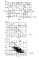
- the speed D of a pump is used as an operating parameter for performing the method according to the invention.
- a target speed of 80% of the maximum speed (upper limit value) of a pump is set as the control target R. This means that in a prescribed system of a plurality of heat exchangers, which are assigned to each decentralized pumps, that pump with the maximum speed should not permanently exceed or fall below the predetermined setpoint speed of 80% of the maximum speed.
- the associated temperature drop in the unit of use is determined by the decentralized pump of the considered heat exchanger / radiator, so that to cover the increased heat demand, the pump automatically due to their central or decentralized control the speed of the target speed 80%, in this example up to 100 %, ie up to the maximum speed increased by one Heating the cooled use unit, such as a living room to ensure.
- the pump will then automatically reduce the speed D due to their self-sufficient temperature-controlled speed control, which here in the illustration of FIG 1 initially an excess control to speeds D below the target value of 80% is achieved and in the course of the looped control method, the flow temperature VT settles in such a way by controlling the power of the boiler, that the control target of 80% of the maximum speed is achieved even in the considered here pump.
- the curve of the flow temperature VT e.g. a middle value.
- the flow temperature in an intermittent boiler operation can fluctuate around these respective average values.
- the gray shaded control range RB below the heating curve H shown in Figure 2 represents the possible range in which the flow temperature VT raised 1 (whereby the speed D falls) or lowered 2 (whereby the speed D increases) can be, so as to approximate the desired speed of the pump to the control target.
- the controlled variable is the speed of the respectively "least favorable" pump (for example 80% of the maximum speed) and the manipulated variable the flow temperature reduction (difference between heating curve and setpoint).
- the maximum flow temperature VTH according to the heating curve can be seen as the upper constant straight line at about 62 degrees Celsius. This preset according to the heating curve flow temperature VTH is never exceeded by the system.
- FIG. 3 shows, in a concrete representation, the possible control range below the heating curve H, the optimum flow temperatures VT obtained in order to achieve the respective control target of 80% of the maximum speed for the pump at each outside temperature T, which is the closest at the maximum speed.
Landscapes
- Engineering & Computer Science (AREA)
- Chemical & Material Sciences (AREA)
- Combustion & Propulsion (AREA)
- Mechanical Engineering (AREA)
- General Engineering & Computer Science (AREA)
- Physics & Mathematics (AREA)
- General Physics & Mathematics (AREA)
- Automation & Control Theory (AREA)
- Air Conditioning Control Device (AREA)
- Heating, Cooling, Or Curing Plastics Or The Like In General (AREA)
Applications Claiming Priority (1)
| Application Number | Priority Date | Filing Date | Title |
|---|---|---|---|
| DE102005037608A DE102005037608A1 (de) | 2005-08-05 | 2005-08-05 | Verfahren zur Regelung der Temperatur des Mediums eines Heiz- und/oder Kühlsystems |
Publications (3)
| Publication Number | Publication Date |
|---|---|
| EP1752852A2 true EP1752852A2 (fr) | 2007-02-14 |
| EP1752852A3 EP1752852A3 (fr) | 2012-05-23 |
| EP1752852B1 EP1752852B1 (fr) | 2014-06-25 |
Family
ID=37436226
Family Applications (1)
| Application Number | Title | Priority Date | Filing Date |
|---|---|---|---|
| EP06008356.5A Active EP1752852B1 (fr) | 2005-08-05 | 2006-04-22 | Procédé destiné au réglage de la température du caloporteur d'un système de chauffage et/ou de refroidissement |
Country Status (2)
| Country | Link |
|---|---|
| EP (1) | EP1752852B1 (fr) |
| DE (1) | DE102005037608A1 (fr) |
Cited By (9)
| Publication number | Priority date | Publication date | Assignee | Title |
|---|---|---|---|---|
| EP2663810A1 (fr) * | 2011-01-13 | 2013-11-20 | Ouman OY | Procédé, système de transfert de chaleur, système de réglage et produit-programme d'ordinateur pour commander un système de transfert de chaleur |
| DE102012018778A1 (de) * | 2012-09-24 | 2014-03-27 | Huu-Thoi Le | Verfahren zum Betrieb einer Heizungsanlage |
| DE202012012915U1 (de) | 2012-09-24 | 2014-07-17 | Huu-Thoi Le | Heiz- und/oder Kühlanlage |
| DE102016104666A1 (de) | 2016-03-14 | 2017-09-14 | Techem Energy Services Gmbh | Verfahren und Steuereinrichtung zur Erhöhung des Nutzungsgrads eines Wärmeerzeugers in einer Heizungsanlage |
| DE102016104667A1 (de) | 2016-03-14 | 2017-09-14 | Techem Energy Services Gmbh | Verfahren und Steuereinrichtung zur Erhöhung des Nutzungsgrads eines Wärmeerzeugers in einer Heizungsanlage |
| EP3757465A1 (fr) * | 2019-06-27 | 2020-12-30 | Wilo Se | Système et procédé de régulation d'un paramètre du milieu sur le côté secondaire d'un échangeur de chaleur |
| EP3757396A1 (fr) * | 2019-06-27 | 2020-12-30 | Wilo Se | Procédé et système de réglage d'un paramètre de milieu du milieux sur le côté secondaire d'un échangeur de chaleur |
| EP3779286A1 (fr) | 2019-08-12 | 2021-02-17 | Huu-Thoi Le | Procédé de fonctionnement d'une installation de chauffage |
| DE102019005722A1 (de) * | 2019-08-12 | 2021-02-18 | Huu-Thoi Le | Verfahren zum Betrieb einer Heizungsanlage |
Families Citing this family (3)
| Publication number | Priority date | Publication date | Assignee | Title |
|---|---|---|---|---|
| DE102013109134A1 (de) | 2013-08-23 | 2015-02-26 | Xylem Ip Holdings Llc | Verfahren zur Bestimmung einer Durchströmungsmenge an einem Flüssigkeitsfördersystem, Verfahren zur Bestimmung einer Energiemenge einer Förderflüssigkeit, Flüssigkeitsfördersystem und Pumpe |
| DE102014016791B4 (de) * | 2014-11-14 | 2022-05-12 | Paw Gmbh & Co. Kg | Verfahren zur hydraulischen Regelung mehrerer Heizkreisläufe am Verteilerbalken |
| CZ2015399A3 (cs) | 2015-06-15 | 2017-02-08 | Jiří Dostál | Zapojení systému pro řízení výkonu a diagnostiku tepelného výměníku |
Citations (1)
| Publication number | Priority date | Publication date | Assignee | Title |
|---|---|---|---|---|
| EP1003089B1 (fr) | 1998-11-18 | 2005-01-19 | Wilo Ag | Régulation en fonction de la demande pour un dispositif de transfert de chaleur |
Family Cites Families (5)
| Publication number | Priority date | Publication date | Assignee | Title |
|---|---|---|---|---|
| AU515910B2 (en) * | 1978-10-19 | 1981-05-07 | Matsushita Electric Industrial Co., Ltd. | Air conditioning system having a plurality of indoor units |
| DE3036661C2 (de) * | 1980-09-29 | 1984-08-02 | Siemens AG, 1000 Berlin und 8000 München | Zentrale Warmwasserheizungsanlage |
| DE3315828A1 (de) * | 1983-04-30 | 1984-10-31 | Licentia Patent-Verwaltungs-Gmbh, 6000 Frankfurt | Heizungsanlage |
| DE3643434A1 (de) * | 1986-12-19 | 1988-06-30 | Gentischer Josef Dipl Ing Fh | Anordnung zum steuern oder regeln einer warmwasser-heizungsanlage |
| DE19842174A1 (de) * | 1998-09-15 | 2000-03-16 | Wilo Gmbh | Pumpenregelung |
-
2005
- 2005-08-05 DE DE102005037608A patent/DE102005037608A1/de not_active Withdrawn
-
2006
- 2006-04-22 EP EP06008356.5A patent/EP1752852B1/fr active Active
Patent Citations (1)
| Publication number | Priority date | Publication date | Assignee | Title |
|---|---|---|---|---|
| EP1003089B1 (fr) | 1998-11-18 | 2005-01-19 | Wilo Ag | Régulation en fonction de la demande pour un dispositif de transfert de chaleur |
Cited By (14)
| Publication number | Priority date | Publication date | Assignee | Title |
|---|---|---|---|---|
| EP2663810A1 (fr) * | 2011-01-13 | 2013-11-20 | Ouman OY | Procédé, système de transfert de chaleur, système de réglage et produit-programme d'ordinateur pour commander un système de transfert de chaleur |
| EP2663810A4 (fr) * | 2011-01-13 | 2014-09-24 | Ouman Oy | Procédé, système de transfert de chaleur, système de réglage et produit-programme d'ordinateur pour commander un système de transfert de chaleur |
| DE102012018778A1 (de) * | 2012-09-24 | 2014-03-27 | Huu-Thoi Le | Verfahren zum Betrieb einer Heizungsanlage |
| DE202012012915U1 (de) | 2012-09-24 | 2014-07-17 | Huu-Thoi Le | Heiz- und/oder Kühlanlage |
| DE102014103668A1 (de) | 2012-09-24 | 2015-02-05 | Huu-Thoi Le | Verfahren zum Betrieb einer Heiz- und/oder Kühlanlage |
| DE102012018778B4 (de) * | 2012-09-24 | 2015-02-05 | Huu-Thoi Le | Verfahren zum Betrieb einer Heizungsanlage, Verfahren zum Betrieb einer Kühlanlage sowie Regeleinheit |
| DE102016104666A1 (de) | 2016-03-14 | 2017-09-14 | Techem Energy Services Gmbh | Verfahren und Steuereinrichtung zur Erhöhung des Nutzungsgrads eines Wärmeerzeugers in einer Heizungsanlage |
| DE102016104667A1 (de) | 2016-03-14 | 2017-09-14 | Techem Energy Services Gmbh | Verfahren und Steuereinrichtung zur Erhöhung des Nutzungsgrads eines Wärmeerzeugers in einer Heizungsanlage |
| EP3220066A1 (fr) | 2016-03-14 | 2017-09-20 | Techem Energy Services GmbH | Méthode et controleur pour augmenter le taux d'utilisation d'un générateur de chaleur dans un système de chauffage |
| EP3220065A1 (fr) | 2016-03-14 | 2017-09-20 | Techem Energy Services GmbH | Méthode et appareil de contrôle pour augmenter le taux de performance d'un générateur de chaleur dans une installation de chauffage |
| EP3757465A1 (fr) * | 2019-06-27 | 2020-12-30 | Wilo Se | Système et procédé de régulation d'un paramètre du milieu sur le côté secondaire d'un échangeur de chaleur |
| EP3757396A1 (fr) * | 2019-06-27 | 2020-12-30 | Wilo Se | Procédé et système de réglage d'un paramètre de milieu du milieux sur le côté secondaire d'un échangeur de chaleur |
| EP3779286A1 (fr) | 2019-08-12 | 2021-02-17 | Huu-Thoi Le | Procédé de fonctionnement d'une installation de chauffage |
| DE102019005722A1 (de) * | 2019-08-12 | 2021-02-18 | Huu-Thoi Le | Verfahren zum Betrieb einer Heizungsanlage |
Also Published As
| Publication number | Publication date |
|---|---|
| EP1752852B1 (fr) | 2014-06-25 |
| DE102005037608A1 (de) | 2007-02-08 |
| EP1752852A3 (fr) | 2012-05-23 |
Similar Documents
| Publication | Publication Date | Title |
|---|---|---|
| EP1752852B1 (fr) | Procédé destiné au réglage de la température du caloporteur d'un système de chauffage et/ou de refroidissement | |
| EP2580630B1 (fr) | Procédé de réglage du débit volumique d'un milieu chauffant et/ou réfrigérant au moyen d'échangeurs de chaleur ambiante d'une installation de chauffage ou de refroidissement | |
| DE10312825B4 (de) | Verfahren zum Einstellen mehrerer parallel geschalteter Wärmetauscher | |
| EP2960587B1 (fr) | Procédé de limitation du débit d'alimentation dans un système de transmission de chaleur | |
| EP3722680B1 (fr) | Procédé de réalisation d'une comparaison hydraulique d'un système de chauffage pour un bâtiment ainsi que système de chauffage conçu pour celui-ci | |
| EP3059652B1 (fr) | Dispositif de commande et installation de regulation de temperature ambiante | |
| DE2843929A1 (de) | Anordnung zur steuerung der raumtemperatur | |
| DE102006013098C5 (de) | Verfahren und Vorrichtung zur bedarfsgeführten Wärmebereitstellung in einer Heizungsanlage | |
| DE102014102275B4 (de) | Verfahren zur Regelung einer Heizungs- und/oder Klimaanlage und Heizungs- und/oder Klimaanlage hierzu | |
| EP3473939B1 (fr) | Procédé de fonctionnement d'une installation de chauffage et installation de chauffage | |
| DE4312150C2 (de) | Verfahren zum Einstellen der Förderleistung einer Umwälzpumpe | |
| EP3924670A1 (fr) | Procédé pour réguler une pompe de circulation | |
| WO2003023288A1 (fr) | Installation de chauffage central | |
| EP1003089B2 (fr) | Régulation en fonction de la demande pour un dispositif de transfert de chaleur | |
| EP0192225A2 (fr) | Procédé et dispositif de régulation de température de locaux | |
| WO2009140986A1 (fr) | Régulation de ligne de systèmes de chauffage réalisée selon les besoins | |
| DE202020106754U1 (de) | Gebäude mit mehreren beheizbaren Räumen | |
| DE10114822A1 (de) | Verfahren und Vorrichtung zum Regeln oder Steuern der Energiezufuhr zu Heizkörpern in einem Heizsystem und Verwendung einer Pumpe zu diesem Zweck | |
| DE3505600A1 (de) | Verfahren und vorrichtung zur regelung der temperatur in zu temperierenden raeumen | |
| DE102012101850A1 (de) | Verfahren zur bedarfsgeführten Regelung eines Wärmeerzeugers in einer Heizungsanlage | |
| EP1934666A1 (fr) | Procede de commande et/ou de regulation d'une temperature ambiante dans un batiment | |
| EP3350515B1 (fr) | Procédé et dispositif de régulation de la température d'un milieu porteur fluide | |
| EP2937636A1 (fr) | Système de ballon tampon destiné à être utilisé dans un réseau de chauffage local ou distant | |
| EP2339249A1 (fr) | Procédé de commande d'un système de thermorégulation pour un bâtiment | |
| DE3505601A1 (de) | Verfahren und vorrichtung zur regelung der temperatur in zu temperierenden raeumen |
Legal Events
| Date | Code | Title | Description |
|---|---|---|---|
| PUAI | Public reference made under article 153(3) epc to a published international application that has entered the european phase |
Free format text: ORIGINAL CODE: 0009012 |
|
| AK | Designated contracting states |
Kind code of ref document: A2 Designated state(s): AT BE BG CH CY CZ DE DK EE ES FI FR GB GR HU IE IS IT LI LT LU LV MC NL PL PT RO SE SI SK TR |
|
| AX | Request for extension of the european patent |
Extension state: AL BA HR MK YU |
|
| PUAL | Search report despatched |
Free format text: ORIGINAL CODE: 0009013 |
|
| AK | Designated contracting states |
Kind code of ref document: A3 Designated state(s): AT BE BG CH CY CZ DE DK EE ES FI FR GB GR HU IE IS IT LI LT LU LV MC NL PL PT RO SE SI SK TR |
|
| AX | Request for extension of the european patent |
Extension state: AL BA HR MK YU |
|
| RIC1 | Information provided on ipc code assigned before grant |
Ipc: G05D 23/19 20060101AFI20120417BHEP Ipc: F24F 11/06 20060101ALI20120417BHEP |
|
| 17P | Request for examination filed |
Effective date: 20120612 |
|
| AKX | Designation fees paid |
Designated state(s): AT BE BG CH CY CZ DE DK EE ES FI FR GB GR HU IE IS IT LI LT LU LV MC NL PL PT RO SE SI SK TR |
|
| GRAP | Despatch of communication of intention to grant a patent |
Free format text: ORIGINAL CODE: EPIDOSNIGR1 |
|
| RIC1 | Information provided on ipc code assigned before grant |
Ipc: F24F 11/06 20060101ALI20131118BHEP Ipc: G05D 23/19 20060101AFI20131118BHEP |
|
| INTG | Intention to grant announced |
Effective date: 20131211 |
|
| RAP1 | Party data changed (applicant data changed or rights of an application transferred) |
Owner name: WILO SE |
|
| GRAS | Grant fee paid |
Free format text: ORIGINAL CODE: EPIDOSNIGR3 |
|
| GRAA | (expected) grant |
Free format text: ORIGINAL CODE: 0009210 |
|
| AK | Designated contracting states |
Kind code of ref document: B1 Designated state(s): AT BE BG CH CY CZ DE DK EE ES FI FR GB GR HU IE IS IT LI LT LU LV MC NL PL PT RO SE SI SK TR |
|
| REG | Reference to a national code |
Ref country code: GB Ref legal event code: FG4D Free format text: NOT ENGLISH |
|
| REG | Reference to a national code |
Ref country code: CH Ref legal event code: EP |
|
| REG | Reference to a national code |
Ref country code: AT Ref legal event code: REF Ref document number: 675052 Country of ref document: AT Kind code of ref document: T Effective date: 20140715 |
|
| REG | Reference to a national code |
Ref country code: IE Ref legal event code: FG4D Free format text: LANGUAGE OF EP DOCUMENT: GERMAN |
|
| REG | Reference to a national code |
Ref country code: DE Ref legal event code: R096 Ref document number: 502006013815 Country of ref document: DE Effective date: 20140731 |
|
| PG25 | Lapsed in a contracting state [announced via postgrant information from national office to epo] |
Ref country code: GR Free format text: LAPSE BECAUSE OF FAILURE TO SUBMIT A TRANSLATION OF THE DESCRIPTION OR TO PAY THE FEE WITHIN THE PRESCRIBED TIME-LIMIT Effective date: 20140926 Ref country code: LT Free format text: LAPSE BECAUSE OF FAILURE TO SUBMIT A TRANSLATION OF THE DESCRIPTION OR TO PAY THE FEE WITHIN THE PRESCRIBED TIME-LIMIT Effective date: 20140625 Ref country code: FI Free format text: LAPSE BECAUSE OF FAILURE TO SUBMIT A TRANSLATION OF THE DESCRIPTION OR TO PAY THE FEE WITHIN THE PRESCRIBED TIME-LIMIT Effective date: 20140625 Ref country code: CY Free format text: LAPSE BECAUSE OF FAILURE TO SUBMIT A TRANSLATION OF THE DESCRIPTION OR TO PAY THE FEE WITHIN THE PRESCRIBED TIME-LIMIT Effective date: 20140625 |
|
| REG | Reference to a national code |
Ref country code: NL Ref legal event code: VDEP Effective date: 20140625 |
|
| REG | Reference to a national code |
Ref country code: LT Ref legal event code: MG4D |
|
| PG25 | Lapsed in a contracting state [announced via postgrant information from national office to epo] |
Ref country code: SE Free format text: LAPSE BECAUSE OF FAILURE TO SUBMIT A TRANSLATION OF THE DESCRIPTION OR TO PAY THE FEE WITHIN THE PRESCRIBED TIME-LIMIT Effective date: 20140625 Ref country code: LV Free format text: LAPSE BECAUSE OF FAILURE TO SUBMIT A TRANSLATION OF THE DESCRIPTION OR TO PAY THE FEE WITHIN THE PRESCRIBED TIME-LIMIT Effective date: 20140625 |
|
| PG25 | Lapsed in a contracting state [announced via postgrant information from national office to epo] |
Ref country code: ES Free format text: LAPSE BECAUSE OF FAILURE TO SUBMIT A TRANSLATION OF THE DESCRIPTION OR TO PAY THE FEE WITHIN THE PRESCRIBED TIME-LIMIT Effective date: 20140625 Ref country code: SK Free format text: LAPSE BECAUSE OF FAILURE TO SUBMIT A TRANSLATION OF THE DESCRIPTION OR TO PAY THE FEE WITHIN THE PRESCRIBED TIME-LIMIT Effective date: 20140625 Ref country code: RO Free format text: LAPSE BECAUSE OF FAILURE TO SUBMIT A TRANSLATION OF THE DESCRIPTION OR TO PAY THE FEE WITHIN THE PRESCRIBED TIME-LIMIT Effective date: 20140625 Ref country code: CZ Free format text: LAPSE BECAUSE OF FAILURE TO SUBMIT A TRANSLATION OF THE DESCRIPTION OR TO PAY THE FEE WITHIN THE PRESCRIBED TIME-LIMIT Effective date: 20140625 Ref country code: PT Free format text: LAPSE BECAUSE OF FAILURE TO SUBMIT A TRANSLATION OF THE DESCRIPTION OR TO PAY THE FEE WITHIN THE PRESCRIBED TIME-LIMIT Effective date: 20141027 Ref country code: EE Free format text: LAPSE BECAUSE OF FAILURE TO SUBMIT A TRANSLATION OF THE DESCRIPTION OR TO PAY THE FEE WITHIN THE PRESCRIBED TIME-LIMIT Effective date: 20140625 |
|
| PG25 | Lapsed in a contracting state [announced via postgrant information from national office to epo] |
Ref country code: IS Free format text: LAPSE BECAUSE OF FAILURE TO SUBMIT A TRANSLATION OF THE DESCRIPTION OR TO PAY THE FEE WITHIN THE PRESCRIBED TIME-LIMIT Effective date: 20141025 Ref country code: NL Free format text: LAPSE BECAUSE OF FAILURE TO SUBMIT A TRANSLATION OF THE DESCRIPTION OR TO PAY THE FEE WITHIN THE PRESCRIBED TIME-LIMIT Effective date: 20140625 Ref country code: PL Free format text: LAPSE BECAUSE OF FAILURE TO SUBMIT A TRANSLATION OF THE DESCRIPTION OR TO PAY THE FEE WITHIN THE PRESCRIBED TIME-LIMIT Effective date: 20140625 |
|
| REG | Reference to a national code |
Ref country code: DE Ref legal event code: R097 Ref document number: 502006013815 Country of ref document: DE |
|
| PG25 | Lapsed in a contracting state [announced via postgrant information from national office to epo] |
Ref country code: DK Free format text: LAPSE BECAUSE OF FAILURE TO SUBMIT A TRANSLATION OF THE DESCRIPTION OR TO PAY THE FEE WITHIN THE PRESCRIBED TIME-LIMIT Effective date: 20140625 |
|
| PLBE | No opposition filed within time limit |
Free format text: ORIGINAL CODE: 0009261 |
|
| STAA | Information on the status of an ep patent application or granted ep patent |
Free format text: STATUS: NO OPPOSITION FILED WITHIN TIME LIMIT |
|
| 26N | No opposition filed |
Effective date: 20150326 |
|
| PG25 | Lapsed in a contracting state [announced via postgrant information from national office to epo] |
Ref country code: SI Free format text: LAPSE BECAUSE OF FAILURE TO SUBMIT A TRANSLATION OF THE DESCRIPTION OR TO PAY THE FEE WITHIN THE PRESCRIBED TIME-LIMIT Effective date: 20140625 Ref country code: MC Free format text: LAPSE BECAUSE OF FAILURE TO SUBMIT A TRANSLATION OF THE DESCRIPTION OR TO PAY THE FEE WITHIN THE PRESCRIBED TIME-LIMIT Effective date: 20140625 Ref country code: LU Free format text: LAPSE BECAUSE OF FAILURE TO SUBMIT A TRANSLATION OF THE DESCRIPTION OR TO PAY THE FEE WITHIN THE PRESCRIBED TIME-LIMIT Effective date: 20150422 |
|
| REG | Reference to a national code |
Ref country code: CH Ref legal event code: PL |
|
| GBPC | Gb: european patent ceased through non-payment of renewal fee |
Effective date: 20150422 |
|
| REG | Reference to a national code |
Ref country code: IE Ref legal event code: MM4A |
|
| PG25 | Lapsed in a contracting state [announced via postgrant information from national office to epo] |
Ref country code: LI Free format text: LAPSE BECAUSE OF NON-PAYMENT OF DUE FEES Effective date: 20150430 Ref country code: CH Free format text: LAPSE BECAUSE OF NON-PAYMENT OF DUE FEES Effective date: 20150430 Ref country code: GB Free format text: LAPSE BECAUSE OF NON-PAYMENT OF DUE FEES Effective date: 20150422 |
|
| REG | Reference to a national code |
Ref country code: FR Ref legal event code: PLFP Year of fee payment: 11 |
|
| PG25 | Lapsed in a contracting state [announced via postgrant information from national office to epo] |
Ref country code: IE Free format text: LAPSE BECAUSE OF NON-PAYMENT OF DUE FEES Effective date: 20150422 |
|
| REG | Reference to a national code |
Ref country code: AT Ref legal event code: MM01 Ref document number: 675052 Country of ref document: AT Kind code of ref document: T Effective date: 20150422 |
|
| PG25 | Lapsed in a contracting state [announced via postgrant information from national office to epo] |
Ref country code: AT Free format text: LAPSE BECAUSE OF NON-PAYMENT OF DUE FEES Effective date: 20150422 |
|
| REG | Reference to a national code |
Ref country code: FR Ref legal event code: PLFP Year of fee payment: 12 |
|
| PG25 | Lapsed in a contracting state [announced via postgrant information from national office to epo] |
Ref country code: BG Free format text: LAPSE BECAUSE OF FAILURE TO SUBMIT A TRANSLATION OF THE DESCRIPTION OR TO PAY THE FEE WITHIN THE PRESCRIBED TIME-LIMIT Effective date: 20140625 Ref country code: HU Free format text: LAPSE BECAUSE OF FAILURE TO SUBMIT A TRANSLATION OF THE DESCRIPTION OR TO PAY THE FEE WITHIN THE PRESCRIBED TIME-LIMIT; INVALID AB INITIO Effective date: 20060422 |
|
| PG25 | Lapsed in a contracting state [announced via postgrant information from national office to epo] |
Ref country code: BE Free format text: LAPSE BECAUSE OF NON-PAYMENT OF DUE FEES Effective date: 20150430 |
|
| PG25 | Lapsed in a contracting state [announced via postgrant information from national office to epo] |
Ref country code: TR Free format text: LAPSE BECAUSE OF FAILURE TO SUBMIT A TRANSLATION OF THE DESCRIPTION OR TO PAY THE FEE WITHIN THE PRESCRIBED TIME-LIMIT Effective date: 20140625 |
|
| REG | Reference to a national code |
Ref country code: FR Ref legal event code: PLFP Year of fee payment: 13 |
|
| PGFP | Annual fee paid to national office [announced via postgrant information from national office to epo] |
Ref country code: IT Payment date: 20210323 Year of fee payment: 16 |
|
| PGFP | Annual fee paid to national office [announced via postgrant information from national office to epo] |
Ref country code: FR Payment date: 20220323 Year of fee payment: 17 |
|
| PG25 | Lapsed in a contracting state [announced via postgrant information from national office to epo] |
Ref country code: IT Free format text: LAPSE BECAUSE OF NON-PAYMENT OF DUE FEES Effective date: 20220422 |
|
| P01 | Opt-out of the competence of the unified patent court (upc) registered |
Effective date: 20230615 |
|
| PGFP | Annual fee paid to national office [announced via postgrant information from national office to epo] |
Ref country code: DE Payment date: 20230321 Year of fee payment: 18 |
|
| PG25 | Lapsed in a contracting state [announced via postgrant information from national office to epo] |
Ref country code: FR Free format text: LAPSE BECAUSE OF NON-PAYMENT OF DUE FEES Effective date: 20230430 |
|
| REG | Reference to a national code |
Ref country code: DE Ref legal event code: R084 Ref document number: 502006013815 Country of ref document: DE |