EP1752838A1 - Optical wavefront control pattern generating apparatus and optical wavefront control pattern generating method - Google Patents
Optical wavefront control pattern generating apparatus and optical wavefront control pattern generating method Download PDFInfo
- Publication number
- EP1752838A1 EP1752838A1 EP05737037A EP05737037A EP1752838A1 EP 1752838 A1 EP1752838 A1 EP 1752838A1 EP 05737037 A EP05737037 A EP 05737037A EP 05737037 A EP05737037 A EP 05737037A EP 1752838 A1 EP1752838 A1 EP 1752838A1
- Authority
- EP
- European Patent Office
- Prior art keywords
- optical wavefront
- control pattern
- reconstructed image
- wavefront control
- unit
- Prior art date
- Legal status (The legal status is an assumption and is not a legal conclusion. Google has not performed a legal analysis and makes no representation as to the accuracy of the status listed.)
- Withdrawn
Links
Images


Classifications
-
- G—PHYSICS
- G03—PHOTOGRAPHY; CINEMATOGRAPHY; ANALOGOUS TECHNIQUES USING WAVES OTHER THAN OPTICAL WAVES; ELECTROGRAPHY; HOLOGRAPHY
- G03H—HOLOGRAPHIC PROCESSES OR APPARATUS
- G03H1/00—Holographic processes or apparatus using light, infrared or ultraviolet waves for obtaining holograms or for obtaining an image from them; Details peculiar thereto
- G03H1/04—Processes or apparatus for producing holograms
- G03H1/08—Synthesising holograms, i.e. holograms synthesized from objects or objects from holograms
- G03H1/0808—Methods of numerical synthesis, e.g. coherent ray tracing [CRT], diffraction specific
-
- G—PHYSICS
- G03—PHOTOGRAPHY; CINEMATOGRAPHY; ANALOGOUS TECHNIQUES USING WAVES OTHER THAN OPTICAL WAVES; ELECTROGRAPHY; HOLOGRAPHY
- G03H—HOLOGRAPHIC PROCESSES OR APPARATUS
- G03H1/00—Holographic processes or apparatus using light, infrared or ultraviolet waves for obtaining holograms or for obtaining an image from them; Details peculiar thereto
- G03H1/04—Processes or apparatus for producing holograms
-
- G—PHYSICS
- G03—PHOTOGRAPHY; CINEMATOGRAPHY; ANALOGOUS TECHNIQUES USING WAVES OTHER THAN OPTICAL WAVES; ELECTROGRAPHY; HOLOGRAPHY
- G03H—HOLOGRAPHIC PROCESSES OR APPARATUS
- G03H1/00—Holographic processes or apparatus using light, infrared or ultraviolet waves for obtaining holograms or for obtaining an image from them; Details peculiar thereto
-
- G—PHYSICS
- G03—PHOTOGRAPHY; CINEMATOGRAPHY; ANALOGOUS TECHNIQUES USING WAVES OTHER THAN OPTICAL WAVES; ELECTROGRAPHY; HOLOGRAPHY
- G03H—HOLOGRAPHIC PROCESSES OR APPARATUS
- G03H1/00—Holographic processes or apparatus using light, infrared or ultraviolet waves for obtaining holograms or for obtaining an image from them; Details peculiar thereto
- G03H1/04—Processes or apparatus for producing holograms
- G03H1/0486—Improving or monitoring the quality of the record, e.g. by compensating distortions, aberrations
-
- G—PHYSICS
- G03—PHOTOGRAPHY; CINEMATOGRAPHY; ANALOGOUS TECHNIQUES USING WAVES OTHER THAN OPTICAL WAVES; ELECTROGRAPHY; HOLOGRAPHY
- G03H—HOLOGRAPHIC PROCESSES OR APPARATUS
- G03H1/00—Holographic processes or apparatus using light, infrared or ultraviolet waves for obtaining holograms or for obtaining an image from them; Details peculiar thereto
- G03H1/22—Processes or apparatus for obtaining an optical image from holograms
-
- G—PHYSICS
- G03—PHOTOGRAPHY; CINEMATOGRAPHY; ANALOGOUS TECHNIQUES USING WAVES OTHER THAN OPTICAL WAVES; ELECTROGRAPHY; HOLOGRAPHY
- G03H—HOLOGRAPHIC PROCESSES OR APPARATUS
- G03H1/00—Holographic processes or apparatus using light, infrared or ultraviolet waves for obtaining holograms or for obtaining an image from them; Details peculiar thereto
- G03H1/22—Processes or apparatus for obtaining an optical image from holograms
- G03H1/2294—Addressing the hologram to an active spatial light modulator
-
- G—PHYSICS
- G03—PHOTOGRAPHY; CINEMATOGRAPHY; ANALOGOUS TECHNIQUES USING WAVES OTHER THAN OPTICAL WAVES; ELECTROGRAPHY; HOLOGRAPHY
- G03H—HOLOGRAPHIC PROCESSES OR APPARATUS
- G03H1/00—Holographic processes or apparatus using light, infrared or ultraviolet waves for obtaining holograms or for obtaining an image from them; Details peculiar thereto
- G03H1/04—Processes or apparatus for producing holograms
- G03H1/0486—Improving or monitoring the quality of the record, e.g. by compensating distortions, aberrations
- G03H2001/0491—Improving or monitoring the quality of the record, e.g. by compensating distortions, aberrations by monitoring the hologram formation, e.g. via a feed-back loop
-
- G—PHYSICS
- G03—PHOTOGRAPHY; CINEMATOGRAPHY; ANALOGOUS TECHNIQUES USING WAVES OTHER THAN OPTICAL WAVES; ELECTROGRAPHY; HOLOGRAPHY
- G03H—HOLOGRAPHIC PROCESSES OR APPARATUS
- G03H1/00—Holographic processes or apparatus using light, infrared or ultraviolet waves for obtaining holograms or for obtaining an image from them; Details peculiar thereto
- G03H1/22—Processes or apparatus for obtaining an optical image from holograms
- G03H1/2202—Reconstruction geometries or arrangements
- G03H2001/2244—Means for detecting or recording the holobject
Definitions
- the present invention relates to an optical wavefront control pattern generating apparatus and an optical wavefront control pattern generating method which generate an optimum optical wavefront control pattern which is to be stored in an optical wavefront controller unit, in an image reconstruction system displaying a reconstructed image on a reconstructed image display unit, by irradiating the optical wavefront controller unit, in which an optical wavefront control pattern is recorded, with illuminating light.
- holography has been known as a technology for displaying a reconstructed image on a reconstructed image display unit, by irradiating an optical wavefront controller unit, in which an optical wavefront control pattern (a hologram) is recorded, with illuminating light.
- the "holography” is a technology for reconstructing an optical wavefront itself of an object beam, by controlling at least any one of a phase and an amplitude of the illuminating light by using the optical wavefront control pattern stored in the optical wavefront controller unit.
- a "simulated annealing" method has been conventionally known as an approximate solution method used for solving a combination optimization problem.
- the "simulated annealing" method is a stochastic search technique in which a solution space is searched, and in which an optimum solution is obtained, by repeating an operation (a Move operation) of modifying one solution to another.
- the temperature parameter value T is caused to gradually decrease through an algorithm of the "simulated annealing” method from a sufficiently high temperature to a sufficiently low temperature by taking a sufficiently long time period.
- CGHs computer generated holograms
- holograms optical wavefront control patterns
- the amount of computation which is “O (NlogN)” means an amount of computation which is in the order of NlogN
- the amount of computation which is "O(N)” means an amount of computation which is in the order of N.
- the premise is that an amplitude of light on a hologram surface is constant.
- An object of the present invention is to provide an optical wavefront control pattern generating apparatus and an optical wavefront control pattern generating method with which the problem with noise, which is practically insoluble with software, can be solved through processing with hardware, and with which a desired reconstructed image can be obtained faster and more accurately.
- a first aspect of the present invention is summarized as an optical wavefront control pattern generating apparatus which generates an optimum optical wavefront control pattern which is to be stored in an optical wavefront controller unit, in an image reconstruction system displaying a reconstructed image on a reconstructed image display unit, by irradiating the optical wavefront controller unit, in which an optical wavefront control pattern is recorded, with illuminating light
- the apparatus includes: a reconstructed image detector unit configured to detect a reconstructed image displayed on the reconstructed image display unit; and an optimizer unit configured to evaluate the reconstructed image detected by the reconstructed image detector unit, and to generate the optimum optical wavefront control pattern by applying a modification process to the optical wavefront control pattern in order for a result of the evaluation to satisfy a predetermined condition.
- the optimizer unit can be configured to generate the optimum optical wavefront control pattern, by repeating an application of a modification process to the optical wavefront control pattern, a computation of an evaluation value of a reconstructed image corresponding to the optical wavefront control pattern to which the modification process has been applied, and a determination, on the basis of the evaluation value, of whether or not the optical wavefront control pattern, to which the modification process has been applied, is to be adopted.
- the optimizer unit on the basis of difference information on evaluation values of the reconstructed image respectively before and after the modification process, can be configured to determine whether or not the optical wavefront control pattern, to which the modification process has been applied, is to be adopted.
- the optimizer unit on the basis of the difference information and of an adoption probability determined by a repetitive parameter value, can be configured to determine whether or not the optical wavefront control pattern, to which the modification process has been applied, is to be adopted.
- the optimizer unit can be configured to repeat the application of the modification process, the computation of the evaluation value, and the determination, until the evaluation values of the reconstructed image converge on a predetermined repetitive parameter value.
- the optimizer unit can be configured to vary the predetermined repetitive parameter value within a predetermined range.
- the optical wavefront controller unit can include an optical wavefront control device capable of modulating at least any one of an amplitude and a phase of the illuminating light by use of the recorded optical wavefront control pattern.
- the reconstructed image detector unit can include a sensor capable of detecting the reconstructed image displayed on the reconstructed image display unit by use of reconstruction light obtained by modulating at least any one of an amplitude and a phase of the illuminating light.
- the optimizer unit can be configured to evaluate the reconstructed image on the basis of the reconstructed image detected by the sensor.
- the reconstructed image detector unit can include a plurality of sensors each capable of detecting the reconstructed image displayed on the reconstructed image display unit by use of reconstruction light obtained by modulating at least any one of an amplitude and a phase of the illuminating light, and the optimizer unit can be configured to evaluate the reconstructed image on the bases of a plurality of reconstructed images respectively detected by the plurality of sensors.
- a first aspect of the present invention is summarized as an optical wavefront control pattern generating method for generating an optimum optical wavefront control pattern which is to be stored in an optical wavefront controller unit, in an image reconstruction system displaying a reconstructed image on a reconstructed image display unit, by irradiating the optical wavefront controller unit, in which an optical wavefront control pattern is recorded, with illuminating light, the method includes the steps of: detecting a reconstructed image displayed on the reconstructed image display unit; evaluating the reconstructed image detected by a reconstructed image display unit; and generating the optimum optical wavefront control pattern by applying a modification process to the optical wavefront control pattern in order for a result of the evaluation to satisfy a predetermined condition.
- an optical wavefront control pattern generating apparatus 1 By irradiating an optical wavefront controller unit 20, in which the optimum optical wavefront control pattern is recorded, with illuminating light 2, the optical wavefront control pattern generating apparatus 1 according to this embodiment is configured to generate the optimum optical wavefront control pattern, which is to be stored in the optical wavefront controller unit 20, in an image reconstruction system A for displaying a reconstructed image on a reconstructed image display unit 30.
- the optical wavefront control pattern generating apparatus 1 includes an illuminating light irradiator unit 10, the optical wavefront controller unit 20, the reconstructed image display unit 30, a reconstructed image detector unit 40, and an optimizer unit 50.
- the illuminating light irradiator unit 10 is configured to irradiate an optical wavefront control pattern (a hologram), which is displayed on an optical wavefront control device of the optical wavefront controller unit 20, with illuminating light.
- an optical wavefront control pattern a hologram
- the optical wavefront controller unit 20 is configured to record an optical wavefront control pattern transmitted from the optimizer unit 50, and is configured to then display the optical wavefront control pattern on the optical wavefront control device.
- the reconstructed image display unit 30 is configured to display the reconstructed image based on reconstruction light 3 propagated from the optical wavefront controller unit 20.
- the image reconstruction system A in the optical wavefront control pattern generating apparatus 1 at least any one of an amplitude and a phase of the illuminating light 2 irradiated from the illuminating light irradiator unit 10 is modulated by each pixel of the optical wavefront control pattern displayed on the optical wavefront control device. Thereby, the illuminating light 2 is converted into the reconstruction light 3. The reconstruction light 3 reaches the reconstructed image display unit 30 while changing traveling directions thereof, and thus the reconstructed image is displayed.
- the reconstructed image detector unit 40 is configured to detect the reconstructed image displayed on the reconstructed image display unit 30.
- the reconstructed image detector unit 40 includes a sensor which makes it possible to detect the reconstructed image displayed on the reconstructed image display unit 30 with the reconstruction light 3.
- the reconstruction light 3 is obtained by modulating at least any one of the amplitude and the phase of the illuminating light 2.
- the reconstructed image detector unit 40 photographs the reconstructed image displayed on the reconstructed image display unit 30 by use of the CCD camera, and transmits, to the optimizer unit 50, reconstructed image data obtained by digitizing the photographed reconstructed image.
- the optimizer unit 50 is configured to evaluate the reconstructed image detected by the reconstructed image detector unit 40, and to generate the optimum optical wavefront control pattern by applying a modification process to an optical wavefront control pattern in order for a result of the evaluation to satisfy a predetermined condition.
- the optimizer unit 50 is configured to evaluate, on the basis of the reconstructed image data obtained by digitizing the reconstructed image detected by the above-described sensor, the reconstructed image displayed on the reconstructed image display unit 30.
- the optimizer unit 50 may be configured to generate the optimum optical wavefront control pattern by using a "simulated annealing" method.
- the optimizer unit 50 may be configured to generate the optimum optical wavefront control pattern by repeating an application of a modification process (a Move operation) to an optical wavefront control pattern (a solution prior to the Move operation), a computation of an evaluation value E of a reconstructed image corresponding to an optical wavefront control pattern (a solution obtained after the Move operation) to which the modification process has been applied, and a determination, on the basis of the computed evaluation value E, of whether or not the optical wavefront control pattern (the solution obtained after the Move operation), to which the modification process (the Move operation) has been applied, is to be adopted.
- a modification process a Move operation
- the optimizer unit 50 may be configured to determine, on the basis of difference information ⁇ E on evaluation values E for the reconstructed image respectively before and after a modification process (a Move operation), whether or not an optical wavefront control pattern (a solution obtained after the Move operation), to which the modification process (the Move operation) has been applied, is to be adopted.
- the optimizer unit 50 may be configured to determine, on the basis of an adoption probability P defined by the difference information ⁇ E and a repetitive parameter value (a temperature parameter value T), whether or not the optical wavefront control pattern (the solution after the Move operation), to which the modification process (the Move operation) has been applied, is to be adopted.
- the optimizer unit 50 may be configured to repeat the modification process (the Move operation), computation of the evaluation value E, and the above-described determination until the evaluation values E of the reconstructed image converge on a predetermined repetitive parameter value (a temperature parameter value T).
- the optimizer unit 50 may be configured to vary the above-described repetitive parameter value (the temperature parameter value T) within a predetermined range (a range from a sufficiently high temperature to a sufficiently low temperature).
- the optimizer unit 50 may be configured to repeat the modification process (the Move operation), the computation of the evaluation value E, and the above-described determination until the evaluation values E of the reconstructed image converge on each of the repetitive parameter values (the temperature parameter values T) in the predetermined range.
- the optimizer unit 50 includes an initial optical wavefront control pattern generator unit 51, a reconstructed image data obtaining unit 52, an evaluation value computation unit 53, an evaluation unit 54, an optimum optical wavefront control pattern storage unit 55, an optical wavefront control pattern modification unit 56, and an output unit 57.
- an initial optical wavefront control pattern generator unit 51 a reconstructed image data obtaining unit 52
- an evaluation value computation unit 53 a reconstructed image data obtaining unit 52
- an evaluation unit 54 a optimum optical wavefront control pattern storage unit 55
- an optical wavefront control pattern modification unit 56 and an output unit 57.
- the optimizer unit 50 of the optical wavefront control pattern generating apparatus generates the optimum optical wavefront control pattern (a hologram) to be displayed on the optical wavefront control device of the optical wavefront controller unit 20, in order that a reconstructed image can be displayed on the reconstructed image display unit 30.
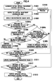
- step S1001 the initial optical wavefront control pattern generator unit 51 of the optimizer unit 50 generates an initial optical wavefront control pattern (an initial solution of the optical wavefront control pattern) A 0 .
- the initial optical wavefront control pattern generator unit 51 generates the initial optical wavefront control pattern A 0 by assigning random values of 0 to 255 respectively to pixels of the grayscale image on the liquid crystal panel.
- step S1001 of the initial optical wavefront control pattern A 0 , when a number of the pixels is defined as "N”, an amount of computation is expressed as "O(N)" because it is necessary to define values respectively for all of the pixels.
- the initial optical wavefront control pattern A 0 need not be a random value.
- the reason is as follows. Nearly 100 % of the Move operations, which worsen solutions, are adopted in a high-temperature state (a state where the temperature parameter value T is large) at the time immediately after an experiment starts regardless of the magnitude of a value taken for the initial optical wavefront control pattern A 0 .
- a high-temperature state a state where the temperature parameter value T is large
- step S1002 the output unit 57 of the optimizer 50 outputs, to the optical wavefront controller unit 20, the initial optical wavefront control pattern A 0 generated by the initial optical wavefront control pattern generator unit 51.
- step S1002 the output unit 57 of the optimizer unit 50 outputs, to the optical wavefront controller unit 20, an initial optical wavefront control pattern A 1 modified by the optical wavefront control pattern modification unit 56.
- step S1003 the illuminating light 2 irradiated by the illuminating light irradiator unit 10 is modulated to be reconstruction light 2 by the optical wavefront control pattern (Ao or A 1 ) displayed on the optical wavefront control device of the optical wavefront controller unit 20. Then, the reconstructed image display unit 30 displays the reconstructed image based on the reconstruction light 2.
- the reconstructed image detector unit 40 photographs the reconstructed image displayed on the reconstructed image display unit 30, and digitizes the photographed reconstructed image.
- the reconstructed image data obtaining unit 52 of the optimizer unit 50 obtains the digitized reconstructed image data from the reconstructed image detector unit 40.
- step S1004a the evaluation value computation unit 53 of the optimizer unit 50 compares the obtained reconstructed image data with target image data obtained by digitizing a target image previously inputted, and computes the evaluation value E (an evaluation value E 0 of the reconstructed image corresponding to the initial optical wavefront control pattern A 0 ) indicating how close the reconstructed image displayed on the reconstructed image display unit 30 is to the target image.
- the evaluation value computation unit 53 may be configured to compute the evaluation value E of the reconstructed image by taking an absolute value of a difference between a light intensity of the target image at each of coordinate points and a light intensity of the reconstructed image at each of the coordinate points, and thus by adding up the absolute values respectively for all of the coordinate points.
- the evaluation value computation unit 53 may be configured to compute the evaluation value E of the reconstructed image by taking an absolute value of a difference between a light intensity of the target image at each of coordinate points and a light intensity of the reconstructed image at each of the coordinate points, and thus by adding up the absolute values respectively for all of the coordinate points.
- the target image data it is possible to adopt data on an actual photographed image in which the target image is photographed by using a conventional digital camera or the like. In this case, it is possible to generate an "actual photographed hologram" in which a photographed image can be reconstructed. Thereby, it is made possible to apply the present invention to a hologram camera.
- the evaluation unit 54 of the optimizer unit 50 determines, on the basis of the computed evaluation value E of the reconstructed image, whether or not an optical wavefront control pattern corresponding to the above reconstructed image is improved. In a case where it is determined that the optical wavefront control pattern is improved (in a case of "Yes" in step S1004a), the operation proceeds to step S1004b. In a case where it is determined that it is not improved (in a case of "No" in step S1004a), the operation proceeds to step S1006.
- step S1004b the evaluation unit 54 determines whether or not the optical wavefront control pattern A j is improved as compared to the optimum optical wavefront control pattern stored in the optimum optical wavefront control pattern storage unit 55. In a case where it is determined that the optical wavefront control pattern A j is improved (in a case of "Yes” in step S1004b), the operation proceeds to step S1005. In a case where it is determined that it is not improved (in a case of "No" in step S1004b), the operation proceeds to step S1009.
- step S1005 the evaluation unit 54 stores the above optical wavefront control pattern A j , as the optimum optical wavefront control pattern, in the optimum optical wavefront control pattern storage unit 55.
- step S1005 the evaluation unit 54 determines that the above optical wavefront control pattern A j is to be adopted as the optimum optical wavefront pattern in a range searched so far.
- the evaluation unit 54 stores the initial optical wavefront control pattern A 0 , as the optimum optical wavefront pattern, in the optimum optical wavefront control pattern storage unit 55 without making the above-described determination.
- step S1006 the evaluation unit 54 computes an adoption probability P by using equation (1).
- the adoption probability P indicates a probability of adopting a local modification process (the Move operation) by which the optical wavefront control pattern A j is computed.
- P exp - ⁇ E / T
- T denotes a temperature parameter value
- step S1007 on the basis of the computed adoption probability P, the evaluation unit 54 determines whether or not the local modification process, by which the optical wavefront control pattern A j is computed, is to be adopted.
- the evaluation unit 54 performs an operation in step S1009 in a case where it is determined that the above local modification process is to be adopted.
- the evaluation unit 54 performs an operation in step S1008 in a case where it is determined that the above local modification process is not to be adopted.
- an optical wavefront control pattern modification unit 46 converts the optical wavefront control pattern A j back to the optical wavefront control pattern A j-1 which is in a state prior to the above-described local modification process.
- step S1009 the evaluation unit 54 determines whether or not evaluation values E j of a reconstructed image corresponding to the optical wavefront control pattern A j converge on the current temperature parameter value T.
- the evaluation unit 54 determines whether or not a sufficient number of times of the local modification processes are previously performed. In addition, this determination is made with the same method as that used for a determination made with the conventional "simulated annealing" method.
- the evaluation unit 54 performs an operation in step S1101 in a case where it is determined that the evaluation values E j of the above reconstructed image converge.
- the evaluation unit 54 performs an operation in step S1010 in a case where it is determined that the evaluation values E j of the above reconstructed image do not converge.
- step S1011 the evaluation unit 54 updates the temperature parameter value T.
- step S1012 the evaluation unit 54 determines whether or not evaluation values E j of a reconstructed image corresponding to the optical wavefront control pattern A j converge on the temperature parameter value T.
- the evaluation unit 54 determines whether or not the temperature parameter value T has dropped to a sufficiently low value, i.e., whether or not a sufficient number of times of the local modification processes have been performed. In addition, this determination is made with the same method as that used for a determination made with the conventional "simulated annealing" method.
- step S1013 This operation proceeds to step S1013 in a case where it is determined that a sufficient number of times of the local modification processes have been performed.
- the operation proceeds to step S1010 in a case where it is determined that a sufficient number of times of the local modification processes have not been performed.
- the optical wavefront control pattern modification unit 46 of the optimizer unit 50 applies the local modification process to the above optical wavefront control pattern A j .
- the local modification process can be defined as a process in which a value for one pixel of the grayscale image on the above-described liquid crystal panel is modified into a random value between 0 and 255.
- step S1013 the output unit 57 of the optimizer unit 50 outputs, as the optimum optical wavefront control pattern, an optical wavefront control pattern stored in the optimum optical wavefront control pattern storage unit 55. (Validation of operating speed in optical wavefront control pattern generating apparatus according to this embodiment)
- an operating speed in the optical wavefront control pattern generating apparatus will be validated below. Specifically, the operating speed in the optical wavefront control pattern generating apparatus according to this embodiment and an operating speed in a conventional technology will be compared with each other.
- dimensions of a hologram is set to be 128 x 128.
- Non-patent Document 2 Adopted as the conventional technology was an example in which a technique, as shown in Non-patent Document 2, for optimizing a Fourier-converted kinoform by using a "simulated annealing" method on the basis of difference information on solutions respectively before and after a Move operation is implemented in a workstation having a 600 MHz dual CPU; and in which a fast Fourier conversion is used for evaluation of a solution.
- steps (A) and (B) which depend on a performance of hardware can each be performed 60 times or more per second.
- step (D) can be performed 60 times or more per second when the workstation having a 600 MHz dual CPU is used.
- Step (C) is an operation of computing a difference between each pixel of the reconstructed image data and each pixel of the target image data which is corresponds to each pixel of the reconstructed image data, and an operation of thereafter computing a total of all of the differences. For this reason, by making it possible to perform in parallel the computation with dedicated hardware by using an FPGA or the like, it is made possible to process this step at a higher speed than in a case of normally processing the step by a general computer. Accordingly, it is considered that 60 or more times of step (C) can be executed in every second.
- optical wavefront control pattern generating apparatus makes it possible to generate an optimum optical wavefront control pattern (a hologram) at a higher speed than in the conventional technology.
- an optimum wavefront control pattern is generated in the following manner.
- the reconstructed image detector unit 40 such as a CCD camera, detects a reconstructed image actually displayed on the reconstructed image display unit 30, and the optimizer unit 50 evaluates the detected reconstructed image.
- the optimum optical wavefront control pattern (the hologram) is generated by using a reconstructed image obtained in an actual image reconstruction system (the optical system) A.
- the optical system the optical system
- the optical wavefront control pattern generating apparatus it is made possible to replace costs for a "step of computing a reconstructed image from a predetermined hologram", which requires the longest computation time when the optimum optical wavefront control pattern (the hologram) is generated by using the "simulated annealing" method, with costs for elements concerning hardware, as to how fast an operation of using the reconstructed image detector unit 40, such as a CCD camera, can be performed to photograph a reconstructed image generated by actually modulating the illuminating light 2.
- the optical wavefront controller unit 20 is configured to modulate at least any one of an amplitude and a phase of illuminating light irradiated by the illuminating light irradiator unit 10.
- the reconstructed image display unit 30 is configured to display a reconstructed image based on reconstruction light 2 obtained by modulating at least any one of the amplitude and the phase of the illuminating light.
- the reconstructed image detector unit 40 includes a plurality of sensors (for example, CCD cameras) which make it possible to detect the reconstructed image displayed on the reconstructed image display unit 30.
- the reconstructed image detector unit 40 includes a left sensor, a central sensor and a right sensor.
- the reconstructed image detector unit 40 makes it possible to obtain a plurality of reconstructed images photographed respectively from various angles.
- the optimizer unit 50 is configured to evaluate, on the bases of the plurality of reconstructed images detected by the respective plurality of sensors, the reconstructed image displayed on the reconstructed image display unit 30.
- the optimizer unit 50 is configured to compute reconstructed image data in the form of a three-dimensional image, on the bases of three reconstructed images respectively photographed by the left sensor, the central sensor and the right sensor, and then to compute an optimum optical wavefront control pattern by comparing the computed reconstructed image data in the form of a three-dimensional image with target image data in the form of a three-dimensional image.
- the optimizer unit 50 may be configured to manage target image data obtained from a direction toward the left side of the target image, that from a direction toward the center thereof, and that from a direction toward the right side thereof, and to compute an optimum optical wavefront control pattern by comparing these target image data respectively with target data obtained by digitizing the three reconstructed images respectively photographed by the left sensor, the central sensor and the right sensor.
- the present invention makes it possible to provide an optical wavefront control pattern generating apparatus and an optical wavefront control pattern generating method with which the problem with noise, which is practically insoluble with software, can be solved through processing with hardware; and with which a desired reconstructed image can be obtained faster and more accurately.
Landscapes
- Physics & Mathematics (AREA)
- General Physics & Mathematics (AREA)
- Holo Graphy (AREA)
- Image Processing (AREA)
- Optical Modulation, Optical Deflection, Nonlinear Optics, Optical Demodulation, Optical Logic Elements (AREA)
Abstract
Description
- The present invention relates to an optical wavefront control pattern generating apparatus and an optical wavefront control pattern generating method which generate an optimum optical wavefront control pattern which is to be stored in an optical wavefront controller unit, in an image reconstruction system displaying a reconstructed image on a reconstructed image display unit, by irradiating the optical wavefront controller unit, in which an optical wavefront control pattern is recorded, with illuminating light.
- Conventionally, "holography" has been known as a technology for displaying a reconstructed image on a reconstructed image display unit, by irradiating an optical wavefront controller unit, in which an optical wavefront control pattern (a hologram) is recorded, with illuminating light.
- The "holography" is a technology for reconstructing an optical wavefront itself of an object beam, by controlling at least any one of a phase and an amplitude of the illuminating light by using the optical wavefront control pattern stored in the optical wavefront controller unit.
- Additionally, a "simulated annealing" method has been conventionally known as an approximate solution method used for solving a combination optimization problem.
- The "simulated annealing" method is a stochastic search technique in which a solution space is searched, and in which an optimum solution is obtained, by repeating an operation (a Move operation) of modifying one solution to another.
- In the "simulated annealing" method, in a case where an evaluation value E of a solution is enhanced (that is, in a case where the solution is improved) by a Move operation, this Move operation is adopted, and a solution obtained after the Move operation is set to be a new solution.
- On the other hand, in the "simulated annealing" method, in a case where the evaluation value E of the solution is deteriorated (that is, in a case where the solution is worsened) by a Move operation, it is determined whether or not this Move operation is to be adopted (that is, whether or not a solution obtained after the Move operation is to be converted back to the solution prior to the Move operation), on the basis of an adoption probability P (= exp (-ΔE / T)) which is computed on the bases of a parameter value T termed as a "temperature" (hereinafter referred to as a temperature parameter value T) and of an amount ΔE of worsening.
- Here, in the "simulated annealing" method, the temperature parameter value T is caused to gradually decrease through an algorithm of the "simulated annealing" method from a sufficiently high temperature to a sufficiently low temperature by taking a sufficiently long time period. Thereby, it is made possible to control the probability of adopting a case of a Move operation worsening the solution, and to prevent an optimum solution from being computed locally.
- Recently, in the field of holography, techniques using the "simulated annealing" method for optimization particularly of "kinoform" are proposed, among computer generated holograms (CGHs) which are holograms (optical wavefront control patterns) generated through computations by a computer. The amplitude of the kinoform is supposedly constant, and a phase of the kinoform alone is distributed (for example, refer to Non-patent Document 1).
- Furthermore, in order to reduce an amount of computation regarding solution evaluation which needs to be performed a large number of times because of the nature of the "simulated annealing" method, there has also been proposed a method of computing a solution obtained after a Move operation on the basis of difference information with a solution prior to the Move operation (for example, refer to Non-patent Document 2).
- By using the above method, an amount of computation regarding evaluation of a reconstructed image is reduced to "O (N) " , the evaluation having conventionally required an amount of computation to be "O (NlogN) " for an image size N (= Nx x Ny). In addition, the amount of computation which is "O (NlogN) " means an amount of computation which is in the order of NlogN, and the amount of computation which is "O(N)" means an amount of computation which is in the order of N.
- Nobukazu Yoshizawa and Toyohiko Yatagai, "Phase Optimization of a Kinoform by Simulated Annealing," APPLIED OPTICS Vol. 33 No. 5, pp 863-868, 1994
- Yen-Wei Chen, Shinichiro Yamauchi, Ning Wang and Zensho Nakao, "A Fast Kinoform Optimization Algorithm Based on Simulated Annealing," IEICE TRANS. FUNDAMENTALS Vol. E83-A No. 4, pp 774-776, April 2000
- However, in a method of computing a solution obtained after each of Move operations on the basis of difference information with a solution prior to the Move operation as in the case of conventional Non-patent Document 2, even if an amount of computation for a solution obtained after each of the individual Move operations can be reduced to the linear order, a fundamental problem that an amount of computation increases with increasing size of a hologram cannot be solved.
- In holography using conventional computer generated holograms, computations are performed on the supposition that each equipment performs an ideal behavior in a state where no flaws exist in characteristics of an optical wavefront control device which records a hologram, or in arrangement of the equipment. Accordingly, noise is sometimes recognized in a reconstructed image in a case where the characteristics of the optical wavefront control device are different from those expected, or due to such reasons as minute individual variability existing in actual equipment. As a result, there has been a problem that a reconstructed image which is computed through computer simulation, and a reconstructed image which is reconstructed by incorporating a computer generated hologram into an actual image reconstruction system (an optical system) are not necessarily identical to each other.
- Particularly, in a case of holography using the kinoform, the premise is that an amplitude of light on a hologram surface is constant. However, it is not necessarily possible to modulate only a phase of light, and the amplitude of light is also modulated more or less. Thereby, a problem with noise in the reconstructed image is more conspicuous.
- The above problems occur as a result of approximately obtaining a computer generated hologram under ideal conditions. Hence, it is considered that reduction of noise in the reconstructed image is possible with more precise computation of the computer generated hologram in consideration of more detailed environmental data and data of each equipment actually used.
- However, it is very difficult, and unrealistic, to strictly pursue causes of noise in the reconstructed image, the noise occurring in the real world, and to model elements of noises in a way that the elements are manageable on a computer.
- Consequently, the present invention has been made in consideration of the above points. An object of the present invention is to provide an optical wavefront control pattern generating apparatus and an optical wavefront control pattern generating method with which the problem with noise, which is practically insoluble with software, can be solved through processing with hardware, and with which a desired reconstructed image can be obtained faster and more accurately.
- A first aspect of the present invention is summarized as an optical wavefront control pattern generating apparatus which generates an optimum optical wavefront control pattern which is to be stored in an optical wavefront controller unit, in an image reconstruction system displaying a reconstructed image on a reconstructed image display unit, by irradiating the optical wavefront controller unit, in which an optical wavefront control pattern is recorded, with illuminating light, the apparatus includes: a reconstructed image detector unit configured to detect a reconstructed image displayed on the reconstructed image display unit; and an optimizer unit configured to evaluate the reconstructed image detected by the reconstructed image detector unit, and to generate the optimum optical wavefront control pattern by applying a modification process to the optical wavefront control pattern in order for a result of the evaluation to satisfy a predetermined condition.
- In the first aspect of the present invention, the optimizer unit can be configured to generate the optimum optical wavefront control pattern, by repeating an application of a modification process to the optical wavefront control pattern, a computation of an evaluation value of a reconstructed image corresponding to the optical wavefront control pattern to which the modification process has been applied, and a determination, on the basis of the evaluation value, of whether or not the optical wavefront control pattern, to which the modification process has been applied, is to be adopted.
- In the first aspect of the present invention, on the basis of difference information on evaluation values of the reconstructed image respectively before and after the modification process, the optimizer unit can be configured to determine whether or not the optical wavefront control pattern, to which the modification process has been applied, is to be adopted.
- In the first aspect of the present invention, on the basis of the difference information and of an adoption probability determined by a repetitive parameter value, the optimizer unit can be configured to determine whether or not the optical wavefront control pattern, to which the modification process has been applied, is to be adopted.
- In the first aspect of the present invention, the optimizer unit can be configured to repeat the application of the modification process, the computation of the evaluation value, and the determination, until the evaluation values of the reconstructed image converge on a predetermined repetitive parameter value.
- In the first aspect of the present invention, the optimizer unit can be configured to vary the predetermined repetitive parameter value within a predetermined range.
- In the first aspect of the present invention, the optical wavefront controller unit can include an optical wavefront control device capable of modulating at least any one of an amplitude and a phase of the illuminating light by use of the recorded optical wavefront control pattern.
- In the first aspect of the present invention, the reconstructed image detector unit can include a sensor capable of detecting the reconstructed image displayed on the reconstructed image display unit by use of reconstruction light obtained by modulating at least any one of an amplitude and a phase of the illuminating light.
- In the first aspect of the present invention, the optimizer unit can be configured to evaluate the reconstructed image on the basis of the reconstructed image detected by the sensor.
- In the first aspect of the present invention, the reconstructed image detector unit can include a plurality of sensors each capable of detecting the reconstructed image displayed on the reconstructed image display unit by use of reconstruction light obtained by modulating at least any one of an amplitude and a phase of the illuminating light, and the optimizer unit can be configured to evaluate the reconstructed image on the bases of a plurality of reconstructed images respectively detected by the plurality of sensors.
- A first aspect of the present invention is summarized as an optical wavefront control pattern generating method for generating an optimum optical wavefront control pattern which is to be stored in an optical wavefront controller unit, in an image reconstruction system displaying a reconstructed image on a reconstructed image display unit, by irradiating the optical wavefront controller unit, in which an optical wavefront control pattern is recorded, with illuminating light, the method includes the steps of: detecting a reconstructed image displayed on the reconstructed image display unit; evaluating the reconstructed image detected by a reconstructed image display unit; and generating the optimum optical wavefront control pattern by applying a modification process to the optical wavefront control pattern in order for a result of the evaluation to satisfy a predetermined condition.
-
- Fig. 1 is a functional block diagram of an optical wavefront control pattern generating apparatus according to a first embodiment of the present invention.
- Fig. 2 is a model diagram of the optical wavefront control pattern generating apparatus according to the first embodiment of the present invention.
- Fig. 3 is a functional block diagram of an optimizer of the optical wavefront control pattern generating apparatus according to the first embodiment of the present invention.
- Fig. 4 is a flowchart showing operations of the optical wavefront control pattern generating apparatus according to the first embodiment of the present invention.
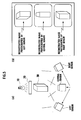
- Figs. 5 (a) and 5 (b) are diagrams for explaining an optical wavefront control pattern generating apparatus according to a second embodiment of the present invention.
- With reference to Figs. 1 to 3, descriptions will be provided for a configuration of an optical wavefront control pattern generating apparatus 1 according to a first embodiment of the present invention. By irradiating an optical
wavefront controller unit 20, in which the optimum optical wavefront control pattern is recorded, with illuminating light 2, the optical wavefront control pattern generating apparatus 1 according to this embodiment is configured to generate the optimum optical wavefront control pattern, which is to be stored in the opticalwavefront controller unit 20, in an image reconstruction system A for displaying a reconstructed image on a reconstructedimage display unit 30. - As shown in Figs. 1 and 2, the optical wavefront control pattern generating apparatus 1 according to this embodiment includes an illuminating
light irradiator unit 10, the opticalwavefront controller unit 20, the reconstructedimage display unit 30, a reconstructedimage detector unit 40, and anoptimizer unit 50. - The illuminating
light irradiator unit 10 is configured to irradiate an optical wavefront control pattern (a hologram), which is displayed on an optical wavefront control device of the opticalwavefront controller unit 20, with illuminating light. - The optical
wavefront controller unit 20 is configured to record an optical wavefront control pattern transmitted from theoptimizer unit 50, and is configured to then display the optical wavefront control pattern on the optical wavefront control device. - The reconstructed
image display unit 30 is configured to display the reconstructed image based onreconstruction light 3 propagated from the opticalwavefront controller unit 20. - In the image reconstruction system A in the optical wavefront control pattern generating apparatus 1 according to this embodiment, at least any one of an amplitude and a phase of the illuminating light 2 irradiated from the illuminating
light irradiator unit 10 is modulated by each pixel of the optical wavefront control pattern displayed on the optical wavefront control device. Thereby, the illuminating light 2 is converted into thereconstruction light 3. Thereconstruction light 3 reaches the reconstructedimage display unit 30 while changing traveling directions thereof, and thus the reconstructed image is displayed. - The reconstructed
image detector unit 40 is configured to detect the reconstructed image displayed on the reconstructedimage display unit 30. Specifically, the reconstructedimage detector unit 40 includes a sensor which makes it possible to detect the reconstructed image displayed on the reconstructedimage display unit 30 with thereconstruction light 3. Thereconstruction light 3 is obtained by modulating at least any one of the amplitude and the phase of the illuminating light 2. - For example, in a case of using a CCD camera as the sensor, the reconstructed
image detector unit 40 photographs the reconstructed image displayed on the reconstructedimage display unit 30 by use of the CCD camera, and transmits, to theoptimizer unit 50, reconstructed image data obtained by digitizing the photographed reconstructed image. - The
optimizer unit 50 is configured to evaluate the reconstructed image detected by the reconstructedimage detector unit 40, and to generate the optimum optical wavefront control pattern by applying a modification process to an optical wavefront control pattern in order for a result of the evaluation to satisfy a predetermined condition. - That is, the
optimizer unit 50 is configured to evaluate, on the basis of the reconstructed image data obtained by digitizing the reconstructed image detected by the above-described sensor, the reconstructed image displayed on the reconstructedimage display unit 30. - Specifically, the
optimizer unit 50 may be configured to generate the optimum optical wavefront control pattern by using a "simulated annealing" method. - That is, the
optimizer unit 50 may be configured to generate the optimum optical wavefront control pattern by repeating an application of a modification process (a Move operation) to an optical wavefront control pattern (a solution prior to the Move operation), a computation of an evaluation value E of a reconstructed image corresponding to an optical wavefront control pattern (a solution obtained after the Move operation) to which the modification process has been applied, and a determination, on the basis of the computed evaluation value E, of whether or not the optical wavefront control pattern (the solution obtained after the Move operation), to which the modification process (the Move operation) has been applied, is to be adopted. - The
optimizer unit 50 may be configured to determine, on the basis of difference information ΔE on evaluation values E for the reconstructed image respectively before and after a modification process (a Move operation), whether or not an optical wavefront control pattern (a solution obtained after the Move operation), to which the modification process (the Move operation) has been applied, is to be adopted. - The
optimizer unit 50 may be configured to determine, on the basis of an adoption probability P defined by the difference information ΔE and a repetitive parameter value (a temperature parameter value T), whether or not the optical wavefront control pattern (the solution after the Move operation), to which the modification process (the Move operation) has been applied, is to be adopted. - The
optimizer unit 50 may be configured to repeat the modification process (the Move operation), computation of the evaluation value E, and the above-described determination until the evaluation values E of the reconstructed image converge on a predetermined repetitive parameter value (a temperature parameter value T). - The
optimizer unit 50 may be configured to vary the above-described repetitive parameter value (the temperature parameter value T) within a predetermined range (a range from a sufficiently high temperature to a sufficiently low temperature). Here, theoptimizer unit 50 may be configured to repeat the modification process (the Move operation), the computation of the evaluation value E, and the above-described determination until the evaluation values E of the reconstructed image converge on each of the repetitive parameter values (the temperature parameter values T) in the predetermined range. - Specifically, as shown in Fig. 3, the
optimizer unit 50 includes an initial optical wavefront controlpattern generator unit 51, a reconstructed imagedata obtaining unit 52, an evaluationvalue computation unit 53, anevaluation unit 54, an optimum optical wavefront controlpattern storage unit 55, an optical wavefront controlpattern modification unit 56, and anoutput unit 57. Incidentally, specific functions of the respective units will be described later. - Referring to Fig. 4, operations of the optical wavefront control pattern generating apparatus according to the first embodiment will be described below.
- Specifically, descriptions will be provided for operations in which, by using the "simulated annealing" method, the
optimizer unit 50 of the optical wavefront control pattern generating apparatus according to this embodiment generates the optimum optical wavefront control pattern (a hologram) to be displayed on the optical wavefront control device of the opticalwavefront controller unit 20, in order that a reconstructed image can be displayed on the reconstructedimage display unit 30. - As shown in Fig. 4, in step S1001, the initial optical wavefront control
pattern generator unit 51 of theoptimizer unit 50 generates an initial optical wavefront control pattern (an initial solution of the optical wavefront control pattern) A0. - For example, in a case of using a liquid crystal panel as the optical wavefront control device, and of using a method of displaying the reconstructed image by modulating an amplitude of the illuminating light 2 through a 256 tone grayscale image projected on the liquid crystal panel, the initial optical wavefront control
pattern generator unit 51 generates the initial optical wavefront control pattern A0 by assigning random values of 0 to 255 respectively to pixels of the grayscale image on the liquid crystal panel. - In a generation process (step S1001) of the initial optical wavefront control pattern A0, when a number of the pixels is defined as "N", an amount of computation is expressed as "O(N)" because it is necessary to define values respectively for all of the pixels.
- In this event, the initial optical wavefront control pattern A0 need not be a random value. The reason is as follows. Nearly 100 % of the Move operations, which worsen solutions, are adopted in a high-temperature state (a state where the temperature parameter value T is large) at the time immediately after an experiment starts regardless of the magnitude of a value taken for the initial optical wavefront control pattern A0. Thus, by sufficiently performing computations with the "simulated annealing" method in a sufficiently high-temperature state, the same effect as in a case of generating a random initial solution can be obtained, and a performance of a solution, which can be finally obtained, is not deteriorated.
- In step S1002, the
output unit 57 of theoptimizer 50 outputs, to the opticalwavefront controller unit 20, the initial optical wavefront control pattern A0 generated by the initial optical wavefront controlpattern generator unit 51. - Moreover, in step S1002, the
output unit 57 of theoptimizer unit 50 outputs, to the opticalwavefront controller unit 20, an initial optical wavefront control pattern A1 modified by the optical wavefront controlpattern modification unit 56. - In step S1003, the illuminating light 2 irradiated by the illuminating
light irradiator unit 10 is modulated to be reconstruction light 2 by the optical wavefront control pattern (Ao or A1) displayed on the optical wavefront control device of the opticalwavefront controller unit 20. Then, the reconstructedimage display unit 30 displays the reconstructed image based on the reconstruction light 2. - Thereafter, by use of the CCD camera, the reconstructed
image detector unit 40 photographs the reconstructed image displayed on the reconstructedimage display unit 30, and digitizes the photographed reconstructed image. After that, the reconstructed imagedata obtaining unit 52 of theoptimizer unit 50 obtains the digitized reconstructed image data from the reconstructedimage detector unit 40. - In step S1004a, the evaluation
value computation unit 53 of theoptimizer unit 50 compares the obtained reconstructed image data with target image data obtained by digitizing a target image previously inputted, and computes the evaluation value E (an evaluation value E0 of the reconstructed image corresponding to the initial optical wavefront control pattern A0) indicating how close the reconstructed image displayed on the reconstructedimage display unit 30 is to the target image. - For example, the evaluation
value computation unit 53 may be configured to compute the evaluation value E of the reconstructed image by taking an absolute value of a difference between a light intensity of the target image at each of coordinate points and a light intensity of the reconstructed image at each of the coordinate points, and thus by adding up the absolute values respectively for all of the coordinate points. In this case, it is postulated that, in each of the target image data and the reconstructed image data, brightness of light of the target image and of the reconstructed image at the respective coordinate points are digitized, and then recorded, for example, respectively with values of 256 tones. - Note that, as the target image data, it is possible to adopt data on an actual photographed image in which the target image is photographed by using a conventional digital camera or the like. In this case, it is possible to generate an "actual photographed hologram" in which a photographed image can be reconstructed. Thereby, it is made possible to apply the present invention to a hologram camera.
- The
evaluation unit 54 of theoptimizer unit 50 determines, on the basis of the computed evaluation value E of the reconstructed image, whether or not an optical wavefront control pattern corresponding to the above reconstructed image is improved. In a case where it is determined that the optical wavefront control pattern is improved (in a case of "Yes" in step S1004a), the operation proceeds to step S1004b. In a case where it is determined that it is not improved (in a case of "No" in step S1004a), the operation proceeds to step S1006. - For example, the
evaluation unit 54 computes difference information ΔE = E(Aj) - E(Aj-1) of the evaluation values of the reconstructed images respectively before and after the modification process to the optical wavefront control pattern. In a case where ΔE < 0 is true, theevaluation unit 54 evaluates that the optical wavefront control pattern Aj is improved. In a case where ΔE < 0 is not true, theevaluation unit 54 evaluates that the optical wavefront control pattern Aj is worsen. - In step S1004b, the
evaluation unit 54 determines whether or not the optical wavefront control pattern Aj is improved as compared to the optimum optical wavefront control pattern stored in the optimum optical wavefront controlpattern storage unit 55. In a case where it is determined that the optical wavefront control pattern Aj is improved (in a case of "Yes" in step S1004b), the operation proceeds to step S1005. In a case where it is determined that it is not improved (in a case of "No" in step S1004b), the operation proceeds to step S1009. - In step S1005, the
evaluation unit 54 stores the above optical wavefront control pattern Aj, as the optimum optical wavefront control pattern, in the optimum optical wavefront controlpattern storage unit 55. - That is, in step S1005, the
evaluation unit 54 determines that the above optical wavefront control pattern Aj is to be adopted as the optimum optical wavefront pattern in a range searched so far. - In addition, the
evaluation unit 54 stores the initial optical wavefront control pattern A0, as the optimum optical wavefront pattern, in the optimum optical wavefront controlpattern storage unit 55 without making the above-described determination. - On the other hand, in step S1006, the
evaluation unit 54 computes an adoption probability P by using equation (1). The adoption probability P indicates a probability of adopting a local modification process (the Move operation) by which the optical wavefront control pattern Aj is computed.
- Here, T denotes a temperature parameter value.
- In step S1007, on the basis of the computed adoption probability P, the
evaluation unit 54 determines whether or not the local modification process, by which the optical wavefront control pattern Aj is computed, is to be adopted. - The
evaluation unit 54 performs an operation in step S1009 in a case where it is determined that the above local modification process is to be adopted. Theevaluation unit 54 performs an operation in step S1008 in a case where it is determined that the above local modification process is not to be adopted. - In step S1008, an optical wavefront control pattern modification unit 46 converts the optical wavefront control pattern Aj back to the optical wavefront control pattern Aj-1 which is in a state prior to the above-described local modification process.
- In step S1009, the
evaluation unit 54 determines whether or not evaluation values Ej of a reconstructed image corresponding to the optical wavefront control pattern Aj converge on the current temperature parameter value T. - Specifically, when computing the optical wavefront control pattern Aj based on the temperature parameter value T, the
evaluation unit 54 determines whether or not a sufficient number of times of the local modification processes are previously performed. In addition, this determination is made with the same method as that used for a determination made with the conventional "simulated annealing" method. - The
evaluation unit 54 performs an operation in step S1101 in a case where it is determined that the evaluation values Ej of the above reconstructed image converge. Theevaluation unit 54 performs an operation in step S1010 in a case where it is determined that the evaluation values Ej of the above reconstructed image do not converge. - In step S1011, the
evaluation unit 54 updates the temperature parameter value T. - In step S1012, the
evaluation unit 54 determines whether or not evaluation values Ej of a reconstructed image corresponding to the optical wavefront control pattern Aj converge on the temperature parameter value T. - Specifically, the
evaluation unit 54 determines whether or not the temperature parameter value T has dropped to a sufficiently low value, i.e., whether or not a sufficient number of times of the local modification processes have been performed. In addition, this determination is made with the same method as that used for a determination made with the conventional "simulated annealing" method. - This operation proceeds to step S1013 in a case where it is determined that a sufficient number of times of the local modification processes have been performed. The operation proceeds to step S1010 in a case where it is determined that a sufficient number of times of the local modification processes have not been performed.
- In step S1010, the optical wavefront control pattern modification unit 46 of the
optimizer unit 50 applies the local modification process to the above optical wavefront control pattern Aj. Here, the local modification process can be defined as a process in which a value for one pixel of the grayscale image on the above-described liquid crystal panel is modified into a random value between 0 and 255. - In step S1013, the
output unit 57 of theoptimizer unit 50 outputs, as the optimum optical wavefront control pattern, an optical wavefront control pattern stored in the optimum optical wavefront controlpattern storage unit 55. (Validation of operating speed in optical wavefront control pattern generating apparatus according to this embodiment) - An operating speed in the optical wavefront control pattern generating apparatus according to this embodiment will be validated below. Specifically, the operating speed in the optical wavefront control pattern generating apparatus according to this embodiment and an operating speed in a conventional technology will be compared with each other. Here, dimensions of a hologram is set to be 128 x 128.
- Adopted as the conventional technology was an example in which a technique, as shown in Non-patent Document 2, for optimizing a Fourier-converted kinoform by using a "simulated annealing" method on the basis of difference information on solutions respectively before and after a Move operation is implemented in a workstation having a 600 MHz dual CPU; and in which a fast Fourier conversion is used for evaluation of a solution.
- As a result of an experiment with the conventional technology as described above, it was possible to evaluate a
reconstructed image 40 times per second on average. - On the other hand, the following steps are considered to be bottlenecks in a computation time concerning each time of evaluation on a reconstructed image in the optical wavefront control pattern generating apparatus according to this embodiment:
- (A) A step where the
optimizer unit 50 records an optical wavefront control pattern in the opticalwavefront controller unit 20; - (B) A step where the reconstructed image detector unit (for example, a CCD camera) 40 photographs a reconstructed image displayed on the reconstructed
image display unit 30, and converts the photographed image into reconstructed image data: - (C) A step where the
optimizer unit 50 computes an evaluation value E based on the reconstructed image data and a target image data; and - (D) A step where the
optimizer unit 50 determines, on the bases of difference information ΔE on evaluation values of the reconstructed image respectively before and after a Move operation, and of a temperature parameter value T, whether or not the Move operation is to be adopted. - In general, it is considered that steps (A) and (B) which depend on a performance of hardware can each be performed 60 times or more per second.
- Meanwhile, it is considered that step (D) can be performed 60 times or more per second when the workstation having a 600 MHz dual CPU is used.
- Step (C) is an operation of computing a difference between each pixel of the reconstructed image data and each pixel of the target image data which is corresponds to each pixel of the reconstructed image data, and an operation of thereafter computing a total of all of the differences. For this reason, by making it possible to perform in parallel the computation with dedicated hardware by using an FPGA or the like, it is made possible to process this step at a higher speed than in a case of normally processing the step by a general computer. Accordingly, it is considered that 60 or more times of step (C) can be executed in every second.
- As has been described above, use of the optical wavefront control pattern generating apparatus according to this present invention makes it possible to generate an optimum optical wavefront control pattern (a hologram) at a higher speed than in the conventional technology.
- According to the optical wavefront control pattern generating apparatus according to this embodiment, an optimum wavefront control pattern is generated in the following manner. The reconstructed
image detector unit 40, such as a CCD camera, detects a reconstructed image actually displayed on the reconstructedimage display unit 30, and theoptimizer unit 50 evaluates the detected reconstructed image. Thereby, it is made possible to solve, as much as possible, the problem with noise, which is practically insoluble with software, through processing with hardware, and to obtain a desired reconstructed image faster and more accurately. - Specifically, according to the optical wavefront control pattern generating apparatus according to this embodiment, the optimum optical wavefront control pattern (the hologram) is generated by using a reconstructed image obtained in an actual image reconstruction system (the optical system) A. Thereby, it is made possible to reduce noise which possibly occurs in a case where an optical wavefront control pattern generated under ideal conditions is applied to the actual image reconstruction system A.
- According to the optical wavefront control pattern generating apparatus according to this embodiment, it is made possible to replace costs for a "step of computing a reconstructed image from a predetermined hologram", which requires the longest computation time when the optimum optical wavefront control pattern (the hologram) is generated by using the "simulated annealing" method, with costs for elements concerning hardware, as to how fast an operation of using the reconstructed
image detector unit 40, such as a CCD camera, can be performed to photograph a reconstructed image generated by actually modulating the illuminating light 2. - With reference to Figs. 5(a) and 5(b), an optical wavefront control pattern generating apparatus according to a second embodiment of the present invention will be described.
- As shown in Fig. 5(a), in the optical wavefront control pattern generating apparatus according to the second embodiment, the optical
wavefront controller unit 20 is configured to modulate at least any one of an amplitude and a phase of illuminating light irradiated by the illuminatinglight irradiator unit 10. The reconstructedimage display unit 30 is configured to display a reconstructed image based on reconstruction light 2 obtained by modulating at least any one of the amplitude and the phase of the illuminating light. - Here, the reconstructed
image detector unit 40 includes a plurality of sensors (for example, CCD cameras) which make it possible to detect the reconstructed image displayed on the reconstructedimage display unit 30. In an example shown in Fig. 5(a), the reconstructedimage detector unit 40 includes a left sensor, a central sensor and a right sensor. - Accordingly, as shown in Fig. 5(b), the reconstructed
image detector unit 40 makes it possible to obtain a plurality of reconstructed images photographed respectively from various angles. - For this reason, the
optimizer unit 50 is configured to evaluate, on the bases of the plurality of reconstructed images detected by the respective plurality of sensors, the reconstructed image displayed on the reconstructedimage display unit 30. - For example, the
optimizer unit 50 is configured to compute reconstructed image data in the form of a three-dimensional image, on the bases of three reconstructed images respectively photographed by the left sensor, the central sensor and the right sensor, and then to compute an optimum optical wavefront control pattern by comparing the computed reconstructed image data in the form of a three-dimensional image with target image data in the form of a three-dimensional image. - In this embodiment, the
optimizer unit 50 may be configured to manage target image data obtained from a direction toward the left side of the target image, that from a direction toward the center thereof, and that from a direction toward the right side thereof, and to compute an optimum optical wavefront control pattern by comparing these target image data respectively with target data obtained by digitizing the three reconstructed images respectively photographed by the left sensor, the central sensor and the right sensor. - As has been described above, the present invention makes it possible to provide an optical wavefront control pattern generating apparatus and an optical wavefront control pattern generating method with which the problem with noise, which is practically insoluble with software, can be solved through processing with hardware; and with which a desired reconstructed image can be obtained faster and more accurately.
Claims (11)
- An optical wavefront control pattern generating apparatus which generates an optimum optical wavefront control pattern which is to be stored in an optical wavefront controller unit, in an image reconstruction system displaying a reconstructed image on a reconstructed image display unit, by irradiating the optical wavefront controller unit, in which an optical wavefront control pattern is recorded, with illuminating light, the apparatus comprising:a reconstructed image detector unit configured to detect a reconstructed image displayed on the reconstructed image display unit; andan optimizer unit configured to evaluate the reconstructed image detected by the reconstructed image detector unit, and to generate the optimum optical wavefront control pattern by applying a modification process to the optical wavefront control pattern in order for a result of the evaluation to satisfy a predetermined condition.
- The optical wavefront control pattern generating apparatus according to claim 1, wherein:the optimizer unit is configured to generate the optimum optical wavefront control pattern, by repeating an application of a modification process to the optical wavefront control pattern, a computation of an evaluation value of a reconstructed image corresponding to the optical wavefront control pattern to which the modification process has been applied, and a determination, on the basis of the evaluation value, of whether or not the optical wavefront control pattern, to which the modification process has been applied, is to be adopted.
- The optical wavefront control pattern generating apparatus according to claim 2, wherein:on the basis of difference information on evaluation values of the reconstructed image respectively before and after the modification process, the optimizer unit is configured to determine whether or not the optical wavefront control pattern, to which the modification process has been applied, is to be adopted.
- The optical wavefront control pattern generating apparatus according to claim 3, wherein:on the basis of the difference information and of an adoption probability determined by a repetitive parameter value, the optimizer unit is configured to determine whether or not the optical wavefront control pattern, to which the modification process has been applied, is to be adopted.
- The optical wavefront control pattern generating apparatus according to claim 4, wherein:the optimizer unit is configured to repeat the application of the modification process, the computation of the evaluation value, and the determination, until the evaluation values of the reconstructed image converge on a predetermined repetitive parameter value.
- The optical wavefront control pattern generating apparatus according to claim 5, wherein:the optimizer unit is configured to vary the predetermined repetitive parameter value within a predetermined range.
- The optical wavefront control pattern generating apparatus according to claim 1, wherein:the optical wavefront controller unit comprises an optical wavefront control device capable of modulating at least any one of an amplitude and a phase of the illuminating light by use of the recorded optical wavefront control pattern.
- The optical wavefront control pattern generating apparatus according to claim 1, wherein:the reconstructed image detector unit comprises a sensor capable of detecting the reconstructed image displayed on the reconstructed image display unit by use of reconstruction light obtained by modulating at least any one of an amplitude and a phase of the illuminating light.
- The optical wavefront control pattern generating apparatus according to claim 8, wherein:the optimizer unit is configured to evaluate the reconstructed image on the basis of the reconstructed image detected by the sensor.
- The optical wavefront control pattern generating apparatus according to claim 1, wherein:the reconstructed image detector unit comprises a plurality of sensors, each capable of detecting the reconstructed image displayed on the reconstructed image display unit by use of reconstruction light obtained by modulating at least any one of an amplitude and a phase of the illuminating light, andthe optimizer unit is configured to evaluate the reconstructed image on the bases of a plurality of reconstructed images respectively detected by the plurality of sensors.
- An optical wavefront control pattern generating method for generating an optimum optical wavefront control pattern which is to be stored in an optical wavefront controller unit, in an image reconstruction system displaying a reconstructed image on a reconstructed image display unit, by irradiating the optical wavefront controller unit, in which an optical wavefront control pattern is recorded, with illuminating light, the method comprising the steps of:detecting a reconstructed image displayed on the reconstructed image display unit;evaluating the reconstructed image detected by a reconstructed image display unit; andgenerating the optimum optical wavefront control pattern by applying a modification process to the optical wavefront control pattern in order for a result of the evaluation to satisfy a predetermined condition.
Applications Claiming Priority (3)
| Application Number | Priority Date | Filing Date | Title |
|---|---|---|---|
| JP2004130243 | 2004-04-26 | ||
| JP2005113425A JP2005338787A (en) | 2004-04-26 | 2005-04-11 | Light wavefront control pattern generation apparatus and light wavefront control pattern generation method |
| PCT/JP2005/007921 WO2005103841A1 (en) | 2004-04-26 | 2005-04-26 | Optical wavefront control pattern generating apparatus and optical wavefront control pattern generating method |
Publications (2)
| Publication Number | Publication Date |
|---|---|
| EP1752838A1 true EP1752838A1 (en) | 2007-02-14 |
| EP1752838A4 EP1752838A4 (en) | 2009-12-02 |
Family
ID=35197143
Family Applications (1)
| Application Number | Title | Priority Date | Filing Date |
|---|---|---|---|
| EP05737037A Withdrawn EP1752838A4 (en) | 2004-04-26 | 2005-04-26 | OPTICAL WAVE FRONT CONTROL MODEL GENERATION APPARATUS AND OPTICAL WAVE FRONT CONTROL MODEL GENERATION METHOD |
Country Status (6)
| Country | Link |
|---|---|
| US (1) | US7800035B2 (en) |
| EP (1) | EP1752838A4 (en) |
| JP (1) | JP2005338787A (en) |
| KR (1) | KR100855292B1 (en) |
| TW (1) | TW200602824A (en) |
| WO (1) | WO2005103841A1 (en) |
Cited By (2)
| Publication number | Priority date | Publication date | Assignee | Title |
|---|---|---|---|---|
| KR100855292B1 (en) * | 2004-04-26 | 2008-08-29 | 가부시키가이샤 엔.티.티.도코모 | Optical wavefront control pattern generation device and optical wavefront control pattern generation method |
| GB2598088A (en) * | 2020-08-05 | 2022-02-23 | Envisics Ltd | Holographic fingerprint |
Families Citing this family (7)
| Publication number | Priority date | Publication date | Assignee | Title |
|---|---|---|---|---|
| JP4966792B2 (en) * | 2007-09-05 | 2012-07-04 | 日本放送協会 | Hologram recording apparatus and hologram recording method |
| JP4964079B2 (en) * | 2007-09-28 | 2012-06-27 | 日本放送協会 | Light control device |
| JP4975007B2 (en) * | 2008-12-11 | 2012-07-11 | 日本放送協会 | Hologram reproduction wavefront control method and apparatus |
| GB2485609B (en) * | 2010-11-22 | 2018-02-14 | Daqri Holographics Ltd | Holographic systems |
| KR101832068B1 (en) * | 2016-10-25 | 2018-02-23 | 한국과학기술원 | System and method for single point holographic imaging using optical phase conjugation |
| KR102095088B1 (en) * | 2017-06-20 | 2020-04-23 | 한국과학기술원 | Apparatus and method for forming 3 dimensional holographic image using non-periodically structured optical elements |
| JP2024067697A (en) * | 2022-11-07 | 2024-05-17 | Kddi株式会社 | Full-color computer generated hologram reproducing device, method and program |
Family Cites Families (10)
| Publication number | Priority date | Publication date | Assignee | Title |
|---|---|---|---|---|
| JP2686098B2 (en) * | 1988-06-20 | 1997-12-08 | 日本電信電話株式会社 | Holographic transmission system |
| JPH0635392A (en) | 1992-07-20 | 1994-02-10 | Fujitsu Ltd | Stereoscopic display |
| JP3918044B2 (en) * | 1996-11-01 | 2007-05-23 | 浜松ホトニクス株式会社 | Image forming apparatus |
| JPH11337737A (en) * | 1998-05-25 | 1999-12-10 | Mitsubishi Chemical Corp | Phase modulation optical element and method of manufacturing the same |
| JPH11337733A (en) * | 1998-05-28 | 1999-12-10 | Sumitomo Bakelite Co Ltd | Birefringent plate and manufacturing method thereof |
| JP4191419B2 (en) | 2002-03-11 | 2008-12-03 | 浜松ホトニクス株式会社 | Computer generated hologram production apparatus and method |
| JP4148406B2 (en) | 2002-12-02 | 2008-09-10 | 大日本印刷株式会社 | How to create a computer generated hologram |
| US7113268B2 (en) * | 2004-01-12 | 2006-09-26 | The Boeing Company | Scintillation tolerant optical field sensing system and associated method |
| JP2005338787A (en) * | 2004-04-26 | 2005-12-08 | Ntt Docomo Inc | Light wavefront control pattern generation apparatus and light wavefront control pattern generation method |
| EP1752839B1 (en) * | 2004-04-26 | 2013-12-04 | NTT DoCoMo, Inc. | Optical wavefront control pattern generating apparatus and optical wavefront control pattern generating method |
-
2005
- 2005-04-11 JP JP2005113425A patent/JP2005338787A/en active Pending
- 2005-04-26 US US11/587,920 patent/US7800035B2/en not_active Expired - Fee Related
- 2005-04-26 EP EP05737037A patent/EP1752838A4/en not_active Withdrawn
- 2005-04-26 TW TW094113290A patent/TW200602824A/en not_active IP Right Cessation
- 2005-04-26 WO PCT/JP2005/007921 patent/WO2005103841A1/en not_active Ceased
- 2005-04-26 KR KR1020067022305A patent/KR100855292B1/en not_active Expired - Fee Related
Cited By (4)
| Publication number | Priority date | Publication date | Assignee | Title |
|---|---|---|---|---|
| KR100855292B1 (en) * | 2004-04-26 | 2008-08-29 | 가부시키가이샤 엔.티.티.도코모 | Optical wavefront control pattern generation device and optical wavefront control pattern generation method |
| GB2598088A (en) * | 2020-08-05 | 2022-02-23 | Envisics Ltd | Holographic fingerprint |
| GB2598088B (en) * | 2020-08-05 | 2022-08-24 | Envisics Ltd | Holographic fingerprint |
| US12072671B2 (en) | 2020-08-05 | 2024-08-27 | Envisics Ltd | Holographic projector having a fault detection circuit and method of using same |
Also Published As
| Publication number | Publication date |
|---|---|
| TWI303753B (en) | 2008-12-01 |
| JP2005338787A (en) | 2005-12-08 |
| KR20070000502A (en) | 2007-01-02 |
| WO2005103841A1 (en) | 2005-11-03 |
| US20090097758A1 (en) | 2009-04-16 |
| US7800035B2 (en) | 2010-09-21 |
| EP1752838A4 (en) | 2009-12-02 |
| TW200602824A (en) | 2006-01-16 |
| KR100855292B1 (en) | 2008-08-29 |
Similar Documents
| Publication | Publication Date | Title |
|---|---|---|
| JP5249202B2 (en) | Phase search and synthesis of phase holograms | |
| RU2434258C2 (en) | Method of calculating digital video holograms and device for realising said method | |
| CN115462183B (en) | Image display device, method for generating training neural network model and computer program | |
| KR101496802B1 (en) | Analytical method for computing video holograms in real time | |
| JP4499331B2 (en) | System and method for recovering wavefront phase information | |
| US20190196400A1 (en) | Hologram generation apparatus and method thereof | |
| US10663923B2 (en) | Efficiently generating a high quality patterned-phase-only hologram for display on a single device | |
| US7800035B2 (en) | Optical wavefront control pattern generating apparatus and optical wavefront control pattern generating method | |
| JP4189879B2 (en) | Generating apparatus, generating method, program, and recording medium | |
| Rong et al. | Reconstruction efficiency enhancement of amplitude-type holograms by using single-scale retinex algorithm | |
| EP1752839B1 (en) | Optical wavefront control pattern generating apparatus and optical wavefront control pattern generating method | |
| CN118817643A (en) | A stacked diffraction imaging method, electronic device and storage medium based on relaxed alternating multiplier method | |
| Shang et al. | Phase retrieval from a single diffraction intensity pattern by generating the support constraint using deep learning | |
| KR20060136472A (en) | Optical wavefront control pattern generating apparatus and optical wavefront control pattern generating method | |
| CN113902819A (en) | Method, apparatus, computer device and storage medium for imaging through scattering medium | |
| Uchiyama et al. | Events meet phase-shifting digital holography: practical acquisition, theory, and algorithms | |
| Magallón et al. | Monte–Carlo Techniques Applied to CGH Generation Processes and Their Impact on the Image Quality Obtained | |
| CN100405130C (en) | Stereoscopic image display device and stereoscopic image display method | |
| KR102454859B1 (en) | Device and method for generating hologram | |
| Lobo-Ruiz et al. | Optimized complex fields for non-iterative generation of phase holograms | |
| JP4718223B2 (en) | Light wavefront control pattern generation apparatus and light wavefront control pattern generation method | |
| Cheng et al. | Two-stage dual-network approach for multi-depth computer-generated holography | |
| Huang et al. | Accelerated CGH Generation for AR Head‐Up Display Based on the Novel YOLO‐MiDaS‐DeepCGH Pipeline | |
| CN1947072A (en) | Light wave front control pattern generation device and light wave front control pattern generation method |
Legal Events
| Date | Code | Title | Description |
|---|---|---|---|
| PUAI | Public reference made under article 153(3) epc to a published international application that has entered the european phase |
Free format text: ORIGINAL CODE: 0009012 |
|
| 17P | Request for examination filed |
Effective date: 20061124 |
|
| AK | Designated contracting states |
Kind code of ref document: A1 Designated state(s): DE GB |
|
| RIN1 | Information on inventor provided before grant (corrected) |
Inventor name: HORIKOSHI, TSUTOMU Inventor name: TSUBOI, MASAHI |
|
| DAX | Request for extension of the european patent (deleted) | ||
| RBV | Designated contracting states (corrected) |
Designated state(s): DE GB |
|
| A4 | Supplementary search report drawn up and despatched |
Effective date: 20091104 |
|
| 17Q | First examination report despatched |
Effective date: 20100923 |
|
| STAA | Information on the status of an ep patent application or granted ep patent |
Free format text: STATUS: THE APPLICATION IS DEEMED TO BE WITHDRAWN |
|
| 18D | Application deemed to be withdrawn |
Effective date: 20111101 |