EP1752814A1 - Justierbare optische Baugruppe mit elastischem Deformationsstegen - Google Patents
Justierbare optische Baugruppe mit elastischem Deformationsstegen Download PDFInfo
- Publication number
- EP1752814A1 EP1752814A1 EP06118065A EP06118065A EP1752814A1 EP 1752814 A1 EP1752814 A1 EP 1752814A1 EP 06118065 A EP06118065 A EP 06118065A EP 06118065 A EP06118065 A EP 06118065A EP 1752814 A1 EP1752814 A1 EP 1752814A1
- Authority
- EP
- European Patent Office
- Prior art keywords
- assembly according
- optical carrier
- optical
- intermediate region
- deformation
- Prior art date
- Legal status (The legal status is an assumption and is not a legal conclusion. Google has not performed a legal analysis and makes no representation as to the accuracy of the status listed.)
- Withdrawn
Links
- 230000003287 optical effect Effects 0.000 title claims abstract description 30
- 239000013013 elastic material Substances 0.000 claims abstract description 3
- 239000000463 material Substances 0.000 claims description 5
- 238000004519 manufacturing process Methods 0.000 description 3
- 238000005452 bending Methods 0.000 description 2
- 239000013078 crystal Substances 0.000 description 2
- 238000004512 die casting Methods 0.000 description 2
- 230000002441 reversible effect Effects 0.000 description 2
- RYGMFSIKBFXOCR-UHFFFAOYSA-N Copper Chemical compound [Cu] RYGMFSIKBFXOCR-UHFFFAOYSA-N 0.000 description 1
- HCHKCACWOHOZIP-UHFFFAOYSA-N Zinc Chemical compound [Zn] HCHKCACWOHOZIP-UHFFFAOYSA-N 0.000 description 1
- 238000004026 adhesive bonding Methods 0.000 description 1
- 229910052802 copper Inorganic materials 0.000 description 1
- 239000010949 copper Substances 0.000 description 1
- 238000011161 development Methods 0.000 description 1
- 230000018109 developmental process Effects 0.000 description 1
- 238000006073 displacement reaction Methods 0.000 description 1
- 230000002427 irreversible effect Effects 0.000 description 1
- 239000002184 metal Substances 0.000 description 1
- 229910052751 metal Inorganic materials 0.000 description 1
- 238000000034 method Methods 0.000 description 1
- 230000002093 peripheral effect Effects 0.000 description 1
- 230000005855 radiation Effects 0.000 description 1
- 239000011701 zinc Substances 0.000 description 1
- 229910052725 zinc Inorganic materials 0.000 description 1
Images

Classifications
-
- G—PHYSICS
- G02—OPTICS
- G02B—OPTICAL ELEMENTS, SYSTEMS OR APPARATUS
- G02B7/00—Mountings, adjusting means, or light-tight connections, for optical elements
- G02B7/02—Mountings, adjusting means, or light-tight connections, for optical elements for lenses
- G02B7/021—Mountings, adjusting means, or light-tight connections, for optical elements for lenses for more than one lens
-
- G—PHYSICS
- G02—OPTICS
- G02B—OPTICAL ELEMENTS, SYSTEMS OR APPARATUS
- G02B7/00—Mountings, adjusting means, or light-tight connections, for optical elements
- G02B7/02—Mountings, adjusting means, or light-tight connections, for optical elements for lenses
- G02B7/023—Mountings, adjusting means, or light-tight connections, for optical elements for lenses permitting adjustment
Definitions
- the invention refers to an adjustable optical assembly, in particular a focusable collimator optics for laser diodes.
- Laser diodes additionally require collimator optics to parallelize the radiation beam.
- collimator optics after the laser diode and the collimator lens have been mounted in an optics carrier, an adjustment of the mutual position relative to one another must take place, which has axial displacements (focus) and inclinations.
- the laser diodes and the collimator lens are fixed during adjustment only after adjustment.
- This fixing process for example, a gluing, requires a period of time, which is disturbing in mass production.
- a centering ring of the laser diode is provided in a collimator, which is axially fixed by a holding member in the housing and can be adjusted in the XY plane with the aid of the adjusting elements which cooperate with a peripheral surface of the centering ring.
- adjustable collimator optics consists of many individual components.
- US6657788 has an adjustable optical assembly with a collimator optics and a prism between these thin, axially oriented and deformable deformation webs, which form around, in a serving as an optical carrier cylinder sleeve circumferentially, holes form through which emitted from the prism partial beams exit.
- An adjustment of the collimator optics does not take place via the plastically deformed deformation webs.
- the object of the invention is the realization of a simple and suitable for mass production adjustable optical assembly with a large adjustment range.
- an optical assembly which can be adjusted relative to an axis has an optical carrier with which at least two optical components are firmly connected, wherein the optical carrier has at least one thin, at least partially tangentially oriented deformation web in the axial intermediate region between the two components.
- the optics carrier is substantially sleeve-shaped (hollow cylindrical or hollow prismatic), whereby suitably shaped components can be arranged coaxially inside.
- a shape corresponds to the axial symmetry.
- a plurality of circumferentially distributed tangentially oriented deformation webs are present, whereby the bending inertia element of the optical carrier is increased in the intermediate region.
- the tangentially oriented deformation webs form a circumferential deformation ring, whereby any tangential normal stresses are compensated via ring stresses.
- the circumferential deformation ring is connected axially on both sides via at least three circumferentially staggered supports to the optical carrier, whereby in each case the bending inertia element of the optical carrier is increased at the edge of the intermediate region.
- each offset by 60 ° supports are present, which are further advantageously arranged per axial side in groups of three staggered by 120 ° supports, whereby the shear-deformable Tangentialin is maximized.
- the optics carrier consists of a highly elastic material, such as, for example, the zinc die casting present in a hexagonal crystal structure, whereby relative to other materials large deformations in the elastic range are present and thus reversible.
- At least three, extending axially over the intermediate region with the at least one deformation web adjusting means present, more advantageously in the form of wedges of the same material, which mediates on the elasticity of the intermediate region and the stiction a reversible and stable adjustment of the module is possible.
- the optical carrier consists of a highly plastic material such as the present in cubic face-centered crystal structure copper die casting, which occur relative to other materials in plastic deformation only small spring back and thus are irreversible.
- the assembly is an adjustable and focusable collimator optics with a collimator lens and a laser diode, whereby an adjustable focused beam source suitable for mass production is realized.
- an optical assembly inclined with respect to an axis A in the form of a focusable collimator optics comprises a sleeve-shaped optical carrier 1 made of metal, with which two optical components in the form of a laser diode 2 and a collimator lens 3 are fixedly connected inside are.
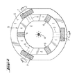
- the optical carrier 1 has in the axial intermediate region X between the two components a plurality of thin, tangentially oriented deformation webs 4, which together form a circumferential deformation ring 5.
- the encircling deformation ring 5 is connected axially on both sides via three supports 6, each offset by 60 ° (one each in the background) to the optical carrier 1. On each axial side three staggered by 120 ° supports 6 are arranged.
- three circumferentially offset by 120 °, axially over the intermediate region X extending adjusting 7 in the form of non-circular rotary wedges present, which are clamped frictional engagement on axial surfaces 8 in the optical carrier 1.
Landscapes
- Physics & Mathematics (AREA)
- General Physics & Mathematics (AREA)
- Optics & Photonics (AREA)
- Mounting And Adjusting Of Optical Elements (AREA)
- Optical Head (AREA)
- Lens Barrels (AREA)
- Optical Couplings Of Light Guides (AREA)
Abstract
Description
- Die Erfindung bezeichnet eine justierbare optische Baugruppe, insbesondere eine fokussierbare Kollimatoroptik für Laserdioden.
- Laserdioden benötigen zur Parallelisierung des Strahlungsbündels zusätzlich eine Kollimatoroptik. Bei einer Kollimatoroptik muss nach der Montage der Laserdiode sowie der Kollimatorlinse in einem Optikträger eine Justierung der gegenseitigen Lage zueinander erfolgen, die axiale Verschiebungen (Fokus) und Neigungen aufweist.
- Bei einfachen Kollimatoroptiken werden bei der Herstellung die Laserdioden und die Kollimatorlinse erst nach dem Justieren fixiert. Dieser Fixierungsprozess, bspw. ein Verkleben, benötigt eine Zeitspanne, welche bei der Massenproduktion störend ist.
- Nach der
DE9002698U ist bei einer Kollimatoroptik ein Zentrierring der Laserdiode vorgesehen, der von einem Haltebauteil im Gehäuse axial festlegbar ist und mit Hilfe der Einstellelemente, die mit einer Umfangsfläche des Zentrierrings zusammenwirken, in der XY-Ebene verstellt werden kann. Diese, jederzeit nachjustierbare Kollimatoroptik besteht aus vielen einzelnen Komponenten. - Nach der
US6657788 weist eine justierbare optische Baugruppe mit einer Kollimatoroptik und einem Prisma zwischen diesen dünne, axial orientierte sowie deformierbare Deformationsstege auf, die sich um, in einer als Optikträger dienenden Zylinderhülse umfänglich versetzte, Löcher ausbilden, durch welche vom Prisma reflektierte Teilstrahlen austreten. Eine Justierung der Kollimatoroptik erfolgt über die plastisch deformierten Deformationsstege nicht. - Die Aufgabe der Erfindung besteht in der Realisierung einer einfachen und zur Massenproduktion geeigneten justierbaren optischen Baugruppe mit grossem Justierbereich.
- Die Aufgabe wird im Wesentlichen durch die Merkmale des Anspruchs 1 gelöst. Vorteilhafte Weiterbildungen ergeben sich aus den Unteransprüchen.
- So weist eine bezüglich einer Achse justierbare optische Baugruppe einen Optikträger auf, mit welchem zumindest zwei optische Bauelemente fest verbunden sind, wobei der Optikträger im axialen Zwischenbereich zwischen den beiden Bauelementen zumindest einen dünnen, zumindest teilweise tangential orientierten Deformationssteg aufweist.
- Durch tangential orientierte Deformationsstege kann bezüglich axialen Deformationsstegen eine relativ grosse Versetzung bereits über kleine Scherdeformationen erzielt werden, wodurch sich ein grosser Justierbereich ergibt.
- Vorteilhaft ist der Optikträger im wesentlichen hülsenförmig (hohlzylindrisch oder hohlprismatisch), wodurch passend ausgeformte Bauelemente koaxial im Inneren angeordnet werden können. Zudem entspricht eine derartige Form der axialen Symmetrie.
- Vorteilhaft sind mehrere, umfänglich zur Achse verteilte tangential orientierte Deformationsstege vorhanden, wodurch das Biegeträgheitselement des Optikträgers im Zwischenbereich erhöht wird.
- Vorteilhaft bilden die tangential orientierten Deformationsstege einen umlaufenden Deformationsring aus, wodurch über Ringspannungen allfällige tangentiale Normalspannungen ausgeglichen werden.
- Vorteilhaft ist der umlaufende Deformationsring axial beidseitig je über zumindest drei, umlaufend jeweils versetzte Stützen mit dem Optikträger verbunden, wodurch jeweils das Biegeträgheitselement des Optikträgers am Rand des Zwischenbereiches erhöht wird.
- Vorteilhaft sind genau sechs jeweils um 60° versetzte Stützen vorhanden, welche weiter vorteilhaft je Axialseite in Gruppen von je drei um 120° versetzte Stützen angeordnet sind, wodurch die scherdeformierbare Tangentiallänge maximiert wird.
- Vorteilhaft besteht der Optikträger aus einem hochelastischen Material wie bspw. der in hexagonaler Kristallstruktur vorliegende Zink-Druckguss, wodurch relativ zu anderen Materialien grosse Deformationen im Elastizitätsbereich liegen und somit reversibel sind.
- Vorteilhaft sind zumindest drei, sich axial über den Zwischenbereich mit dem zumindest einem Deformationssteg erstreckende Justiermittel (Keile, Schrauben, Gewindestifte, Kugeln, etc.) vorhanden, weiter vorteilhaft in Form von Keilen gleichen Materials, wodurch vermittelt über die Elastizität des Zwischenbereichs und der Haftreibung eine reversible sowie stabile Justierung der Baugruppe möglich ist.
- Alternativ vorteilhaft besteht der Optikträger aus einem hochplastischen Material wie bspw. dem in kubisch flächenzentrierter Kristallstruktur vorliegendem Kupfer-Druckguss, wodurch relativ zu anderen Materialien bei plastischen Deformationen nur kleine Rückfederungen auftreten und somit irrreversibel sind.
- Vorteilhaft ist die Baugruppe eine justier- und fokussierbare Kollimatoroptik mit einer Kollimatorlinse und einer Laserdiode, wodurch eine zur Massenproduktion geeignete justierbare fokussierte Strahlquelle realisiert ist.
- Die Erfindung wird bezüglich eines vorteilhaften Ausführungsbeispiels näher erläutert mit:
- Fig. 1 als optische Baugruppe in Seitenansicht
- Fig. 2 als Querschnitt in der Ebene II - II der Fig. 1
- Nach Fig. 1 und Fig. 2 weist eine bezüglich einer Achse A geneigt justierte optische Baugruppe in Form einer fokussierbaren Kollimatoroptik einen hülsenförmigen Optikträger 1 aus Metall auf, mit welchem koaxial im Inneren zwei optische Bauelemente in Form einer Laserdiode 2 und einer Kollimatorlinse 3 fest verbunden sind. Der Optikträger 1 weist im axialen Zwischenbereich X zwischen den beiden Bauelementen mehrere dünne, tangential orientierte Deformationsstege 4 auf, die zusammen einen umlaufenden Deformationsring 5 ausbilden. Der umlaufende Deformationsring 5 ist axial beidseitig je über je drei, umlaufend jeweils um 60° versetzte Stützen 6 (je einer verdeckt im Hintergrund) mit dem Optikträger 1 verbunden. An jeder Axialseite sind je drei um 120° versetzte Stützen 6 angeordnet. Zusätzlich sind drei, umlaufend jeweils um 120° versetzte, sich axial über den Zwischenbereich X erstreckende Justiermittel 7 in Form von unrunden Drehkeilen vorhanden, die reibkraftschlüssig an Axialflächen 8 im Optikträger 1 verspannt sind.
Claims (10)
- Bezüglich einer Achse (A) justierbare optische Baugruppe mit einem Optikträger (1), mit welchem zumindest zwei optische Bauelemente (2, 3) fest verbunden sind, dadurch gekennzeichnet, dass der Optikträger (1) im axialen Zwischenbereich (X) zwischen den beiden Bauelementen (2, 3) zumindest einen dünnen, zumindest teilweise tangential orientierten Deformationssteg (4) aufweist.
- Baugruppe nach Anspruch 1, dadurch gekennzeichnet, dass der Optikträger (1) hülsenförmig ist.
- Baugruppe nach Anspruch 1 oder 2, dadurch gekennzeichnet, dass mehrere, umfänglich zur Achse (A) verteilte tangential orientierte Deformationsstege (4) vorhanden sind.
- Baugruppe nach Anspruch 3, dadurch gekennzeichnet, dass die tangential orientierten Deformationsstege (4) einen umlaufenden Deformationsring (5) aus bilden.
- Baugruppe nach Anspruch 4, dadurch gekennzeichnet, dass der umlaufende Deformationsring (5) axial beidseitig je über zumindest drei, umlaufend jeweils versetzte Stützen (6) mit dem Optikträger (1) verbunden ist.
- Baugruppe nach Anspruch 5, dadurch gekennzeichnet, dass genau sechs jeweils um 60° versetzte Stützen (6) vorhanden sind, welche je Axialseite in Gruppen von je drei um 120° versetzte Stützen (6) angeordnet sind.
- Baugruppe nach einem der Ansprüche 1 bis 6, dadurch gekennzeichnet, dass der Optikträger (1) aus einem hochelastischen Material besteht.
- Baugruppe nach Anspruch 7, dadurch gekennzeichnet, dass zumindest drei, sich axial über den Zwischenbereich (X) erstreckende Justiermittel (7) vorhanden sind.
- Baugruppe nach einem der Ansprüche 1 bis 6, dadurch gekennzeichnet, dass der Optikträger (1) aus einem hochplastischen Material besteht.
- Baugruppe nach einem der Ansprüche 1 bis 9, dadurch gekennzeichnet, dass sie eine justier- und fokussierbare Kollimatoroptik mit einer Kollimatorlinse (3) und einer Laserdiode (2) ist.
Applications Claiming Priority (1)
| Application Number | Priority Date | Filing Date | Title |
|---|---|---|---|
| DE102005037631A DE102005037631A1 (de) | 2005-08-09 | 2005-08-09 | Justierbare optische Baugruppe |
Publications (1)
| Publication Number | Publication Date |
|---|---|
| EP1752814A1 true EP1752814A1 (de) | 2007-02-14 |
Family
ID=37067439
Family Applications (1)
| Application Number | Title | Priority Date | Filing Date |
|---|---|---|---|
| EP06118065A Withdrawn EP1752814A1 (de) | 2005-08-09 | 2006-07-28 | Justierbare optische Baugruppe mit elastischem Deformationsstegen |
Country Status (4)
| Country | Link |
|---|---|
| US (1) | US20070035854A1 (de) |
| EP (1) | EP1752814A1 (de) |
| JP (1) | JP2007047793A (de) |
| DE (1) | DE102005037631A1 (de) |
Families Citing this family (2)
| Publication number | Priority date | Publication date | Assignee | Title |
|---|---|---|---|---|
| CN111219570A (zh) * | 2018-11-27 | 2020-06-02 | 西安华科光电有限公司 | 一种光学仪器的角度调节机构 |
| DE102019122047B4 (de) * | 2019-08-16 | 2024-06-13 | Precitec Gmbh & Co. Kg | Ausrichteinheit, Sensormodul umfassend dieselbe und Laserbearbeitungssystem umfassend das Sensormodul |
Citations (4)
| Publication number | Priority date | Publication date | Assignee | Title |
|---|---|---|---|---|
| DE9002698U1 (de) * | 1990-03-08 | 1990-05-10 | Schäfter + Kirchhoff, 2000 Hamburg | Kollimator für Laserdioden |
| US5270870A (en) * | 1992-12-23 | 1993-12-14 | Eastman Kodak Company | Athermalized beam source and collimator lens assembly |
| US5303080A (en) * | 1993-04-01 | 1994-04-12 | Eastman Kodak Company | Beam scanning system including actively-controlled optical head |
| US6657788B2 (en) * | 1999-05-17 | 2003-12-02 | Toolz, Ltd. | Methods and apparatus for laser device adjustment |
Family Cites Families (3)
| Publication number | Priority date | Publication date | Assignee | Title |
|---|---|---|---|---|
| US4541689A (en) * | 1983-09-19 | 1985-09-17 | Optical Storage International | Friction wedge alignment system for laser diode collimator pens |
| US4740057A (en) * | 1985-12-18 | 1988-04-26 | Hughes Aircraft Company | Wire like column spacers under a force in excess of Euler's column load |
| US5882106A (en) * | 1997-12-10 | 1999-03-16 | Galli; Robert | Thin profile laser pointer assembly |
-
2005
- 2005-08-09 DE DE102005037631A patent/DE102005037631A1/de not_active Withdrawn
-
2006
- 2006-07-28 EP EP06118065A patent/EP1752814A1/de not_active Withdrawn
- 2006-08-08 JP JP2006215792A patent/JP2007047793A/ja not_active Withdrawn
- 2006-08-09 US US11/501,989 patent/US20070035854A1/en not_active Abandoned
Patent Citations (4)
| Publication number | Priority date | Publication date | Assignee | Title |
|---|---|---|---|---|
| DE9002698U1 (de) * | 1990-03-08 | 1990-05-10 | Schäfter + Kirchhoff, 2000 Hamburg | Kollimator für Laserdioden |
| US5270870A (en) * | 1992-12-23 | 1993-12-14 | Eastman Kodak Company | Athermalized beam source and collimator lens assembly |
| US5303080A (en) * | 1993-04-01 | 1994-04-12 | Eastman Kodak Company | Beam scanning system including actively-controlled optical head |
| US6657788B2 (en) * | 1999-05-17 | 2003-12-02 | Toolz, Ltd. | Methods and apparatus for laser device adjustment |
Also Published As
| Publication number | Publication date |
|---|---|
| US20070035854A1 (en) | 2007-02-15 |
| JP2007047793A (ja) | 2007-02-22 |
| DE102005037631A1 (de) | 2007-02-15 |
Similar Documents
| Publication | Publication Date | Title |
|---|---|---|
| EP1472562B1 (de) | Facettenspiegel mit mehreren spiegelfacetten | |
| DE19506765C2 (de) | Optischer Reflektor | |
| DE19825716A1 (de) | Baugruppe aus optischem Element und Fassung | |
| DE102018106012B3 (de) | Justierbare Spiegelbaugruppe mit Blattfederelement | |
| EP1735651A2 (de) | Optisches element und halterung für ein optisches element | |
| DE102008035224B4 (de) | Laseroszillator mit einer Befestigungskonstruktion für ein optisches Element | |
| EP2135124A1 (de) | Optikfassung und optisches bauelement mit einer derartigen optikfassung | |
| DE102013104159A1 (de) | Thermisch kompensierte optische Baugruppe mit einem formschlüssig gehaltenen optischen Bauelement | |
| EP1899756A2 (de) | Anordnung zur lagerung eines optischen bauelements | |
| DE19812021A1 (de) | Aktiver Spiegel | |
| DE102010022934A1 (de) | Optische Baugruppe | |
| EP2606390B1 (de) | Mehrstufig justierbare fassungsbaugruppe für zwei optische bauteile | |
| EP1574808B1 (de) | Zielfernrohr | |
| CH698665B1 (de) | Justierbare optische Baugruppe. | |
| EP3765883B1 (de) | Justierfassung zur radialen justierung einer optischen einheit mit einer optischen achse | |
| DE102011080819A1 (de) | Facettenspiegel aus Facettenmodulen mit mehreren Facetten | |
| DE102005037631A1 (de) | Justierbare optische Baugruppe | |
| DE10158216A1 (de) | Spiegel, optisches Abbildungssystem und deren Verwendung | |
| EP1515172B1 (de) | Spannungsarme Optikfassung | |
| EP1053576A1 (de) | Verfahren zum aufbauen und verbinden von optischen komponenten, insbesondere von optischen komponenten in einem laserresonator und laserresonator | |
| DE102020134653B3 (de) | Justierbarer Optikhalter für ein optisches Element | |
| DE4029075C1 (de) | ||
| EP1666944B1 (de) | Optischer Faserkoppler | |
| EP3214479B1 (de) | Vorrichtung zur deformation eines optischen elements und optisches element mit der vorrichtung | |
| WO2005111687A1 (de) | Halterung für optische elemente und verfahren zur herstellung eines optischen systems mit einer solchen halterung |
Legal Events
| Date | Code | Title | Description |
|---|---|---|---|
| PUAI | Public reference made under article 153(3) epc to a published international application that has entered the european phase |
Free format text: ORIGINAL CODE: 0009012 |
|
| AK | Designated contracting states |
Kind code of ref document: A1 Designated state(s): AT BE BG CH CY CZ DE DK EE ES FI FR GB GR HU IE IS IT LI LT LU LV MC NL PL PT RO SE SI SK TR |
|
| AX | Request for extension of the european patent |
Extension state: AL BA HR MK YU |
|
| 17P | Request for examination filed |
Effective date: 20070814 |
|
| 17Q | First examination report despatched |
Effective date: 20070914 |
|
| AKX | Designation fees paid |
Designated state(s): CH DE FR GB IT LI SE |
|
| STAA | Information on the status of an ep patent application or granted ep patent |
Free format text: STATUS: THE APPLICATION IS DEEMED TO BE WITHDRAWN |
|
| 18D | Application deemed to be withdrawn |
Effective date: 20080125 |