EP1752626B1 - Elektromagnetisch angetriebens Ventil - Google Patents
Elektromagnetisch angetriebens Ventil Download PDFInfo
- Publication number
- EP1752626B1 EP1752626B1 EP06117898A EP06117898A EP1752626B1 EP 1752626 B1 EP1752626 B1 EP 1752626B1 EP 06117898 A EP06117898 A EP 06117898A EP 06117898 A EP06117898 A EP 06117898A EP 1752626 B1 EP1752626 B1 EP 1752626B1
- Authority
- EP
- European Patent Office
- Prior art keywords
- electromagnet
- valve
- electromagnetically driven
- disc
- coils
- Prior art date
- Legal status (The legal status is an assumption and is not a legal conclusion. Google has not performed a legal analysis and makes no representation as to the accuracy of the status listed.)
- Expired - Fee Related
Links
Images
Classifications
-
- F—MECHANICAL ENGINEERING; LIGHTING; HEATING; WEAPONS; BLASTING
- F01—MACHINES OR ENGINES IN GENERAL; ENGINE PLANTS IN GENERAL; STEAM ENGINES
- F01L—CYCLICALLY OPERATING VALVES FOR MACHINES OR ENGINES
- F01L9/00—Valve-gear or valve arrangements actuated non-mechanically
- F01L9/20—Valve-gear or valve arrangements actuated non-mechanically by electric means
- F01L9/21—Valve-gear or valve arrangements actuated non-mechanically by electric means actuated by solenoids
- F01L2009/2105—Valve-gear or valve arrangements actuated non-mechanically by electric means actuated by solenoids comprising two or more coils
- F01L2009/2109—The armature being articulated perpendicularly to the coils axes
-
- H—ELECTRICITY
- H01—ELECTRIC ELEMENTS
- H01F—MAGNETS; INDUCTANCES; TRANSFORMERS; SELECTION OF MATERIALS FOR THEIR MAGNETIC PROPERTIES
- H01F7/00—Magnets
- H01F7/06—Electromagnets; Actuators including electromagnets
- H01F7/08—Electromagnets; Actuators including electromagnets with armatures
- H01F7/16—Rectilinearly-movable armatures
- H01F2007/1692—Electromagnets or actuators with two coils
-
- H—ELECTRICITY
- H01—ELECTRIC ELEMENTS
- H01F—MAGNETS; INDUCTANCES; TRANSFORMERS; SELECTION OF MATERIALS FOR THEIR MAGNETIC PROPERTIES
- H01F7/00—Magnets
- H01F7/06—Electromagnets; Actuators including electromagnets
- H01F7/08—Electromagnets; Actuators including electromagnets with armatures
- H01F7/14—Pivoting armatures
-
- H—ELECTRICITY
- H01—ELECTRIC ELEMENTS
- H01F—MAGNETS; INDUCTANCES; TRANSFORMERS; SELECTION OF MATERIALS FOR THEIR MAGNETIC PROPERTIES
- H01F7/00—Magnets
- H01F7/06—Electromagnets; Actuators including electromagnets
- H01F7/08—Electromagnets; Actuators including electromagnets with armatures
- H01F7/18—Circuit arrangements for obtaining desired operating characteristics, e.g. for slow operation, for sequential energisation of windings, for high-speed energisation of windings
- H01F7/1844—Monitoring or fail-safe circuits
Definitions
- the invention generally relates to an electromagnetically driven valve and, more particularly, to a pivot-type electromagnetically driven valve for use in an internal combustion engine which is driven by elastic force and electromagnetic force.
- Another problem with the related art is that when the discs are in a neutral position, the air gap is large, and the valve cannot be moved easily unless increased electric power is supplied.
- Still another problem is that, due to variations in dimensions and mounting precision, the core and the discs do not make completely close contact with each other, and therefore fail to obtain desired electromagnetic force, resulting in unstable operation of the valve.
- an electromagnetically driven valve that operates by a combination of electromagnetic force and elastic force includes a valve element that has a valve shaft and that reciprocates in directions of extension of the valve shaft, a first oscillating member and a second oscillating member that extend from driving ends to pivoting ends, and that pivot about central axes extending at the pivoting ends, as well as an electromagnet that oscillates the first oscillating member and the second oscillating member.
- the driving ends are operatively linked with the valve element.
- the electromagnetically driven valve also includes a first measuring portion and a second measuring portion that measure at least one of an oscillation angle, an amount of lift and an oscillating speed of the first oscillating member and the second oscillating member, and a control portion that computes energization control logics based on measurement values provided by the first measuring portion and the second measuring portion, and that averages the energization control logics to control energization of the electromagnet.
- the electromagnetically driven valve in the one aspect performs control by averaging the movements of the plurality of oscillating members, the control in this aspect achieves higher precision than the control that is based on the movement of one disc on the assumption that the other disc or discs move in the same manner.
- the control in this aspect achieves higher precision than the control that is based on the movement of one disc on the assumption that the other disc or discs move in the same manner.
- control portion may determine an amount of electric current supplied to the electromagnet and a duration of flow of electric current through the electromagnet.
- the electromagnet may include a plurality of coils, and the plurality of coils may be connected with each other, or separated.
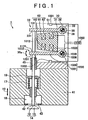
- FIG. 1 is a cross-sectional view of an electromagnetically driven valve in accordance with the embodiment of the invention.
- the electromagnetically driven valve 1 in accordance with the embodiment of the invention has a main body 51, an electromagnet 60 attached to the main body 51, and an upper disc 30 and a lower disc 1030 located at opposite sides of the electromagnet 60, as well as a valve element 14 that is driven by the discs 30, 1030.
- the main body 51 is a base member, to which various components are attached.
- the electromagnet 60 is attached to the main body 51 has a core 61 that is made of a magnetic material, and coils 62, 162 wound on the core 61. Energization of the coils 62, 162 creates magnetic fields, which drive the disc 30 and the disc 1030.
- the discs 30, 1030 are disposed so as to sandwich the electromagnet 60, and one of the discs 30, 1030 is attracted to the electromagnet 60.
- the discs 30, 1030 both reciprocate in such a direction as to approach the electromagnet 60 and in such a direction as to move away from the electromagnet 60.
- the reciprocating movements thereof are transferred to a valve stem 12 via a stem 1012.
- the electromagnetically driven valve 1 is an electromagnetically driven valve that operates by combination of electromagnetic force and elastic force.
- the electromagnetically driven valve 1 includes the valve element 14 that has the valve stem 12 as a valve shaft and that reciprocates in the directions (arrows 10) of extension of the valve stem 12, and the main body 51 as a support member that is provided at a position spaced from the valve element 14.
- the electromagnetically driven valve 1 further includes the discs 30, 1030 as first and second oscillating members that extend from driving ends 32, 1032 to pivoting ends 33, 1033, and that pivot about central axes 35, 1035 extending at the pivoting ends 33, 1033.
- the driving ends 32, 1032 are operatively linked with the valve stem 12.
- energization control logic is a control logic that controls the amount of electric current through the coil 62, 162 of the electromagnet 60 that oscillates the discs 30, 1030. In the energization control logic, the current value is maintained larger than 0A.
- the electromagnetically driven valve 1 in this embodiment is adopted for the intake valves or exhaust valves of internal combustion engines such as gasoline engines, diesel engines, etc.
- the valve element 14 is an intake valve disposed in an intake port 18, the invention is also applicable to a valve element provided as an exhaust valve.
- the electromagnetically driven valve 1 is a pivot drive type electromagnetically driven valve, and employs two discs, that is, the discs 30, 1030, as a motion mechanism.
- the main body 51 is provided on a cylinder head 41.
- the disc 1030 is provided at a lower side
- the disc 30 is provided at an upper side.
- the electromagnet 60 is positioned between the disc 30 and the disc 1030.
- the electromagnet 60 includes the core 61 formed by stacking electromagnetic steel plates, and the coils 62, 162 wound on the core 61 for creating magnetic fields. Supplying electric current through the coils 62, 162 creates magnetic fields in regions surrounded by the coils 62, 162. Due to these magnetic fields, the electromagnet 60 can pull the disc 30 and the disc 1030. Specifically, due to a control of the timing of supplying current through the coils 62, 162, the electromagnet 60 can pull the disc 30 or the disc 1030.
- the coil 62 facing the disc 30, and the coil 162 facing the disc 1030 may be interconnected or separated from each other.
- the number of turns of each coil 62, 162 on the core 61 is not particularly limited.
- Each of the disc 30 and the disc 1030 has an arm portion 31, 1031 and a bearing portion 38, 1038.
- the arm portion 31, 1031 extends from the driving end 32, 1032 to the pivoting end 33, 1033.
- Each arm portion 31, 1031 is a member that is attracted by the electromagnet 60 so as to oscillate (pivot) in the directions indicated by arrows 30a.
- the bearing portion 38, 1038 is provided at an end of the arm portion 31, 1031.
- the arm portions 31, 1031 are pivotable about the bearing portions 38, 1038.
- An upper surface 1131 of the arm portion 1031 is capable of contacting a face of the electromagnet 60 where the coil 162 is provided.
- a lower surface 231 of the arm portion 31 is capable of contacting a face of the electromagnet 60 where the coil 62 is provided.
- a lower surface 1231 of the arm portion 1031 is in contact with the valve stem 12.
- Each bearing portion 38, 1038 has a cylindrical shape, and has therein a torsion bar 36, 1036.
- a first end portion of the torsion bar 36, 1036 is fitted to the main body 51 by spline fitting, and the other end portion thereof is fitted to the bearing portion 38, 1038. Therefore, when the bearing portion 38, 1038 is pivoted, a force opposing this pivot is transferred from the torsion bar 36, 1036 to the bearing portion 38, 1038.
- each bearing portion 38, 1038 is always urged toward a neutral position.
- the disc 1030 receives, on the driving end 1032 side, receives force from the disc 30 via the stem 1012, and therefore presses the valve stem 12.
- a hydro-lash adjuster or the like may be provided between the valve stem 12 and the disc 1030.
- the valve stem 12 is guided by stem guide 45, 43.
- the first measuring portion 1001 and the second measuring portion 1002 are attached to the main body 51.
- the first measuring portion 1001, and the second measuring portion 1002 face the upper surface 131 of the disc 30, and the lower surface 1231 of the disc 1030, respectively. They measure at least one of the oscillation angle (pivot angle), the amount of lift, and the oscillating speed of the disc 30 and the disc 1030.
- Measurement data obtained via the first measuring portion 1001 and the second measuring portion 1002 is sent to the ECU 1000.
- the ECU 1000 determines at least one of the magnitude of electric current supplied through the coils 62, 162, and the supplying timing. More specifically, there is slight difference between the oscillating movements (the oscillation angle, the amount of lift, the oscillating speed) of the disc 30 and the oscillating movements of the disc 1030. Therefore, the ECU 1000 averages the energization control logics which are computed based on the data regarding the disc 30 measured by the first measuring portion 1001 and the data regarding the disc 1030 measured by the second measuring portion 1002. The ECU 1000 computes energization control logic for electrifying the coils 62, 162 on the basis of the average value, that is, supplying electric current through the coils 62, 162.
- the ECU 1000 has a function of determining the amount of electric current supplied to the coils 62, 162 and the duration of flow of electric current therethrough.
- the main body 51 of the electromagnetically driven valve 1 is mounted on the cylinder head 41.
- the intake port 18 is provided in a lower portion of the cylinder head 41.
- the intake port 18 is a path for introducing intake air into a combustion chamber. That is, air-fuel mixture or air passages through the intake port 18.
- a valve seat 42 is provided between the intake port 18 and the combustion chamber. By the valve seat 42, the salability of the valve element 14 can be enhanced.
- the valve element 14 as an intake valve is mounted in the cylinder head 41.
- the valve element 14 includes the valve stem 12 extending in the longitudinal directions, and a bell portion 13 attached to an end portion of the valve stem 12.
- the valve stem 12 is guided by a stem guide 43.
- the valve element 14 is capable of being reciprocated in the directions indicated by the arrows 10.
- a spring retainer 19 is fitted over the valve stem 12.
- the spring retainer 19 is urged by a valve spring 17. Therefore, the valve stem 12 receives upward force from the valve spring 17.
- the arm portions 31, 1031 need to be moved downward. To that end, the current flowing through the coil 162 is stopped or reduced. As a result, the electromagnetic force acting between the electromagnet 60 and the arm portion 1031 reduces. The torsion force (elastic forces) acting on the arm portions 31, 1031 from the torsion bars 36, 1036 overcomes the electromagnetic force, so that the arm portions 31, 1031 move to the neutral position as shown in FIG. 1 . At this time, the valve stem 12 of the valve element 14 is pushed by the arm portions 31, 1031 to move downward. Then, electric current is supplied to the coil 62. As a result, a magnetic field is created around the coil 62, and the arm portion 31 made of a magnetic material is pulled to the electromagnet 60.
- the valve stem 12 of the valve element 14 is pushed by the arm portions 31, 1031 to move downward.
- the pulling force of the electromagnet 60 overcomes the torsion force of the torsion bars 36, 1036, so that finally the lower surface 231 of the arm portion 31 contacts the electromagnet 60.
- the valve element 14 moves downward to assume an open valve state.
- the arm portions 31, 1031 pivot back and forth in the directions indicated by the arrows 30a.
- the bearing portions 38, 1038 connected to the arm portions 31, 1031 also pivot.
- the oscillation angle, the amount of lift and the oscillating speed of the discs 30, 1030 are measured by the first measuring portion 1001 and the second measuring portion 1002, respectively.
- the ECU 1000 prepares dedicated control logics for the discs 30, 1030 separately. By combining these control logics, the ECU 1000 determines the amount of electric current supplied to the coils 62, 162 and the duration of energization so as to control the electromagnet 60.
- the control of energization of the electromagnet 60 is performed on the basis of the movements of the two discs 30, 1030, so that the precision of the control improves as compared with the case where only one disc is monitored to perform the energization control. Therefore, it becomes possible to provide an electromagnetically driven valve capable of reliable operation.
- This invention can be used, for example, in the field of electromagnetically driven valves for internal combustion engines that are mounted in vehicle.
- An electromagnetically driven valve (1) includes a valve stem (12), a valve element (14) that reciprocates in the directions of extension of the valve stem (12), and an upper disc (30) and a lower disc (1030) that extend from driving ends (32, 1032) to pivoting ends (33, 1033), and that pivot about central axes (35, 1035) extending at the pivoting ends (33, 1033).
- the driving ends (32, 1032) are operatively linked with the valve element (14),
- An electromagnet (60) oscillates the upper disc (30) and the lower disc (1030).
- First and second measuring portions (1001, 1002) measure at least one of the oscillation angle, the amount of lift and the oscillating speed of the upper disc (30) and the lower disc (1030).
- An ECU (1000) as a control portion computes energization control logics on the basis of measurement values provided by the first and second measuring portions (1001, 1002), and averages the various energization control logics and accordingly controls the energization of the electromagnet (60).
Claims (4)
- Elektromagnetisch angetriebenes Ventil, das durch eine Kombination einer elektromagnetischen Kraft und einer Federkraft arbeitet,
umfassendein Ventilelement (41), das eine Ventilstange (12) aufweist und das sich in Erstreckungsrichtungen der Ventilstange (12) hin- und herbewegt,ein erstes Schwingungselement (30) und ein zweites Schwingungselement (1030), die sich jeweils von Antriebsenden (32, 1032) zu Schwenkenden (33, 1033) erstrecken, und die sich um Mittelachsen (35, 1035) drehen, die sich bei den Schwenkenden (33, 1033) erstrecken, wobei die Antriebsenden (32, 1032) betriebsfähig mit dem Ventilelement (14) verbunden sind,einen Elektromagneten (60), der das erste Schwingungselement (30) und das zweite Schwingungselement (1030) in Schwingung versetzt,einen ersten Messabschnitt (1001) und einen zweiten Messabschnitt (1002), die zumindest einen Schwingungswinkel, eine Hubgröße und/oder eine Schwingungsgeschwindigkeit des ersten Schwingungselements (30) und des zweiten Schwingungselements (1030) messen, undeinen Steuerungsabschnitt (1000), der auf der Grundlage von Messwerten, die durch den ersten Messabschnitt (1001) und den zweiten Messabschnitt (1002) bereitgestellt werden, eine Energieversorgungssteuerlogik berechnet, und der die Energieversorgungssteuerlogik mittelt, um eine Energieversorgung des Elektromagneten zu steuern. - Elektromagnetisch angetriebenes Ventil nach Anspruch 1, wobei der Steuerungsabschnitt (1000) eine Größe eines dem Elektromagneten (60) zugeführten elektrischen Stromes und eine Flussdauer des elektrischen Stromes durch den Elektromagneten (60) bestimmt.
- Elektromagnetisch angetriebenes Ventil nach Anspruch 1, wobei der Elektromagnet (60)eine Vielzahl von Spulen (62, 162) umfasst, wobei die Vielzahl von Spulen (62, 162) miteinander verbunden ist.
- Elektromagnetisch angetriebenes Ventil nach Anspruch 1, wobei der Elektromagnet (60) eine Vielzahl von Spulen (62, 162) umfasst, wobei die Vielzahl von Spulen (62, 162) getrennt ist.
Applications Claiming Priority (1)
| Application Number | Priority Date | Filing Date | Title |
|---|---|---|---|
| JP2005229682A JP2007046503A (ja) | 2005-08-08 | 2005-08-08 | 電磁駆動弁 |
Publications (2)
| Publication Number | Publication Date |
|---|---|
| EP1752626A1 EP1752626A1 (de) | 2007-02-14 |
| EP1752626B1 true EP1752626B1 (de) | 2008-08-27 |
Family
ID=37402608
Family Applications (1)
| Application Number | Title | Priority Date | Filing Date |
|---|---|---|---|
| EP06117898A Expired - Fee Related EP1752626B1 (de) | 2005-08-08 | 2006-07-26 | Elektromagnetisch angetriebens Ventil |
Country Status (5)
| Country | Link |
|---|---|
| US (1) | US7353787B2 (de) |
| EP (1) | EP1752626B1 (de) |
| JP (1) | JP2007046503A (de) |
| CN (1) | CN100424324C (de) |
| DE (1) | DE602006002452D1 (de) |
Families Citing this family (5)
| Publication number | Priority date | Publication date | Assignee | Title |
|---|---|---|---|---|
| JP5025195B2 (ja) * | 2006-09-13 | 2012-09-12 | 本田技研工業株式会社 | エンジンの電磁動弁装置 |
| US20100059003A1 (en) * | 2006-09-13 | 2010-03-11 | Honda Motor Co., Ltd. | Engine electromagnetic valve operating device |
| JP4691009B2 (ja) * | 2006-12-12 | 2011-06-01 | 本田技研工業株式会社 | エンジンの電磁動弁装置 |
| JP4706781B2 (ja) * | 2009-07-15 | 2011-06-22 | トヨタ自動車株式会社 | 電磁駆動弁 |
| DE102013207461A1 (de) * | 2013-04-24 | 2014-10-30 | Bela Mohacsi | Elektromagnetischer Antrieb |
Family Cites Families (25)
| Publication number | Priority date | Publication date | Assignee | Title |
|---|---|---|---|---|
| JP2610187B2 (ja) * | 1989-04-28 | 1997-05-14 | 株式会社いすゞセラミックス研究所 | バルブの駆動装置 |
| DE19712669C2 (de) * | 1997-03-26 | 2000-03-30 | Daimler Chrysler Ag | Elektromagnetisch gesteuertes Ventil |
| JPH11101110A (ja) * | 1997-09-26 | 1999-04-13 | Nissan Motor Co Ltd | 電磁バルブの駆動装置 |
| JP3550989B2 (ja) | 1997-12-08 | 2004-08-04 | トヨタ自動車株式会社 | 電磁バルブ用駆動装置 |
| US6516758B1 (en) * | 1998-11-16 | 2003-02-11 | Heinz Leiber | Electromagnetic drive |
| JP3835024B2 (ja) * | 1998-11-19 | 2006-10-18 | トヨタ自動車株式会社 | 内燃機関の電磁駆動装置 |
| DE19928006A1 (de) * | 1999-06-18 | 2000-12-21 | Heinz Leiber | Adaptive Actuatorverstellung |
| IT1310488B1 (it) * | 1999-09-23 | 2002-02-18 | Magneti Marelli Spa | Attuatore elettromagnetico per il comando delle valvole di un motore ascoppio. |
| FR2799302B1 (fr) | 1999-10-04 | 2002-01-18 | Peugeot Citroen Automobiles Sa | Actionneur electrique notamment pour soupape de moteur de vehicule automobile |
| ITBO20000127A1 (it) * | 2000-03-09 | 2001-09-09 | Magneti Marelli Spa | Attuatore elettromagnetico per l' azionamento delle valvole di un motore a scoppio con recupero dei giochi meccanici . |
| DE10020896A1 (de) | 2000-04-29 | 2001-10-31 | Lsp Innovative Automotive Sys | Verfahren zur Bestimmung der Position eines Ankers/ eines Ventils |
| IT1321181B1 (it) | 2000-05-04 | 2003-12-30 | Magneti Marelli Spa | Metodo e dispositivo per la stima della posizione di un corpoattuatore in un azionatore elettromagnetico per il comando di una |
| DE10025491C2 (de) | 2000-05-23 | 2003-02-20 | Daimler Chrysler Ag | Elektromagnetischer Aktuator |
| DE10126025A1 (de) | 2000-05-26 | 2002-01-03 | Heinz Leiber | Elektomagnetischer Aktuator |
| ITBO20000366A1 (it) | 2000-06-23 | 2001-12-23 | Magneti Marelli Spa | Attuatore elettromagnetico per l'azionamento delle valvole di un motore a scoppio . |
| FR2811369B1 (fr) * | 2000-07-07 | 2002-09-13 | Renault | Dispositif d'entrainement lineaire d'une soupape au moyen d'aimants permanents |
| DE10035759A1 (de) | 2000-07-22 | 2002-01-31 | Daimler Chrysler Ag | Elektromagnetischer Aktuator zur Betätigung eines Gaswechselventils einer Brennkraftmaschine |
| DE10053596A1 (de) | 2000-10-28 | 2002-05-02 | Daimler Chrysler Ag | Elektromagnetischer Aktuator zur Betätigung eines Stellgliedes |
| ITBO20000678A1 (it) * | 2000-11-21 | 2002-05-21 | Magneti Marelli Spa | Metodo di controllo di un azionatore elettromagnetico per il comando di una valvola di un motore |
| US6532919B2 (en) | 2000-12-08 | 2003-03-18 | Ford Global Technologies, Inc. | Permanent magnet enhanced electromagnetic valve actuator |
| DE10120401A1 (de) | 2001-04-25 | 2002-10-31 | Daimler Chrysler Ag | Vorrichtung zur Betätigung eines Gaswechselventils |
| ITBO20010569A1 (it) | 2001-09-20 | 2003-03-20 | Magneti Marelli Powertrain Spa | Metodo di pilotaggio di attuatori elettromagnetici per il comando di una pluralita' di valvole di un motore |
| US6741441B2 (en) * | 2002-02-14 | 2004-05-25 | Visteon Global Technologies, Inc. | Electromagnetic actuator system and method for engine valves |
| JP2006057521A (ja) | 2004-08-19 | 2006-03-02 | Toyota Motor Corp | 電磁駆動弁 |
| US7207164B2 (en) * | 2005-05-10 | 2007-04-24 | Deere & Company | Header hydraulic float suspension |
-
2005
- 2005-08-08 JP JP2005229682A patent/JP2007046503A/ja not_active Withdrawn
-
2006
- 2006-07-26 DE DE602006002452T patent/DE602006002452D1/de active Active
- 2006-07-26 EP EP06117898A patent/EP1752626B1/de not_active Expired - Fee Related
- 2006-07-26 CN CNB2006101075782A patent/CN100424324C/zh not_active Expired - Fee Related
- 2006-07-26 US US11/492,755 patent/US7353787B2/en not_active Expired - Fee Related
Also Published As
| Publication number | Publication date |
|---|---|
| DE602006002452D1 (de) | 2008-10-09 |
| US7353787B2 (en) | 2008-04-08 |
| JP2007046503A (ja) | 2007-02-22 |
| CN1912359A (zh) | 2007-02-14 |
| US20070028870A1 (en) | 2007-02-08 |
| CN100424324C (zh) | 2008-10-08 |
| EP1752626A1 (de) | 2007-02-14 |
Similar Documents
| Publication | Publication Date | Title |
|---|---|---|
| EP1752626B1 (de) | Elektromagnetisch angetriebens Ventil | |
| EP1076163B1 (de) | Verfahren und Gerät zum Steuern eines elektromagnetisch betätigten Motorventils in Abhängigkeit der Anfangsrandbedingungen vor dem Motorstart | |
| EP0404965B1 (de) | Schrittweise wirkende ventiltriebvorrichtung | |
| GB2289572A (en) | Solenoid actuator for a fuel injector | |
| JPH1193630A (ja) | ピストン内燃機関用の電磁操作可能なガス交換弁 | |
| US6070853A (en) | Arrangement for adjusting an electromagnetic valve actuator | |
| EP0390422A1 (de) | Schrittweise arbeitende Ventiltriebsanordnung | |
| EP1312775A2 (de) | Elektromagnetische Ventilaktuatoren | |
| US7472884B2 (en) | Control unit for electromagnetically driven valve | |
| JPH09320841A (ja) | 電磁アクチュエータ制御装置 | |
| US6497205B2 (en) | Valve control system for electromagnetic valve | |
| JP3614092B2 (ja) | 電磁駆動弁のバルブクリアランス推定装置及び制御装置 | |
| EP1748159A1 (de) | Elektromagnetisch angetriebenes Ventil | |
| JP2007046499A (ja) | 電磁駆動弁 | |
| JP2002115515A (ja) | 電磁駆動弁用アクチュエータ及び内燃機関の動弁装置、並びに弁体の電磁駆動方法 | |
| JP2006057715A (ja) | 電磁駆動弁 | |
| US20030083799A1 (en) | Sliding mode controlling apparatus and sliding mode controlling method | |
| US20070028872A1 (en) | Electromagnetically driven valve | |
| US20070058321A1 (en) | Electromagnetically driven valve and control method thereof | |
| EP1752692B1 (de) | Elektromagnetisch angetriebenes Ventil | |
| US20080042089A1 (en) | Electromagnetically Driven Valve | |
| EP1749983A2 (de) | Elektromagnetische Ventilsteuerungseinrichtung | |
| EP1749982A2 (de) | Elektromagnetische Ventilsteuerungseinrichtung | |
| JP3767015B2 (ja) | 吸排気用電磁駆動弁の異常検出方法 | |
| US20020078912A1 (en) | Solenoid-type valve actuator for internal combustion engine |
Legal Events
| Date | Code | Title | Description |
|---|---|---|---|
| PUAI | Public reference made under article 153(3) epc to a published international application that has entered the european phase |
Free format text: ORIGINAL CODE: 0009012 |
|
| 17P | Request for examination filed |
Effective date: 20060726 |
|
| AK | Designated contracting states |
Kind code of ref document: A1 Designated state(s): AT BE BG CH CY CZ DE DK EE ES FI FR GB GR HU IE IS IT LI LT LU LV MC NL PL PT RO SE SI SK TR |
|
| AX | Request for extension of the european patent |
Extension state: AL BA HR MK YU |
|
| AKX | Designation fees paid |
Designated state(s): DE FR GB |
|
| 17Q | First examination report despatched |
Effective date: 20071112 |
|
| GRAP | Despatch of communication of intention to grant a patent |
Free format text: ORIGINAL CODE: EPIDOSNIGR1 |
|
| GRAS | Grant fee paid |
Free format text: ORIGINAL CODE: EPIDOSNIGR3 |
|
| GRAA | (expected) grant |
Free format text: ORIGINAL CODE: 0009210 |
|
| AK | Designated contracting states |
Kind code of ref document: B1 Designated state(s): DE FR GB |
|
| REG | Reference to a national code |
Ref country code: GB Ref legal event code: FG4D |
|
| REF | Corresponds to: |
Ref document number: 602006002452 Country of ref document: DE Date of ref document: 20081009 Kind code of ref document: P |
|
| PLBE | No opposition filed within time limit |
Free format text: ORIGINAL CODE: 0009261 |
|
| STAA | Information on the status of an ep patent application or granted ep patent |
Free format text: STATUS: NO OPPOSITION FILED WITHIN TIME LIMIT |
|
| 26N | No opposition filed |
Effective date: 20090528 |
|
| PGFP | Annual fee paid to national office [announced via postgrant information from national office to epo] |
Ref country code: FR Payment date: 20110727 Year of fee payment: 6 |
|
| PGFP | Annual fee paid to national office [announced via postgrant information from national office to epo] |
Ref country code: GB Payment date: 20110720 Year of fee payment: 6 Ref country code: DE Payment date: 20110720 Year of fee payment: 6 |
|
| GBPC | Gb: european patent ceased through non-payment of renewal fee |
Effective date: 20120726 |
|
| REG | Reference to a national code |
Ref country code: FR Ref legal event code: ST Effective date: 20130329 |
|
| PG25 | Lapsed in a contracting state [announced via postgrant information from national office to epo] |
Ref country code: FR Free format text: LAPSE BECAUSE OF NON-PAYMENT OF DUE FEES Effective date: 20120731 Ref country code: DE Free format text: LAPSE BECAUSE OF NON-PAYMENT OF DUE FEES Effective date: 20130201 Ref country code: GB Free format text: LAPSE BECAUSE OF NON-PAYMENT OF DUE FEES Effective date: 20120726 |
|
| REG | Reference to a national code |
Ref country code: DE Ref legal event code: R119 Ref document number: 602006002452 Country of ref document: DE Effective date: 20130201 |