EP1752390A1 - Packaging material and method of transporting honeycomb structured body - Google Patents
Packaging material and method of transporting honeycomb structured body Download PDFInfo
- Publication number
- EP1752390A1 EP1752390A1 EP06715001A EP06715001A EP1752390A1 EP 1752390 A1 EP1752390 A1 EP 1752390A1 EP 06715001 A EP06715001 A EP 06715001A EP 06715001 A EP06715001 A EP 06715001A EP 1752390 A1 EP1752390 A1 EP 1752390A1
- Authority
- EP
- European Patent Office
- Prior art keywords
- packaging material
- packaged
- polypropylene
- structured body
- face
- Prior art date
- Legal status (The legal status is an assumption and is not a legal conclusion. Google has not performed a legal analysis and makes no representation as to the accuracy of the status listed.)
- Granted
Links
Images






Classifications
-
- B—PERFORMING OPERATIONS; TRANSPORTING
- B65—CONVEYING; PACKING; STORING; HANDLING THIN OR FILAMENTARY MATERIAL
- B65D—CONTAINERS FOR STORAGE OR TRANSPORT OF ARTICLES OR MATERIALS, e.g. BAGS, BARRELS, BOTTLES, BOXES, CANS, CARTONS, CRATES, DRUMS, JARS, TANKS, HOPPERS, FORWARDING CONTAINERS; ACCESSORIES, CLOSURES, OR FITTINGS THEREFOR; PACKAGING ELEMENTS; PACKAGES
- B65D71/00—Bundles of articles held together by packaging elements for convenience of storage or transport, e.g. portable segregating carrier for plural receptacles such as beer cans or pop bottles; Bales of material
- B65D71/70—Trays provided with projections or recesses in order to assemble multiple articles, e.g. intermediate elements for stacking
-
- B—PERFORMING OPERATIONS; TRANSPORTING
- B65—CONVEYING; PACKING; STORING; HANDLING THIN OR FILAMENTARY MATERIAL
- B65D—CONTAINERS FOR STORAGE OR TRANSPORT OF ARTICLES OR MATERIALS, e.g. BAGS, BARRELS, BOTTLES, BOXES, CANS, CARTONS, CRATES, DRUMS, JARS, TANKS, HOPPERS, FORWARDING CONTAINERS; ACCESSORIES, CLOSURES, OR FITTINGS THEREFOR; PACKAGING ELEMENTS; PACKAGES
- B65D71/00—Bundles of articles held together by packaging elements for convenience of storage or transport, e.g. portable segregating carrier for plural receptacles such as beer cans or pop bottles; Bales of material
- B65D71/70—Trays provided with projections or recesses in order to assemble multiple articles, e.g. intermediate elements for stacking
- B65D71/72—Trays provided with projections or recesses in order to assemble multiple articles, e.g. intermediate elements for stacking formed by folding one or more blanks, the articles being inserted in openings in a wall
-
- B—PERFORMING OPERATIONS; TRANSPORTING
- B65—CONVEYING; PACKING; STORING; HANDLING THIN OR FILAMENTARY MATERIAL
- B65D—CONTAINERS FOR STORAGE OR TRANSPORT OF ARTICLES OR MATERIALS, e.g. BAGS, BARRELS, BOTTLES, BOXES, CANS, CARTONS, CRATES, DRUMS, JARS, TANKS, HOPPERS, FORWARDING CONTAINERS; ACCESSORIES, CLOSURES, OR FITTINGS THEREFOR; PACKAGING ELEMENTS; PACKAGES
- B65D81/00—Containers, packaging elements, or packages, for contents presenting particular transport or storage problems, or adapted to be used for non-packaging purposes after removal of contents
- B65D81/02—Containers, packaging elements, or packages, for contents presenting particular transport or storage problems, or adapted to be used for non-packaging purposes after removal of contents specially adapted to protect contents from mechanical damage
- B65D81/05—Containers, packaging elements, or packages, for contents presenting particular transport or storage problems, or adapted to be used for non-packaging purposes after removal of contents specially adapted to protect contents from mechanical damage maintaining contents at spaced relation from package walls, or from other contents
- B65D81/107—Containers, packaging elements, or packages, for contents presenting particular transport or storage problems, or adapted to be used for non-packaging purposes after removal of contents specially adapted to protect contents from mechanical damage maintaining contents at spaced relation from package walls, or from other contents using blocks of shock-absorbing material
- B65D81/113—Containers, packaging elements, or packages, for contents presenting particular transport or storage problems, or adapted to be used for non-packaging purposes after removal of contents specially adapted to protect contents from mechanical damage maintaining contents at spaced relation from package walls, or from other contents using blocks of shock-absorbing material of a shape specially adapted to accommodate contents
-
- B—PERFORMING OPERATIONS; TRANSPORTING
- B65—CONVEYING; PACKING; STORING; HANDLING THIN OR FILAMENTARY MATERIAL
- B65D—CONTAINERS FOR STORAGE OR TRANSPORT OF ARTICLES OR MATERIALS, e.g. BAGS, BARRELS, BOTTLES, BOXES, CANS, CARTONS, CRATES, DRUMS, JARS, TANKS, HOPPERS, FORWARDING CONTAINERS; ACCESSORIES, CLOSURES, OR FITTINGS THEREFOR; PACKAGING ELEMENTS; PACKAGES
- B65D2301/00—Details of blanks
- B65D2301/20—Details of blanks made of plastic material
-
- Y—GENERAL TAGGING OF NEW TECHNOLOGICAL DEVELOPMENTS; GENERAL TAGGING OF CROSS-SECTIONAL TECHNOLOGIES SPANNING OVER SEVERAL SECTIONS OF THE IPC; TECHNICAL SUBJECTS COVERED BY FORMER USPC CROSS-REFERENCE ART COLLECTIONS [XRACs] AND DIGESTS
- Y10—TECHNICAL SUBJECTS COVERED BY FORMER USPC
- Y10T—TECHNICAL SUBJECTS COVERED BY FORMER US CLASSIFICATION
- Y10T428/00—Stock material or miscellaneous articles
- Y10T428/24—Structurally defined web or sheet [e.g., overall dimension, etc.]
- Y10T428/24149—Honeycomb-like
Definitions
- the present invention relates to a packaging material, in particular, a packaging material to be used upon transporting a honeycomb structured body comprising porous ceramics and the like, and a method of transporting a honeycomb structured body using the packaging material.
- particulates such as soot contained in exhaust gases that are discharged from internal combustion engines of vehicles, such as buses and trucks, and construction machines, have raised serious problems as contaminants harmful to the environment and the human body.
- the honeycomb structured body of this kind is mainly composed of a porous ceramic material that is a fragile material, and thus it can be damaged due to external impact applied upon transportation or the like.
- various packaging materials and holding plates for honeycomb structural bodies have been proposed so as to protect the honeycomb structured body from external impact or the like (for example, see Patent Document 1 and Patent Document 2).
- a packaging material which comprises a plate member, packages an object to be packaged by sandwiching the object, and the plate member is provided with an installation portion for the object to be packaged and provided as well with a reinforcing portion.
- the reinforcing portion is preferably formed by forming a groove and/or a concave portion in the plate member.
- the installation portion is preferably formed by forming a bottomed hole in the plate member.
- the installation area for the object to be packaged in the bottomed hole is preferably smaller than the opening area of the bottomed hole.
- the bottomed hole preferably has such a shape that, when an object to be packaged is placed therein, a gap is formed between the bottomed hole and the obj ect to be packaged.
- the packaging material in accordance with a second aspect of the present invention is a packaging material, which comprises a plate member, packages an object to be packaged by sandwiching the object, and has a structure in which the plate member is provided with an installation portion for the object to be packaged comprising a bottomed hole, and the installation area for the object to be packaged in the bottomed hole is smaller than the opening area of the bottomed hole.
- the packaging material in accordance with a third aspect of the present invention is a packaging material, which comprises a plate member, packages an obj ect to be packaged by sandwiching the object, and has a structure in which the plate member is provided with an installation portion for the object to be packaged comprising a bottomed hole, and the bottomed hole has such a shape that, when an obj ect to be packaged is placed therein, a gap is formed between the bottomed hole and the object to be packaged.
- the packaging material in accordance with a fourth aspect of the present invention is a packaging material, which packages an object to be packaged by sandwiching the obj ect, comprising:
- the packaging material in accordance with a fifth aspect of the present invention is a packaging material used for packaging a pillar-shaped obj ect to be packaged, which comprises :
- the method of transporting a honeycomb structured body in accordance with a sixth aspect of the present invention comprises housing a honeycomb structured body packaged with a packaging material in a box member, and then transporting the box member, and in this method, the packaging material, which comprises a plate member, packages an object to be packaged by sandwiching the object, and the plate member is provided with an installation portion for the object to be packaged, and provided as well with a reinforcing portion.
- the reinforcing portion is preferably formed by forming a groove and/or a concave portion in the plate member.
- the installation portion is formed by forming a bottomed hole in the plate member.
- the installation area for the obj ect to be packaged in the bottomed hole is preferably smaller than the opening area of the bottomed hole.
- the bottomed hole has such a shape that, when an obj ect to be packaged is placed therein, a gap is formed between the bottomed hole and the object to be packaged.
- a method of transporting a honeycomb structured body comprises housing the honeycomb structured body packaged with a packaging material in a box member, and then transporting the box member, and in this method, the packaging material, which comprises a plate member, is a packaging material for packaging an object to be packaged by sandwiching the object; the plate member is provided with an installation portion for the object to be packaged comprising a bottomed hole; and the installation area for the object to be packaged in the bottomed hole is smaller than the opening area of the bottomed hole.
- the method of transporting a honeycomb structured body in accordance with an eighth aspect of the present invention comprises housing the honeycomb structured body packaged with a packaging material in a box member, and then transporting the box member, and in this method, the packaging material, which comprises a plate member, is a packaging material for packaging an object to be packaged by sandwiching the object; the plate member is provided with an installation portion for the object to be packaged comprising a bottomed hole; and the bottomed hole has such a shape that, when an object to be packaged is placed therein, a gap is formed between the bottomed hole and the object to be packaged.
- a method of transporting a honeycomb structured body comprises housing the honeycomb structured body packaged with a packaging material in a box member, and then transporting the box member, and in this method, the packaging material is a packaging material for packaging an object to be packaged by sandwiching the object, which comprises:
- a method of transporting a honeycomb structured body comprises housing the honeycomb structured body packaged with a packaging material in a box member, and then transporting the box member, and in this method, the packaging material is a packaging material for packaging a pillar-shaped object to be packaged, whichcomprises: a bottom holding member in which a bottomed hole that houses the proximate portion of one of the end faces of the object to be packaged is formed; an upper holding member in which a bottomed hole that houses an end face neighborhood of the other end face of the object to be packaged is formed; and an intermediate holding member in which a through hole that allows penetration of the object to be packaged is formed, and in this structure, the bottom holding member, the upper holdingmember and the intermediate holding member are configured into an integral unit by using a single sheet member.
- the packagingmaterial hardly bends even upon receipt of an externally applied impact or the like. Consequently, damage such as cracks does not occur in an obj ect to be packaged that has been packaged by this packaging material. Thus, it becomes possible to reduce the rate of occurrence of the damage at the time of transporting the packaged object.
- the packaging material of the present invention will be explained by taking an example of the case where a honeycomb structured body is used as an object to be packaged; however, the object which can be packaged with the packaging material of the present invention is not limited to the honeycomb structured body.
- the packaging material according to the first aspect of the present invention which comprises a plate member, packages an object to be packaged by sandwiching the object, and the plate member is provided with an installation portion for the object to be packaged and provided as well with a reinforcing portion.
- the following description will discuss a specific embodiment of the packagingmaterial according to the first aspect of the present invention.
- the specific embodiment of the packaging material according to the first embodiment of the present invention is not limited to the embodiments shown in the drawings.
- Fig. 1 (a) is a perspective view that schematically shows one example of a packaging material according to the first aspect of the present invention
- Fig. 1(b) is a plan view showing the packaging material shown in Fig. 1(a)
- Fig. 1(c) is a cross-sectional view taken along line A-A of the packaging material shown in Fig. 1(a).
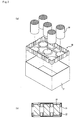
- Fig. 2 (a) is an exploded perspective view that explains an embodiment in which a honeycomb structured body is packaged with a packaging material 10 shown in Fig. 1 and further housed in a box member
- Fig. 2(b) is a cross-sectional view of the embodiment shown in Fig. 2(a).
- the packaging material 10, shown in Fig. 1 is a packaging material formed by molding a plastic sheet, and has a structure in which an installation portion 11 used for installing the end face neighborhood of an object to be packaged (honeycomb structured body) is formed on its upper face and a plurality of reinforcing portions (installation-face reinforcing portions) 12 are secured to a part of the area where no installation portion 11 is formed.
- the reinforcing portions 12 are secured in such a manner that, when each of them crosses the other reinforcing portion, the two portions are orthogonal to each other.
- a peripheral side face portion 14, formed by bending the plastic sheet upward, is formed on the peripheral portion of the packing member 10, and a plurality of grooves 15 are formed in the peripheral side face portion 14.
- the grooves 15 are also allowed to function as reinforcing portions (side face reinforcing portions).
- the installation portion 11 is formed in such a manner that the diameter (upper face diameter) of the upper face portion is made smaller than the diameter of the end face of the honeycomb structured body, and a side face 11a thereof is formed in a tapered shape with its diameter increasing toward the bottom face.
- the installation portion 11 is formed in a size that holds only one portion of the end face of the honeycomb structured body. In other words, the diameter of the upper face (indicated by L in the figure) of the installation portion 11 is made shorter than the diameter of the end face of the honeycomb structured body.
- Fig. 2 shows only the packaging material for the lower side of the honeycomb structured body, while Fig.
- FIG. 2(b) shows a state in which the upper and lower sides of the honeycomb structured body are packaged with the packaging materials.
- the upper face diameter (L in Fig. 1) and the bottom diameter (M in Fig. 1) of the installation portion 11 are respectively determined by the diameter of the end face of the honeycomb structured body, and the upper face diameter is preferably shorter than the diameter of the end face of the honeycomb structured body by about 2 to 40 mm, while the bottom diameter is preferably longer than the diameter of the end face of the honeycomb structured body by about 5 to 20 mm.
- the height of the installation portion 11 is about in a range from 1 to 10 mm when packaging a honeycomb structured body having a diameter of 145 mm and a length of 150 mm, for example.
- Irregularities may be formed on the installation portion 11.
- the irregularities having a surface roughness Ra of 0.1 ⁇ m or more are formed, the coefficient of friction between an object to be packaged and the installation portion can be increased so that displacement (slippage) of the object to be packaged can be prevented.
- the irregularities of 1 mm or more for example, grooves or the like
- a function of preventing deformation of the installation portion itself can be rendered thereto.
- reinforcing portions 12 are formed at an area of the installation face where the installation portions 11 are not formed.
- the formation of such reinforcing portions 12 makes it possible to prevent the packaging material 10 from being bent at the time of transportation or the like, and consequently to prevent the honeycomb structured body from being damaged.
- the reinforcing portions 12 are preferably formed in such a manner that, when each reinforcing portion 12 intersects with another reinforcing portion 12, those reinforcing portions are orthogonal to each other.
- the reinforcing portions 12 are formed so as to be orthogonal to each other, the strength of the packaging material is improved so that it is possible to surely prevent the packaging material from being bent.
- the installation portions and reinforcing portions are formed by processing the plastic sheet; that is, the entire portion is formed by the same material, and on the other hand, in the packaging material according to the first aspect of the present invention, a base portion (the portion other than the reinforcing portions) may be formed by processing the plastic sheet or the like, and the reinforcing portions may be formed using another material (see Figs. 3 and 4).
- the reinforcing portions may be formed by using a material that is comparatively more resistant against deformation than a material constituting the base portion, and specific examples of the material include: wood, metal, cardboard, styrofoam, and the like.
- Plastics may be used as the material for the reinforcing portions, and in this case, plasticmaterials of a kind that are highly resistant against deformation are preferably used.
- a peripheral side face portion 14 is formed on the peripheral portion of the packaging material 10.
- the contact area between the packaging material 10 and the inner face of the box member 21 is increased when the packaging material 10 is housed in the box member 21, thereby risk of displacement or bending of packaging material 10 inside the box member is decreased, and consequently damage is less likely to occur in the honeycomb structured body.
- grooves (side face reinforcing portions) 15, which function as reinforcing portion, are formed in the peripheral side face portion 14; thus, the formation of these grooves 15 further increases the strength of the peripheral side face portion 14, thereby further reducing the chance of displacement or bending of the packaging material.
- the grooves 15 of the peripheral side face portion 14 may be formed on demand.
- the grooves 15 are formed on the peripheral side face as the reinforcing portions; however, in place of the grooves 15, concave portions may be formed on the peripheral side face.
- reinforcing members made of wood, metal, plastics, cardboard, styrofoam or the like, may be secured to the positions in the peripheral side face corresponding to positions for the grooves and concave portions so that the reinforcing portions may be formed.
- the grooves refer to those grooves formed over the entire peripheral side face in the height direction (see Fig. 1)
- the concave portions refer to those concave portions formed only on part of the peripheral side face in the height direction (see Fig. 4).
- Fig. 12 (a) is a plan view that schematically shows another example of the packaging material in accordance with the first aspect of the present invention
- Fig. 12 (b) is a cross-sectional view taken along line A-A of the packaging material shown in Fig. 12 (a).
- the shape of the packaging material 110 shown in Fig. 12 is the same as that of the packaging material 10 shown in Fig. 1, except that the shape of the installation portion 111 is different; therefore, the description thereof is omitted.
- the packaging material in accordance with the first aspect of the present invention may have shapes, for example, as shown in Figs. 3 and 4.
- Figs. 3 (a) and 4 (a) are plan views that schematically show other examples of the packaging material in accordance with the first aspect of the present invention
- Figs. 3 (b) and 4 (b) are cross-sectional views taken along line A-A of the packaging materials shown in Figs. 3(a) and 4(a), respectively.
- the packaging material 30, shown in Fig. 3 is a packaging material formed by molding a plastic sheet, and has a structure in which an installation portion 31 used for installing the end face neighborhood of an object to be packaged (honeycomb structured body) is formed on its upper face. Moreover, a plurality of reinforcing portions (installation-face reinforcing portions) 32 are secured to a part of a face opposite to the face on which the installation portion 31 of a plastic sheet is formed.
- the reinforcing portions 32 are formed in such a manner that when each of them crosses the other reinforcing portion, the two portions are orthogonal to each other.
- the embodiment of the peripheral side face 34 of the packaging material 30 shown in Fig. 3 is the same as that of the packaging material 10 shown in Fig. 1, except that no grooves serving as reinforcing portions are formed thereon.
- the use of the packaging material 30 can also prevent displacement and bending of the packaging material at the time when a honeycomb structured body is packaged, housed in a box member, and transported or the like, and consequently prevents the honeycomb structured body from being, for example, damaged.
- the shape of the installation portion 31 is the same as that in the aforementioned packaging material 10; therefore, the description thereof is omitted.
- the packaging material 40 shown in Fig. 4 is a packaging material formed by molding a plastic sheet, and has a structure in which installation portions 41, each used for installing the end face neighborhood of an object to be packaged (honeycomb structured body), are formed on its upper face, and a plurality of reinforcing portions (installation-face reinforcing portions) 43 are secured to apart of an area where no installation portions 41 are formed, on the same face on which the installation portions 41 have been formed.
- a peripheral side face 44 formed by bending a plastic sheet upward, is formed on the peripheral portion of the packing member 40, and a plurality of concave portions 45 are formed on the peripheral side face 44.
- the concave portions 45 are also allowed to function as reinforcing portions.
- the embodiment of the packaging material 40 shown in Fig. 4 is the same as that of the packaging material 10 shown in Fig. 1, except that the shape of the reinforcing members 43 is different.
- the reinforcing portions 43 have a function of preventing the packaging material 30 from being bent, in the same manner as the reinforcing portions 12 formed in the packaging material 10.
- the use of the packaging material 40 can also prevent displacement and bending of the packaging material at the time when the honeycomb structured body is packaged, housed in the box member and transported, and consequently prevents the honeycomb structured body from being, for example, damaged.
- the shape of the installation portion 41 is the same as that of the aforementioned packaging material 10; therefore, the description thereof is omitted.
- each of the above-mentioned installation portions may be formed by forming a bottomed hole in the plate member.
- the installation area for the object to be packaged in the bottomed hole is desirably smaller than the opening area of the bottomed hole.
- the bottomed hole is preferably formed into a shape in which, when the object to be packaged is placed thereon, a gap is formedbetween the bottomed hole and the object to be packaged.
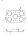
- Fig. 5 (a) is a perspective view that schematically shows another example of a packaging material in accordance with the first aspect of the present invention
- Fig. 5 (b) is a plan view showing the packaging material shown in Fig. 5 (a)
- Fig. 5(c) is a cross-sectional view taken along line A-A of the packaging material of Fig. 5(a).
- Fig. 6(a) is an exploded perspective view that explains an embodiment in which a honeycomb structured body is packaged with a packaging material 50 shown in Fig. 5 and further housed in a box member
- Fig. 6 (b) is a cross-sectional view of the embodiment shown in Fig. 6(a).
- the packaging material 50 shown in Fig. 5 is a packaging material formed by molding a plastic sheet, and has a structure in which bottomed holes 51, each used for installing the end face neighborhood of an object to be packaged (honeycomb structured body), are formed on its upper face, and a plurality of grooves (installation-face reinforcing portions) 52 are secured to a part of an area where no bottomed hole 51 is formed.
- the grooves 52 are secured in such a manner that when each of them crosses another groove, the two grooves are orthogonal to each other.
- a peripheral side face 54 formed by bending a plastic sheet downward, is formed on the peripheral portion of the packing member 50, and a plurality of grooves (side-face reinforcing portions) 55 are formed on the peripheral side face 54.
- the grooves 52 and 55 are also allowed to function as reinforcing portions.
- Each bottomed hole 51 is formed in such a manner that the diameter of the opening portion is larger than the diameter of the end face of a honeycomb structured body, and its side face 51a is formed into a tapered shape having the diameter decreasing toward the bottom face, and a raised bottom portion (installation portion) 56, which holds the end face of the honeycomb structured body, is formed on the bottom face.
- the raised bottom portion 56 is shaped into a size that supports only a part of the end face of the honeycomb structured body. In other words, the diameter of the upper face (indicated by L in the figure) of the raised bottom portion 56 is shorter than the diameter of the end face of the honeycomb structured body.
- the installation area for the honeycomb structured body in the bottomed hole 51 is smaller than the opening area of the bottomed hole 51, and in the packaging material 50 having such bottomed holes 51, only a part of the end face of the honeycomb structured body is made in contact with the installation portion so that damage is far less likely to occur in the honeycomb structured body at the time of a transporting process or the like.
- the end face neighborhood of the honeycomb structured body is housed in each bottomed hole 51, and the packaging material 10 in which the honeycomb structured body 20 has been packaged is housed in the box member 21.
- the packaging material 10 in which the honeycomb structured body 20 has been packaged is housed in the box member 21.
- the box member 21 normally, not only the lower side of the honeycomb structured body 20, but also the upper side thereof is packaged with the packaging material. In other words, the end face neighborhood of the honeycomb structured body 20 on the upper side is held by the packaging material 50 in its upside down state.
- the raised bottom portion 56 is formed on the bottom face of each bottomed hole 51. As shown in Fig. 6, at the time of a transporting process or the like of the packaging material 50 and the honeycomb structured body 20, both housed in the box member 21, the formation of such a raised bottom portion 56 makes it possible to prevent the honeycomb structured body from being damaged due to impact from below.
- the opening diameter and the bottom diameter of the bottomed hole 51 are respectively determined according to the diameter of the end face of the honeycomb structured body, and the opening diameter is preferablymade longer than the diameter of the end face of the honeycomb structured body by about 5 mm to 20 mm, while the bottom diameter is preferably made shorter than the diameter of the end face of the honeycomb structured body by about 2 mm to 10 mm.
- the depth of the bottomed hole 51 and the raised height of the raised bottom portion 56 are set in a range from 20 mm to 50 mm and in a range from 1 to 10 mm, respectively, in the case where, for example, a honeycomb structured body having ⁇ 145 mm and a length of 150 mm is packaged.
- the upper face diameter (L, in Fig. 5) of the raised bottom portion 56 may be applicable as long as it is shorter than the diameter of the end face of the honeycomb structured body, and by ordinary, it is desirably shorter by 5 mm to 40 mm.
- Grooves 52 are formed in an area of the packaging material 50 where no bottomed hole 51 is formed.
- the formation of these grooves 52 makes it possible to prevent the packaging material 50 from being bent at the time of a transporting process or the like, and consequently to prevent the honeycomb structured body from being damaged.
- the grooves 52 are preferably formed in such a manner that when each of them crosses another groove, the two grooves are orthogonal to each other.
- the grooves 52 are formed so as to be orthogonal to each other in this manner, the strength of the packaging material is improved so that it ispossible to certainly prevent the packaging material from being bent.
- a peripheral side face 54 is formed on the peripheral portion of the packing member 50.
- the contact area between the packaging material 50 and the inner face of the box member 21 is increased when the packaging material 50 is housed in the box member 21, thereby making it possible to prevent the packaging material 50 from being displaced or bent inside the box member, and consequently damage becomes less likely to occur in the honeycomb structured body.
- grooves 55 which function as reinforcing portions, are formed on the peripheral side face 54, and the formation of these grooves 55 further increases the strength of the peripheral side face 54, thereby further preventing the packaging material from being displaced and bent.
- grooves 52 which function as reinforcing portions, are formed on the upper face thereof by processing a plastic sheet; while, reinforcing members, made of wood, metal, plastics, cardboard, styrofoam or the like, may be secured to positions on the upper face or the lower face of the plastic sheet corresponding to the positions for these grooves so that the reinforcing portions may be formed.
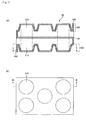
- the packaging material in accordance with the first aspect of the present invention may have a shape as shown in Figs. 7 and 8.
- Figs. 7 (a) and 8 (a) are plan views that schematically show one example of another packaging material in accordance with the first aspect of the present invention
- Figs. 7(b) and 8(b) are cross-sectional views taken along line A-A of the packaging materials Figs. 7(a) and 8(a), respectively.
- the packaging material 70 shown in Fig. 7, is a packaging material formed by molding a plastic sheet, and has a structure in which bottomed holes 71, each used for installing the end face neighborhood of a honeycomb structured body, are formed on its upper face and a plurality of grooves (installation-face reinforcing portions) 72 are formed on a part of the area where no bottomed hole 71 is formed.
- the grooves 72 are formed in such a manner that when each of them crosses another groove, the two grooves are made orthogonal to each other.
- a peripheral side face 74 formed by bending a plastic sheet downward, is formed on the peripheral portion of the packing member 70.
- the embodiment of the packaging material 70 shown in Fig. 7 is the same as that of the packaging material 50 shown in Fig. 5, except that no grooves (side-face reinforcing portions) are formed on the peripheral side face 74.
- the use of the packaging material 70 also prevents displacement and bending of the packaging material at the time when the honeycomb structured body, packaged and housed in the box member, is transported, or the like, and consequently can prevent the honeycomb structured body from being damaged. In this manner, even in the case where the reinforcing portions are formed only on the upper face of the plastic sheet, the same effects as those of the first aspect of the present invention can be obtained.
- the packaging material 80 is a packaging material formed by molding a plastic sheet, and has a structure in which bottomed holes 81, each used for installing the end face neighborhood of an object to be packaged (honeycomb structured body), are formed on its upper face and a plurality of grooves (installation-face reinforcing portions) 83 are formed on a part of an area where no bottomed hole 81 is formed.
- a peripheral side face 84 formed by bending a plastic sheet downward, is formed on the peripheral portion of the packing member 80, and a plurality of grooves (side-face reinforcing portions) 85, which serve as reinforcing portions, are further formed on the peripheral side face 84.
- the shape of the packaging material 80 shown in Fig. 8 is the same as that of the packaging material 50 shown in Fig. 5, except that in place of the grooves, concave portions 83 are formed on the upper face thereof. In the same manner as the grooves 52 formed in the packaging material 50, the concave portions 83 have a function for preventing the packaging material 80 from being bent.
- the use of the packaging material 80 also prevents displacement and bending of the packaging material at the time when the honeycomb structured body, packaged and housed in the box member, is transported, or the like, and consequently can prevent the honeycomb structured body from being, for example, damaged.
- the grooves and the concave portions serving as the installation face reinforcing portions which are formed in an area that bears no bottomed holes, are allowed to have virtually the same functions and structures; however in the present specification, those having the end portion extending to the side face of each bottomed hole are referred to as groove, and those formed in a completely independent manner from each bottomed hole is referred to as the concave portion.
- both of the groove and the concave portion may be formed on each of the installation face and the peripheral side face of a signal packaging material.
- the packaging material in accordance with the first aspect of the present invention may be the embodiment as shown in Fig. 9.
- Fig. 9 (a) is a plan view that schematically shows another example of the packaging material in accordance with the first aspect of the present invention
- Fig. 9(b) is a cross-sectional view taken along line A-A of the packaging material of Fig. 9(a).
- bottomed holes 91 used for installing the end face neighborhood of an object to be packaged are formed on its upper face and a plurality of concave portions (installation-face reinforcing portions) 93 serving as reinforcing portions are formed on a part of the area where no bottomed holes 91 are formed.
- a peripheral side face 94, formed by bending a plastic sheet downward, is formed on the peripheral portion of the packing member 90, and a plurality of grooves 95 serving as reinforcing portions are formed on the peripheral side face 94.
- Each bottomed hole 91 is formed in such a manner that the opening diameter is made greater than the diameter of the end face of a honeycomb structured body, and a side face 91a thereof is formed in a tapered shape with the diameter decreasing toward the bottom face.
- the embodiment of the packaging material 90 shown in Fig. 9 is the same as that of the packaging material 80 shown in Fig. 8, except that no raised portion is formed on the bottom face of each bottomed hole 91.
- the packaging material of the present invention even in the case where no raised portion is formed in each bottomed hole, as long as concave portions are formed on both of the area of the upper face where no bottomed holes are formed and the peripheral side face, the above-mentioned effects, that is, the effects of preventing the occurrence of displacement and bending in the packaging material, for example, at the time when the honeycomb structured body, packaged and housed in the box member, is transported, and preventing the honeycomb structured body from being damaged, and the like, can be obtained.
- the packaging material in accordance with the first aspect of the present invention may be an embodiment as shown in Fig. 13.
- Fig. 13 (a) is a plan view that schematically shows another example of the packaging material in accordance with the first aspect of the present invention
- Fig. 13(b) is a cross-sectional view taken along line A-A of the packaging material of Fig. 13(a).
- a packaging material 120 shown in Fig. 13 is provided with bottomed holes 121 that serve as installation portions for honeycomb structural bodies.
- Each of the bottomed holes 121 is formed in such a manner that the diameter of its opening portion is made larger than the diameter of the end face of the honeycomb structured body, and the side face 121a thereof is formed into a tapered shape with the diameter decreasing toward the bottom face, and a raised bottom portion (installation portion) 126, which holds the end face of the honeycomb structured body, is formed on the bottom face.
- the raised bottom portion 126 is formed with such a size that only one portion of the end face of the honeycomb structured body is supported.
- the raised bottom portion 126 has a shape of a truncated cone shape in which a concave portion 126b is formed in the center thereof.
- the installation portion having this structure since the contact area between the end face of the honeycomb structured body and the installation portion is made smaller, the occurrence of damage and the like in the honeycomb structured body tends to be reduced.
- the shape of the packaging material 120 shown in Fig. 13 is the same as that of the packaging material 50 shown in Fig. 5, except that the shape of the raised bottom portion 126 is different; therefore, the description thereof is omitted.
- the packaging material in accordance with the first aspect of the present invention may be the embodiment as shown in Fig. 14.
- Fig. 14 (a) is a plan view that schematically shows another example of the packaging material in accordance with the first aspect of the present invention
- Fig. 14(b) is a cross-sectional view taken along line A-A of the packaging material of Fig. 14(a).
- Each of bottomed holes 131 is formed in such a manner that the diameter of its opening portion is made larger than the diameter of the end face of the honeycomb structured body, and a side face 131a thereof is formed into a tapered shape with the diameter decreasing toward the bottom face, and a raised bottom portion (installation portion) 136, which holds the end face of the honeycomb structured body, is formed on the bottom face.
- the raised bottom portion 136 is formed in a size that supports only a part of the end face of the honeycomb structured body.
- the installation portion having this structure since the contact area between the end face of the honeycomb structured body and the installation portion is made smaller, the occurrence of damages and the like to the honeycomb structured body tends to be reduced.
- the shape of the packaging material 130 shown in Fig. 14 is the same as that of the packaging material 50 shown in Fig. 5, except that the shape of the bottomed hole 131 is different; therefore, the description thereof is omitted.
- the reinforcing portion is desirably formed by installing grooves and/or concave portions in the plate member.
- the structure in which the grooves and/or concave portions that function as reinforcing portions are formed on the plate member in this manner makes the manufacturing process easier and is economically advantageous, in comparison with the structure of a packaging material (for example, see Fig. 3, etc.) in which a reinforcing portion, made of a material different from the plate member, is manufactured and secured thereto.
- the installation portion is desirably constructed by forming a bottomed hole in the plate member.
- the installation portion is constructed by forming a bottomed hole, it becomes possible to more positively package the packaged honeycomb structured body.
- the installation area for an object to be packaged in the bottomed hole is preferably made smaller than the opening area of the bottomed hole.
- the bottomed hole is formed into this shape, the occurrence of damage, such as breakage and cracks , on the end portion and side face of the honeycomb structured body tends to be reduced.
- the bottomed hole is preferably formed into such a shape that, when an object to be packaged is installed, a gap is formed between the bottomed hole and the object to be packaged.
- the bottomed hole is formed into this shape, the occurrence of damages, such as breakage and cracks, on the end portion and side face of the honeycomb structured body tends to be reduced.
- the bottomed hole used for housing the end face neighborhood of the honeycomb structured body is not necessarily formed into a tapered shape on its side face as shown in Fig. 5 and the like, and the opening and the bottom face may have the same diameter.
- the packaging material is made of a plate member, and a plastic sheet may be used as the plate member.
- a plastic sheet may be used as the plate member.
- the plastic material include polypropylene, polyethylene, polyethylene terephthalate and the like.
- the material for the plate member is not limited to plastics, and the examples thereof include cardboard, styrofoam, and the like.
- the packaging material is constituted by a plastic sheet in its entire portion including reinforcing portions
- it can be manufactured by using a conventionally known molding method for a plastic material, such as a vacuum molding method and an injection molding method, and while in the case where the reinforcing portions are formed by using another material such as metal and wood, a method in which the base portion (portions other than the reinforcing portions) of the packaging material is manufactured by the above-mentioned method, and the reinforcing portions are secured thereto by using a bonding agent or the like, may be used.
- the packaging material in accordance with the second aspect of the present invention is a packaging material comprising a plate member, which packages an object to be packaged by sandwiching the object, and the plate member is provided with an installation portion for the obj ect to be packaged comprising a bottomed hole, and the installation area for the object to be packaged in the bottomed hole is made smaller than the opening area of the bottomed hole.
- example thereof include a shape in which no reinforcing portions are formed, and an installation portion that is the same as in the packaging materials shown in Figs. 5, 7 to 9, 13 and 14 is formed, and the like.
- this shape the end face neighborhood of the object to be packaged can be easily inserted into the bottomed hole so that the object to be packaged can be easily packaged.
- the packagingmaterial in accordance with the second aspect of the present invention is made of a plate member, and specific examples of the plate member include those plate members similar to the plate members constituting the packaging materials in accordance with the first aspect of the present invention.
- the packaging material in accordance with the second aspect of the present invention can be manufactured by using a conventionally known molding method for a plastic material, such as a vacuum molding method and an injection molding method, and the like.
- the packaging material in accordance with the third aspect of the present invention is a packaging material comprising a plate member, which packages an object to be packaged by sandwiching the object, and the plate member is provided with installation portions for objects to be packaged comprising a bottomed hole, and the bottomed hole has such a shape that, when an obj ect to be packaged is placed therein, a gap is formedbetween the bottomed hole and the object to be packaged.
- example thereof include a shape in which no reinforcing portions are formed, and an installation portion that is the same as those packaging materials shown in Figs. 5, 7, 8, 13 and 14 is formed, and the like.
- the end face particularly, corner portions of the end face
- damage is far less likely to happen.
- the packaging material in accordance with the third aspect of the present invention is made of a plate member, and specific examples of the plate member include those plate members similar to the plate member constituting the packaging materials in accordance with the first aspect of the present invention.
- the packaging material in accordance with the third aspect of the present invention can be manufactured by using a conventionally known molding method for a plastic material, such as a vacuummoldingmethod and an inj ectionmolding method, and the like.
- the packaging material of the fourth aspect of the present invention is a packaging material, which packages an object to be packaged by sandwiching the object, and comprises:
- Fig. 10 (a) is a vertical cross-sectional view that shows a packaging material in accordance with the fourth aspect of the present invention
- Fig. 10 (b) is a cross-sectional view taken along line A-A of Fig. 10(a)
- Fig. 10(c) is a cross-sectional view taken along line B-B of Fig. 10(a)
- Fig. 10(d) is a developed view of the packaging material shown in Fig. 10(a).
- Fig. 10 (a) is a vertical cross-sectional view taken along line C-C of each of Fig. 10(b) and Fig. 10(c).
- ⁇ to ⁇ in Fig. 10(a) respectively correspond to ⁇ to ⁇ in those of each Figs. 10(b) to 10(d).
- a packaging material 100 is a packaging material formed by processing a sheet of cardboard, and comprises an installation member 102 in which an installation portion 101 for placing the end face neighborhood of the end faces of an obj ect to be packaged (honeycomb structured body) is formed, a holding member 104 in which a through hole 103 is formed, and a protective member 105, and the above members are configured into an integral unit through connecting portions 107A and 107B.
- a notched portion 106 is formed on the periphery of the installation unit 101 so that the entire bottom face of the object to be packaged is prevented from coming into contact with the protective member and the installation member.
- the notched portion 106 may be formed on demand.
- a cardboard having a large area as shown in Fig. 10 (d) is used, and first, two side portions are bent downward along lines extending from starting points ⁇ and ⁇ , and further bent inward along lines extending from starting points ⁇ and ⁇ so that the installation member 102 and the protective member 105 are superposed one on the other. Lastly, the two side portions respectively sandwiching the lines extending from the starting points ⁇ and ⁇ , as well as the lines extending from the starting points ⁇ and ⁇ , are folded inward so as to make a 90° angle each so that the installation member 102 and the protective member 105 are completely overlapped with each other.
- the installation member 102 is arranged to be placed on the protective member 105.
- a packaging material 100 which has a rectangular parallelepiped shape in the outer appearance and has a cross section shown in Fig. 1 (a) , taken along line C-C of each of Figs. 10(b) and 10(c), can be manufactured.
- the end portion of a honeycomb structured body (indicated by a dashed line in the Figure) is placed on the installation portion 101 of the installationmember 102, with the honeycomb structured body being allowed to penetrate the through hole 103 formed in the holding member 104; accordingly, the honeycomb structured body is held.
- the protective member 105 is formed, the strength of the packaging material can be improved. Therefore, no displacement or the like are caused in the honeycomb structured body, and thus the obj ect to be packaged can be positively held.
- the packaging material 100 has such a superior strength that it can prevent a packaging material from being bent at the time of transporting the packaging material housed in a box member, and consequently, no damage and the like is caused to the honeycomb structured body.
- peripheral side faces 107A and 107B are formed between the installation member 102 and the holding member 104, and between the holding member 104 and the protective member 105, respectively.
- the formation of the peripheral side faces 107A and 107B makes it possible to increase the contact area between the packaging material 100 and the inner face of a box member when the packaging material 100 is housed in the box member, and consequently the risk of displacement or bending of the packaging material 100 inside the box member is reduced, thereby further preventing the honeycomb structured body from being damaged.
- concave portions and through holes may be formed on the peripheral side faces 107A and 107B, if necessary. These arrangements contribute to weight saving and an easy bending upon manufacturing.
- a concave portion is preferably formed on the side face 107B to achieve an easy fitting.
- the material for the packaging material in accordance with the fourth aspect of the present invention is not limited to cardboard, and plastic materials, styrofoam, and the like may be used in the same manner as the packaging material in accordance with the first aspect of the present invention.
- the packaging material in accordance with the fourth aspect of the present invention may be manufactured by processing, for example, a cardboard through a conventionally known method.
- the packaging material in accordance with the fifth aspect of the present invention which is used for packaging a pillar-shaped object to be packaged, comprises:
- Fig. 11 (a) is a vertical cross-sectional view that shows a packaging material in accordance with the fifth aspect of the present invention
- Fig. 11 (b) is a horizontal cross-sectional view of the packaging material in accordance with the fifth aspect of the present invention
- Fig. 11 (a) is a vertical cross-sectional view taken along line B-B of Fig. 11(b)
- Fig. 11(b) is a horizontal cross-sectional view taken along line A-A of Fig. 11(a).
- a packaging material 60 is a packaging material formed by processing a sheet of cardboard, and has a structure in which a bottom holding member 62A in which a bottomed hole 61A that houses an end face neighborhood of one of the end faces of the object to be packaged (honeycomb structured body) is formed, and an upper holding member 62B in which a bottomed hole 61B that houses the end face neighborhood of the other end face of the honeycomb structured body is formed are configured into an integral unit through an intermediate holding member 63.
- the bottomed hole 61A and the bottomed hole 61B are formed at such positions as to be overlapped with each other in the plan view.
- the through hole that allows the penetration of the honeycomb structured body is formed in the intermediate holding member 63 and the through hole is formed in such a position that the bottomed hole 61A and the bottomed hole 61B are overlapped with each other in the plan view.
- the end portions of a honeycomb structured body are respectively held by the bottomed hole 61A and the bottomed hole 61B, and by allowing the honeycomb structured body to penetrate the through hole formed in the intermediate holding member 63, the honeycomb structured body is further supported.
- the honeycomb structured body can be reliably supported without displacement and the like.
- the packaging material 60 has a structure in which the bottom holding member 62A, the upper holding member 62B and the intermediate holding member 63 are configured into an integral unit, therefore has such a superior strength that it can prevent a packaging material from being bent at the time of transporting the packaging material housed in a box member, and consequently, no damage and the like is caused to the honeycomb structured body.
- peripheral side faces 64A and 64B are respectively formed on the bottom holding member at the side opposite to the side that is integral with the intermediate holding member, and on the upper holding member at the side opposite to the side that is integral with the intermediate holding member.
- the material for the packaging material in accordance with the fifth aspect of the present invention is not limited to cardboard, and plastic materials, styrofoam, and the like may be used in the same manner as the packaging material in accordance with the first aspect of the present invention.
- the packagingmaterial in accordance with the fourth aspect of the present invention may be manufactured by processing, for example, a cardboard through a conventionally known method.
- Methods of transporting a honeycomb structured body in accordance with the sixth to tenth aspects of the present invention are methods of transporting a honeycomb structured body using the packaging materials of the first to fifth aspects of the present invention, respectively, and since the transporting method has been explained above in the present specification, the specific explanation thereof is omitted.
- honeycomb structured body examples thereof include a filter used for capturing particulates in the exhaust gas, a honeycomb structured body used as a catalyst supporting carrier for converting the exhaust gas, and the like.
- Apackaging material having the same shape as the packaging material 10 of Fig. 1 was manufactured.
- a polypropylene sheet of 0.5 mm in thickness was used as a plate member, and each of reinforcing portions (installation face reinforcing units) 12 was formed by securing a plywood plate of 20 mm in width and 1 mm in thickness.
- each of the installation portions 11 had a size of 130 mm in the upper face diameter ⁇ 150 mm in the bottom face diameter
- the groove (side face reinforcing portion) 15 had a size of 20 m in width ⁇ 5 mm in depth
- the external size was set to 560 mm in width ⁇ 380 mm in length ⁇ 50 mm in height.
- the polypropylene sheet was processed so that the surface roughness of the upper face of the installation portion 11 was set to 0.1 mm.
- a packaging material was manufactured in the same manner as Example 1, except that grooves 15 were not formed in the peripheral side face portion 14, and a plywood plate (Example 2) of 20 mm in width and 1 mm in thickness, or an aluminum plate (Example 3) of 20 mm in width and 0.5 mm in thickness was secured onto a position corresponding to each of the grooves as a side face reinforcing portion.
- a packaging material was manufactured in the same manner as Example 1, except that, in place of each of the grooves on the peripheral side face, a concave portion (see 45 in Fig. 4) having a size of 20 mm in width ⁇ 5 mm in depth ⁇ 30 mm in height was formed as a side face reinforcing portion.
- a packaging material was manufactured in the same manner as in the respective Examples 1 to 4, except that the reinforcing portion 12 was formed by using an aluminum plate of 2 mm in width and 0.5 mm in thickness in place of the plywood plate.
- a packaging material was manufactured in the same manner as in the respective Examples 1 to 4, except that the reinforcing portion 12 was formed not by securing a plywood plate, but by molding the polypropylene sheet.
- the reinforcing portion had a size of 20 mm in width ⁇ 5 mm in height.
- a packaging material was manufactured in the same manner as in the respective Examples 9 to 12, except that the shape of each installation face reinforcing portion was changed to a reinforcing portion 43 shown in Fig. 4 from a reinforcing portion 12 shown in Fig. 1.
- the reinforcing portion had a size of 20 mm in width ⁇ 150 mm in length ⁇ 5 mm in height or 20 mm in width ⁇ 50 mm in length ⁇ 5 mm in height.
- a packaging material was manufactured in the same manner as in the respective Examples 1, 5, 9 and 13, except that no side face reinforcing portions were formed.
- a packaging material was manufactured in the same manner as in the respective Examples 1 to 4, except that no installation face reinforcing portions were formed.
- Apackagingmaterial having the same shape as the packaging material 110 of Fig. 12 was manufactured.
- a polypropylene sheet of 0.5 mm in thickness was used as a plate member, and each of reinforcing portions (installation face reinforcing units) 112 was formed by securing a plywood plate of 20 mm in width and 1 mm in thickness.
- each of the installation portions 111 had a size of 130 mm in the upper face outer diameter L 1 , 120 mm in the upper face inner diameter L 2 , 150 mm in the bottom face outer diameter M 1 and 100 mm in the bottom face inner diameter M 2
- each of grooves (side face reinforcing portions) 115 of the peripheral side face 114 had a size of 20 m in width ⁇ 5 mm in depth, and the external size was set to 560 mm in width ⁇ 380 mm in depth ⁇ 50 mm in height.
- the polypropylene sheet was processed so that the surface roughness of the upper face of the installation portion 111 was set to 1 mm.
- a packaging material was manufactured in the same manner as Example 17, except that grooves 115 were not formed on the peripheral side face 114, and a plywood plate (Example 18) of 20 mm in width and 1 mm in thickness, or an aluminum plate (Example 19) of 20 mm in width and 0.5 mm in thickness was secured as a side face reinforcing portion onto a position corresponding to each of the grooves.
- a packaging material was manufactured in the same manner as Example 17, except that, in place of each of the grooves on the peripheral side face, a concave portion (see 45 in Fig. 4) having a size of 20 mm in width ⁇ 5 mm in depth ⁇ 30 mm in height was formed as a side face reinforcing portion.
- a packaging material was were manufactured in the same manner as in the respective Examples 17 to 20, except that the reinforcing portion 112 was formed by using an aluminum plate of 2 mm in width and 0.5 mm in thickness in place of the plywood plate.
- a packaging material was manufactured in the same manner as in the respective Examples 17 to 20, except that the reinforcing portion 112 was formed not by securing a plywood plate, but by molding the polypropylene sheet.
- the reinforcing portion had a size of 20 mm in width ⁇ 5 mm in height.
- a packaging material was manufactured in the same manner as in the respective Examples 17 to 20, except that the shape of each reinforcing portion to be formed on the same face as the face bearing the installation portion was changed to a reinforcing portion 43 shown in Fig. 4 from a reinforcing portion 112 shown in Fig. 12.
- the reinforcing portion had a size of 20 mm in width ⁇ 150 mm in length ⁇ 5 mm in height or 20 mm in width ⁇ 50 mm in length ⁇ 5 mm in height.
- a packaging material was manufactured in the same manner as in the respective Examples 17, 21, 25 and 29, except that no side face reinforcing portions were formed.
- a packaging material was manufactured in the same manner as in the respective Examples 17 to 20, except that no installation face reinforcing portions were formed.
- Apackaging material having the same shape as the packaging material 50 shown in Fig. 5 was manufactured.
- a polypropylene sheet of 0.5 mm in thickness was used as a plate member, and each of reinforcing portions (grooves) 52 had a size of 20 mm in width and 5 mm in depth.
- the bottomed hole 51 had a size of 155 mm in the opening diameter, 150 mm in the bottom face diameter and 130 mm in the upper face diameter of the raised bottom portion 56, and each groove (side-face reinforcing portion) 55 of the peripheral side face 54 had a size of 20 m in width ⁇ 5 mm in depth and an external size of 560 mm in width ⁇ 380 mm in depth ⁇ 50 mm in height.
- the polypropylene sheet was processed so that the surface roughness of the upper face of the raised bottom portion 56 was set to 0.1 mm.
- a packaging material was manufactured in the same manner as Example 33, except that grooves 55 were not formed on the peripheral side face 54, and a plywood plate (Example 34) of 20 mm in width and 1 mm in thickness or an aluminum plate (Example 35) of 20 mm in width and 0.5 mm in thickness was secured onto a position corresponding to each of the grooves as a side face reinforcing portion.
- a packaging material was manufactured in the same manner as Example 33, except that, in place of each of the grooves on the peripheral side face, a concave portion (see 45 in Fig. 4) having a size of 20 mm in width ⁇ 5 mm in depth ⁇ 30 mm in height was formed as a side face reinforcing portion.
- a packaging material was manufactured in the same manner as in the respective Examples 33 to 36, except that grooves 52 were not formed, and a plywood plate of 2 mm in width and 1 mm in thickness was secured as an installation face reinforcing portion onto a position corresponding to each of the grooves.
- a packaging material was manufactured in the same manner as in the respective Examples 33 to 36, except that grooves 52 were not formed, and an aluminum plate of 2 mm in width and 0.5 mm in thickness was secured onto a position corresponding to each of the grooves as an installation face reinforcing portion.
- a packaging material was manufactured in the same manner as in the respective Examples 33 to 36, except that the shape of each installation face reinforcing portion was changed to a concave portion 83 shown in Fig. 8 from the groove 52 shown in Fig. 5.
- the reinforcing portion had a size of 20 mm in width ⁇ 150 mm in length ⁇ 5 mm in depth or 20 mm in width ⁇ 50 mm in length ⁇ 5 mm in depth.
- a packaging material was manufactured in the same manner as in the respective Examples 33, 37, 41 and 45, except that no side face reinforcing portions were formed.
- a packaging material was manufactured in the same manner as in the respective Examples 33 to 36, except that no installation face reinforcing portions were formed.
- Apackaging material having the same shape as the packaging material 120 of Fig. 13 was manufactured.
- a polypropylene sheet of 0.5 mm in thickness was used as a plate member, and each of grooves (installation face reinforcing units) 122 had a size of 20 mm in width and 5 mm in depth.
- the bottomed hole 121 had a size of 155 mm in the opening diameter and 150 mm in the bottom face diameter
- the raised bottom portion 126 had a size of 130 mm in outer diameter and 120 mm in inner diameter
- each groove (side-face reinforcing portion) 125 of the peripheral side face 124 had a size of 20 m in width ⁇ 5 mm in depth and an external size of 560 mm in width ⁇ 380 mm in depth ⁇ 50 mm in height.
- the polypropylene sheet was processed so that the surface roughness of the upper face of the raised bottom portion 126 was set to 1 mm.
- a packaging material was manufactured in the same manner as Example 49, except that grooves 125 were not formed on the peripheral side face 124, and a plywood plate (Example 50) of 20 mm in width and 1 mm in thickness or an aluminum plate (Example 51) of 20 mm in width and 0.5 mm in thickness was secured onto a position corresponding to each of the grooves as a side face reinforcing portion.
- a packaging material was manufactured in the same manner as Example 49, except that, in place of each of the grooves on the peripheral side face, a concave portion (see 45 in Fig. 4) having a size of 20 mm in width ⁇ 5 mm in depth ⁇ 30 mm in height was formed as a side face reinforcing portion.
- a packaging material was manufactured in the same manner as in the respective Examples 49 to 52, except that grooves 122 were not formed, and a plywood plate of 2 mm in width and 1 mm in thickness was secured onto a position corresponding to each of the grooves as an installation face reinforcing portion.
- a packaging material was manufactured in the same manner as in the respective Examples 49 to 52, except that grooves 122 were not formed, and an aluminum plate of 2 mm in width and 0.5 mm in thickness was secured onto a position corresponding to each of the grooves as an installation face reinforcing portion.
- a packaging material was manufactured in the same manner as in the respective Examples 49 to 52, except that the shape of each installation face reinforcing portion was changed to a concave portion 83 shown in Fig. 8 from the groove 122 shown in Fig. 13.
- the reinforcing portion had a size of 20 mm in width ⁇ 150 mm in length ⁇ 5 mm in height, or 20 mm in width ⁇ 50 mm in length ⁇ 5 mm in depth.
- a packaging material was manufactured in the same manner as in the respective Examples 49, 53, 57 and 61, except that no side face reinforcing portions were formed.
- a packaging material was manufactured in the same manner as in the respective Examples 49 to 52, except that no installation face reinforcing portions were formed.
- Apackagingmaterial having the same shape as the packaging material 130 of Fig. 14 was manufactured.
- a polypropylene sheet of 0.5 mm in thickness was used as a plate member, and each of grooves (installation face reinforcing units) 132 had a size of 20 mm in width and 5 mm in depth.
- the bottomed hole 131 had a size of 155 mm in the opening diameter and 165 mm in the bottom face diameter
- the raised bottom portion 136 had a size of 130 mm in outer diameter
- each groove (side-face reinforcing portion) 135 of the peripheral side face 134 had a size of 20 m in width ⁇ 5 mm in depth and an external size of 560 mm in width ⁇ 380 mm in depth ⁇ 50 mm in height.
- the polypropylene sheet was processed so that the surface roughness of the upper face of the raised bottom portion 136 was set to 1 mm.
- a packaging material was manufactured in the same manner as Example 65, except that grooves 135 were not formed on the peripheral side face 134, and a plywood plate (Example 66) of 20 mm in width and 1 mm in thickness or an aluminum plate (Example 67) of 20 mm in width and 0.5 mm in thickness was secured onto a position corresponding to each of the grooves as a side face reinforcing portion.
- a packaging material was manufactured in the same manner as Example 65, except that, in place of each of the grooves on the peripheral side face, a concave portion (see 45 in Fig. 4) having a size of 20 mm in width ⁇ 5 mm in depth ⁇ 30 mm in height was formed as a side face reinforcing portion.
- a packaging material was manufactured in the same manner as in the respective Examples 65 to 68, except that grooves 132 were not formed, and a plywood plate of 2 mm in width and 1 mm in thickness was secured onto a position corresponding to each of the grooves as an installation face reinforcing portion.
- a packaging material was manufactured in the same manner as in the respective Examples 65 to 68, except that grooves 132 were not formed, and an aluminum plate of 2 mm in width and 0.5 mm in thickness was secured onto a position corresponding to each of the grooves as an installation face reinforcing portion.
- a packaging material was manufactured in the same manner as in the respective Examples 65 to 68, except that the shape of each installation face reinforcing portion was changed to a concave portion 83 shown in Fig. 8 from the groove 132 shown in Fig. 14.
- the reinforcing portion had a size of 20 mm in width ⁇ 150 mm in length ⁇ 5 mm in depth, or 20 mm in width ⁇ 50 mm in length ⁇ 5 mm in depth.
- a packaging material was manufactured in the same manner as in the respective Examples 65, 69, 73 and 77, except that no side face reinforcing portions were formed.
- a packaging material was manufactured in the same manner as in the respective Examples 65 to 68, except that no installation face reinforcing portions were formed.
- a packaging material 60 having a shape shown in Fig. 11 was manufactured by processing a cardboard having a thickness of 5 mm.
- the packaging material 60 manufactured in the present example had an external size of 530 ⁇ 340 mm, and each of bottomed holes 61A and 61B had an opening diameter of 148 mm.
- a packaging material 100 having a shape shown in Fig. 10 was manufactured by processing a cardboard having a thickness of 5 mm.
- the packaging material 100 manufactured in the present example had an external size of 530 ⁇ 340 mm ⁇ 50, and each of through holes 103 had an opening diameter of 148 mm.
Landscapes
- Engineering & Computer Science (AREA)
- Mechanical Engineering (AREA)
- Buffer Packaging (AREA)
- Packages (AREA)
- Packaging Frangible Articles (AREA)
- Container Filling Or Packaging Operations (AREA)
- Basic Packing Technique (AREA)
- Supplying Of Containers To The Packaging Station (AREA)
Abstract
Description
- The present invention relates to a packaging material, in particular, a packaging material to be used upon transporting a honeycomb structured body comprising porous ceramics and the like, and a method of transporting a honeycomb structured body using the packaging material.
- In recent years, particulates such as soot contained in exhaust gases that are discharged from internal combustion engines of vehicles, such as buses and trucks, and construction machines, have raised serious problems as contaminants harmful to the environment and the human body.
Various ceramic filters using honeycomb structural bodies made from porous ceramics, which collect particulates in exhaust gases to purify the exhaust gases, have been proposed. - More specifically, those filters made fromporous ceramics such as silicon carbide and cordierite have been proposed, and in particular, the honeycomb structural bodies made from silicon carbide exert superior advantages in thermal conductivity, heat resistance, mechanical characteristics, chemical resistance and the like.
- The honeycomb structured body of this kind is mainly composed of a porous ceramic material that is a fragile material, and thus it can be damaged due to external impact applied upon transportation or the like.
In order to avoid such damage to the honeycomb structured body, various packaging materials and holding plates for honeycomb structural bodies have been proposed so as to protect the honeycomb structured body from external impact or the like (for example, seePatent Document 1 and Patent Document 2). -
- Patent Document 1:
JP-A 2003-112771 - Patent Document 2:
JP-A 2004-42964 - However, in the case of the conventionally known packaging materials for supporting honeycomb structural bodies, holding plates for honeycomb structural bodies and the like, upon transporting honeycomb structural bodies, distortion tends to occur in the packaging material and the holding plate due to their virtually flat shape, causing the deformation of the packaging material and the holding plate. As a result, positional displacement of honeycomb structural bodies tend to occur, and this leads to mutual contacts among the honeycomb structural bodies, or contacts between the honeycomb structural body and the packaging material, and consequently there is a chance of damage in the honeycomb structural bodies.
Therefore, there have been strong demands for packaging materials which can prevent damage to the honeycomb structural bodies and the like. - In order to solve the above-mentioned problems, the inventors of the present invention have studied hard, and have newly found a packaging material that can prevent positional displacement and bending, and a method of transporting a honeycomb structured body in which the packaging material is used, thereby completing the present invention.
In other words, in accordance with a first aspect of the present invention, a packaging material which comprises a plate member, packages an object to be packaged by sandwiching the object, and the plate member is provided with an installation portion for the object to be packaged and provided as well with a reinforcing portion. - In the packaging material in accordance with the first aspect of the present invention, the reinforcing portion is preferably formed by forming a groove and/or a concave portion in the plate member.
Moreover, the installation portion is preferably formed by forming a bottomed hole in the plate member. - In the above-mentioned packaging material, the installation area for the object to be packaged in the bottomed hole is preferably smaller than the opening area of the bottomed hole.
Moreover, the bottomed hole preferably has such a shape that, when an object to be packaged is placed therein, a gap is formed between the bottomed hole and the obj ect to be packaged. - The packaging material in accordance with a second aspect of the present invention is a packaging material, which comprises a plate member, packages an object to be packaged by sandwiching the object, and has a structure in which the plate member is provided with an installation portion for the object to be packaged comprising a bottomed hole, and the installation area for the object to be packaged in the bottomed hole is smaller than the opening area of the bottomed hole.
- The packaging material in accordance with a third aspect of the present invention is a packaging material, which comprises a plate member, packages an obj ect to be packaged by sandwiching the object, and has a structure in which the plate member is provided with an installation portion for the object to be packaged comprising a bottomed hole, and the bottomed hole has such a shape that, when an obj ect to be packaged is placed therein, a gap is formed between the bottomed hole and the object to be packaged.
- The packaging material in accordance with a fourth aspect of the present invention is a packaging material, which packages an object to be packaged by sandwiching the obj ect, comprising:
- a protective member for protecting an end face neighborhood of one of the end faces of the object to be packaged;
- an installation member in which an installation portion for placing the end face neighborhood of one of the end faces of the object to be packaged is formed; and
- a holding member in which a through hole that allows penetration of the object to be packaged is formed, and in this structure,
- the protective member, the installation member and the holding member are configured into an integral unit.
- The packaging material in accordance with a fifth aspect of the present invention is a packaging material used for packaging a pillar-shaped obj ect to be packaged, which comprises :
- a bottom holding member in which a bottomed hole that houses an end face neighborhood of one of the end faces of the object to be packaged is formed;
- an upper holding member in which a bottomed hole that houses the end face neighborhood of the other end face of the object to be packaged is formed; and
- an intermediate holding member in which a through hole that allows penetration of the object to be packaged is formed, and in this structure,
- the bottom holding member, the upper holding member and the intermediate holding member are configured into an integral unit by using a single sheet member.
- The method of transporting a honeycomb structured body in accordance with a sixth aspect of the present invention comprises housing a honeycomb structured body packaged with a packaging material in a box member, and then transporting the box member, and in this method,
the packaging material, which comprises a plate member, packages an object to be packaged by sandwiching the object, and
the plate member is provided with an installation portion for the object to be packaged, and provided as well with a reinforcing portion. - In the method of transporting a honeycomb structured body in accordance with the sixth aspect of the present invention, the reinforcing portion is preferably formed by forming a groove and/or a concave portion in the plate member.
Moreover, the installation portion is formed by forming a bottomed hole in the plate member. - In the method of transporting a honeycomb structured body, the installation area for the obj ect to be packaged in the bottomed hole is preferably smaller than the opening area of the bottomed hole.
Moreover, the bottomed hole has such a shape that, when an obj ect to be packaged is placed therein, a gap is formed between the bottomed hole and the object to be packaged. - In accordance with a seventh aspect of the present invention, a method of transporting a honeycomb structured body comprises housing the honeycomb structured body packaged with a packaging material in a box member, and then transporting the box member, and in this method,
the packaging material, which comprises a plate member, is a packaging material for packaging an object to be packaged by sandwiching the object;
the plate member is provided with an installation portion for the object to be packaged comprising a bottomed hole; and
the installation area for the object to be packaged in the bottomed hole is smaller than the opening area of the bottomed hole. - The method of transporting a honeycomb structured body in accordance with an eighth aspect of the present invention comprises housing the honeycomb structured body packaged with a packaging material in a box member, and then transporting the box member, and in this method,
the packaging material, which comprises a plate member, is a packaging material for packaging an object to be packaged by sandwiching the object;
the plate member is provided with an installation portion for the object to be packaged comprising a bottomed hole; and
the bottomed hole has such a shape that, when an object to be packaged is placed therein, a gap is formed between the bottomed hole and the object to be packaged. - In accordance with a ninth aspect of the present invention, a method of transporting a honeycomb structured body comprises housing the honeycomb structured body packaged with a packaging material in a box member, and then transporting the box member, and in this method,
the packaging material is a packaging material for packaging an object to be packaged by sandwiching the object, which comprises: - a protective member for protecting an end face neighborhood of one of the end faces of the object to be packaged;
- an installation member in which an installation portion for placing the end face neighborhood of one of the end faces of the object to be packaged; and
- a holding member in which a through hole that allows penetration of the object to be packaged is formed, and in this structure, the protective member, the installation member and the holding member are configured into an integral unit.
- In accordance with a tenth aspect of the present invention, a method of transporting a honeycomb structured body comprises housing the honeycomb structured body packaged with a packaging material in a box member, and then transporting the box member, and in this method,
the packaging material is a packaging material for packaging a pillar-shaped object to be packaged, whichcomprises: a bottom holding member in which a bottomed hole that houses the proximate portion of one of the end faces of the object to be packaged is formed;
an upper holding member in which a bottomed hole that houses an end face neighborhood of the other end face of the object to be packaged is formed; and
an intermediate holding member in which a through hole that allows penetration of the object to be packaged is formed, and in this structure, the bottom holding member, the upper holdingmember and the intermediate holding member are configured into an integral unit by using a single sheet member. - In accordance with the packaging materials of the first to fifth aspects of the present invention, the packagingmaterial hardly bends even upon receipt of an externally applied impact or the like. Consequently, damage such as cracks does not occur in an obj ect to be packaged that has been packaged by this packaging material. Thus, it becomes possible to reduce the rate of occurrence of the damage at the time of transporting the packaged object.
- In accordance with methods of transporting a honeycomb structured body of the sixth to tenth aspects of the present invention, even when a box member in which a honeycomb structured body packaged with the packaging material has been housed receives an impact or the like from the outside, the packaging material tends not to bend. Consequently, damage such as cracks does not occur in the honeycomb structured body that has been packaged with this packaging material. Thus, it becomes possible to reduce the rate of occurrence of the damage at the time of transporting the honeycomb structured body.
- Referring to the drawings, the following description will discuss the embodiments of a packaging material according to the first to fifth aspects of the present invention.
Here, the packaging material of the present invention will be explained by taking an example of the case where a honeycomb structured body is used as an object to be packaged; however, the object which can be packaged with the packaging material of the present invention is not limited to the honeycomb structured body. - First, the packaging material according to the first aspect of the present invention will be explained.
The packaging material according to the first aspect of the present invention, which comprises a plate member, packages an object to be packaged by sandwiching the object, and the plate member is provided with an installation portion for the object to be packaged and provided as well with a reinforcing portion. - Referring to the drawings, the following description will discuss a specific embodiment of the packagingmaterial according to the first aspect of the present invention. However, the specific embodiment of the packaging material according to the first embodiment of the present invention is not limited to the embodiments shown in the drawings.
- Fig. 1 (a) is a perspective view that schematically shows one example of a packaging material according to the first aspect of the present invention, Fig. 1(b) is a plan view showing the packaging material shown in Fig. 1(a), and Fig. 1(c) is a cross-sectional view taken along line A-A of the packaging material shown in Fig. 1(a). Fig. 2 (a) is an exploded perspective view that explains an embodiment in which a honeycomb structured body is packaged with a
packaging material 10 shown in Fig. 1 and further housed in a box member, and Fig. 2(b) is a cross-sectional view of the embodiment shown in Fig. 2(a). - The
packaging material 10, shown in Fig. 1, is a packaging material formed by molding a plastic sheet, and has a structure
in which aninstallation portion 11 used for installing the end face neighborhood of an object to be packaged (honeycomb structured body) is formed on its upper face and a plurality of reinforcing portions (installation-face reinforcing portions) 12 are secured to a part of the area where noinstallation portion 11 is formed. Here, the reinforcingportions 12 are secured in such a manner that, when each of them crosses the other reinforcing portion, the two portions are orthogonal to each other.
A peripheralside face portion 14, formed by bending the plastic sheet upward, is formed on the peripheral portion of the packingmember 10, and a plurality ofgrooves 15 are formed in the peripheralside face portion 14. Here, thegrooves 15 are also allowed to function as reinforcing portions (side face reinforcing portions). - The
installation portion 11 is formed in such a manner that the diameter (upper face diameter) of the upper face portion is made smaller than the diameter of the end face of the honeycomb structured body, and aside face 11a thereof is formed in a tapered shape with its diameter increasing toward the bottom face.
Theinstallation portion 11 is formed in a size that holds only one portion of the end face of the honeycomb structured body. In other words, the diameter of the upper face (indicated by L in the figure) of theinstallation portion 11 is made shorter than the diameter of the end face of the honeycomb structured body. - Upon packaging a honeycomb structured
body 20 by using thepackaging material 10, as shown in Fig. 2, the end face neighborhood of the honeycomb structuredbody 20 is placed on theinstallation portion 11, and thepackaging material 10 in which the honeycomb structuredbody 20 has been packaged is housed in thebox member 21.
Here, when housed in thebox member 21, not only the lower side of the honeycomb structuredbody 20, but also the upper side thereof is packaged with the packaging materials (see Fig. 2(b)).
In other words, the end face neighborhood of the honeycomb structuredbody 20 on the upper side is held by thepackaging material 10 in its upside down state.
Here, Fig. 2 (a) shows only the packaging material for the lower side of the honeycomb structured body, while Fig. 2(b) shows a state in which the upper and lower sides of the honeycomb structured body are packaged with the packaging materials.
When the side faces of the upper and lower packaging materials are aligned with each other in the box, it becomes possible to prevent deformation of the packaging materials more positively. - The upper face diameter (L in Fig. 1) and the bottom diameter (M in Fig. 1) of the
installation portion 11 are respectively determined by the diameter of the end face of the honeycomb structured body, and the upper face diameter is preferably shorter than the diameter of the end face of the honeycomb structured body by about 2 to 40 mm, while the bottom diameter is preferably longer than the diameter of the end face of the honeycomb structured body by about 5 to 20 mm.
Moreover, although not particularly limited, the height of theinstallation portion 11 is about in a range from 1 to 10 mm when packaging a honeycomb structured body having a diameter of 145 mm and a length of 150 mm, for example. - Irregularities may be formed on the
installation portion 11. For example, when the irregularities having a surface roughness Ra of 0.1 µm or more are formed, the coefficient of friction between an object to be packaged and the installation portion can be increased so that displacement (slippage) of the object to be packaged can be prevented. Moreover, when the irregularities of 1 mm or more (for example, grooves or the like) are formed thereon, a function of preventing deformation of the installation portion itself can be rendered thereto. - In the
packaging material 10, reinforcingportions 12 are formed at an area of the installation face where theinstallation portions 11 are not formed.
The formation of such reinforcingportions 12 makes it possible to prevent thepackaging material 10 from being bent at the time of transportation or the like, and consequently to prevent the honeycomb structured body from being damaged.
Here, as shown in Figs. 1 and 2, the reinforcingportions 12 are preferably formed in such a manner that, when each reinforcingportion 12 intersects with another reinforcingportion 12, those reinforcing portions are orthogonal to each other. When the reinforcingportions 12 are formed so as to be orthogonal to each other, the strength of the packaging material is improved so that it is possible to surely prevent the packaging material from being bent. - Here, in the packaging material shown in Figs. 1 and 2, the installation portions and reinforcing portions are formed by processing the plastic sheet; that is, the entire portion is formed by the same material, and on the other hand, in the packaging material according to the first aspect of the present invention, a base portion (the portion other than the reinforcing portions) may be formed by processing the plastic sheet or the like, and the reinforcing portions may be formed using another material (see Figs. 3 and 4).
Upon forming the reinforcing portions by using another material, the reinforcing portions may be formed by using a material that is comparatively more resistant against deformation than a material constituting the base portion, and specific examples of the material include: wood, metal, cardboard, styrofoam, and the like. Plastics may be used as the material for the reinforcing portions, and in this case, plasticmaterials of a kind that are highly resistant against deformation are preferably used. - A peripheral
side face portion 14 is formed on the peripheral portion of thepackaging material 10.
By forming the peripheralside face portion 14, the contact area between thepackaging material 10 and the inner face of thebox member 21 is increased when thepackaging material 10 is housed in thebox member 21, thereby risk of displacement or bending ofpackaging material 10 inside the box member is decreased, and consequently damage is less likely to occur in the honeycomb structured body.
Moreover, grooves (side face reinforcing portions) 15, which function as reinforcing portion, are formed in the peripheralside face portion 14; thus, the formation of thesegrooves 15 further increases the strength of the peripheralside face portion 14, thereby further reducing the chance of displacement or bending of the packaging material. Here, thegrooves 15 of the peripheralside face portion 14 may be formed on demand.
In thepackaging material 10, thegrooves 15 are formed on the peripheral side face as the reinforcing portions; however, in place of thegrooves 15, concave portions may be formed on the peripheral side face. Moreover, in thepackaging material 10, in place of thegrooves 15 and the concave portions, reinforcing members, made of wood, metal, plastics, cardboard, styrofoam or the like, may be secured to the positions in the peripheral side face corresponding to positions for the grooves and concave portions so that the reinforcing portions may be formed. Here, in the packaging material of the present invention, with respect to the grooves and concave portions on the peripheral side face, the grooves refer to those grooves formed over the entire peripheral side face in the height direction (see Fig. 1), and the concave portions refer to those concave portions formed only on part of the peripheral side face in the height direction (see Fig. 4). - Moreover, in the
packaging material 10 shown in Fig. 1, the shape of theinstallation portion 11 is a truncated cone shape; however, in the packaging material according to the first aspect of the present invention, the shape of the installation portion is not limited to the truncated cone shape.
Fig. 12 (a) is a plan view that schematically shows another example of the packaging material in accordance with the first aspect of the present invention, and Fig. 12 (b)is a cross-sectional view taken along line A-A of the packaging material shown in Fig. 12 (a).
Theinstallation portion 111 of thepackaging material 110 shown in Fig. 12 is formed in such a manner that the outer diameter of the upper face is made smaller than the diameter of the end face of the honeycomb structured body, and aconcave portion 111b is formed in the center of a truncated cone shape
in which theouter side face 111a is formed into a tapered shape with the diameter increasing toward the bottom face.
In the case also of the installation portion having this structure, since the contact area between the end face of the honeycomb structured body and the installation portion is made smaller, it is possible to reduce the occurrence of damage and the like in the honeycomb structured body.
Here, the shape of thepackaging material 110 shown in Fig. 12 is the same as that of thepackaging material 10 shown in Fig. 1, except that the shape of theinstallation portion 111 is different; therefore, the description thereof is omitted. - The packaging material in accordance with the first aspect of the present invention may have shapes, for example, as shown in Figs. 3 and 4.
Figs. 3 (a) and 4 (a) are plan views that schematically show other examples of the packaging material in accordance with the first aspect of the present invention, and Figs. 3 (b) and 4 (b) are cross-sectional views taken along line A-A of the packaging materials shown in Figs. 3(a) and 4(a), respectively. - The
packaging material 30, shown in Fig. 3, is a packaging material formed by molding a plastic sheet, and has a structure in which aninstallation portion 31 used for installing the end face neighborhood of an object to be packaged (honeycomb structured body) is formed on its upper face.
Moreover, a plurality of reinforcing portions (installation-face reinforcing portions) 32 are secured to a part of a face opposite to the face on which theinstallation portion 31 of a plastic sheet is formed. Here, the reinforcingportions 32 are formed in such a manner that when each of them crosses the other reinforcing portion, the two portions are orthogonal to each other.
Aperipheral side face 34, formed by bending a plastic sheet upward, is formed on the peripheral portion of the packingmember 30. - The embodiment of the peripheral side face 34 of the
packaging material 30 shown in Fig. 3 is the same as that of thepackaging material 10 shown in Fig. 1, except that no grooves serving as reinforcing portions are formed thereon.
The use of thepackaging material 30 can also prevent displacement and bending of the packaging material at the time when a honeycomb structured body is packaged, housed in a box member, and transported or the like, and consequently prevents the honeycomb structured body from being, for example, damaged.
Here, in thepackaging material 30, the shape of theinstallation portion 31 is the same as that in theaforementioned packaging material 10; therefore, the description thereof is omitted. - The
packaging material 40 shown in Fig. 4 is a packaging material formed by molding a plastic sheet, and has a structure
in whichinstallation portions 41, each used for installing the end face neighborhood of an object to be packaged (honeycomb structured body), are formed on its upper face, and a plurality of reinforcing portions (installation-face reinforcing portions) 43 are secured to apart of an area where noinstallation portions 41 are formed, on the same face on which theinstallation portions 41 have been formed.
Aperipheral side face 44, formed by bending a plastic sheet upward, is formed on the peripheral portion of the packingmember 40, and a plurality ofconcave portions 45 are formed on theperipheral side face 44. Here, theconcave portions 45 are also allowed to function as reinforcing portions. - The embodiment of the
packaging material 40 shown in Fig. 4 is the same as that of thepackaging material 10 shown in Fig. 1, except that the shape of the reinforcingmembers 43 is different.
The reinforcingportions 43 have a function of preventing thepackaging material 30 from being bent, in the same manner as the reinforcingportions 12 formed in thepackaging material 10.
Moreover, the use of thepackaging material 40 can also prevent displacement and bending of the packaging material at the time when the honeycomb structured body is packaged, housed in the box member and transported, and consequently prevents the honeycomb structured body from being, for example, damaged.
Here, in thepackaging material 40, the shape of theinstallation portion 41 is the same as that of theaforementioned packaging material 10; therefore, the description thereof is omitted. - Moreover, in the packaging material of the first aspect of the present invention, each of the above-mentioned installation portions may be formed by forming a bottomed hole in the plate member.
In this case, the installation area for the object to be packaged in the bottomed hole is desirably smaller than the opening area of the bottomed hole. Moreover, the bottomed hole is preferably formed into a shape in which, when the object to be packaged is placed thereon, a gap is formedbetween the bottomed hole and the object to be packaged. - Fig. 5 (a) is a perspective view that schematically shows another example of a packaging material in accordance with the first aspect of the present invention, Fig. 5 (b) is a plan view showing the packaging material shown in Fig. 5 (a), and Fig. 5(c) is a cross-sectional view taken along line A-A of the packaging material of Fig. 5(a).
Fig. 6(a) is an exploded perspective view that explains an embodiment in which a honeycomb structured body is packaged with apackaging material 50 shown in Fig. 5 and further housed in a box member, and Fig. 6 (b) is a cross-sectional view of the embodiment shown in Fig. 6(a). - The
packaging material 50 shown in Fig. 5 is a packaging material formed by molding a plastic sheet, and has a structure
in which bottomedholes 51, each used for installing the end face neighborhood of an object to be packaged (honeycomb structured body), are formed on its upper face, and a plurality of grooves (installation-face reinforcing portions) 52 are secured to a part of an area where no bottomedhole 51 is formed. Here, thegrooves 52 are secured in such a manner that when each of them crosses another groove, the two grooves are orthogonal to each other.
Aperipheral side face 54, formed by bending a plastic sheet downward, is formed on the peripheral portion of the packingmember 50, and a plurality of grooves (side-face reinforcing portions) 55 are formed on theperipheral side face 54. Here, in thepackaging material 50, thegrooves - Each bottomed
hole 51 is formed in such a manner that the diameter of the opening portion is larger than the diameter of the end face of a honeycomb structured body, and itsside face 51a is formed into a tapered shape having the diameter decreasing toward the bottom face, and a raised bottom portion (installation portion) 56, which holds the end face of the honeycomb structured body, is formed on the bottom face.
The raisedbottom portion 56 is shaped into a size that supports only a part of the end face of the honeycomb structured body. In other words, the diameter of the upper face (indicated by L in the figure) of the raisedbottom portion 56 is shorter than the diameter of the end face of the honeycomb structured body. - As described above, in the
packaging material 50, the installation area for the honeycomb structured body in the bottomedhole 51 is smaller than the opening area of the bottomedhole 51, and in thepackaging material 50 having such bottomedholes 51, only a part of the end face of the honeycomb structured body is made in contact with the installation portion so that damage is far less likely to occur in the honeycomb structured body at the time of a transporting process or the like. - Upon packaging a honeycomb structured
body 20 by using thepackaging material 50, as shown in Fig. 6, the end face neighborhood of the honeycomb structured body is housed in each bottomedhole 51, and thepackaging material 10 in which the honeycomb structuredbody 20 has been packaged is housed in thebox member 21.
Here, although not shown in Fig. 6, when housed in thebox member 21, normally, not only the lower side of the honeycomb structuredbody 20, but also the upper side thereof is packaged with the packaging material.
In other words, the end face neighborhood of the honeycomb structuredbody 20 on the upper side is held by thepackaging material 50 in its upside down state. - In the
packaging material 50, the raisedbottom portion 56 is formed on the bottom face of each bottomedhole 51. As shown in Fig. 6, at the time of a transporting process or the like of thepackaging material 50 and the honeycomb structuredbody 20, both housed in thebox member 21, the formation of such a raisedbottom portion 56 makes it possible to prevent the honeycomb structured body from being damaged due to impact from below. - The opening diameter and the bottom diameter of the bottomed
hole 51 are respectively determined according to the diameter of the end face of the honeycomb structured body, and the opening diameter is preferablymade longer than the diameter of the end face of the honeycomb structured body by about 5 mm to 20 mm, while the bottom diameter is preferably made shorter than the diameter of the end face of the honeycomb structured body by about 2 mm to 10 mm.
Moreover, although not particularly limited, the depth of the bottomedhole 51 and the raised height of the raisedbottom portion 56 are set in a range from 20 mm to 50 mm and in a range from 1 to 10 mm, respectively, in the case where, for example, a honeycomb structured body having φ145 mm and a length of 150 mm is packaged.
Here, the upper face diameter (L, in Fig. 5) of the raisedbottom portion 56 may be applicable as long as it is shorter than the diameter of the end face of the honeycomb structured body, and by ordinary, it is desirably shorter by 5 mm to 40 mm. -
Grooves 52 are formed in an area of thepackaging material 50 where no bottomedhole 51 is formed. The formation of thesegrooves 52 makes it possible to prevent thepackaging material 50 from being bent at the time of a transporting process or the like, and consequently to prevent the honeycomb structured body from being damaged.
Here, as shown in Fig. 5, thegrooves 52 are preferably formed in such a manner that when each of them crosses another groove, the two grooves are orthogonal to each other. When thegrooves 52 are formed so as to be orthogonal to each other in this manner, the strength of the packaging material is improved so that it ispossible to certainly prevent the packaging material from being bent. - A
peripheral side face 54 is formed on the peripheral portion of the packingmember 50.
By forming theperipheral side face 54, the contact area between thepackaging material 50 and the inner face of thebox member 21 is increased when thepackaging material 50 is housed in thebox member 21, thereby making it possible to prevent thepackaging material 50 from being displaced or bent inside the box member, and consequently damage becomes less likely to occur in the honeycomb structured body.
Moreover,grooves 55, which function as reinforcing portions, are formed on theperipheral side face 54, and the formation of thesegrooves 55 further increases the strength of theperipheral side face 54, thereby further preventing the packaging material from being displaced and bent. - In the
packaging material 50,grooves 52, which function as reinforcing portions, are formed on the upper face thereof by processing a plastic sheet; while, reinforcing members, made of wood, metal, plastics, cardboard, styrofoam or the like, may be secured to positions on the upper face or the lower face of the plastic sheet corresponding to the positions for these grooves so that the reinforcing portions may be formed. - Moreover, the packaging material in accordance with the first aspect of the present invention may have a shape as shown in Figs. 7 and 8.
Figs. 7 (a) and 8 (a) are plan views that schematically show one example of another packaging material in accordance with the first aspect of the present invention, and Figs. 7(b) and 8(b) are cross-sectional views taken along line A-A of the packaging materials Figs. 7(a) and 8(a), respectively. - The
packaging material 70, shown in Fig. 7, is a packaging material formed by molding a plastic sheet, and has a structure
in which bottomedholes 71, each used for installing the end face neighborhood of a honeycomb structured body, are formed on its upper face and a plurality of grooves (installation-face reinforcing portions) 72 are formed on a part of the area where no bottomedhole 71 is formed. Here, thegrooves 72 are formed in such a manner that when each of them crosses another groove, the two grooves are made orthogonal to each other.
Aperipheral side face 74, formed by bending a plastic sheet downward, is formed on the peripheral portion of the packingmember 70. - The embodiment of the
packaging material 70 shown in Fig. 7 is the same as that of thepackaging material 50 shown in Fig. 5, except that no grooves (side-face reinforcing portions) are formed on theperipheral side face 74.
The use of thepackaging material 70 also prevents displacement and bending of the packaging material at the time when the honeycomb structured body, packaged and housed in the box member, is transported, or the like, and consequently can prevent the honeycomb structured body from being damaged.
In this manner, even in the case where the reinforcing portions are formed only on the upper face of the plastic sheet, the same effects as those of the first aspect of the present invention can be obtained. - The
packaging material 80, shown in Fig. 8, is a packaging material formed by molding a plastic sheet, and has a structure
in which bottomedholes 81, each used for installing the end face neighborhood of an object to be packaged (honeycomb structured body), are formed on its upper face and a plurality of grooves (installation-face reinforcing portions) 83 are formed on a part of an area where no bottomedhole 81 is formed.
Aperipheral side face 84, formed by bending a plastic sheet downward, is formed on the peripheral portion of the packingmember 80, and a plurality of grooves (side-face reinforcing portions) 85, which serve as reinforcing portions, are further formed on theperipheral side face 84. - The shape of the
packaging material 80 shown in Fig. 8 is the same as that of thepackaging material 50 shown in Fig. 5, except that in place of the grooves,concave portions 83 are formed on the upper face thereof.
In the same manner as thegrooves 52 formed in thepackaging material 50, theconcave portions 83 have a function for preventing thepackaging material 80 from being bent.
The use of thepackaging material 80 also prevents displacement and bending of the packaging material at the time when the honeycomb structured body, packaged and housed in the box member, is transported, or the like, and consequently can prevent the honeycomb structured body from being, for example, damaged. - In the packaging material in accordance with the first aspect of the present invention, the grooves and the concave portions serving as the installation face reinforcing portions, which are formed in an area that bears no bottomed holes, are allowed to have virtually the same functions and structures; however in the present specification, those having the end portion extending to the side face of each bottomed hole are referred to as groove, and those formed in a completely independent manner from each bottomed hole is referred to as the concave portion.
- With respect to the packaging material in accordance with the first aspect of the present invention, the above description has discussed a structure in which only either one of the groove and the concave portion is formed on each of the installation face for an object to be packaged and the peripheral side face by processing a plastic sheet (plate member); however, in the packaging material of the first aspect of the present invention, both of the groove and the concave portion may be formed on each of the installation face and the peripheral side face of a signal packaging material.
- Moreover, the packaging material in accordance with the first aspect of the present invention may be the embodiment as shown in Fig. 9.
Fig. 9 (a) is a plan view that schematically shows another example of the packaging material in accordance with the first aspect of the present invention, and Fig. 9(b) is a cross-sectional view taken along line A-A of the packaging material of Fig. 9(a).
Thepackaging material 90 shown in Fig. 9 is a packaging material formed by molding a plastic sheet, and has a structure
in which bottomedholes 91 used for installing the end face neighborhood of an object to be packaged (honeycomb structured body) are formed on its upper face and a plurality of concave portions (installation-face reinforcing portions) 93 serving as reinforcing portions are formed on a part of the area where no bottomedholes 91 are formed.
Aperipheral side face 94, formed by bending a plastic sheet downward, is formed on the peripheral portion of the packingmember 90, and a plurality ofgrooves 95 serving as reinforcing portions are formed on theperipheral side face 94. - Each bottomed
hole 91 is formed in such a manner that the opening diameter is made greater than the diameter of the end face of a honeycomb structured body, and aside face 91a thereof is formed in a tapered shape with the diameter decreasing toward the bottom face. - In this manner, the embodiment of the
packaging material 90 shown in Fig. 9 is the same as that of thepackaging material 80 shown in Fig. 8, except that no raised portion is formed on the bottom face of each bottomedhole 91.
In the packaging material of the present invention, even in the case where no raised portion is formed in each bottomed hole, as long as concave portions are formed on both of the area of the upper face where no bottomed holes are formed and the peripheral side face, the above-mentioned effects, that is, the effects of preventing the occurrence of displacement and bending in the packaging material, for example, at the time when the honeycomb structured body, packaged and housed in the box member, is transported, and preventing the honeycomb structured body from being damaged, and the like, can be obtained. - The packaging material in accordance with the first aspect of the present invention may be an embodiment as shown in Fig. 13.
Fig. 13 (a) is a plan view that schematically shows another example of the packaging material in accordance with the first aspect of the present invention, and Fig. 13(b) is a cross-sectional view taken along line A-A of the packaging material of Fig. 13(a).
In the same manner as thepackaging material 50 shown in Fig. 5, apackaging material 120 shown in Fig. 13 is provided with bottomedholes 121 that serve as installation portions for honeycomb structural bodies.
Each of the bottomedholes 121 is formed in such a manner that the diameter of its opening portion is made larger than the diameter of the end face of the honeycomb structured body, and theside face 121a thereof is formed into a tapered shape with the diameter decreasing toward the bottom face, and a raised bottom portion (installation portion) 126, which holds the end face of the honeycomb structured body, is formed on the bottom face.
The raisedbottom portion 126 is formed with such a size that only one portion of the end face of the honeycomb structured body is supported. - Moreover, the raised
bottom portion 126 has a shape of a truncated cone shape in which aconcave portion 126b is formed in the center thereof.
In the case of the installation portion having this structure also, since the contact area between the end face of the honeycomb structured body and the installation portion is made smaller, the occurrence of damage and the like in the honeycomb structured body tends to be reduced.
Here, the shape of thepackaging material 120 shown in Fig. 13 is the same as that of thepackaging material 50 shown in Fig. 5, except that the shape of the raisedbottom portion 126 is different; therefore, the description thereof is omitted. - The packaging material in accordance with the first aspect of the present invention may be the embodiment as shown in Fig. 14.
Fig. 14 (a) is a plan view that schematically shows another example of the packaging material in accordance with the first aspect of the present invention, and Fig. 14(b) is a cross-sectional view taken along line A-A of the packaging material of Fig. 14(a).
Each of bottomedholes 131 is formed in such a manner that the diameter of its opening portion is made larger than the diameter of the end face of the honeycomb structured body, and aside face 131a thereof is formed into a tapered shape with the diameter decreasing toward the bottom face, and a raised bottom portion (installation portion) 136, which holds the end face of the honeycomb structured body, is formed on the bottom face.
The raisedbottom portion 136 is formed in a size that supports only a part of the end face of the honeycomb structured body.
In the case also of the installation portion having this structure, since the contact area between the end face of the honeycomb structured body and the installation portion is made smaller, the occurrence of damages and the like to the honeycomb structured body tends to be reduced.
Here, the shape of thepackaging material 130 shown in Fig. 14 is the same as that of thepackaging material 50 shown in Fig. 5, except that the shape of the bottomedhole 131 is different; therefore, the description thereof is omitted. - The above descriptions have discussed specific embodiments of the packaging material in accordance with the first aspect of the present invention, and the following description will briefly discuss preferable embodiments of the packaging material in accordance with the first aspect of the present invention, and the reasons to support the embodiments.
First, in the packaging material in accordance with the first aspect of the present invention, the reinforcing portion is desirably formed by installing grooves and/or concave portions in the plate member.
The structure in which the grooves and/or concave portions that function as reinforcing portions are formed on the plate member in this manner makes the manufacturing process easier and is economically advantageous, in comparison with the structure of a packaging material (for example, see Fig. 3, etc.)
in which a reinforcing portion, made of a material different from the plate member, is manufactured and secured thereto. - Moreover, in the packaging material in accordance with the first aspect of the present invention, the installation portion is desirably constructed by forming a bottomed hole in the plate member.
In the case where the installation portion is constructed by forming a bottomed hole, it becomes possible to more positively package the packaged honeycomb structured body. - In the packaging material in accordance with the first aspect of the present invention, the installation area for an object to be packaged in the bottomed hole is preferably made smaller than the opening area of the bottomed hole.
In the case where the bottomed hole is formed into this shape, the occurrence of damage, such as breakage and cracks , on the end portion and side face of the honeycomb structured body tends to be reduced. - In the packaging material in accordance with the first aspect of the present invention, the bottomed hole is preferably formed into such a shape that, when an object to be packaged is installed, a gap is formed between the bottomed hole and the object to be packaged.
In the case where the bottomed hole is formed into this shape, the occurrence of damages, such as breakage and cracks, on the end portion and side face of the honeycomb structured body tends to be reduced. - In the packaging material in accordance with the first aspect of the present invention, the bottomed hole used for housing the end face neighborhood of the honeycomb structured body is not necessarily formed into a tapered shape on its side face as shown in Fig. 5 and the like, and the opening and the bottom face may have the same diameter.
- Moreover, the packaging material is made of a plate member, and a plastic sheet may be used as the plate member.
Specific examples of the plastic material include polypropylene, polyethylene, polyethylene terephthalate and the like.
The material for the plate member is not limited to plastics, and the examples thereof include cardboard, styrofoam, and the like. - The following description will discuss a method for manufacturing the packagingmaterial in accordance with the first aspect of the present invention.
In the case where the packaging material is constituted by a plastic sheet in its entire portion including reinforcing portions, it can be manufactured by using a conventionally known molding method for a plastic material, such as a vacuum molding method and an injection molding method, and while in the case where the reinforcing portions are formed by using another material such as metal and wood, a method in which the base portion (portions other than the reinforcing portions) of the packaging material is manufactured by the above-mentioned method, and the reinforcing portions are secured thereto by using a bonding agent or the like, may be used. - The following description will discuss a packaging material in accordance with the second aspect of the present invention.
The packaging material in accordance with the second aspect of the present invention is a packaging material comprising a plate member, which packages an object to be packaged by sandwiching the object, and the plate member is provided with an installation portion for the obj ect to be packaged comprising a bottomed hole, and the installation area for the object to be packaged in the bottomed hole is made smaller than the opening area of the bottomed hole. - With respect to the specific shape of the packaging material in accordance with the second aspect of the present invention, example thereof include a shape in which no reinforcing portions are formed, and an installation portion that is the same as in the packaging materials shown in Figs. 5, 7 to 9, 13 and 14 is formed, and the like.
With this shape, the end face neighborhood of the object to be packaged can be easily inserted into the bottomed hole so that the object to be packaged can be easily packaged. - The packagingmaterial in accordance with the second aspect of the present invention is made of a plate member, and specific examples of the plate member include those plate members similar to the plate members constituting the packaging materials in accordance with the first aspect of the present invention.
Moreover, the packaging material in accordance with the second aspect of the present invention can be manufactured by using a conventionally known molding method for a plastic material, such as a vacuum molding method and an injection molding method, and the like. - The following description will discuss a packaging material in accordance with the third aspect of the present invention.
The packaging material in accordance with the third aspect of the present invention is a packaging material comprising a plate member, which packages an object to be packaged by sandwiching the object, and the plate member is provided with installation portions for objects to be packaged comprising a bottomed hole, and the bottomed hole has such a shape that, when an obj ect to be packaged is placed therein, a gap is formedbetween the bottomed hole and the object to be packaged. - With respect to the specific shape of the packaging material in accordance with the second aspect of the present invention, example thereof include a shape in which no reinforcing portions are formed, and an installation portion that is the same as those packaging materials shown in Figs. 5, 7, 8, 13 and 14 is formed, and the like.
With this shape, the end face (particularly, corner portions of the end face) tends not to come into contact with the object to be packaged, and thus damage is far less likely to happen. - The packaging material in accordance with the third aspect of the present invention is made of a plate member, and specific examples of the plate member include those plate members similar to the plate member constituting the packaging materials in accordance with the first aspect of the present invention.
Moreover, the packaging material in accordance with the third aspect of the present invention can be manufactured by using a conventionally known molding method for a plastic material, such as a vacuummoldingmethod and an inj ectionmolding method, and the like. - The following description will discuss a packaging material in accordance with the fourth aspect of the present invention.
The packaging material of the fourth aspect of the present invention is a packaging material, which packages an object to be packaged by sandwiching the object, and comprises: - a protective member for protecting an end face neighborhood of one of the end faces of the object to be packaged;
- an installation member in which an installation portion for placing the end face neighborhood of one of the end faces of the object to be packaged is formed; and
- a holding member in which a through hole that allows penetration of the object to be packaged is formed, and in this structure,
- the protective member, the installation member and the holding member are configured into an integral unit.
- Fig. 10 (a) is a vertical cross-sectional view that shows a packaging material in accordance with the fourth aspect of the present invention, Fig. 10 (b) is a cross-sectional view taken along line A-A of Fig. 10(a), Fig. 10(c) is a cross-sectional view taken along line B-B of Fig. 10(a), and Fig. 10(d) is a developed view of the packaging material shown in Fig. 10(a).
Here, Fig. 10 (a) is a vertical cross-sectional view taken along line C-C of each of Fig. 10(b) and Fig. 10(c).
Moreover, α to λ in Fig. 10(a) respectively correspond to α to λ in those of each Figs. 10(b) to 10(d). - A
packaging material 100 is a packaging material formed by processing a sheet of cardboard, and comprises aninstallation member 102 in which an installation portion 101 for placing the end face neighborhood of the end faces of an obj ect to be packaged (honeycomb structured body) is formed, a holdingmember 104 in which a throughhole 103 is formed, and aprotective member 105, and the above members are configured into an integral unit through connectingportions
A notchedportion 106 is formed on the periphery of the installation unit 101 so that the entire bottom face of the object to be packaged is prevented from coming into contact with the protective member and the installation member.
Here, the notchedportion 106 may be formed on demand. - Uponmanufacturing thepackagingmaterial 100 of this kind, a cardboard having a large area as shown in Fig. 10 (d) is used, and first, two side portions are bent downward along lines extending from starting points γ and λ, and further bent inward along lines extending from starting points β and ε so that the
installation member 102 and theprotective member 105 are superposed one on the other. Lastly, the two side portions respectively sandwiching the lines extending from the starting points γ and λ, as well as the lines extending from the starting points β and ε, are folded inward so as to make a 90° angle each so that theinstallation member 102 and theprotective member 105 are completely overlapped with each other. Here, upon the superposition, theinstallation member 102 is arranged to be placed on theprotective member 105. By folding in the above manner, apackaging material 100, which has a rectangular parallelepiped shape in the outer appearance and has a cross section shown in Fig. 1 (a) , taken along line C-C of each of Figs. 10(b) and 10(c), can be manufactured. - In this
packaging material 100, the end portion of a honeycomb structured body (indicated by a dashed line in the Figure) is placed on the installation portion 101 of theinstallationmember 102, with the honeycomb structured body being allowed to penetrate the throughhole 103 formed in the holdingmember 104; accordingly, the honeycomb structured body is held.
Here, since theprotective member 105 is formed, the strength of the packaging material can be improved. Therefore, no displacement or the like are caused in the honeycomb structured body, and thus the obj ect to be packaged can be positively held. - Moreover, since the
installation member 102, the holdingmember 104 and theprotective member 105 are configured into an integral unit, thepackaging material 100 has such a superior strength that it can prevent a packaging material from being bent at the time of transporting the packaging material housed in a box member, and consequently, no damage and the like is caused to the honeycomb structured body. - In the
packaging material 100, peripheral side faces 107A and 107B are formed between theinstallation member 102 and the holdingmember 104, and between the holdingmember 104 and theprotective member 105, respectively.
In this manner, the formation of the peripheral side faces 107A and 107B makes it possible to increase the contact area between thepackaging material 100 and the inner face of a box member when thepackaging material 100 is housed in the box member, and consequently the risk of displacement or bending of thepackaging material 100 inside the box member is reduced, thereby further preventing the honeycomb structured body from being damaged.
Here, concave portions and through holes may be formed on the peripheral side faces 107A and 107B, if necessary. These arrangements contribute to weight saving and an easy bending upon manufacturing. In particular, in the case where a convex portion is formed on theinstallation member 102, a concave portion is preferably formed on the side face 107B to achieve an easy fitting. - The material for the packaging material in accordance with the fourth aspect of the present invention is not limited to cardboard, and plastic materials, styrofoam, and the like may be used in the same manner as the packaging material in accordance with the first aspect of the present invention.
The packaging material in accordance with the fourth aspect of the present invention may be manufactured by processing, for example, a cardboard through a conventionally known method. - The following description will discuss a packaging material in accordance with the fifth aspect of the present invention.
The packaging material in accordance with the fifth aspect of the present invention, which is used for packaging a pillar-shaped object to be packaged, comprises: - a bottom holding member in which a bottomed hole that houses an end face neigh borhood of one of the end faces of the object to be packaged is formed;
- an upper holding member in which a bottomed hole that houses the end face neigh borhood of the other end face of the object to be packaged is formed; and
- an intermediate holding member in which a through hole that allows penetration of the object to be packaged is formed, and in this structure, and in this structure, the bottom holding member, the upper holding member and the intermediate holding member are configured into an integral unit by using a single sheet member.
- Fig. 11 (a) is a vertical cross-sectional view that shows a packaging material in accordance with the fifth aspect of the present invention, and Fig. 11 (b) is a horizontal cross-sectional view of the packaging material in accordance with the fifth aspect of the present invention.
Here, Fig. 11 (a) is a vertical cross-sectional view taken along line B-B of Fig. 11(b), and Fig. 11(b) is a horizontal cross-sectional view taken along line A-A of Fig. 11(a). - A
packaging material 60 is a packaging material formed by processing a sheet of cardboard, and has a structure in which abottom holding member 62A in which a bottomedhole 61A that houses an end face neighborhood of one of the end faces of the object to be packaged (honeycomb structured body) is formed, and anupper holding member 62B in which a bottomedhole 61B that houses the end face neighborhood of the other end face of the honeycomb structured body is formed are configured into an integral unit through an intermediate holdingmember 63.
The bottomedhole 61A and the bottomedhole 61B are formed at such positions as to be overlapped with each other in the plan view.
Moreover, the through hole that allows the penetration of the honeycomb structured body is formed in the intermediate holdingmember 63 and the through hole is formed in such a position that the bottomedhole 61A and the bottomedhole 61B are overlapped with each other in the plan view. - In the
packaging material 60 of this kind, the end portions of a honeycomb structured body (indicated by a dashed line in Figure) are respectively held by the bottomedhole 61A and the bottomedhole 61B, and by allowing the honeycomb structured body to penetrate the through hole formed in the intermediate holdingmember 63, the honeycomb structured body is further supported.
With this structure, the honeycomb structured body can be reliably supported without displacement and the like. Moreover, thepackaging material 60 has a structure in which thebottom holding member 62A, the upper holdingmember 62B and the intermediate holdingmember 63 are configured into an integral unit, therefore has such a superior strength that it can prevent a packaging material from being bent at the time of transporting the packaging material housed in a box member, and consequently, no damage and the like is caused to the honeycomb structured body. - In the
packaging material 60, peripheral side faces 64A and 64B are respectively formed on the bottom holding member at the side opposite to the side that is integral with the intermediate holding member, and on the upper holding member at the side opposite to the side that is integral with the intermediate holding member. By forming the peripheral side faces 64A and 65B, the contact area between thepackaging material 60 and the inner face of a box member is increased when thepackaging material 60 is housed in the box member, and consequently the risk of displacement or bending of thepackaging material 60 inside the box member is reduced, thereby further preventing the honeycomb structured body from being damaged.
Moreover, concave portions may be formed on the peripheral side faces 64A and 65B, if necessary. - The material for the packaging material in accordance with the fifth aspect of the present invention is not limited to cardboard, and plastic materials, styrofoam, and the like may be used in the same manner as the packaging material in accordance with the first aspect of the present invention.
The packagingmaterial in accordance with the fourth aspect of the present invention may be manufactured by processing, for example, a cardboard through a conventionally known method. - Methods of transporting a honeycomb structured body in accordance with the sixth to tenth aspects of the present invention are methods of transporting a honeycomb structured body using the packaging materials of the first to fifth aspects of the present invention, respectively, and since the transporting method has been explained above in the present specification, the specific explanation thereof is omitted.
- With respect to the honeycomb structured body, examples thereof include a filter used for capturing particulates in the exhaust gas, a honeycomb structured body used as a catalyst supporting carrier for converting the exhaust gas, and the like.
- The following description will discuss the present invention in detail by means of examples; however, the present invention is not intended to be limited only by these examples.
- Apackaging material having the same shape as the
packaging material 10 of Fig. 1 was manufactured.
In this case, a polypropylene sheet of 0.5 mm in thickness was used as a plate member, and each of reinforcing portions (installation face reinforcing units) 12 was formed by securing a plywood plate of 20 mm in width and 1 mm in thickness. Here, each of theinstallation portions 11 had a size of 130 mm in the upper face diameter×150 mm in the bottom face diameter, the groove (side face reinforcing portion) 15 had a size of 20 m in width×5 mm in depth, and the external size was set to 560 mm in width×380 mm in length×50 mm in height.
Moreover, the polypropylene sheet was processed so that the surface roughness of the upper face of theinstallation portion 11 was set to 0.1 mm. - A packaging material was manufactured in the same manner as Example 1, except that
grooves 15 were not formed in the peripheralside face portion 14, and a plywood plate (Example 2) of 20 mm in width and 1 mm in thickness, or an aluminum plate (Example 3) of 20 mm in width and 0.5 mm in thickness was secured onto a position corresponding to each of the grooves as a side face reinforcing portion. - A packaging material was manufactured in the same manner as Example 1, except that, in place of each of the grooves on the peripheral side face, a concave portion (see 45 in Fig. 4) having a size of 20 mm in width×5 mm in depth×30 mm in height was formed as a side face reinforcing portion.
- A packaging material was manufactured in the same manner as in the respective Examples 1 to 4, except that the reinforcing
portion 12 was formed by using an aluminum plate of 2 mm in width and 0.5 mm in thickness in place of the plywood plate. - A packaging material was manufactured in the same manner as in the respective Examples 1 to 4, except that the reinforcing
portion 12 was formed not by securing a plywood plate, but by molding the polypropylene sheet.
Here, the reinforcing portion had a size of 20 mm in width × 5 mm in height. - A packaging material was manufactured in the same manner as in the respective Examples 9 to 12, except that the shape of each installation face reinforcing portion was changed to a reinforcing
portion 43 shown in Fig. 4 from a reinforcingportion 12 shown in Fig. 1.
Here, the reinforcing portion had a size of 20 mm in width× 150 mm in length×5 mm in height or 20 mm in width×50 mm in length×5 mm in height. - A packaging material was manufactured in the same manner as in the respective Examples 1, 5, 9 and 13, except that no side face reinforcing portions were formed.
- A packaging material was manufactured in the same manner as in the respective Examples 1 to 4, except that no installation face reinforcing portions were formed.
- Apackagingmaterial having the same shape as the
packaging material 110 of Fig. 12 was manufactured.
In this case, a polypropylene sheet of 0.5 mm in thickness was used as a plate member, and each of reinforcing portions (installation face reinforcing units) 112 was formed by securing a plywood plate of 20 mm in width and 1 mm in thickness. Here, each of theinstallation portions 111 had a size of 130 mm in the upper face outer diameter L1, 120 mm in the upper face inner diameter L2, 150 mm in the bottom face outer diameter M1 and 100 mm in the bottom face inner diameter M2, and each of grooves (side face reinforcing portions) 115 of theperipheral side face 114 had a size of 20 m in width×5 mm in depth, and the external size was set to 560 mm in width×380 mm in depth×50 mm in height.
Moreover, the polypropylene sheet was processed so that the surface roughness of the upper face of theinstallation portion 111 was set to 1 mm. - A packaging material was manufactured in the same manner as Example 17, except that
grooves 115 were not formed on theperipheral side face 114, and a plywood plate (Example 18) of 20 mm in width and 1 mm in thickness, or an aluminum plate (Example 19) of 20 mm in width and 0.5 mm in thickness was secured as a side face reinforcing portion onto a position corresponding to each of the grooves. - A packaging material was manufactured in the same manner as Example 17, except that, in place of each of the grooves on the peripheral side face, a concave portion (see 45 in Fig. 4) having a size of 20 mm in width×5 mm in depth×30 mm in height was formed as a side face reinforcing portion.
- A packaging material was were manufactured in the same manner as in the respective Examples 17 to 20, except that the reinforcing
portion 112 was formed by using an aluminum plate of 2 mm in width and 0.5 mm in thickness in place of the plywood plate. - A packaging material was manufactured in the same manner as in the respective Examples 17 to 20, except that the reinforcing
portion 112 was formed not by securing a plywood plate, but by molding the polypropylene sheet.
Here, the reinforcing portion had a size of 20 mm in width× 5 mm in height. - A packaging material was manufactured in the same manner as in the respective Examples 17 to 20, except that the shape of each reinforcing portion to be formed on the same face as the face bearing the installation portion was changed to a reinforcing
portion 43 shown in Fig. 4 from a reinforcingportion 112 shown in Fig. 12.
Here, the reinforcing portion had a size of 20 mm in width× 150 mm in length×5 mm in height or 20 mm in width×50 mm in length×5 mm in height. - A packaging material was manufactured in the same manner as in the respective Examples 17, 21, 25 and 29, except that no side face reinforcing portions were formed.
- A packaging material was manufactured in the same manner as in the respective Examples 17 to 20, except that no installation face reinforcing portions were formed.
- Apackaging material having the same shape as the
packaging material 50 shown in Fig. 5 was manufactured.
In this case, a polypropylene sheet of 0.5 mm in thickness was used as a plate member, and each of reinforcing portions (grooves) 52 had a size of 20 mm in width and 5 mm in depth. Moreover, the bottomedhole 51 had a size of 155 mm in the opening diameter, 150 mm in the bottom face diameter and 130 mm in the upper face diameter of the raisedbottom portion 56, and each groove (side-face reinforcing portion) 55 of the peripheral side face 54 had a size of 20 m in width×5 mm in depth and an external size of 560 mm in width×380 mm in depth×50 mm in height.
Moreover, the polypropylene sheet was processed so that the surface roughness of the upper face of the raisedbottom portion 56 was set to 0.1 mm. - A packaging material was manufactured in the same manner as Example 33, except that
grooves 55 were not formed on theperipheral side face 54, and a plywood plate (Example 34) of 20 mm in width and 1 mm in thickness or an aluminum plate (Example 35) of 20 mm in width and 0.5 mm in thickness was secured onto a position corresponding to each of the grooves as a side face reinforcing portion. - A packaging material was manufactured in the same manner as Example 33, except that, in place of each of the grooves on the peripheral side face, a concave portion (see 45 in Fig. 4) having a size of 20 mm in width×5 mm in depth × 30 mm in height was formed as a side face reinforcing portion.
- A packaging material was manufactured in the same manner as in the respective Examples 33 to 36, except that
grooves 52 were not formed, and a plywood plate of 2 mm in width and 1 mm in thickness was secured as an installation face reinforcing portion onto a position corresponding to each of the grooves. - A packaging material was manufactured in the same manner as in the respective Examples 33 to 36, except that
grooves 52 were not formed, and an aluminum plate of 2 mm in width and 0.5 mm in thickness was secured onto a position corresponding to each of the grooves as an installation face reinforcing portion. - A packaging material was manufactured in the same manner as in the respective Examples 33 to 36, except that the shape of each installation face reinforcing portion was changed to a
concave portion 83 shown in Fig. 8 from thegroove 52 shown in Fig. 5.
Here, the reinforcing portion had a size of 20 mm in width× 150 mm in length×5 mm in depth or 20 mm in width×50 mm in length×5 mm in depth. - A packaging material was manufactured in the same manner as in the respective Examples 33, 37, 41 and 45, except that no side face reinforcing portions were formed.
- A packaging material was manufactured in the same manner as in the respective Examples 33 to 36, except that no installation face reinforcing portions were formed.
- Apackaging material having the same shape as the
packaging material 120 of Fig. 13 was manufactured.
In this case, a polypropylene sheet of 0.5 mm in thickness was used as a plate member, and each of grooves (installation face reinforcing units) 122 had a size of 20 mm in width and 5 mm in depth. Moreover, the bottomedhole 121 had a size of 155 mm in the opening diameter and 150 mm in the bottom face diameter, and the raisedbottom portion 126 had a size of 130 mm in outer diameter and 120 mm in inner diameter, and each groove (side-face reinforcing portion) 125 of theperipheral side face 124 had a size of 20 m in width×5 mm in depth and an external size of 560 mm in width×380 mm in depth×50 mm in height.
Moreover, the polypropylene sheet was processed so that the surface roughness of the upper face of the raisedbottom portion 126 was set to 1 mm. - A packaging material was manufactured in the same manner as Example 49, except that
grooves 125 were not formed on theperipheral side face 124, and a plywood plate (Example 50) of 20 mm in width and 1 mm in thickness or an aluminum plate (Example 51) of 20 mm in width and 0.5 mm in thickness was secured onto a position corresponding to each of the grooves as a side face reinforcing portion. - A packaging material was manufactured in the same manner as Example 49, except that, in place of each of the grooves on the peripheral side face, a concave portion (see 45 in Fig. 4) having a size of 20 mm in width×5 mm in depth×30 mm in height was formed as a side face reinforcing portion.
- A packaging material was manufactured in the same manner as in the respective Examples 49 to 52, except that
grooves 122 were not formed, and a plywood plate of 2 mm in width and 1 mm in thickness was secured onto a position corresponding to each of the grooves as an installation face reinforcing portion. - A packaging material was manufactured in the same manner as in the respective Examples 49 to 52, except that
grooves 122 were not formed, and an aluminum plate of 2 mm in width and 0.5 mm in thickness was secured onto a position corresponding to each of the grooves as an installation face reinforcing portion. - A packaging material was manufactured in the same manner as in the respective Examples 49 to 52, except that the shape of each installation face reinforcing portion was changed to a
concave portion 83 shown in Fig. 8 from thegroove 122 shown in Fig. 13.
Here, the reinforcing portion had a size of 20 mm in width× 150 mm in length×5 mm in height, or 20 mm in width×50 mm in length×5 mm in depth. - A packaging material was manufactured in the same manner as in the respective Examples 49, 53, 57 and 61, except that no side face reinforcing portions were formed.
- A packaging material was manufactured in the same manner as in the respective Examples 49 to 52, except that no installation face reinforcing portions were formed.
- Apackagingmaterial having the same shape as the
packaging material 130 of Fig. 14 was manufactured.
In this case, a polypropylene sheet of 0.5 mm in thickness was used as a plate member, and each of grooves (installation face reinforcing units) 132 had a size of 20 mm in width and 5 mm in depth. Moreover, the bottomedhole 131 had a size of 155 mm in the opening diameter and 165 mm in the bottom face diameter, and the raisedbottom portion 136 had a size of 130 mm in outer diameter, and each groove (side-face reinforcing portion) 135 of theperipheral side face 134 had a size of 20 m in width×5 mm in depth and an external size of 560 mm in width×380 mm in depth×50 mm in height.
Moreover, the polypropylene sheet was processed so that the surface roughness of the upper face of the raisedbottom portion 136 was set to 1 mm. - A packaging material was manufactured in the same manner as Example 65, except that
grooves 135 were not formed on theperipheral side face 134, and a plywood plate (Example 66) of 20 mm in width and 1 mm in thickness or an aluminum plate (Example 67) of 20 mm in width and 0.5 mm in thickness was secured onto a position corresponding to each of the grooves as a side face reinforcing portion. - A packaging material was manufactured in the same manner as Example 65, except that, in place of each of the grooves on the peripheral side face, a concave portion (see 45 in Fig. 4) having a size of 20 mm in width×5 mm in depth×30 mm in height was formed as a side face reinforcing portion.
- A packaging material was manufactured in the same manner as in the respective Examples 65 to 68, except that
grooves 132 were not formed, and a plywood plate of 2 mm in width and 1 mm in thickness was secured onto a position corresponding to each of the grooves as an installation face reinforcing portion. - A packaging material was manufactured in the same manner as in the respective Examples 65 to 68, except that
grooves 132 were not formed, and an aluminum plate of 2 mm in width and 0.5 mm in thickness was secured onto a position corresponding to each of the grooves as an installation face reinforcing portion. - A packaging material was manufactured in the same manner as in the respective Examples 65 to 68, except that the shape of each installation face reinforcing portion was changed to a
concave portion 83 shown in Fig. 8 from thegroove 132 shown in Fig. 14.
Here, the reinforcing portion had a size of 20 mm in width × 150 mm in length × 5 mm in depth, or 20 mm in width × 50 mm in length × 5 mm in depth. - A packaging material was manufactured in the same manner as in the respective Examples 65, 69, 73 and 77, except that no side face reinforcing portions were formed.
- A packaging material was manufactured in the same manner as in the respective Examples 65 to 68, except that no installation face reinforcing portions were formed.
- A
packaging material 60 having a shape shown in Fig. 11 was manufactured by processing a cardboard having a thickness of 5 mm.
Thepackaging material 60 manufactured in the present example had an external size of 530 × 340 mm, and each of bottomedholes - A
packaging material 100 having a shape shown in Fig. 10 was manufactured by processing a cardboard having a thickness of 5 mm.
Thepackaging material 100 manufactured in the present example had an external size of 530 × 340 mm × 50, and each of throughholes 103 had an opening diameter of 148 mm. - Apackagingmaterial having the same shape as the
packaging material 10 of Fig. 1, except that the reinforcingportions 12 andgrooves 15 were not formed, was manufactured by processing a cardboard having a thickness of 5 mm. -
- (1) Preparation of honeycomb structured body
A honeycomb structured body having a diameter of 145 mm and a length of 150 mm, made from silicon carbide, was manufactured by using a conventionally known method. - (2) Five honeycomb structural bodies, manufactured in the above-mentioned process (1), were packaged, with the two ends being held, by using each of the packaging materials according to the examples, test examples and comparative examples, and the packaged honeycomb structural bodies were then housed in a box member made of cardboard.
Here, in the examples, test examples and comparative examples, the honeycomb structural bodies were packaged basically by sandwiching them using two packaging materials; however, only in the case of the packaging material according to Example 81, the honeycomb structural bodies were packaged by using a single packaging material. -
- (3) Next, each of the box members housing the honeycomb structural bodies was maintained horizontally at a height of 1 m from the ground, and then dropped onto the ground.
- (4) After having been dropped, the honeycomb structural bodies were observed as to whether or not any positional displacement occurred and as to whether or not any damages such as cracks occurred in the honeycomb structural bodies. The dropping tests were repeatedly conducted 5 times as well as 50 times.
Tables 1 to 6 show the results of the tests. -
[Table 1] Plate member Installation portion Installation face reinforcing portion Side face reinforcing portion Evaluation (repetitive dropping) Shape Surface roughness (mm) Material Shape Material Shape 5 times 50 times Displacement Damage Displacement Damage Example 1 Polypropylene Fig. 1 0.1 Plywood Fig. 1 Polypropylene Fig. 1 No No No No Example 2 Polypropylene Fig. 1 0.1 Plywood Fig. 1 Plywood Secured plate member No No No No Example 3 Polypropylene Fig. 1 0.1 Plywood Fig. 1 Aluminum Secured plate member No No No No Example 4 Polypropylene Fig. 1 0.1 Plywood Fig. 1 Polypropylene Fig. 4 No No No No Example 5 Polypropylene Fig. 1 0.1 Aluminum Fig. 1 Polypropylene Fig. 1 No No No No Example 6 Polypropylene Fig. 1 0.1 Aluminum Fig. 1 Plywood Secured plate member No No No No Example 7 Polypropylene Fig. 1 0.1 Aluminum Fig. 1 Aluminum Secured plate member No No No No Example 8 Polypropylene Fig. 1 0.1 Aluminum Fig. 1 Polypropylene Fig. 4 No No No No Example 9 Polypropylene Fig. 1 0.1 Polypropylene Fig. 1 Polypropylene Fig. 1 No No No No Example 10 Polypropylene Fig. 1 0.1 Polypropylene Fig. 1 Plywood Secured plate member No No No No Example 11 Polypropylene Fig. 1 0.1 Polypropylene Fig. 1 Aluminum Secured plate member No No No No Example 12 Polypropylene Fig. 1 0.1 Polypropylene Fig. 1 Polypropylene Fig. 4 No No No No Example 13 Polypropylene Fig. 1 0.1 Polypropylene Fig. 4 Polypropylene Fig. 1 No No No No Example 14 Polypropylene Fig. 1 0.1 Polypropylene Fig. 4 Plywood Secured plate member No No No No Example 15 Polypropylene Fig. 1 0.1 Polypropylene Fig. 4 Aluminum Secured plate member No No No No Example 16 Polypropylene Fig. 1 0.1 Polypropylene Fig. 4 Polypropylene Fig. 4 No No No No Test Example 1 Polypropylene Fig. 1 0.1 Plywood Fig. 1 None - No No Yes Yes Test Example 2 Polypropylene Fig. 1 0.1 Aluminum Fig. 1 None - No No Yes Yes Test Example 3 Polypropylene Fig. 1 0.1 Polypropylene Fig. 1 None - No No Yes Yes Test Example 4 Polypropylene Fig. 1 0.1 Polypropylene Fig. 4 None - No No Yes Yes Test Example 5 Polypropylene Fig. 1 0.1 None - Polypropylene Fig. 1 No No Yes Yes Test Example 6 Polypropylene Fig. 1 0.1 None - Plywood Secured plate member No No Yes Yes Test Example 7 Polypropylene Fig. 1 0.1 None - Aluminum Secured plate member No No Yes Yes Test Example 8 Polypropylene Fig. 1 0.1 None - Polypropylene Fig. 4 No No Yes Yes -
Table 2 Plate member Installation portion Installation face reinforcing portion Side face reinforcing portion Evaluation (repetitive dropping) Shape Surface roughness (mm) Material Shape Material Shape 5 times 50 times displacement Damage displacement Damage Example 17 Polypropylene Fig. 12 1 Plywood Fig. 12 Polypropylene Fig. 12 No No No No Example 18 Polypropylene Fig. 12 1 Plywood Fig. 12 Plywood Secured plate member No No No No Example 19 Polypropylene Fig. 12 1 Plywood Fig. 12 Aluminum Secured plate member No No No No Example 20 Polypropylene Fig. 12 1 Plywood Fig. 12 Polypropylene Fig. 4 No No No No Example 21 Polypropylene Fig. 12 1 Aluminum Fig. 12 Polypropylene Fig. 12 No No No No Example 22 Polypropylene Fig. 12 1 Aluminum Fig. 12 Plywood Secured plate member No No No No Example 23 Polypropylene Fig. 12 1 Aluminum Fig. 12 Aluminum Secured plate member No No No No Example 24 Polypropylene Fig. 12 1 Aluminum Fig. 12 Polypropylene Fig. 4 No No No No Example 25 Polypropylene Fig. 12 1 Polypropylene Fig. 12 Polypropylene Fig. 12 No No No No Example 26 Polypropylene Fig. 12 1 Polypropylene Fig. 12 Plywood Secured plate member No No No No Example 27 Polypropylene Fig. 12 1 Polypropylene Fig. 12 Aluminum Secured plate member No . No No No Example 28 Polypropylene Fig. 12 1 Polypropylene Fig. 12 Polypropylene Fig. 4 No No No No Example 29 Polypropylene Fig. 12 1 Polypropylene Fig. 4 Polypropylene Fig. 12 No No No No Example 30 Polypropylene Fig. 12 1 Polypropylene Fig. 4 Plywood Secured plate member No No No No Example 31 Polypropylene Fig. 12 1 Polypropylene Fig. 4 Aluminum Secured plate member No No No No Example 32 Polypropylene Fig. 12 1 Polypropylene Fig. 4 Polypropylene Fig. 4 No No No No Test Example 9 Polypropylene Fig. 12 1 Plywood Fig. 12 None - No No Yes Yes Test Example 10 Polypropylene Fig. 12 1 Aluminum Fig. 12 None - No No Yes Yes Test Example 11 Polypropylene Fig. 12 1 Polypropylene Fig. 12 None - No No Yes Yes Test Example 12 polypropylene Fig. 12 1 Polypropylene Fig. 4 None - No No Yes Yes Test Example 13 Polypropylene Fig. 12 1 None - Polypropylene Fig. 12 No No Yes Yes Test Example 14 Polypropylene Fig. 12 1 None - Plywood Secured plate member No No Yes Yes Test Example 15 Polypropylene Fig. 12 1 None - Aluminum Secured plate member No No Yes Yes Test Example 16 Polypropylene Fig. 12 1 None - Polypropylene Fig. 4 No No Yes Yes -
Table 3 Plate member Installation portion Installation face reinforcing portion Side face reinforcing portion Evaluation (repetitive dropping) Shape Surface roughness (mm) Material Shape Material Shape 5 times 50 times Displacement Damage Displacement Damage Example 33 Polypropylene Fig. 5 0.1 Polypropylene Fig. 5 Polypropylene Fig. 5 No No No No Example 34 Polypropylene Fig. 5 0.1 Polypropylene Fig. 5 Plywood Secured plate member No No No No Example 35 Polypropylene Fig. 5 0.1 Polypropylene Fig. 5 Aluminum Secured plate member No No No No Example 36 Polypropylene Fig. 5 0.1 Polypropylene Fig. 5 Polypropylene Fig. 4 No No No No Example 37 Polypropylene Fig. 5 0.1 Plywood Secured plate member polypropylene Fig. 5 No No No No Example 38 Polypropylene Fig. 5 0.1 Plywood Secured plate member plywood Secured plate member No No No No Example 39 Polypropylene Fig. 5 0.1 Plywood Secured plate member Aluminum Secured plate member No No No No Example 40 Polypropylene Fig. 5 0.1 Plywood Secured plate member Polypropylene Fig. 4 No No No No Example 41 Polypropylene Fig. 5 0.1 Aluminum Secured plate member Polypropylene Fig. 5 No No No No Example 42 Polypropylene Fig. 5 0.1 Aluminum Secured plate member Plywood Secured plate member No No No No Example43 Polypropylene Fig. 5 0.1 Aluminum Secured plate member Aluminum Secured plate member No No No No Example 44 Polypropylene Fig. 5 0.1 Aluminum Secured plate member Polypropylene Fig. 4 No No No No Example 45 Polypropylene Fig. 5 0.1 Polypropylene Fig. 8 Polypropylene Fig. 5 No No No No Example 46 Polypropylene Fig. 5 0.1 Polypropylene Fig. 8 Plywood Secured plate member No No No No Example 47 Polypropylene Fig. 5 0.1 Polypropylene Fig. 8 Aluminum Secured plate member No No No No Example 48 Polypropylene Fig. 5 0.1 Polypropylene Fig. 8 Polypropylene Fig. 4 No No No No Test Example 17 Polypropylene Fig. 5 0.1 Polypropylene Fig. 5 None - No No Yes No Test Example 18 Polypropylene Fig. 5 0.1 Plywood Secured plate member None - No No Yes No Test Example 19 Polypropylene Fig. 5 0.1 Aluminum Secured plate member None - No No Yes No Test Example 20 Polypropylene Fig. 5 0.1 Polypropylene Fig. 8 None - No No Yes No Test Example 21 Polypropylene Fig. 5 0.1 None - Polypropylene Fig. 5 No No Yes No Test Example 22 Polypropylene Fig. 5 0.1 None - Plywood Secured plate member No No Yes No Test Example 23 Polypropylene Fig. 5 0.1 None - Aluminum Secured plate member No No Yes No Test Example 24 Polypropylene Fig. 5 0.1 None - Polypropylene Fig. 4 No No Yes No -
Table 4 Plate member Installation portion Installation face reinforcing portion Side face reinforcing portion Evaluation (repetitive dropping) Shape Surface roughness (mm) Material Shape Material Shape 5 times 50 times Displacement Damage Displacement Damage Example 49 Polypropylene Fig. 13 1 Polypropylene Fig. 13 Polypropylene Fig. 13 No No No No Example 50 Polypropylene Fig. 13 1 Polypropylene Fig. 13 Plywood Secured plate member No No No No Example 51 Polypropylene Fig. 13 1 Polypropylene Fig. 13 Aluminum Secured plate member No No No No Example 52 Polypropylene Fig. 13 1 Polypropylene Fig. 13 Polypropylene Fig. 4 No No No No Example 53 Polypropylene Fig. 13 1 Plywood Secured plate member Polypropylene Fig. 13 No No No No Example 54 Polypropylene Fig. 13 1 Plywood Secured plate member Plywood Secured plate member No No No No Example 55 Polypropylene Fig. 13 1 Plywood Secured plate member Aluminum Secured plate member No No No No Example 56 Polypropylene Fig. 13 1 Plywood Secured plate member Polypropylene Fig. 4 No No No No Example 57 Polypropylene Fig. 13 1 Aluminum Secured plate member Polypropylene Fig. 13 No No No No Example 58 Polypropylene Fig. 13 1 Aluminum Secured plate member Plywood Secured plate member No No No No Example 59 Polypropylene Fig. 13 1 Aluminum Secured plate member Aluminum Secured plate member No No No No Example 60 Polypropylene Fig. 13 1 Aluminum Secured plate member Polypropylene Fig. 4 No No No No Example 61 Polypropylene Fig. 13 1 Polypropylene Fig. 8 Polypropylene Fig. 13 No No No No Example 62 Polypropylene Fig. 13 1 Polypropylene Fig. 8 Plywood Secured plate member No No No No Example 63 Polypropylene Fig. 13 1 Polypropylene Fig. 8 Aluminum Secured plate member No No No No Example 64 Polypropylene Fig. 13 1 Polypropylene Fig. 8 Polypropylene Fig. 4 No No No No Test Example 25 Polypropylene Fig. 13 1 Polypropylene Fig. 13 None - No No Yes No Test Example 26 Polypropylene Fig. 13 1 Plywood Secured plate member None - No No Yes No Test Example 27 Polypropylene Fig. 13 1 Aluminum Secured plate member None - No No Yes No Test Example 28 Polypropylene Fig. 13 1 Polypropylene Fig. 8 None - No No Yes No Test Polypropylene Fig. 13 1 None - Polypropylene Fig. 13 No No Yes No Test Example 30 Polypropylene Fig. 13 1 None - Plywood Secured plate member No No Yes No Test, Example 31 Polypropylene Fig. 13 1 None - Aluminum Secured plate member No No Yes No Test Example 32 Polypropylene Fig. 13 1 None - Polypropylene Fig. 4 No No Yes No -
Table 5 Plate member Installation portion Installation face reinforcing portion * Side face reinforcing portion Evaluation (repetitive dropping) Shape Surface roughness Material Shape Material Shape 5 times 50 times Displacement Damage Displacement Damage Example 65 Polypropylene Fig. 14 1 Polypropylene Fig. 14 Polypropylene Fig. 14 No No No No Example 66 Polypropylene Fig. 14 1 Polypropylene Fig. 14 Plywood Secured plate member No No No No Example 67 Polypropylene Fig. 14 1 Polypropylene Fig. 14 Aluminum Secured plate member No No No No Example 68 Polypropylene Fig. 14 1 Polypropylene Fig. 14 Polypropylene Fig. 4 No No No No Example 69 Polypropylene Fig. 14 1 Plywood Secured plate member Polypropylene Fig. 14 No No No No Example 70 Polypropylene Fig. 14 1 Plywood Secured plate member Plywood Secured plate member No No No No Example 71 Polypropylene Fig. 14 1 Plywood Secured plate member Aluminum Secured plate member No No No No Example 72 Polypropylene Fig. 14 1 Plywood Secured plate member Polypropylene Fig. 4 No No No No Example 73 Polypropylene Fig. 14 1 Aluminum Secured plate member Polypropylene Fig. 14 No No No No Example 74 Polypropylene Fig. 14 1 Aluminum Secured plate member Plywood Secured plate member No No No No Example 75 Polypropylene Fig. 14 1 Aluminum Secured plate member Aluminum Secured plate member No No No No Example 76 Polypropylene Fig. 14 1 Aluminum Secured plate member Polypropylene Fig. 4 No No No No Example 77 Polypropylene Fig. 14 1 Polypropylene Fig. 8 Polypropylene Fig. 14 No No No No Example 78 Polypropylene Fig. 14 1 Polypropylene Fig. 8 Plywood Secured plate member No No No No Example 79 Polypropylene Fig. 14 1 Polypropylene Fig. 8 Aluminum Secured plate member No No No No Example 80 Polypropylene Fig. 14 1 Polypropylene Fig. 8 Polypropylene Fig. 4 No No No No Test Example 33 Polypropylene Fig. 14 1 Polypropylene Fig. 14 None - No No Yes No Test Example 34 Polypropylene Fig. 14 1 Plywood Secured plate member None - No No Yes No Test 35 Example Polypropylene Fig. 14 1 Aluminum Secured plate member None - No No Yes No Test Example 36 Polypropylene Fig. 14 1 Polypropylene Fig. 8 None - No No Yes No Test Example 37 Polypropylene Fig. 14 1 None - Polypropylene Fig. 14 No No Yes No Test 38 Example Polypropylene Fig. 14 1 None - Plywood Secured plate member No No Yes No Test 39 Example 39 Polypropylene Fig. 14 1 None - Aluminum Secured plate member No No Yes No Test Example 40 Polypropylene Fig. 14 1 None - Polypropylene Fig. 4 No No Yes No -
Table 6 Plate member Installation portion Installation face reinforcing portion Side face reinforcing portion Evaluation (repetitive dropping) Shape Surface roughness (mm) Material Shape Material Shape 5 times 50 times Displacement Damage Displacement Damage Example 81 Cardboard Fig. 11 0 - - - - No No No No Example 82 Cardboard Fig. 10 0 - - - - No No No No Comparative Example 1 Cardboard Fig. 1 0 None - None None Yes Yes Yes Yes - As clearly indicated by the results shown in Tables 1 to 6, in the case where the packaging materials of the Examples were used, neither positional displacement nor damages occurred in the packaged and housed honeycomb structural bodies.
In the case where the packaging materials of the Test Examples were used, neither positional displacement nor damages occurred after the repetitive test of five times; however, after the repetitive test of 50 times, positional displacement, or positional displacement as well as damages occurred.
Moreover, in the case where the packaging materials of comparative examples were used, positional displacement and damages occurred at the time of repetitive tests of five times.
In the meantime, the positional displacement here refers to a state in which the packaging function has been lost due to the displacement of the object to be packaged from the installation position, or deformation of the packaging material. -
- Fig. 1 (a) is a perspective view that schematically shows one example of a packaging material in accordance with the first aspect of the present invention, Fig. 1(b) is a plan view showing the packaging material shown in Fig. 1(a), and Fig. 1(c) is a cross-sectional view taken along line A-A of the packaging material of Fig. 1(a);
- Fig. 2 (a) is an exploded perspective view that explains an embodiment in which a honeycomb structured body is packaged with a
packaging material 10 shown in Fig. 1 and further housed in a box member, and Fig. 2 (b) is a cross-sectional view of the embodiment shown in Fig. 2(a); - Fig. 3 (a) is a plan view that schematically shows another example of a packaging material in accordance with the first aspect of the present invention, and Fig. 3(b) is a cross-sectional view taken along line A-A of the packaging material of Fig. 3(a);
- Fig. 4 (a) is a plan view that schematically shows still another example of a packaging material in accordance with the first aspect of the present invention, and Fig. 4(b) is a cross-sectional view taken along line A-A of the packaging material of Fig. 4(a);
- Fig. 5 (a) is a perspective view that schematically shows still another example of a packaging material in accordance with the first aspect of the present invention, Fig. 5(b) is a plan view showing the packaging material shown in Fig. 5 (a), and Fig. 5(c) is a cross-sectional view taken along line A-A of the packaging material of Fig. 5(a);
- Fig. 6 (a) is an exploded perspective view that explains an embodiment in which a honeycomb structured body is packaged with a
packaging material 50 shown in Fig. 5 and further housed in a box member, and Fig. 6 (b) is a cross-sectional view of the embodiment shown in Fig. 6(a); - Fig. 7 (a) is a plan view that schematically shows still another example of a packaging material in accordance with the first aspect of the present invention and Fig. 7(b) is a cross-sectional view taken along line A-A of the packaging material of Fig. 7(a);
- Fig. 8 (a) is a plan view that schematically shows still another example of a packaging material in accordance with the first aspect of the present invention and Fig. 8(b) is a cross-sectional view taken along line A-A of the packaging material of Fig. 8(a);
- Fig. 9(a) is a plan view that schematically shows still another example of a packaging material in accordance with the first aspect of the present invention and Fig. 9(b) is a cross-sectional view taken along line A-A of the packaging material of Fig. 9(a);
- Fig. 10 (a) is a vertical cross-sectional view that shows a packaging material in accordance with the fourth aspect of the present invention, Fig. 10 (b) is a cross-sectional view of Fig. 10 (a) taken along line A-A, Fig. 10 (c) is a cross-sectional view of Fig. 10(a) taken along line B-B, and Fig. 10(d) is a developed view of the packaging material shown in Fig. 10 (a) ;
- Fig. 11 (a) is a vertical cross-sectional view that shows a packaging material in accordance with the fifth aspect of the present invention, and Fig. 11 (b) is ahorizontal cross-sectional view of the packaging material in accordance with the fifth aspect of the present invention;
- Fig. 12 (a) is a plan view that schematically shows still another example of a packaging material in accordance with the first aspect of the present invention, and Fig. 12 (b) is a cross-sectional view taken along line A-A of the packaging material of Fig. 12 (a);
- Fig. 13 (a) is a plan view that schematically shows still another example of a packaging material in accordance with the first aspect of the present invention, and Fig. 13(b) is a cross-sectional view taken along line A-A of the packaging material of Fig. 13(a); and
- Fig. 14(a) is a plan view that schematically shows the other example of a packaging material in accordance with the first aspect of the present invention, and Fig. 14(b) is a cross-sectional view taken along line A-A of the packaging material of Fig. 14(a).
- 10, 30, 40, 50, 60, 70, 80, 90, 100, 110, 120, 130 Packaging material
11, 31, 41, 111 Installation portion
12, 32, 43, 112 Reinforcing portions (Installation-face reinforcing portions)
14, 34, 44, 54, 64A, 64B, 74, 84, 94, 114, 124, 134 Peripheral side faces
15, 55, 85, 95, 115, 125, 135 Groove (Side-face reinforcing portion)
45 Groove (Side-face reinforcing portion)
51, 61A, 61B, 71, 81, 91, 121, 131 Bottomed hole (installation portion)
52, 72, 122, 132 groove (Installation-face reinforcing portion)
62A Bottom holding member
62B Upper holding member
63 Intermediate holding member
83, 93 Concave portion (Installation-face reinforcing portion)
102 Installation member
104 Holding member
105 Protective member
Claims (18)
- A packaging material comprising a plate member, which packages an object to be packaged by sandwiching the object,
wherein
said plate member is provided with an installation portion for the object to be packaged, and provided as well with a reinforcing portion. - The packaging material according to claim 1, wherein
said reinforcing portion is formed by forming a groove portion and/or a concave portion in said plate member. - The packaging material according to claim 1 or 2, wherein
said installation portion is formed by forming a bottomed hole in said plate member. - The packaging material according to claim 3, wherein
the installation area for the object to be packaged in said bottomed hole is smaller than the opening area of said bottomed hole. - The packaging material according to claim 3, wherein
said bottomed hole has such a shape that, when an object to be packaged is placed therein, a gap is formed between the bottomed hole and the object to be packaged. - A packaging material comprising a plate member, which packages an object to be packaged by sandwiching the object,
wherein
said plate member is provided with an installation portion for the object to be packaged comprising a bottomed hole, and
the installation area for the object to be packaged in the bottomedhole is smaller than the opening area of saidbottomed hole. - A packaging material comprising a plate member, which packages an object to be packaged by sandwiching the object,
wherein
said plate member is provided with an installation portion for the object to be packaged comprising a bottomed hole, and
said bottomed hole has such a shape that, when an object to be packaged is placed therein, a gap is formed between the bottomed hole and the object to be packaged. - A packaging material, which packages an object to be packaged by sandwiching the object, comprising:aprotectivemember for protecting an end face neighborhood of one of the end faces of said object to be packaged;an installation member in which an installation portion for placing the end face neighborhood of one of the end faces of the object to be packaged is formed; anda holding member in which a through hole that allows penetration of the object to be packaged is formed,wherein
said protective member, said installation member and said holding member are configured into an integral unit. - A packaging material, which is used for packaging a pillar-shaped object to be packaged, comprising:abottomholdingmember in which a bottomedhole that houses an end face neighborhood of one of the end faces of said object to be packaged is formed;an upper holdingmember in which a bottomed hole that houses the end face neighborhood of the other end face of said object to be packaged is formed; andan intermediate holding member in which a through hole that allows penetration of the object to be packaged is formed,whereinsaid bottom holding member, said upper holding member and said intermediate holding member are configured into an integral unit by using a single sheet member.
- A method of transporting a honeycomb structured body by housing a honeycomb structured body packaged with a packaging material in a box member, and then transporting said box member,
wherein
said packaging material, which comprises a plate member, packages an object to be packaged by sandwiching the object, and
said plate member is provided with an installation portion for the object to be packaged, and provided as well with a reinforcing portion. - The method of transporting a honeycomb structured body according to claim 10, wherein
said reinforcing portion is formed by forming a groove portion and/or a concave portion in said plate member. - The method of transporting a honeycomb structured body according to claim 10 or 11, wherein
said installation portion is formed by forming a bottomed hole in said plate member. - The method of transporting a honeycomb structured body according to claim 12, wherein
the installation area for the object to be packaged in said bottomed hole is smaller than the opening area of said bottomed hole. - The method of transporting a honeycomb structured body according to claim 12, wherein
said bottomed hole has such a shape that, when an object to be packaged is placed therein, a gap is formed between the bottomed hole and the object to be packaged. - A method of transporting a honeycomb structured body by housing the honeycomb structured body packaged with a packaging material in a box member, and then transporting said box member,
wherein
said packaging material, which comprises a plate member, is a packaging material for packaging an object to be packaged by sandwiching the object;
said plate member is provided with an installation portion for the object to be packaged comprising a bottomed hole; and
the installation area for the object to be packaged in said bottomed hole is smaller than the opening area of said bottomed hole. - A method of transporting a honeycomb structured body by housing the honeycomb structured body packaged with a packaging material in a box member, and then transporting said box member,
wherein
said packaging material, which comprises a plate member, is a packaging material for packaging an object to be packaged by sandwiching the object;
the plate member is provided with an installation portion for said object to be packaged comprising a bottomed hole; and
the bottomed hole has such a shape that, when an object to be packaged is placed therein, a gap is formed between the bottomed hole and the object to be packaged. - A method of transporting a honeycomb structured body by housing the honeycomb structured body packaged with a packaging material in a box member, and then transporting said box member,
wherein
said packaging material is a packaging material for packaging an object to be packaged by sandwiching the object, comprising:a protective member for protecting an end face neighborhood of one of the end faces of the object to be packaged;an installation member in which an installation portion for placing the end face neighborhood of one of the end faces of the object to be packaged; anda holding member in which a through hole that allows penetration of the object to be packaged is formed, andsaid protective member, said installation member and said holding member are configured into an integral unit. - A method of transporting a honeycomb structured body by housing the honeycomb structured body packaged with a packaging material in a box member, and then transporting said box member,
wherein
said packaging material is a packaging material for packaging a pillar-shaped object to be packaged, comprising:a bottomholdingmember in which a bottomed hole that houses the proximate portion of one of the end faces of the object to be packaged is formed;an upper holdingmember in which a bottomed hole that houses an end face neighborhood of the other end face of said object to be packaged is formed; andan intermediate holding member in which a through hole that allows penetration of the object to be packaged is formed, andsaid bottom holding member, said upper holding member and said intermediate holding member are configured into an integral unit by using a single sheet member.
Applications Claiming Priority (2)
| Application Number | Priority Date | Filing Date | Title |
|---|---|---|---|
| JP2005165758 | 2005-06-06 | ||
| PCT/JP2006/303884 WO2006132011A1 (en) | 2005-06-06 | 2006-03-01 | Packaging material and method of transporting honeycomb structure |
Publications (3)
| Publication Number | Publication Date |
|---|---|
| EP1752390A1 true EP1752390A1 (en) | 2007-02-14 |
| EP1752390A4 EP1752390A4 (en) | 2007-07-04 |
| EP1752390B1 EP1752390B1 (en) | 2011-09-28 |
Family
ID=37498220
Family Applications (1)
| Application Number | Title | Priority Date | Filing Date |
|---|---|---|---|
| EP06715001A Expired - Lifetime EP1752390B1 (en) | 2005-06-06 | 2006-03-01 | Use of packaging material and method of transporting honeycomb structure |
Country Status (5)
| Country | Link |
|---|---|
| US (1) | US8047377B2 (en) |
| EP (1) | EP1752390B1 (en) |
| JP (1) | JP4854664B2 (en) |
| AT (1) | ATE526252T1 (en) |
| WO (1) | WO2006132011A1 (en) |
Cited By (2)
| Publication number | Priority date | Publication date | Assignee | Title |
|---|---|---|---|---|
| EP1886932A1 (en) | 2006-08-08 | 2008-02-13 | Ngk Insulators, Ltd. | Tray for brittle columnar body |
| EP3251963A1 (en) * | 2016-06-02 | 2017-12-06 | ALKO Oy | Transport container |
Families Citing this family (49)
| Publication number | Priority date | Publication date | Assignee | Title |
|---|---|---|---|---|
| DE20023986U1 (en) * | 1999-09-29 | 2008-09-18 | IBIDEN CO., LTD., Ogaki-shi | Ceramic filter arrangement |
| CN100427730C (en) * | 2002-02-05 | 2008-10-22 | 揖斐电株式会社 | Honeycomb filter for exhaust gas purification, adhesive, coating material, and method for producing honeycomb filter for exhaust gas purification |
| DE60317174T3 (en) | 2002-03-22 | 2013-01-17 | Ibiden Co., Ltd. | METHOD OF PREPARING A WAVE FILTER FOR CLEANING EXHAUST GAS |
| WO2003093657A1 (en) | 2002-04-10 | 2003-11-13 | Ibiden Co., Ltd. | Honeycomb filter for clarifying exhaust gas |
| WO2003093658A1 (en) * | 2002-04-11 | 2003-11-13 | Ibiden Co., Ltd. | Honeycomb filter for clarifying exhaust gas |
| JP4932256B2 (en) * | 2003-09-12 | 2012-05-16 | イビデン株式会社 | Ceramic sintered body and ceramic filter |
| US7981475B2 (en) * | 2003-11-05 | 2011-07-19 | Ibiden Co., Ltd. | Manufacturing method of honeycomb structural body, and sealing material |
| KR100804933B1 (en) * | 2004-05-06 | 2008-02-20 | 이비덴 가부시키가이샤 | Honeycomb structure and method of manufacturing the same |
| WO2005110578A1 (en) * | 2004-05-18 | 2005-11-24 | Ibiden Co., Ltd. | Honeycomb structure and exhaust gas clarifying device |
| EP1795262B1 (en) * | 2004-09-30 | 2010-01-27 | Ibiden Co., Ltd. | Honeycomb structure |
| EP1808217B1 (en) * | 2004-10-12 | 2009-07-22 | Ibiden Co., Ltd. | Ceramic honeycomb structure |
| JP4870657B2 (en) * | 2005-02-04 | 2012-02-08 | イビデン株式会社 | Ceramic honeycomb structure and manufacturing method thereof |
| JP2006223983A (en) * | 2005-02-17 | 2006-08-31 | Ibiden Co Ltd | Honeycomb structure |
| CN100453511C (en) | 2005-03-28 | 2009-01-21 | 揖斐电株式会社 | Honeycomb structure and sealing material |
| DE602006014780D1 (en) * | 2005-04-28 | 2010-07-22 | Ibiden Co Ltd | hONEYCOMB STRUCTURE |
| JP4854664B2 (en) * | 2005-06-06 | 2012-01-18 | イビデン株式会社 | Transport method of honeycomb structure |
| WO2007010643A1 (en) * | 2005-07-21 | 2007-01-25 | Ibiden Co., Ltd. | Honeycomb structure and exhaust gas clean-up apparatus |
| WO2007058007A1 (en) | 2005-11-18 | 2007-05-24 | Ibiden Co., Ltd. | Honeycomb structure |
| KR100855167B1 (en) * | 2005-11-18 | 2008-08-29 | 이비덴 가부시키가이샤 | Honeycomb structure |
| WO2007086143A1 (en) * | 2006-01-30 | 2007-08-02 | Ibiden Co., Ltd. | Inspection method for honeycomb structure body and production method for honeycomb structure body |
| WO2007094075A1 (en) | 2006-02-17 | 2007-08-23 | Ibiden Co., Ltd. | Drying jig assembling unit, drying jig disassembling unit, drying jig circulating apparatus, method of drying ceramic molding, and process for producing honeycomb structure |
| US20070193912A1 (en) * | 2006-02-17 | 2007-08-23 | Ngk Insulators, Ltd. | Package |
| WO2007096986A1 (en) | 2006-02-24 | 2007-08-30 | Ibiden Co., Ltd. | End face heating apparatus, method of drying end face of honeycomb assembly, and process for producing honeycomb structure |
| WO2007097000A1 (en) * | 2006-02-24 | 2007-08-30 | Ibiden Co., Ltd. | End-sealing device for honeycomb formed body, method of placing sealing-material paste, and method of producing honeycomb structure body |
| PL1826517T3 (en) * | 2006-02-28 | 2009-01-30 | Ibiden Co Ltd | Drying jig, drying method of honeycomb molded body, and manufacturing method of honeycomb structured body |
| WO2007122680A1 (en) * | 2006-04-13 | 2007-11-01 | Ibiden Co., Ltd. | Extrusion molding machine, method of extrusion molding and process for producing honeycomb structure |
| WO2007122715A1 (en) * | 2006-04-20 | 2007-11-01 | Ibiden Co., Ltd. | Method of inspecting honeycomb fired body and process for producing honeycomb structure |
| WO2007132530A1 (en) | 2006-05-17 | 2007-11-22 | Ibiden Co., Ltd. | End face dressing apparatus for honeycomb molding, method of sealing honeycomb molding and process for producing honeycomb structure |
| EP1880818A1 (en) * | 2006-06-05 | 2008-01-23 | Ibiden Co., Ltd. | Method for cutting honeycomb structure |
| WO2008047404A1 (en) * | 2006-10-16 | 2008-04-24 | Ibiden Co., Ltd. | Mounting stand for honeycomb structure, and inspection device of honeycomb structure |
| US7677405B2 (en) * | 2006-11-21 | 2010-03-16 | Rehrig Pacific Company | Crate for containers |
| EP1982966B1 (en) * | 2007-03-29 | 2011-11-09 | Ibiden Co., Ltd. | Honeycomb structure and method of producing honeycomb structure |
| WO2008149435A1 (en) * | 2007-06-06 | 2008-12-11 | Ibiden Co., Ltd. | Jig for firing and process for producing honeycomb structure |
| WO2008155856A1 (en) * | 2007-06-21 | 2008-12-24 | Ibiden Co., Ltd. | Honeycomb structure and process for producing the same |
| JP5180835B2 (en) * | 2007-10-31 | 2013-04-10 | イビデン株式会社 | Package for honeycomb structure, and method for transporting honeycomb structure |
| WO2009066388A1 (en) * | 2007-11-21 | 2009-05-28 | Ibiden Co., Ltd. | Honeycomb structure and process for producing the same |
| WO2009084045A1 (en) | 2007-12-28 | 2009-07-09 | Soremartec S.A. | A method of packaging a product and corresponding package |
| WO2009101683A1 (en) | 2008-02-13 | 2009-08-20 | Ibiden Co., Ltd. | Process for producing honeycomb structure |
| WO2009101682A1 (en) * | 2008-02-13 | 2009-08-20 | Ibiden Co., Ltd. | Honeycomb structure, exhaust gas purification apparatus and process for producing honeycomb structure |
| JPWO2009107230A1 (en) * | 2008-02-29 | 2011-06-30 | イビデン株式会社 | Seal material for honeycomb structure, honeycomb structure, and method for manufacturing honeycomb structure |
| WO2009118814A1 (en) * | 2008-03-24 | 2009-10-01 | イビデン株式会社 | Honeycomb filter |
| WO2009118813A1 (en) * | 2008-03-24 | 2009-10-01 | イビデン株式会社 | Honeycomb structure and process for producing the same |
| WO2009118862A1 (en) * | 2008-03-27 | 2009-10-01 | イビデン株式会社 | Process for producing honeycomb structure |
| GB2529431A (en) * | 2014-08-19 | 2016-02-24 | Kraft Foods R & D Inc | Packaging and a method of manufacture |
| US10894653B2 (en) * | 2018-12-10 | 2021-01-19 | Bsh Home Appliances Corporation | Extractor hood packing system |
| DE202020107614U1 (en) * | 2020-12-30 | 2021-01-27 | Tran & Tran Holding Gmbh | Soap container |
| WO2023127332A1 (en) * | 2021-12-28 | 2023-07-06 | 株式会社Sumco | Cushioning material, packing body, and packing method |
| US20240156147A1 (en) | 2022-11-15 | 2024-05-16 | Clear IP Corporation | Pre-roll filling system |
| US20240367086A1 (en) * | 2023-05-02 | 2024-11-07 | Pure Illusion, Inc. | Load redistribution packaging structure |
Family Cites Families (101)
| Publication number | Priority date | Publication date | Assignee | Title |
|---|---|---|---|---|
| GB102744A (en) * | 1916-01-03 | 1917-01-03 | Frederick John Shirley | Improvements in or relating to Boxes made from Cardboard or other Blanks. |
| IT1037841B (en) * | 1975-05-05 | 1979-11-20 | Anic Spa | METHOD FOR PACKAGING CONTINUOUS WIRE SUPPORTS |
| DE2547822A1 (en) * | 1975-10-25 | 1977-04-28 | Riesselmann & Sohn | Full bobbin packaging - has a moulded plate to hold bobbins in place in their carton |
| JPS5910284U (en) * | 1982-07-12 | 1984-01-23 | 積水化成品工業株式会社 | packaging containers for fruit |
| JPS59112778U (en) * | 1983-01-18 | 1984-07-30 | 積水化成品工業株式会社 | fruit packaging tray |
| JPH0327938Y2 (en) * | 1986-04-25 | 1991-06-17 | ||
| DE8809724U1 (en) * | 1988-07-30 | 1988-09-29 | Wellpappenwerk Bruchsal GmbH & Co, 76646 Bruchsal | Tray for pallet construction |
| JPH0644859Y2 (en) * | 1992-03-12 | 1994-11-16 | 篤志 古江 | Protecting material for contents in the box |
| US5830548A (en) * | 1992-08-11 | 1998-11-03 | E. Khashoggi Industries, Llc | Articles of manufacture and methods for manufacturing laminate structures including inorganically filled sheets |
| US5914187A (en) * | 1996-01-12 | 1999-06-22 | Ibiden Co., Ltd. | Ceramic structural body |
| JP3448435B2 (en) * | 1996-07-01 | 2003-09-22 | 東洋アルミホイルプロダクツ株式会社 | Paper container and method of forming paper container |
| DE20023986U1 (en) * | 1999-09-29 | 2008-09-18 | IBIDEN CO., LTD., Ogaki-shi | Ceramic filter arrangement |
| US6588595B2 (en) * | 2000-09-15 | 2003-07-08 | Maxtor Corporation | Anti-motor fret package for multiple disk drives |
| US20040161596A1 (en) * | 2001-05-31 | 2004-08-19 | Noriyuki Taoka | Porous ceramic sintered body and method of producing the same, and diesel particulate filter |
| JP2003112771A (en) * | 2001-10-02 | 2003-04-18 | Ngk Insulators Ltd | Package |
| WO2003067042A1 (en) * | 2002-02-05 | 2003-08-14 | Ibiden Co., Ltd. | Honeycomb filter for exhaust gas decontamination |
| CN100427730C (en) * | 2002-02-05 | 2008-10-22 | 揖斐电株式会社 | Honeycomb filter for exhaust gas purification, adhesive, coating material, and method for producing honeycomb filter for exhaust gas purification |
| ATE385281T1 (en) * | 2002-03-04 | 2008-02-15 | Ibiden Co Ltd | HONEYCOMB FILTER FOR EXHAUST GAS PURIFICATION AND EXHAUST GAS PURIFICATION DEVICE |
| EP1604719B1 (en) * | 2002-03-15 | 2008-07-16 | Ibiden Co., Ltd. | Ceramic filter for exhaust gas purification |
| DE60317174T3 (en) * | 2002-03-22 | 2013-01-17 | Ibiden Co., Ltd. | METHOD OF PREPARING A WAVE FILTER FOR CLEANING EXHAUST GAS |
| WO2003084640A1 (en) * | 2002-04-09 | 2003-10-16 | Ibiden Co., Ltd. | Honeycomb filter for clarification of exhaust gas |
| WO2003093657A1 (en) * | 2002-04-10 | 2003-11-13 | Ibiden Co., Ltd. | Honeycomb filter for clarifying exhaust gas |
| WO2003093658A1 (en) * | 2002-04-11 | 2003-11-13 | Ibiden Co., Ltd. | Honeycomb filter for clarifying exhaust gas |
| JP2004042964A (en) * | 2002-07-12 | 2004-02-12 | Ngk Insulators Ltd | Packaging container for honeycomb-shaped structure, and transporting method for honeycomb-shaped structure |
| CN1326593C (en) * | 2003-02-28 | 2007-07-18 | 揖斐电株式会社 | Ceramic honeycomb structure |
| KR20060018828A (en) * | 2003-05-06 | 2006-03-02 | 이비덴 가부시키가이샤 | Honeycomb structure |
| JP4932256B2 (en) * | 2003-09-12 | 2012-05-16 | イビデン株式会社 | Ceramic sintered body and ceramic filter |
| US7981475B2 (en) * | 2003-11-05 | 2011-07-19 | Ibiden Co., Ltd. | Manufacturing method of honeycomb structural body, and sealing material |
| ATE431321T1 (en) * | 2003-11-12 | 2009-05-15 | Ibiden Co Ltd | METHOD FOR PRODUCING THE CERAMIC STRUCTURE |
| US7387829B2 (en) * | 2004-01-13 | 2008-06-17 | Ibiden Co., Ltd. | Honeycomb structure, porous body, pore forming material for the porous body, and methods for manufacturing the pore forming material, the porous body and the honeycomb structure |
| KR100637298B1 (en) * | 2004-04-05 | 2006-10-24 | 이비덴 가부시키가이샤 | Honeycomb structural body, manufacturing method of the honeycomb structural body, and exhaust gas purifying device |
| KR100804933B1 (en) * | 2004-05-06 | 2008-02-20 | 이비덴 가부시키가이샤 | Honeycomb structure and method of manufacturing the same |
| WO2005110578A1 (en) * | 2004-05-18 | 2005-11-24 | Ibiden Co., Ltd. | Honeycomb structure and exhaust gas clarifying device |
| EP1647790B1 (en) * | 2004-07-01 | 2008-08-20 | Ibiden Co., Ltd. | Method of manufacturing porous ceramic body |
| WO2006013931A1 (en) * | 2004-08-04 | 2006-02-09 | Ibiden Co., Ltd. | Firing furnace and method for producing porous ceramic fired article using the firing furnace |
| JPWO2006013651A1 (en) * | 2004-08-04 | 2008-05-01 | イビデン株式会社 | Firing furnace and method for producing porous ceramic member using the same |
| WO2006013652A1 (en) * | 2004-08-04 | 2006-02-09 | Ibiden Co., Ltd. | Continuous firing kiln and process for producing porous ceramic member therewith |
| EP1666826A4 (en) * | 2004-08-06 | 2008-04-09 | Ibiden Co Ltd | Sintering furnace and method for producing sintered body of porous ceramic using that furnace |
| KR100842594B1 (en) * | 2004-08-10 | 2008-07-01 | 이비덴 가부시키가이샤 | Firing kiln and process for producing ceramic member therewith |
| JPWO2006022131A1 (en) * | 2004-08-25 | 2008-05-08 | イビデン株式会社 | Firing furnace and method for producing a porous ceramic fired body using the firing furnace |
| WO2006035823A1 (en) * | 2004-09-30 | 2006-04-06 | Ibiden Co., Ltd. | Honeycomb structure |
| EP1795262B1 (en) * | 2004-09-30 | 2010-01-27 | Ibiden Co., Ltd. | Honeycomb structure |
| EP1808217B1 (en) * | 2004-10-12 | 2009-07-22 | Ibiden Co., Ltd. | Ceramic honeycomb structure |
| EP1818098A4 (en) * | 2004-11-26 | 2008-02-06 | Ibiden Co Ltd | HONEYCOMB STRUCTURE |
| EP1707251B1 (en) * | 2004-12-28 | 2012-10-10 | Ibiden Co., Ltd. | Filter and filter aggregate |
| WO2006082940A1 (en) * | 2005-02-04 | 2006-08-10 | Ibiden Co., Ltd. | Ceramic honeycomb structure |
| JP4870657B2 (en) * | 2005-02-04 | 2012-02-08 | イビデン株式会社 | Ceramic honeycomb structure and manufacturing method thereof |
| JP2006223983A (en) * | 2005-02-17 | 2006-08-31 | Ibiden Co Ltd | Honeycomb structure |
| JP4812316B2 (en) * | 2005-03-16 | 2011-11-09 | イビデン株式会社 | Honeycomb structure |
| KR100810476B1 (en) * | 2005-03-28 | 2008-03-07 | 이비덴 가부시키가이샤 | Honeycomb structure |
| CN100453511C (en) * | 2005-03-28 | 2009-01-21 | 揖斐电株式会社 | Honeycomb structure and sealing material |
| CN101146742B (en) * | 2005-03-30 | 2013-05-01 | 揖斐电株式会社 | Silicon carbide-containing particle, method of manufacturing a silicon carbide-based sintered object, silicon carbide-based sintered object, and filter |
| JP4805823B2 (en) * | 2005-04-07 | 2011-11-02 | イビデン株式会社 | Honeycomb structure |
| JP2006289237A (en) * | 2005-04-08 | 2006-10-26 | Ibiden Co Ltd | Honeycomb structure |
| DE602006014780D1 (en) * | 2005-04-28 | 2010-07-22 | Ibiden Co Ltd | hONEYCOMB STRUCTURE |
| WO2006126278A1 (en) * | 2005-05-27 | 2006-11-30 | Ibiden Co., Ltd. | Honeycomb structure body |
| JP4854664B2 (en) * | 2005-06-06 | 2012-01-18 | イビデン株式会社 | Transport method of honeycomb structure |
| WO2007010643A1 (en) * | 2005-07-21 | 2007-01-25 | Ibiden Co., Ltd. | Honeycomb structure and exhaust gas clean-up apparatus |
| WO2007015550A1 (en) * | 2005-08-03 | 2007-02-08 | Ibiden Co., Ltd. | Jig for silicon carbide firing and method for producing porous silicon carbide body |
| JPWO2007023653A1 (en) * | 2005-08-26 | 2009-02-26 | イビデン株式会社 | Honeycomb structure and manufacturing method thereof |
| CN101146589B (en) * | 2005-09-28 | 2010-11-24 | 揖斐电株式会社 | Honeycomb filter |
| JPWO2007039991A1 (en) * | 2005-10-05 | 2009-04-16 | イビデン株式会社 | Extrusion mold and method for producing porous ceramic member |
| CN100529341C (en) * | 2005-10-12 | 2009-08-19 | 揖斐电株式会社 | Honeycomb unit and honeycomb structure |
| WO2007058007A1 (en) * | 2005-11-18 | 2007-05-24 | Ibiden Co., Ltd. | Honeycomb structure |
| KR100855167B1 (en) * | 2005-11-18 | 2008-08-29 | 이비덴 가부시키가이샤 | Honeycomb structure |
| CN101312809A (en) * | 2005-12-26 | 2008-11-26 | 揖斐电株式会社 | Manufacturing method of cellular construction body |
| US20070187651A1 (en) * | 2005-12-26 | 2007-08-16 | Kazuya Naruse | Method for mixing powder, agitation apparatus, and method for manufacturing honeycomb structured body |
| WO2007074528A1 (en) * | 2005-12-27 | 2007-07-05 | Ibiden Co., Ltd. | Jig for degreasing, method of degreasing molded ceramic, and process for producing honeycomb structure |
| WO2007074523A1 (en) * | 2005-12-27 | 2007-07-05 | Ibiden Co., Ltd. | Delivery unit and process for producing honeycomb structure |
| WO2007086183A1 (en) * | 2006-01-27 | 2007-08-02 | Ibiden Co., Ltd. | Honeycomb structure and process for producing the same |
| WO2007086143A1 (en) * | 2006-01-30 | 2007-08-02 | Ibiden Co., Ltd. | Inspection method for honeycomb structure body and production method for honeycomb structure body |
| WO2007094075A1 (en) * | 2006-02-17 | 2007-08-23 | Ibiden Co., Ltd. | Drying jig assembling unit, drying jig disassembling unit, drying jig circulating apparatus, method of drying ceramic molding, and process for producing honeycomb structure |
| US20070195520A1 (en) * | 2006-02-17 | 2007-08-23 | O'brien Charles D | Flashlight holder |
| WO2007097056A1 (en) | 2006-02-23 | 2007-08-30 | Ibiden Co., Ltd. | Honeycomb structure and exhaust gas purifier |
| WO2007097000A1 (en) * | 2006-02-24 | 2007-08-30 | Ibiden Co., Ltd. | End-sealing device for honeycomb formed body, method of placing sealing-material paste, and method of producing honeycomb structure body |
| WO2007096986A1 (en) * | 2006-02-24 | 2007-08-30 | Ibiden Co., Ltd. | End face heating apparatus, method of drying end face of honeycomb assembly, and process for producing honeycomb structure |
| WO2007097004A1 (en) * | 2006-02-24 | 2007-08-30 | Ibiden Co., Ltd. | Wet mixing apparatus, wet mixing process, and process for production of honeycomb structures |
| ATE551167T1 (en) * | 2006-02-28 | 2012-04-15 | Ibiden Co Ltd | METHOD FOR PRODUCING A HONEYCOMB STRUCTURAL BODY |
| WO2007102216A1 (en) * | 2006-03-08 | 2007-09-13 | Ibiden Co., Ltd. | Apparatus for introduction into degreasing oven and process for producing honeycomb structure |
| WO2007102217A1 (en) * | 2006-03-08 | 2007-09-13 | Ibiden Co., Ltd. | Fired body cooler, firing furnace, method of cooling ceramic fired body, and process for producing honeycomb structure |
| WO2007108076A1 (en) * | 2006-03-17 | 2007-09-27 | Ibiden Co., Ltd. | Drying device, method of drying ceramic molding, and method of producing honeycomb structure body |
| JP4863904B2 (en) * | 2006-03-31 | 2012-01-25 | イビデン株式会社 | Honeycomb structure and manufacturing method thereof |
| WO2007129391A1 (en) | 2006-05-01 | 2007-11-15 | Ibiden Co., Ltd. | Firing jig assembling unit, firing jig disassembling unit, circulating apparatus, method of firing ceramic molding, and process for producing honeycomb structure |
| WO2007129399A1 (en) * | 2006-05-08 | 2007-11-15 | Ibiden Co., Ltd. | Process for producing honeycomb structure, honeycomb molding receiving machine and honeycomb molding demounting machine |
| WO2007138701A1 (en) * | 2006-05-31 | 2007-12-06 | Ibiden Co., Ltd. | Holding device and method of producing honeycomb structure |
| PL1900709T3 (en) * | 2006-09-14 | 2010-11-30 | Ibiden Co Ltd | Method for manufacturing honeycomb structured body and material composition for honeycomb fired body |
| WO2008032391A1 (en) * | 2006-09-14 | 2008-03-20 | Ibiden Co., Ltd. | Process for producing honeycomb structure and raw-material composition for burnt honeycomb |
| WO2008099450A1 (en) * | 2007-02-09 | 2008-08-21 | Ibiden Co., Ltd. | Honeycomb structure and exhaust gas treating apparatus |
| WO2008099454A1 (en) * | 2007-02-09 | 2008-08-21 | Ibiden Co., Ltd. | Honeycomb structure and exhaust gas treating apparatus |
| WO2008114335A1 (en) * | 2007-02-21 | 2008-09-25 | Ibiden Co., Ltd. | Heating furnace and process for producing honeycomb structure |
| EP1982966B1 (en) * | 2007-03-29 | 2011-11-09 | Ibiden Co., Ltd. | Honeycomb structure and method of producing honeycomb structure |
| WO2008120386A1 (en) * | 2007-03-29 | 2008-10-09 | Ibiden Co., Ltd. | Honeycomb structure |
| WO2008120385A1 (en) * | 2007-03-29 | 2008-10-09 | Ibiden Co., Ltd. | Honeycomb structure, process for producing the same, exhaust gas purification apparatus and process for manufacturing the apparatus |
| WO2008126319A1 (en) * | 2007-03-30 | 2008-10-23 | Ibiden Co., Ltd. | Process for production of porous silicon carbide sintered compacts |
| WO2008129691A1 (en) * | 2007-03-30 | 2008-10-30 | Ibiden Co., Ltd. | Honeycomb filter |
| WO2008126320A1 (en) * | 2007-03-30 | 2008-10-23 | Ibiden Co., Ltd. | Process for producing honeycomb structure |
| WO2008139581A1 (en) * | 2007-05-09 | 2008-11-20 | Ibiden Co., Ltd. | Process for producing raw material for silicon carbide firing and process for producing honeycomb structure |
| WO2008149435A1 (en) * | 2007-06-06 | 2008-12-11 | Ibiden Co., Ltd. | Jig for firing and process for producing honeycomb structure |
| WO2008155856A1 (en) * | 2007-06-21 | 2008-12-24 | Ibiden Co., Ltd. | Honeycomb structure and process for producing the same |
| JP5180835B2 (en) * | 2007-10-31 | 2013-04-10 | イビデン株式会社 | Package for honeycomb structure, and method for transporting honeycomb structure |
| WO2009066388A1 (en) * | 2007-11-21 | 2009-05-28 | Ibiden Co., Ltd. | Honeycomb structure and process for producing the same |
-
2006
- 2006-03-01 JP JP2007520028A patent/JP4854664B2/en not_active Expired - Lifetime
- 2006-03-01 WO PCT/JP2006/303884 patent/WO2006132011A1/en not_active Ceased
- 2006-03-01 EP EP06715001A patent/EP1752390B1/en not_active Expired - Lifetime
- 2006-03-01 AT AT06715001T patent/ATE526252T1/en not_active IP Right Cessation
-
2007
- 2007-06-14 US US11/762,928 patent/US8047377B2/en active Active
Cited By (2)
| Publication number | Priority date | Publication date | Assignee | Title |
|---|---|---|---|---|
| EP1886932A1 (en) | 2006-08-08 | 2008-02-13 | Ngk Insulators, Ltd. | Tray for brittle columnar body |
| EP3251963A1 (en) * | 2016-06-02 | 2017-12-06 | ALKO Oy | Transport container |
Also Published As
| Publication number | Publication date |
|---|---|
| EP1752390B1 (en) | 2011-09-28 |
| ATE526252T1 (en) | 2011-10-15 |
| US8047377B2 (en) | 2011-11-01 |
| WO2006132011A1 (en) | 2006-12-14 |
| EP1752390A4 (en) | 2007-07-04 |
| JPWO2006132011A1 (en) | 2009-01-08 |
| JP4854664B2 (en) | 2012-01-18 |
| US20080160249A1 (en) | 2008-07-03 |
Similar Documents
| Publication | Publication Date | Title |
|---|---|---|
| EP1752390B1 (en) | Use of packaging material and method of transporting honeycomb structure | |
| EP2058236B1 (en) | Packing member for honeycomb structured body and method for transporting honeycomb structured body | |
| CN1309629C (en) | 300mm single stackable film frame carrier | |
| US8109390B2 (en) | Wafer container with overlapping wall structure | |
| CN105906362B (en) | Manufacturing method of honeycomb structure and formed honeycomb body | |
| US20080035517A1 (en) | Tray for brittle columnar body | |
| JP4205540B2 (en) | Plastic packaging cushioning material | |
| CN100581936C (en) | packaging structure | |
| EP1633661B1 (en) | Freight container | |
| KR100821025B1 (en) | Transportation method of packing material and honeycomb structure | |
| KR20050016109A (en) | Cassette for substrate | |
| JP5241285B2 (en) | Package of solar cell elements | |
| CN113371338B (en) | Prismatic honeycomb structure holder | |
| JP3608719B2 (en) | CRT panel packaging box | |
| CN222117346U (en) | Packaging structure | |
| JP2010047293A (en) | Box and method of packaging honeycomb structure | |
| CN220097198U (en) | Steel coil outer package | |
| CN220221576U (en) | A package base and refrigerator subassembly for refrigerator | |
| TW202615310A (en) | Partitions and bundles | |
| JP3407873B2 (en) | Packaging of brittle thin sheet material, packaging method and transport method | |
| CN216995458U (en) | Wafer packing box | |
| CN200971213Y (en) | spacer | |
| KR100362234B1 (en) | Spacer for moving of glass plate | |
| WO2026048365A1 (en) | Spacer and package | |
| JP2517104Y2 (en) | Ceramic substrate for semiconductor package |
Legal Events
| Date | Code | Title | Description |
|---|---|---|---|
| PUAI | Public reference made under article 153(3) epc to a published international application that has entered the european phase |
Free format text: ORIGINAL CODE: 0009012 |
|
| 17P | Request for examination filed |
Effective date: 20061011 |
|
| AK | Designated contracting states |
Kind code of ref document: A1 Designated state(s): AT BE BG CH CY CZ DE DK EE ES FI FR GB GR HU IE IS IT LI LT LU LV MC NL PL PT RO SE SI SK TR |
|
| AX | Request for extension of the european patent |
Extension state: AL BA HR MK YU |
|
| RIC1 | Information provided on ipc code assigned before grant |
Ipc: B65D 77/26 20060101ALI20070206BHEP Ipc: B65D 85/44 20060101ALI20070206BHEP Ipc: B65D 81/113 20060101AFI20070206BHEP |
|
| RIN1 | Information on inventor provided before grant (corrected) |
Inventor name: MAKINO, KENICHI C/O IBIDEN CO., LTD. OGAKI KITA |
|
| RTI1 | Title (correction) |
Free format text: PACKAGING MATERIAL AND METHOD OF TRANSPORTING HONEYCOMB STRUCTURE |
|
| A4 | Supplementary search report drawn up and despatched |
Effective date: 20070605 |
|
| 17Q | First examination report despatched |
Effective date: 20070907 |
|
| DAX | Request for extension of the european patent (deleted) | ||
| GRAP | Despatch of communication of intention to grant a patent |
Free format text: ORIGINAL CODE: EPIDOSNIGR1 |
|
| RTI1 | Title (correction) |
Free format text: USE OF PACKAGING MATERIAL AND METHOD OF TRANSPORTING HONEYCOMB STRUCTURE |
|
| GRAS | Grant fee paid |
Free format text: ORIGINAL CODE: EPIDOSNIGR3 |
|
| GRAA | (expected) grant |
Free format text: ORIGINAL CODE: 0009210 |
|
| AK | Designated contracting states |
Kind code of ref document: B1 Designated state(s): AT BE BG CH CY CZ DE DK EE ES FI FR GB GR HU IE IS IT LI LT LU LV MC NL PL PT RO SE SI SK TR |
|
| REG | Reference to a national code |
Ref country code: GB Ref legal event code: FG4D |
|
| REG | Reference to a national code |
Ref country code: CH Ref legal event code: EP |
|
| REG | Reference to a national code |
Ref country code: IE Ref legal event code: FG4D |
|
| REG | Reference to a national code |
Ref country code: DE Ref legal event code: R096 Ref document number: 602006024687 Country of ref document: DE Effective date: 20111124 |
|
| REG | Reference to a national code |
Ref country code: NL Ref legal event code: VDEP Effective date: 20110928 |
|
| PG25 | Lapsed in a contracting state [announced via postgrant information from national office to epo] |
Ref country code: FI Free format text: LAPSE BECAUSE OF FAILURE TO SUBMIT A TRANSLATION OF THE DESCRIPTION OR TO PAY THE FEE WITHIN THE PRESCRIBED TIME-LIMIT Effective date: 20110928 Ref country code: LT Free format text: LAPSE BECAUSE OF FAILURE TO SUBMIT A TRANSLATION OF THE DESCRIPTION OR TO PAY THE FEE WITHIN THE PRESCRIBED TIME-LIMIT Effective date: 20110928 Ref country code: SE Free format text: LAPSE BECAUSE OF FAILURE TO SUBMIT A TRANSLATION OF THE DESCRIPTION OR TO PAY THE FEE WITHIN THE PRESCRIBED TIME-LIMIT Effective date: 20110928 |
|
| LTIE | Lt: invalidation of european patent or patent extension |
Effective date: 20110928 |
|
| PG25 | Lapsed in a contracting state [announced via postgrant information from national office to epo] |
Ref country code: SI Free format text: LAPSE BECAUSE OF FAILURE TO SUBMIT A TRANSLATION OF THE DESCRIPTION OR TO PAY THE FEE WITHIN THE PRESCRIBED TIME-LIMIT Effective date: 20110928 Ref country code: CY Free format text: LAPSE BECAUSE OF FAILURE TO SUBMIT A TRANSLATION OF THE DESCRIPTION OR TO PAY THE FEE WITHIN THE PRESCRIBED TIME-LIMIT Effective date: 20110928 Ref country code: AT Free format text: LAPSE BECAUSE OF FAILURE TO SUBMIT A TRANSLATION OF THE DESCRIPTION OR TO PAY THE FEE WITHIN THE PRESCRIBED TIME-LIMIT Effective date: 20110928 Ref country code: LV Free format text: LAPSE BECAUSE OF FAILURE TO SUBMIT A TRANSLATION OF THE DESCRIPTION OR TO PAY THE FEE WITHIN THE PRESCRIBED TIME-LIMIT Effective date: 20110928 Ref country code: GR Free format text: LAPSE BECAUSE OF FAILURE TO SUBMIT A TRANSLATION OF THE DESCRIPTION OR TO PAY THE FEE WITHIN THE PRESCRIBED TIME-LIMIT Effective date: 20111229 |
|
| REG | Reference to a national code |
Ref country code: AT Ref legal event code: MK05 Ref document number: 526252 Country of ref document: AT Kind code of ref document: T Effective date: 20110928 |
|
| PG25 | Lapsed in a contracting state [announced via postgrant information from national office to epo] |
Ref country code: BE Free format text: LAPSE BECAUSE OF FAILURE TO SUBMIT A TRANSLATION OF THE DESCRIPTION OR TO PAY THE FEE WITHIN THE PRESCRIBED TIME-LIMIT Effective date: 20110928 |
|
| PG25 | Lapsed in a contracting state [announced via postgrant information from national office to epo] |
Ref country code: IS Free format text: LAPSE BECAUSE OF FAILURE TO SUBMIT A TRANSLATION OF THE DESCRIPTION OR TO PAY THE FEE WITHIN THE PRESCRIBED TIME-LIMIT Effective date: 20120128 Ref country code: SK Free format text: LAPSE BECAUSE OF FAILURE TO SUBMIT A TRANSLATION OF THE DESCRIPTION OR TO PAY THE FEE WITHIN THE PRESCRIBED TIME-LIMIT Effective date: 20110928 Ref country code: CZ Free format text: LAPSE BECAUSE OF FAILURE TO SUBMIT A TRANSLATION OF THE DESCRIPTION OR TO PAY THE FEE WITHIN THE PRESCRIBED TIME-LIMIT Effective date: 20110928 |
|
| PG25 | Lapsed in a contracting state [announced via postgrant information from national office to epo] |
Ref country code: NL Free format text: LAPSE BECAUSE OF FAILURE TO SUBMIT A TRANSLATION OF THE DESCRIPTION OR TO PAY THE FEE WITHIN THE PRESCRIBED TIME-LIMIT Effective date: 20110928 Ref country code: IT Free format text: LAPSE BECAUSE OF FAILURE TO SUBMIT A TRANSLATION OF THE DESCRIPTION OR TO PAY THE FEE WITHIN THE PRESCRIBED TIME-LIMIT Effective date: 20110928 Ref country code: RO Free format text: LAPSE BECAUSE OF FAILURE TO SUBMIT A TRANSLATION OF THE DESCRIPTION OR TO PAY THE FEE WITHIN THE PRESCRIBED TIME-LIMIT Effective date: 20110928 Ref country code: PT Free format text: LAPSE BECAUSE OF FAILURE TO SUBMIT A TRANSLATION OF THE DESCRIPTION OR TO PAY THE FEE WITHIN THE PRESCRIBED TIME-LIMIT Effective date: 20120130 Ref country code: EE Free format text: LAPSE BECAUSE OF FAILURE TO SUBMIT A TRANSLATION OF THE DESCRIPTION OR TO PAY THE FEE WITHIN THE PRESCRIBED TIME-LIMIT Effective date: 20110928 |
|
| PG25 | Lapsed in a contracting state [announced via postgrant information from national office to epo] |
Ref country code: DK Free format text: LAPSE BECAUSE OF FAILURE TO SUBMIT A TRANSLATION OF THE DESCRIPTION OR TO PAY THE FEE WITHIN THE PRESCRIBED TIME-LIMIT Effective date: 20110928 |
|
| PLBE | No opposition filed within time limit |
Free format text: ORIGINAL CODE: 0009261 |
|
| STAA | Information on the status of an ep patent application or granted ep patent |
Free format text: STATUS: NO OPPOSITION FILED WITHIN TIME LIMIT |
|
| PG25 | Lapsed in a contracting state [announced via postgrant information from national office to epo] |
Ref country code: PL Free format text: LAPSE BECAUSE OF FAILURE TO SUBMIT A TRANSLATION OF THE DESCRIPTION OR TO PAY THE FEE WITHIN THE PRESCRIBED TIME-LIMIT Effective date: 20110928 |
|
| 26N | No opposition filed |
Effective date: 20120629 |
|
| REG | Reference to a national code |
Ref country code: DE Ref legal event code: R097 Ref document number: 602006024687 Country of ref document: DE Effective date: 20120629 |
|
| PG25 | Lapsed in a contracting state [announced via postgrant information from national office to epo] |
Ref country code: MC Free format text: LAPSE BECAUSE OF NON-PAYMENT OF DUE FEES Effective date: 20120331 |
|
| REG | Reference to a national code |
Ref country code: CH Ref legal event code: PL |
|
| GBPC | Gb: european patent ceased through non-payment of renewal fee |
Effective date: 20120301 |
|
| REG | Reference to a national code |
Ref country code: FR Ref legal event code: ST Effective date: 20121130 |
|
| REG | Reference to a national code |
Ref country code: IE Ref legal event code: MM4A |
|
| PG25 | Lapsed in a contracting state [announced via postgrant information from national office to epo] |
Ref country code: IE Free format text: LAPSE BECAUSE OF NON-PAYMENT OF DUE FEES Effective date: 20120301 Ref country code: GB Free format text: LAPSE BECAUSE OF NON-PAYMENT OF DUE FEES Effective date: 20120301 Ref country code: CH Free format text: LAPSE BECAUSE OF NON-PAYMENT OF DUE FEES Effective date: 20120331 Ref country code: LI Free format text: LAPSE BECAUSE OF NON-PAYMENT OF DUE FEES Effective date: 20120331 Ref country code: FR Free format text: LAPSE BECAUSE OF NON-PAYMENT OF DUE FEES Effective date: 20120402 |
|
| PG25 | Lapsed in a contracting state [announced via postgrant information from national office to epo] |
Ref country code: ES Free format text: LAPSE BECAUSE OF FAILURE TO SUBMIT A TRANSLATION OF THE DESCRIPTION OR TO PAY THE FEE WITHIN THE PRESCRIBED TIME-LIMIT Effective date: 20120108 |
|
| PG25 | Lapsed in a contracting state [announced via postgrant information from national office to epo] |
Ref country code: BG Free format text: LAPSE BECAUSE OF FAILURE TO SUBMIT A TRANSLATION OF THE DESCRIPTION OR TO PAY THE FEE WITHIN THE PRESCRIBED TIME-LIMIT Effective date: 20111228 |
|
| PG25 | Lapsed in a contracting state [announced via postgrant information from national office to epo] |
Ref country code: TR Free format text: LAPSE BECAUSE OF FAILURE TO SUBMIT A TRANSLATION OF THE DESCRIPTION OR TO PAY THE FEE WITHIN THE PRESCRIBED TIME-LIMIT Effective date: 20110928 |
|
| PG25 | Lapsed in a contracting state [announced via postgrant information from national office to epo] |
Ref country code: LU Free format text: LAPSE BECAUSE OF NON-PAYMENT OF DUE FEES Effective date: 20120301 |
|
| PG25 | Lapsed in a contracting state [announced via postgrant information from national office to epo] |
Ref country code: HU Free format text: LAPSE BECAUSE OF FAILURE TO SUBMIT A TRANSLATION OF THE DESCRIPTION OR TO PAY THE FEE WITHIN THE PRESCRIBED TIME-LIMIT Effective date: 20060301 |
|
| PGFP | Annual fee paid to national office [announced via postgrant information from national office to epo] |
Ref country code: DE Payment date: 20240130 Year of fee payment: 19 |
|
| REG | Reference to a national code |
Ref country code: DE Ref legal event code: R119 Ref document number: 602006024687 Country of ref document: DE |
|
| PG25 | Lapsed in a contracting state [announced via postgrant information from national office to epo] |
Ref country code: DE Free format text: LAPSE BECAUSE OF NON-PAYMENT OF DUE FEES Effective date: 20251001 |