EP1752384A2 - Releasable in-line cable tie - Google Patents
Releasable in-line cable tie Download PDFInfo
- Publication number
- EP1752384A2 EP1752384A2 EP06254246A EP06254246A EP1752384A2 EP 1752384 A2 EP1752384 A2 EP 1752384A2 EP 06254246 A EP06254246 A EP 06254246A EP 06254246 A EP06254246 A EP 06254246A EP 1752384 A2 EP1752384 A2 EP 1752384A2
- Authority
- EP
- European Patent Office
- Prior art keywords
- cable tie
- strap
- side wall
- head
- wall
- Prior art date
- Legal status (The legal status is an assumption and is not a legal conclusion. Google has not performed a legal analysis and makes no representation as to the accuracy of the status listed.)
- Pending
Links
- 239000004677 Nylon Substances 0.000 description 3
- 229920001778 nylon Polymers 0.000 description 3
- 230000005540 biological transmission Effects 0.000 description 1
- 239000000463 material Substances 0.000 description 1
- 239000012815 thermoplastic material Substances 0.000 description 1
Images








Classifications
-
- B—PERFORMING OPERATIONS; TRANSPORTING
- B65—CONVEYING; PACKING; STORING; HANDLING THIN OR FILAMENTARY MATERIAL
- B65D—CONTAINERS FOR STORAGE OR TRANSPORT OF ARTICLES OR MATERIALS, e.g. BAGS, BARRELS, BOTTLES, BOXES, CANS, CARTONS, CRATES, DRUMS, JARS, TANKS, HOPPERS, FORWARDING CONTAINERS; ACCESSORIES, CLOSURES, OR FITTINGS THEREFOR; PACKAGING ELEMENTS; PACKAGES
- B65D63/00—Flexible elongated elements, e.g. straps, for bundling or supporting articles
- B65D63/10—Non-metallic straps, tapes, or bands; Filamentary elements, e.g. strings, threads or wires; Joints between ends thereof
- B65D63/1018—Joints produced by application of integral securing members, e.g. buckles, wedges, tongue and slot, locking head and teeth or the like
- B65D63/1027—Joints produced by application of integral securing members, e.g. buckles, wedges, tongue and slot, locking head and teeth or the like the integral securing member being formed as a female and male locking member, e.g. locking head and locking teeth, or the like
- B65D63/1063—Joints produced by application of integral securing members, e.g. buckles, wedges, tongue and slot, locking head and teeth or the like the integral securing member being formed as a female and male locking member, e.g. locking head and locking teeth, or the like the female locking member being provided with at least one plastic barb
- B65D63/1072—Joints produced by application of integral securing members, e.g. buckles, wedges, tongue and slot, locking head and teeth or the like the integral securing member being formed as a female and male locking member, e.g. locking head and locking teeth, or the like the female locking member being provided with at least one plastic barb the barb having a plurality of serrations
-
- B—PERFORMING OPERATIONS; TRANSPORTING
- B65—CONVEYING; PACKING; STORING; HANDLING THIN OR FILAMENTARY MATERIAL
- B65D—CONTAINERS FOR STORAGE OR TRANSPORT OF ARTICLES OR MATERIALS, e.g. BAGS, BARRELS, BOTTLES, BOXES, CANS, CARTONS, CRATES, DRUMS, JARS, TANKS, HOPPERS, FORWARDING CONTAINERS; ACCESSORIES, CLOSURES, OR FITTINGS THEREFOR; PACKAGING ELEMENTS; PACKAGES
- B65D2563/00—Flexible elongated elements, e.g. straps for bundling or supporting atricles
- B65D2563/10—Non-metallic straps, tapes or bands; Filamentary elements, e.g. strings, threads, wires; Joints between ends thereof
- B65D2563/101—Details of non-metallic straps, tapes or bands
- B65D2563/107—Details of non-metallic straps, tapes or bands having a release mechanism, e.g. reusable bundling straps
-
- Y—GENERAL TAGGING OF NEW TECHNOLOGICAL DEVELOPMENTS; GENERAL TAGGING OF CROSS-SECTIONAL TECHNOLOGIES SPANNING OVER SEVERAL SECTIONS OF THE IPC; TECHNICAL SUBJECTS COVERED BY FORMER USPC CROSS-REFERENCE ART COLLECTIONS [XRACs] AND DIGESTS
- Y10—TECHNICAL SUBJECTS COVERED BY FORMER USPC
- Y10T—TECHNICAL SUBJECTS COVERED BY FORMER US CLASSIFICATION
- Y10T24/00—Buckles, buttons, clasps, etc.
- Y10T24/14—Bale and package ties, hose clamps
- Y10T24/1498—Plastic band
Definitions
- the present invention is directed to a cable tie having a locking head at a first end that secures a second end of a strap to form a loop fastener and, more particularly, an in-line cable tie having a releasable locking mechanism that allows removal of the second end of the strap from the locking head without destroying the locking mechanism such that a cable tie can be removed and reused.
- FIGS. 1-4 illustrate the in-line cable tie disclosed in U.S. D444,054 , owned by the Assignee of the present application, which is incorporated herein by reference. However, this in-line cable tie is not releasable or reusable.
- U.S. Pat. No. 5,193,250 also owned by the Assignee of the present application, discloses a releasable cable tie.
- this cable tie is not an in-line cable tie and, thus, cannot be easily released by hand by applying upward force to the cable tie.
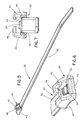
- FIG. 1 is a top perspective view of a cable tie according to the prior art
- FIG. 2 is a rear view of the cable tie of FIG. 1;
- FIG. 3 is a top perspective view of the cable tie of FIG. 1, shown surrounding a bundle of wires;
- FIG. 4 is a partial front view of the cable tie of FIG. 3;
- FIG. 5 is a top perspective view of a cable tie according to a first embodiment of the present invention.
- FIG. 6 is a partial rear perspective view of the cable tie of FIG. 5;
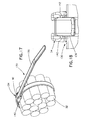
- FIG. 7 is a partial front view of the cable tie of FIG. 5;
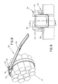
- FIG. 8 is a top perspective view of the cable tie of FIG. 5, shown surrounding a bundle of wires;
- FIG. 9 is a partial front view of the cable tie of FIG. 8;
- FIG. 10 is a partial cross-sectional view taken along lines 10-10 of FIG. 9;
- FIG. 11 is a partial cross-sectional view taken along lines 11-11 of FIG. 10;
- FIG. 12 is a partial enlarged top perspective view of the cable tie of FIG. 8;
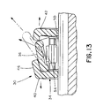
- FIG. 13 is a front sectional view of the cable tie of FIG. 12, with the strap broken away and showing the cable tie as it is released;
- FIG. 14 is a partial top perspective view of a cable tie according to a second embodiment of the present invention.
- FIG. 15 is a partial rear perspective view of the cable tie of FIG. 14;
- FIG. 16 is a partial front view of the cable tie of FIG. 14;
- FIG. 17 is a top perspective view of the cable tie of FIG. 14, shown surrounding a bundle of wires;
- FIG. 18 is a partial front view of the cable tie of FIG. 17;
- FIG. 19 is a front sectional view of the cable tie of FIG. 17, showing the cable tie as it is released;
- FIG. 20 is a partial top perspective view of the cable tie of FIG. 8, shown attached to a hand tool;
- FIG. 21 is a partial side view of the hand tool and cable tie of FIG. 20;
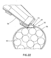
- FIG. 22 is a partial side view of the hand tool and cable tie of FIG. 20, showing the hand tool prior to cutting the cable tie;
- FIG. 23 is a partial top perspective view of the hand tool and cable tie of FIG. 20, showing the hand tool after cutting the cable tie.
- FIGS. 5-23 illustrate releasable in-line cable ties 30, 130. Specifically, FIGS. 5-13 and 20-23 are directed to cable tie 30, and FIGS. 14-19 are directed to cable tie 130. Cable ties 30, 130 are integrally molded from a suitable polymeric thermoplastic material, such as 6.6 nylon securing a bundle of cables 32, 132. It is likewise contemplated that cable ties 30, 130 may be molded from other grades of nylon or non-nylon material.
- cable tie 30 includes a head 34 and a strap 36.
- Strap 36 is formed in any desired length necessary to encompass the diameter of the object to be fastened.
- strap 36 includes a plurality of teeth 38 longitudinally spaced along an inner surface of strap 36.
- head 34 is formed with first and second side walls 40 and 42, end wall 44 and top wall 46 that define therebetween a strap positioning channel 48 (see FIG. 7).
- Locking wedge 50 is attached to end wall 44 by pivotal hinge 52, and wedge 50 has a plurality of teeth 54. As shown in FIG. 10, teeth 54 engage teeth 38 of strap 36 when strap 36 is inserted into channel 48.
- cable tie 30 can be applied using a standard cable tie tensioning and strap severing application tool, such as hand tool 56.
- Strap 36 can be used for temporary bundling while a harness or wire bundle is being built, and then cut off at the end for a clean final assembly with no tail protruding from head 34, as best seen in FIG. 23.
- top wall 46 extends from first side wall 40 of head 34 and covers approximately half of channel 48.
- strap 36 is supported not only by first and second side walls 40 and 42, but also partially by bridge 46.
- This design allows strap 36 to be lifted by hand or hand tool 56, without automatically releasing cable tie 30.
- cable tie 30 may be released only by twisting strap 36 in a certain direction.
- strap 36 is secured within head 34 using a hand or hand tool 56, as shown in FIG. 20.
- Hand tool 56 then trims excess strap 36, leaving the cable tie shown in FIG. 23.
- strap 36 is supported by first and second end walls 40 and 42, as well as bridge 46, strap 36 may be lifted by hand or by hand tool 56 without releasing cable tie 30.
- cable tie 30 may be released only by twisting strap 36 in a counterclockwise direction.
- second side wall 42 deflects outward, thus allowing strap 36 to exit channel 48.
- bridge 46 may extend from second side wall 42. In such an arrangement, cable tie 30 would be released by twisting strap 36 in a clockwise direction. In either orientation, cable tie 30 may be applied with hand tool 56 without automatically releasing.
- FIGS. 14-19 illustrate cable tie 130.
- Cable tie 130 is similar to cable tie 30 shown in FIGS. 5-13 and 20-23, except cable tie 130 lacks a top wall or partial bridge.
- cable tie 130 has an open top, as best seen in FIG. 16.
- Strap 136 may be released from head 134 by lifting upwards using a hand or hand tool, as best seen in FIG. 19. The upward force (in the direction of the arrow) creates a sideways force component on the first and second side walls 140 and 142 causing the side walls 140 and 142 to deflect outward, thus allowing strap 136 to exit strap positioning channel 148.
- cable tie 130 acts as a tension-limiting device, preventing an object from being bundled tightly with a hand tool. This is an important feature for cable ties used with communication wires, because overtightening can cause loss of transmission performance.
- the releasable in-line cable tie may be applied with a hand tool without automatically releasing.
- the releasable in-line cable tie may act as a tension-limiting device. It should be noted that the above-described illustrated embodiments and preferred embodiments of the invention are not an exhaustive listing of the form such a releasable in-line cable tie in accordance with the invention might take; rather, they serve as exemplary and illustrative of embodiments of the invention as presently understood.
Landscapes
- Engineering & Computer Science (AREA)
- Mechanical Engineering (AREA)
- Package Frames And Binding Bands (AREA)
- Installation Of Indoor Wiring (AREA)
- Electric Cable Installation (AREA)
- Clamps And Clips (AREA)
Abstract
A cable tie includes a strap having a first end and a second end opposite the first end and a head (34) secured to the first end of the strap. The head has a first side wall (40), a second side wall (42), an end wall (44) and a top wall (46) defining therebetween a strap accepting channel (48). The top wall extends from the first side wall toward the second side wall and covers only a portion of the channel.
Description
- This application claims priority to
U.S. Provisional Application Serial No. 60/707,595, filed on August 12, 2005 - The present invention is directed to a cable tie having a locking head at a first end that secures a second end of a strap to form a loop fastener and, more particularly, an in-line cable tie having a releasable locking mechanism that allows removal of the second end of the strap from the locking head without destroying the locking mechanism such that a cable tie can be removed and reused.
- FIGS. 1-4 illustrate the in-line cable tie disclosed in
U.S. D444,054 , owned by the Assignee of the present application, which is incorporated herein by reference. However, this in-line cable tie is not releasable or reusable. -
U.S. Pat. No. 5,193,250 , also owned by the Assignee of the present application, discloses a releasable cable tie. However, this cable tie is not an in-line cable tie and, thus, cannot be easily released by hand by applying upward force to the cable tie. - It would be desirable to provide a releasable cable tie that may be applied with a hand tool without automatically releasing.
- It would also be desirable to provide a releasable cable tie that acts as a tension-limiting device.
- It would further be desirable to provide a releasable cable tie that is easily releasable by hand by applying upward force to the cable tie.
- It would also be desirable to provide a releasable cable tie having a low profile locking head.
- FIG. 1 is a top perspective view of a cable tie according to the prior art;
- FIG. 2 is a rear view of the cable tie of FIG. 1;
- FIG. 3 is a top perspective view of the cable tie of FIG. 1, shown surrounding a bundle of wires;
- FIG. 4 is a partial front view of the cable tie of FIG. 3;
- FIG. 5 is a top perspective view of a cable tie according to a first embodiment of the present invention;
- FIG. 6 is a partial rear perspective view of the cable tie of FIG. 5;
- FIG. 7 is a partial front view of the cable tie of FIG. 5;
- FIG. 8 is a top perspective view of the cable tie of FIG. 5, shown surrounding a bundle of wires;
- FIG. 9 is a partial front view of the cable tie of FIG. 8;
- FIG. 10 is a partial cross-sectional view taken along lines 10-10 of FIG. 9;
- FIG. 11 is a partial cross-sectional view taken along lines 11-11 of FIG. 10;
- FIG. 12 is a partial enlarged top perspective view of the cable tie of FIG. 8;
- FIG. 13 is a front sectional view of the cable tie of FIG. 12, with the strap broken away and showing the cable tie as it is released;
- FIG. 14 is a partial top perspective view of a cable tie according to a second embodiment of the present invention;
- FIG. 15 is a partial rear perspective view of the cable tie of FIG. 14;
- FIG. 16 is a partial front view of the cable tie of FIG. 14;
- FIG. 17 is a top perspective view of the cable tie of FIG. 14, shown surrounding a bundle of wires;
- FIG. 18 is a partial front view of the cable tie of FIG. 17;
- FIG. 19 is a front sectional view of the cable tie of FIG. 17, showing the cable tie as it is released;
- FIG. 20 is a partial top perspective view of the cable tie of FIG. 8, shown attached to a hand tool;
- FIG. 21 is a partial side view of the hand tool and cable tie of FIG. 20;
- FIG. 22 is a partial side view of the hand tool and cable tie of FIG. 20, showing the hand tool prior to cutting the cable tie; and
- FIG. 23 is a partial top perspective view of the hand tool and cable tie of FIG. 20, showing the hand tool after cutting the cable tie.
- FIGS. 5-23 illustrate releasable in-line cable ties 30, 130. Specifically, FIGS. 5-13 and 20-23 are directed to
cable tie 30, and FIGS. 14-19 are directed tocable tie 130.Cable ties cables cable ties - As shown in FIG. 5,
cable tie 30 includes ahead 34 and astrap 36.Strap 36 is formed in any desired length necessary to encompass the diameter of the object to be fastened. As best seen in FIG. 10,strap 36 includes a plurality ofteeth 38 longitudinally spaced along an inner surface ofstrap 36. - As best seen in FIG. 6,
head 34 is formed with first andsecond side walls end wall 44 andtop wall 46 that define therebetween a strap positioning channel 48 (see FIG. 7).Locking wedge 50 is attached toend wall 44 bypivotal hinge 52, andwedge 50 has a plurality ofteeth 54. As shown in FIG. 10,teeth 54 engageteeth 38 ofstrap 36 whenstrap 36 is inserted intochannel 48. - As shown in FIGS. 20-23,
cable tie 30 can be applied using a standard cable tie tensioning and strap severing application tool, such ashand tool 56.Strap 36 can be used for temporary bundling while a harness or wire bundle is being built, and then cut off at the end for a clean final assembly with no tail protruding fromhead 34, as best seen in FIG. 23. - As shown in FIG. 7,
top wall 46, orpartial bridge 46, extends fromfirst side wall 40 ofhead 34 and covers approximately half ofchannel 48. Thus,strap 36 is supported not only by first andsecond side walls bridge 46. This design allowsstrap 36 to be lifted by hand orhand tool 56, without automatically releasingcable tie 30. As shown in FIGS. 12 and 13,cable tie 30 may be released only by twistingstrap 36 in a certain direction. - In operation,
strap 36 is secured withinhead 34 using a hand orhand tool 56, as shown in FIG. 20.Hand tool 56 then trimsexcess strap 36, leaving the cable tie shown in FIG. 23. Becausestrap 36 is supported by first andsecond end walls bridge 46,strap 36 may be lifted by hand or byhand tool 56 without releasingcable tie 30. As best seen in FIG. 12,cable tie 30 may be released only by twistingstrap 36 in a counterclockwise direction. As shown in FIG. 13,second side wall 42 deflects outward, thus allowingstrap 36 toexit channel 48. It is likewise contemplated thatbridge 46 may extend fromsecond side wall 42. In such an arrangement,cable tie 30 would be released by twistingstrap 36 in a clockwise direction. In either orientation,cable tie 30 may be applied withhand tool 56 without automatically releasing. - FIGS. 14-19
illustrate cable tie 130.Cable tie 130 is similar tocable tie 30 shown in FIGS. 5-13 and 20-23, exceptcable tie 130 lacks a top wall or partial bridge. Thus,cable tie 130 has an open top, as best seen in FIG. 16.Strap 136 may be released fromhead 134 by lifting upwards using a hand or hand tool, as best seen in FIG. 19. The upward force (in the direction of the arrow) creates a sideways force component on the first andsecond side walls side walls strap 136 to exitstrap positioning channel 148. In addition to being releasable and reusable,cable tie 130 acts as a tension-limiting device, preventing an object from being bundled tightly with a hand tool. This is an important feature for cable ties used with communication wires, because overtightening can cause loss of transmission performance. - The releasable in-line cable tie may be applied with a hand tool without automatically releasing. Alternatively, the releasable in-line cable tie may act as a tension-limiting device. It should be noted that the above-described illustrated embodiments and preferred embodiments of the invention are not an exhaustive listing of the form such a releasable in-line cable tie in accordance with the invention might take; rather, they serve as exemplary and illustrative of embodiments of the invention as presently understood.
Claims (6)
- A cable tie comprising:a strap having a first end and a second end opposite the first end; anda head secured to the first end of the strap, the head having a first side wall, a second side wall, an end wall and a top wall defining therebetween a strap accepting channel,wherein the top wall extends from the first side wall toward the second side wall and covers only a portion of the channel.
- The cable tie of claim 1, wherein the top wall covers approximately half of the channel.
- The cable tie of claim 1, wherein the strap is released from the head by twisting the strap in a clockwise or counterclockwise direction.
- The cable tie of claim 3, wherein upon twisting the strap in the clockwise or counterclockwise direction, the first side wall deflects away from the second side wall allowing the strap to be released from the head.
- A cable tie comprising:a strap having a first end and a second end opposite the first end; anda head secured to the first end of the strap, the head having a first side wall, a second side wall and an end wall defining therebetween a strap accepting channel,wherein the strap is released from the head by pulling the strap away from the end wall.
- The cable tie of claim 5, wherein upon pulling the strap away from the end wall, the first side wall deflects away from the second side wall allowing the strap to be released from the head.
Applications Claiming Priority (2)
| Application Number | Priority Date | Filing Date | Title |
|---|---|---|---|
| US70759505P | 2005-08-12 | 2005-08-12 | |
| US11/463,459 US20070033772A1 (en) | 2005-08-12 | 2006-08-09 | Releasable in-line cable tie |
Publications (1)
| Publication Number | Publication Date |
|---|---|
| EP1752384A2 true EP1752384A2 (en) | 2007-02-14 |
Family
ID=37401373
Family Applications (1)
| Application Number | Title | Priority Date | Filing Date |
|---|---|---|---|
| EP06254246A Pending EP1752384A2 (en) | 2005-08-12 | 2006-08-10 | Releasable in-line cable tie |
Country Status (3)
| Country | Link |
|---|---|
| US (1) | US20070033772A1 (en) |
| EP (1) | EP1752384A2 (en) |
| JP (1) | JP2007112511A (en) |
Cited By (4)
| Publication number | Priority date | Publication date | Assignee | Title |
|---|---|---|---|---|
| WO2008136660A1 (en) | 2007-05-04 | 2008-11-13 | Willem Hienekamp | Tightenable clamping device, suitable for application in tie wraps |
| WO2009094693A1 (en) * | 2008-01-30 | 2009-08-06 | Biggers Investments Pty Ltd | Cable tie |
| EP2194282A4 (en) * | 2007-09-28 | 2011-10-05 | Jms Co Ltd | Band and bag set |
| NL1038880C2 (en) * | 2011-06-22 | 2013-01-02 | Willem Hienekamp | SPANTABLE RELEASABLE CLUTCH WITH QUICK OPERATION. |
Families Citing this family (11)
| Publication number | Priority date | Publication date | Assignee | Title |
|---|---|---|---|---|
| US7866005B2 (en) * | 2008-01-09 | 2011-01-11 | Panduit Corp. | Elastomeric releasable cable tie |
| KR101240825B1 (en) | 2011-11-30 | 2013-03-11 | 김호식 | Reusable tie-band |
| US9266653B1 (en) * | 2013-11-14 | 2016-02-23 | Stephen J. Housser | Flush cut tie device |
| FR3022531B1 (en) | 2014-06-23 | 2016-07-15 | Caillau Ets | TIGHTENING NECKLACE WITH A TRANSVERSE LOOP |
| WO2015198965A1 (en) * | 2014-06-26 | 2015-12-30 | 株式会社パイオラックス | Binding band |
| US10427849B2 (en) | 2015-06-04 | 2019-10-01 | Advanced Cable Ties, Inc. | Cable tie adapter |
| US9656591B1 (en) | 2015-08-27 | 2017-05-23 | Jayson Dumenigo | Securing strap having at least one strap securing interface |
| KR200481773Y1 (en) * | 2016-03-03 | 2016-11-08 | 프타 주식회사 | Cable tie for incision type |
| US10479574B2 (en) | 2017-01-17 | 2019-11-19 | Daniel J. Vorhis | Reusable cable tie |
| USD939791S1 (en) * | 2018-03-27 | 2021-12-28 | Maurice Myerson | Scoop, holder and base combination |
| EP4037992B1 (en) * | 2019-10-01 | 2024-04-24 | C.B. Srl Costruzioni Brescianini | Cable tie |
Family Cites Families (41)
| Publication number | Priority date | Publication date | Assignee | Title |
|---|---|---|---|---|
| US3147522A (en) * | 1960-06-01 | 1964-09-08 | Schumm Erich | Flexible tie |
| US3118200A (en) * | 1961-08-01 | 1964-01-21 | Bell Charles Cox | Cable strap |
| GB948900A (en) * | 1961-12-22 | 1964-02-05 | Schumm Erich | Improvements in or relating to ties of resilient flexible material |
| US3086265A (en) * | 1962-01-02 | 1963-04-23 | Orenick Michael | Closure means for bags |
| FI46352C (en) * | 1963-01-23 | 1973-03-12 | Schumm | Resin made of synthetic resin, rubber or similar material. |
| US3257694A (en) * | 1963-03-21 | 1966-06-28 | Walter J Litwin | Self-locking tamper proof strap |
| BE756222A (en) * | 1969-09-17 | 1971-03-16 | Thomas & Betts Corp | OBJECT CLAMPING BAND |
| US3731347A (en) * | 1971-03-16 | 1973-05-08 | Panduit Corp | Cable tie |
| US3837047A (en) * | 1973-11-26 | 1974-09-24 | Amp Inc | Molded plastic bundle tie |
| US3886630A (en) * | 1974-07-15 | 1975-06-03 | Manx Mail Order Limited | Cable tie clips |
| FR2448064A1 (en) * | 1979-01-30 | 1980-08-29 | Legrand Sa | TIGHTENING COLLAR |
| US4393548A (en) * | 1980-08-04 | 1983-07-19 | Thomas & Betts Corporation | Folded head cable tie and methods for making and using the same |
| FR2513328A1 (en) * | 1981-09-23 | 1983-03-25 | Legrand Sa | TIGHTENING NECK |
| US4507828A (en) * | 1983-07-18 | 1985-04-02 | Japan Bano'k Co., Ltd. | Bundling belt device |
| US4765032A (en) * | 1987-03-11 | 1988-08-23 | Thomas & Betts Corporation | Environmental bundling tie |
| US4868953A (en) * | 1987-03-11 | 1989-09-26 | Thomas & Betts Corporation | Environmental bundling tie |
| JPH0182165U (en) * | 1987-11-18 | 1989-06-01 | ||
| CA2047945C (en) * | 1990-08-02 | 1995-04-04 | William A. Fortsch | Cable tie having improved locking barb |
| DE4126225A1 (en) * | 1991-08-08 | 1993-02-11 | Schumm Erich Kg | SEALING TAPE |
| US5193250A (en) * | 1992-04-30 | 1993-03-16 | Panduit Corp. | Releasable cable tie |
| US5317787B1 (en) * | 1992-10-01 | 1995-11-28 | Thomas & Betts Corp | Cable tie having improved tail gripping and holding feature |
| GB2285475B (en) * | 1994-01-07 | 1997-09-24 | Thomas & Betts Corp | Improvements in cable ties |
| CA2146828A1 (en) * | 1994-04-15 | 1995-10-16 | Peter M. Wells, Jr. | Cable tie having an improved strap body |
| US5513421A (en) * | 1994-04-15 | 1996-05-07 | Thomas & Betts Corporation | Cable tie having an improved strap locking device |
| US5621949A (en) * | 1995-04-07 | 1997-04-22 | Thomas & Betts Corproation | Barbed cable tie |
| DE69607085T2 (en) * | 1995-08-22 | 2001-03-22 | Thomas & Betts Corp. (N.D.Ges.D. Staates New Jersey), Memphis | Self-locking cable tie with symmetrical structure |
| US6003208A (en) * | 1995-12-13 | 1999-12-21 | Tyton Hellerman Corporation | Parallel entry tie |
| GB2308153B (en) * | 1995-12-13 | 2000-08-16 | Bowthorpe Plc | Parallel entry tie |
| US5815891A (en) * | 1997-02-06 | 1998-10-06 | Thomas & Betts Corporation | Cable tie with bent barb |
| USD422487S (en) * | 1997-03-21 | 2000-04-11 | Thomas & Betts Corporation | Double pawl parallel-entry cable tie |
| USD419861S (en) * | 1997-03-21 | 2000-02-01 | Thomas & Betts Corporation | Single pawl parallel-entry cable tie |
| US5745957A (en) * | 1997-03-26 | 1998-05-05 | Thomas & Betts Corporation | In-line cable tie |
| US6185792B1 (en) * | 1997-11-21 | 2001-02-13 | Thomas & Betts International, Inc. | Bi-directional self-locking cable tie |
| DE69823617D1 (en) * | 1997-12-01 | 2004-06-09 | Thomas & Betts Int | Improved cable tie with locking head and separate binding strip |
| US6185791B1 (en) * | 1998-03-09 | 2001-02-13 | Thomas & Betts International, Inc. | Releasable cable tie |
| US6076235A (en) * | 1999-04-20 | 2000-06-20 | Thomas & Betts International, Inc | Cable tie |
| US6226839B1 (en) * | 1999-01-05 | 2001-05-08 | Adel Odeh Sayegh | Securing means attachable to objects of varying size and shape |
| SE514656C2 (en) * | 1999-09-21 | 2001-03-26 | Biwex Ab | Device at a bundling band |
| USD444054S1 (en) * | 2000-05-08 | 2001-06-26 | Panduit Corp. | Low profile cable tie |
| US6698067B2 (en) * | 2002-01-30 | 2004-03-02 | Thomas & Betts International, Inc. | Locking strap with handling structure |
| SE521799C2 (en) * | 2003-04-03 | 2003-12-09 | Gepe Dev Ag | Device for a bundle tie |
-
2006
- 2006-08-09 US US11/463,459 patent/US20070033772A1/en not_active Abandoned
- 2006-08-10 EP EP06254246A patent/EP1752384A2/en active Pending
- 2006-08-11 JP JP2006219398A patent/JP2007112511A/en active Pending
Cited By (6)
| Publication number | Priority date | Publication date | Assignee | Title |
|---|---|---|---|---|
| WO2008136660A1 (en) | 2007-05-04 | 2008-11-13 | Willem Hienekamp | Tightenable clamping device, suitable for application in tie wraps |
| EP2194282A4 (en) * | 2007-09-28 | 2011-10-05 | Jms Co Ltd | Band and bag set |
| US8302264B2 (en) | 2007-09-28 | 2012-11-06 | Jms Co., Ltd. | Band and bag set |
| WO2009094693A1 (en) * | 2008-01-30 | 2009-08-06 | Biggers Investments Pty Ltd | Cable tie |
| EP2238379A4 (en) * | 2008-01-30 | 2011-06-22 | Dual Tie Concepts Pty Ltd | Cable tie |
| NL1038880C2 (en) * | 2011-06-22 | 2013-01-02 | Willem Hienekamp | SPANTABLE RELEASABLE CLUTCH WITH QUICK OPERATION. |
Also Published As
| Publication number | Publication date |
|---|---|
| US20070033772A1 (en) | 2007-02-15 |
| JP2007112511A (en) | 2007-05-10 |
Similar Documents
| Publication | Publication Date | Title |
|---|---|---|
| US20070033772A1 (en) | Releasable in-line cable tie | |
| US7866006B2 (en) | Cable tie having detachable tail | |
| US6186451B1 (en) | Cable tie | |
| JP6945687B2 (en) | Integrated release structure for claw latch device | |
| US7281302B2 (en) | Cable tie | |
| US6578239B2 (en) | Low profile latchable tie | |
| EP1260452A3 (en) | Cable tie with wide neck | |
| US7779515B2 (en) | Two-piece cable tie suitable for use in an automated cable tie installation tool | |
| KR101990778B1 (en) | Reusable Cable Ties | |
| WO2004064215A1 (en) | Cable clamps | |
| US20120233818A1 (en) | Cable tie with an improved buckle | |
| CN100344512C (en) | Device in a bundle tie | |
| WO2009084302A1 (en) | Wire harness fastener | |
| US20110061209A1 (en) | Cable tie | |
| CN212314406U (en) | Easy-to-disassemble type binding band | |
| KR100662079B1 (en) | Binding band | |
| CN219949152U (en) | Combined ribbon capable of being spliced | |
| JP4303066B2 (en) | Stopper and binding device using the same | |
| KR102432945B1 (en) | Automotive wire bundle fixture | |
| JP2003160070A (en) | WIRE HARNESS REMOVING COMPONENT AND WIRE HARNESS WITH THE SAME | |
| CN110921095A (en) | Easy-to-disassemble type binding band | |
| JPH0627613U (en) | cable tie | |
| KR19990035125A (en) | Recyclable Tie | |
| JP2018057610A (en) | Cutter for binding band | |
| JP2000065253A (en) | Unity band |
Legal Events
| Date | Code | Title | Description |
|---|---|---|---|
| PUAI | Public reference made under article 153(3) epc to a published international application that has entered the european phase |
Free format text: ORIGINAL CODE: 0009012 |
|
| AK | Designated contracting states |
Kind code of ref document: A2 Designated state(s): AT BE BG CH CY CZ DE DK EE ES FI FR GB GR HU IE IS IT LI LT LU LV MC NL PL PT RO SE SI SK TR |
|
| AX | Request for extension of the european patent |
Extension state: AL BA HR MK YU |
|
| D18D | Application deemed to be withdrawn (deleted) | ||
| STAA | Information on the status of an ep patent application or granted ep patent |
Free format text: STATUS: THE APPLICATION IS DEEMED TO BE WITHDRAWN |
|
| 18D | Application deemed to be withdrawn |
Effective date: 20100302 |