EP4037992B1 - Cable tie - Google Patents
Cable tie Download PDFInfo
- Publication number
- EP4037992B1 EP4037992B1 EP20775631.3A EP20775631A EP4037992B1 EP 4037992 B1 EP4037992 B1 EP 4037992B1 EP 20775631 A EP20775631 A EP 20775631A EP 4037992 B1 EP4037992 B1 EP 4037992B1
- Authority
- EP
- European Patent Office
- Prior art keywords
- tie
- plate
- teeth
- cable
- slots
- Prior art date
- Legal status (The legal status is an assumption and is not a legal conclusion. Google has not performed a legal analysis and makes no representation as to the accuracy of the status listed.)
- Active
Links
- 230000014759 maintenance of location Effects 0.000 claims description 11
- 238000003780 insertion Methods 0.000 description 4
- 230000037431 insertion Effects 0.000 description 4
- 230000000670 limiting effect Effects 0.000 description 2
- 230000008878 coupling Effects 0.000 description 1
- 238000010168 coupling process Methods 0.000 description 1
- 238000005859 coupling reaction Methods 0.000 description 1
- 239000000446 fuel Substances 0.000 description 1
- 239000000463 material Substances 0.000 description 1
- 238000012986 modification Methods 0.000 description 1
- 230000004048 modification Effects 0.000 description 1
Images

Classifications
-
- B—PERFORMING OPERATIONS; TRANSPORTING
- B65—CONVEYING; PACKING; STORING; HANDLING THIN OR FILAMENTARY MATERIAL
- B65D—CONTAINERS FOR STORAGE OR TRANSPORT OF ARTICLES OR MATERIALS, e.g. BAGS, BARRELS, BOTTLES, BOXES, CANS, CARTONS, CRATES, DRUMS, JARS, TANKS, HOPPERS, FORWARDING CONTAINERS; ACCESSORIES, CLOSURES, OR FITTINGS THEREFOR; PACKAGING ELEMENTS; PACKAGES
- B65D63/00—Flexible elongated elements, e.g. straps, for bundling or supporting articles
- B65D63/10—Non-metallic straps, tapes, or bands; Filamentary elements, e.g. strings, threads or wires; Joints between ends thereof
- B65D63/1018—Joints produced by application of integral securing members, e.g. buckles, wedges, tongue and slot, locking head and teeth or the like
- B65D63/1027—Joints produced by application of integral securing members, e.g. buckles, wedges, tongue and slot, locking head and teeth or the like the integral securing member being formed as a female and male locking member, e.g. locking head and locking teeth, or the like
- B65D63/1063—Joints produced by application of integral securing members, e.g. buckles, wedges, tongue and slot, locking head and teeth or the like the integral securing member being formed as a female and male locking member, e.g. locking head and locking teeth, or the like the female locking member being provided with at least one plastic barb
-
- B—PERFORMING OPERATIONS; TRANSPORTING
- B65—CONVEYING; PACKING; STORING; HANDLING THIN OR FILAMENTARY MATERIAL
- B65D—CONTAINERS FOR STORAGE OR TRANSPORT OF ARTICLES OR MATERIALS, e.g. BAGS, BARRELS, BOTTLES, BOXES, CANS, CARTONS, CRATES, DRUMS, JARS, TANKS, HOPPERS, FORWARDING CONTAINERS; ACCESSORIES, CLOSURES, OR FITTINGS THEREFOR; PACKAGING ELEMENTS; PACKAGES
- B65D63/00—Flexible elongated elements, e.g. straps, for bundling or supporting articles
- B65D63/10—Non-metallic straps, tapes, or bands; Filamentary elements, e.g. strings, threads or wires; Joints between ends thereof
- B65D63/1018—Joints produced by application of integral securing members, e.g. buckles, wedges, tongue and slot, locking head and teeth or the like
- B65D63/1027—Joints produced by application of integral securing members, e.g. buckles, wedges, tongue and slot, locking head and teeth or the like the integral securing member being formed as a female and male locking member, e.g. locking head and locking teeth, or the like
-
- B—PERFORMING OPERATIONS; TRANSPORTING
- B65—CONVEYING; PACKING; STORING; HANDLING THIN OR FILAMENTARY MATERIAL
- B65D—CONTAINERS FOR STORAGE OR TRANSPORT OF ARTICLES OR MATERIALS, e.g. BAGS, BARRELS, BOTTLES, BOXES, CANS, CARTONS, CRATES, DRUMS, JARS, TANKS, HOPPERS, FORWARDING CONTAINERS; ACCESSORIES, CLOSURES, OR FITTINGS THEREFOR; PACKAGING ELEMENTS; PACKAGES
- B65D2563/00—Flexible elongated elements, e.g. straps for bundling or supporting atricles
- B65D2563/10—Non-metallic straps, tapes or bands; Filamentary elements, e.g. strings, threads, wires; Joints between ends thereof
- B65D2563/101—Details of non-metallic straps, tapes or bands
- B65D2563/103—Details of non-metallic straps, tapes or bands details of the male locking member, e.g. locking teeth on the strap
- B65D2563/106—Details of non-metallic straps, tapes or bands details of the male locking member, e.g. locking teeth on the strap formed as a ladder-like structure
-
- B—PERFORMING OPERATIONS; TRANSPORTING
- B65—CONVEYING; PACKING; STORING; HANDLING THIN OR FILAMENTARY MATERIAL
- B65D—CONTAINERS FOR STORAGE OR TRANSPORT OF ARTICLES OR MATERIALS, e.g. BAGS, BARRELS, BOTTLES, BOXES, CANS, CARTONS, CRATES, DRUMS, JARS, TANKS, HOPPERS, FORWARDING CONTAINERS; ACCESSORIES, CLOSURES, OR FITTINGS THEREFOR; PACKAGING ELEMENTS; PACKAGES
- B65D2563/00—Flexible elongated elements, e.g. straps for bundling or supporting atricles
- B65D2563/10—Non-metallic straps, tapes or bands; Filamentary elements, e.g. strings, threads, wires; Joints between ends thereof
- B65D2563/101—Details of non-metallic straps, tapes or bands
- B65D2563/107—Details of non-metallic straps, tapes or bands having a release mechanism, e.g. reusable bundling straps
Definitions
- the present invention relates to a cable tie. More specifically, the invention relates to a cable tie of extremely low weight with respect to conventional ties.
- cable ties are constituted by an elongated body which is provided with a plurality of teeth which are arranged along the entire extension of the body of the tie, and which engage adapted slots which are defined at a well-delimited region of the tie.
- the user wraps the tie around a cable to be tied and pulls the tie by acting on a traction element, making the tie slide until the teeth of the body of the tie engage the slots, in so doing fixing the cable.
- Ties of the type that can be reopened must be reopened using two hands, threading the entire body of the tie along all its length.
- KR 2010 0122164 A discloses a cable tie having a head at an end thereof provided with a pair of retention teeth and an engagement tooth configured to interact with an elongated portion of the cable tie provided with corresponding slots.
- JP S53 30200 U and JP S49 17691 U disclose cable ties provided at an end thereof with a traction ring and at an opposite end with a head comprising a pair of retention teeth and engagement teeth configured to interact with an elongated portion of the cable tie provided with corresponding engagement teeth.
- the aim of the present invention is to provide a cable tie that has reduced weight compared to conventional ties.
- an object of the present invention is to provide a cable tie wherein the insertion of the tie can occur without necessarily having to make the entire body of the tie slide through the tightening region.
- Another object of the present invention is to provide a tie that offers rapid disengagement.
- Another object of the present invention is to provide a cable tie that has a holding capacity at least equal to that of conventional ties.
- Another object of the present invention is to provide a cable tie that is highly reliable, easily and practically implemented and of low cost.
- the cable tie according to the invention generally designated by the reference numeral 1, comprises an elongated (band-like) tie body 2 which is provided with a plurality of slots 3 which are arranged transversely along the extension of the elongated body 2, substantially along the entire portion of body that is used for tightening.
- the slots 3 make it possible to considerably reduce the weight of the tie and make it possible at the same time to ensure the coupling and the tightening of the tie around a cable or rather a plurality of conducting cables 5, as shown in Figure 4 .
- the tie body 2 is provided at one end with a plate-like element 6 which is provided centrally with a plurality of engagement teeth 7 which are adapted to engage the slots 3 of the tie body 2.
- the plate-like element 6 is further provided with a pair of retention teeth 8 which allow both the passage of the tie body 2 by translation through them, as happens in a normal tie, taking advantage of the narrowing of the cross-section 9 of the tie body 2 for the insertion between the pair of facing teeth 8, and also allow an insertion of the tie body 2 at any intermediate point thereof. This is due to the presence of inclined planes 9 which are defined at the upper end of the facing teeth 8, which allow the inclined insertion of the tie body 2 and its positioning at the lower end of the teeth 8, adjacent to the plate-like element 6, and with the teeth 7 engaged in the slots 3.
- the engagement teeth 7 have a face that is inclined with respect to the surface of the plate-like element and a face that is perpendicular to the surface of the plate-like element.
- the plate-like element 6 has a reduced thickness below the engagement teeth 7, i.e. the plate-like element 6 is hollowed out and is provided with a recess 10.
- the recess 10 confers flexibility to the plate-like element 6 and allows the tie body 2 to slide between the plate-like element 6 and the retention teeth 8.
- the tightening occurs by acting on a ring 11 which is present at the end of the tie body 2 which is opposite to the end where the plate-like element 6 is present.
- the ring 11 is then pulled in order to enable the tightening.
- the action of pulling the ring 11 ensures that the tie body 2 slides over the teeth 7 with the plate-like element 6 flexing and so allowing the tie body 2 to jump from one tooth to the next and therefore to locate the suitable slot 3 for engaging the tooth 7, so as to ensure the required tightening.
- the plate-like element 6 is provided in a lower region with at least one pair of raised portions 12 which constitute protrusions from the lower surface of the plate-like element 6 and allow a further tightening action against the conducting cables 5 or corrugated tubes that need to be bound by the tie according to the invention.
- the tie according to the invention allows an extremely rapid opening (reopening), using one hand only and without needing to cut the tie.
- the user can act on the ring 11, with one hand pulling upward, toward the fastening region.
- the retention teeth 8, being elastic, yield and allow the elongated (band-like) body to exit, thus allowing the tie to be disengaged.
- the cable tie according to the invention makes it possible to have reduced weight with respect to conventional ties and this is an enormous advantage if the tie is used for example in motor vehicles.
- the tie can be coupled without threading the tie body completely through the tightening region (plate-like element and retention teeth), but simply by choosing a suitable position for the body of the tie, so as to be able to make the body slide only for a minimum distance in order to execute the tightening.
- the materials used, as well as the contingent shapes and dimensions may be any according to the requirements and to the state of the art.
Landscapes
- Engineering & Computer Science (AREA)
- Mechanical Engineering (AREA)
- Package Frames And Binding Bands (AREA)
- Clamps And Clips (AREA)
- Bridges Or Land Bridges (AREA)
Description
- The present invention relates to a cable tie. More specifically, the invention relates to a cable tie of extremely low weight with respect to conventional ties.
- As is known, cable ties are constituted by an elongated body which is provided with a plurality of teeth which are arranged along the entire extension of the body of the tie, and which engage adapted slots which are defined at a well-delimited region of the tie.
- In this manner, the user wraps the tie around a cable to be tied and pulls the tie by acting on a traction element, making the tie slide until the teeth of the body of the tie engage the slots, in so doing fixing the cable.
- The above solution, although effective, entails a weight of the tie that is not negligible, and this, for example in the automotive sector, where ties are employed in great numbers, can have an impact on the final weight of the vehicle. Given the extreme need to reduce weight, also with the goal of containing the consumption of fuel, a "heavy" tie is undesirable.
- Furthermore, conventional ties, in order to be fastened, require that the body of the tie be made to slide fully through the tightening region, and it is not possible to decide to fasten the tie at an intermediate point of the body.
- This fact entails the need both to have enough space to be able to thread the body of the tie and tighten it, which is not always possible in the restricted spaces of an engine compartment, and also it entails a more complicated manual action by the user, who must use one hand to thread the body of the tie and make it slide in its entirety.
- Even furthermore, conventional ties need to be cut in order to be reopened. Ties of the type that can be reopened must be reopened using two hands, threading the entire body of the tie along all its length.
-
KR 2010 0122164 A JP S53 30200 U JP S49 17691 U - The aim of the present invention is to provide a cable tie that has reduced weight compared to conventional ties.
- Within this aim, an object of the present invention is to provide a cable tie wherein the insertion of the tie can occur without necessarily having to make the entire body of the tie slide through the tightening region.
- Another object of the present invention is to provide a tie that offers rapid disengagement.
- Another object of the present invention is to provide a cable tie that has a holding capacity at least equal to that of conventional ties.
- Another object of the present invention is to provide a cable tie that is highly reliable, easily and practically implemented and of low cost.
- This aim and these and other objects which will become better apparent hereinafter are achieved by a cable tie as defined in
claim 1 - Further characteristics and advantages of the invention will become better apparent from the detailed description of a preferred, but not exclusive, embodiment of the cable tie according to the invention, illustrated by way of non-limiting example in the accompanying drawings, wherein:
-
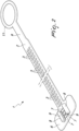
Figure 1 is a perspective view of a cable tie according to the present invention; -
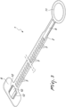
Figure 2 is a perspective view of the cable tie ofFigure 1 in the open configuration; -
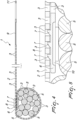
Figure 3 is a perspective view from below of the cable tie according to the invention; -
Figure 4 is a longitudinal cross-sectional view of the cable tie according to the invention, in the operating configuration; -
Figure 5 is a longitudinal cross-sectional view of a detail ofFigure 4 ; -
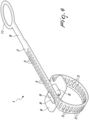
Figure 6 is a perspective view of the cable tie according to the invention in the tightened configuration. - With reference to the figures, the cable tie according to the invention, generally designated by the
reference numeral 1, comprises an elongated (band-like)tie body 2 which is provided with a plurality ofslots 3 which are arranged transversely along the extension of theelongated body 2, substantially along the entire portion of body that is used for tightening. - Conveniently, the
slots 3 make it possible to considerably reduce the weight of the tie and make it possible at the same time to ensure the coupling and the tightening of the tie around a cable or rather a plurality of conductingcables 5, as shown inFigure 4 . - The
tie body 2 is provided at one end with a plate-like element 6 which is provided centrally with a plurality ofengagement teeth 7 which are adapted to engage theslots 3 of thetie body 2. The plate-like element 6 is further provided with a pair ofretention teeth 8 which allow both the passage of thetie body 2 by translation through them, as happens in a normal tie, taking advantage of the narrowing of thecross-section 9 of thetie body 2 for the insertion between the pair of facingteeth 8, and also allow an insertion of thetie body 2 at any intermediate point thereof. This is due to the presence ofinclined planes 9 which are defined at the upper end of the facingteeth 8, which allow the inclined insertion of thetie body 2 and its positioning at the lower end of theteeth 8, adjacent to the plate-like element 6, and with theteeth 7 engaged in theslots 3. - The
engagement teeth 7 have a face that is inclined with respect to the surface of the plate-like element and a face that is perpendicular to the surface of the plate-like element. - According to the invention the plate-
like element 6 has a reduced thickness below theengagement teeth 7, i.e. the plate-like element 6 is hollowed out and is provided with arecess 10. - The
recess 10 confers flexibility to the plate-like element 6 and allows thetie body 2 to slide between the plate-like element 6 and theretention teeth 8. - In fact, when the user wishes to tighten the tie, whether he or she has inserted the
tie body 2 for its entire length through theretention teeth 8, or he or she has inserted it at an intermediate point thereof, as explained previously, the tightening occurs by acting on aring 11 which is present at the end of thetie body 2 which is opposite to the end where the plate-like element 6 is present. - The
ring 11 is then pulled in order to enable the tightening. The action of pulling thering 11 ensures that thetie body 2 slides over theteeth 7 with the plate-like element 6 flexing and so allowing thetie body 2 to jump from one tooth to the next and therefore to locate thesuitable slot 3 for engaging thetooth 7, so as to ensure the required tightening. - Conveniently, the plate-
like element 6 is provided in a lower region with at least one pair of raisedportions 12 which constitute protrusions from the lower surface of the plate-like element 6 and allow a further tightening action against the conductingcables 5 or corrugated tubes that need to be bound by the tie according to the invention. - The tie according to the invention allows an extremely rapid opening (reopening), using one hand only and without needing to cut the tie.
- In fact, the user can act on the
ring 11, with one hand pulling upward, toward the fastening region. Theretention teeth 8, being elastic, yield and allow the elongated (band-like) body to exit, thus allowing the tie to be disengaged. - In practice it has been found that the cable tie according to the invention makes it possible to have reduced weight with respect to conventional ties and this is an enormous advantage if the tie is used for example in motor vehicles.
- Furthermore, the tie can be coupled without threading the tie body completely through the tightening region (plate-like element and retention teeth), but simply by choosing a suitable position for the body of the tie, so as to be able to make the body slide only for a minimum distance in order to execute the tightening.
- The tie thus conceived is susceptible of numerous modifications and variations, all of which are within the scope of the appended claims.
- Moreover, all the details may be substituted by other, technically equivalent elements.
- In practice, the materials used, as well as the contingent shapes and dimensions, may be any according to the requirements and to the state of the art.
- Where technical features mentioned in any claim are followed by reference signs, those reference signs have been included for the sole purpose of increasing the intelligibility of the claims and accordingly, such reference signs do not have any limiting effect on the interpretation of each element identified by way of example by such reference signs.
Claims (5)
- A cable tie (1), comprising a tie body (2), said body (2) having an elongated shape and comprising at one end a plate-like element (6) and, at the opposite end, a traction ring (11), a pair of retention teeth (8) being arranged on said plate-like element (6), which face each other, said tie body (2) being provided with a plurality of slots (3) which are arranged along the extension thereof that is used for tightening, wherein said plate-like element (6) is provided with a plurality of engagement teeth (7) which are adapted to engage in said slots (3) of said tie body (2), the pair of retention teeth (8) being arranged on said plate-like element (6) perpendicular with respect to the extension of said engagement teeth (7), and wherein said plate-like element (6) is hollowed out and provided with a recess below the engagement teeth (7), so that the plate-like element (6) has a lower thickness at said engagement teeth (7), in order to allow flexibility of said plate-like element (6) when said tie body (2) is made to slide between said plate-like element (6) and said retention teeth (8).
- The tie according to claim 1, characterized in that said slots (3) are arranged transversely with respect to the extension of the tie body (2).
- The tie according to claim 1, characterized in that said retention teeth (8) are shaped with an inclined plane (9) at their upper end, in order to allow the engagement of said tie body (2) in an intermediate region of the body (2).
- The tie according to claim 1, characterized in that said engagement teeth (7) have a face that is inclined with respect to the surface of said plate-like element (6) and a face that is perpendicular to the surface of said plate-like element (6).
- The tie according to one or more of the preceding claims, characterized in that said plate-like element (6) is provided in a lower region with at least one pair of raised portions (12) which constitute protrusions from the lower surface of the plate-like element (6) and allow a further action to tighten the tie body.
Applications Claiming Priority (2)
| Application Number | Priority Date | Filing Date | Title |
|---|---|---|---|
| IT201900017600 | 2019-10-01 | ||
| PCT/EP2020/076310 WO2021063724A1 (en) | 2019-10-01 | 2020-09-21 | Cable tie |
Publications (2)
| Publication Number | Publication Date |
|---|---|
| EP4037992A1 EP4037992A1 (en) | 2022-08-10 |
| EP4037992B1 true EP4037992B1 (en) | 2024-04-24 |
Family
ID=69375880
Family Applications (1)
| Application Number | Title | Priority Date | Filing Date |
|---|---|---|---|
| EP20775631.3A Active EP4037992B1 (en) | 2019-10-01 | 2020-09-21 | Cable tie |
Country Status (8)
| Country | Link |
|---|---|
| US (1) | US12030700B2 (en) |
| EP (1) | EP4037992B1 (en) |
| CN (1) | CN114466802A (en) |
| BR (1) | BR112022006062A2 (en) |
| MA (1) | MA57250B1 (en) |
| MX (1) | MX2022003974A (en) |
| PL (1) | PL4037992T3 (en) |
| WO (1) | WO2021063724A1 (en) |
Families Citing this family (2)
| Publication number | Priority date | Publication date | Assignee | Title |
|---|---|---|---|---|
| US11781678B2 (en) * | 2020-10-14 | 2023-10-10 | Commscope Technologies Llc | Devices and methods for holding cables with non-uniform undulations |
| US11761559B2 (en) | 2020-10-14 | 2023-09-19 | Commscope Technologies Llc | Devices and methods for holding cables with non-uniform undulations |
Family Cites Families (22)
| Publication number | Priority date | Publication date | Assignee | Title |
|---|---|---|---|---|
| GB948900A (en) * | 1961-12-22 | 1964-02-05 | Schumm Erich | Improvements in or relating to ties of resilient flexible material |
| US3601527A (en) * | 1970-03-03 | 1971-08-24 | Synthetic Products Mfg Corp | Aerial cable tie |
| JPS4917691U (en) * | 1972-05-19 | 1974-02-14 | ||
| US3837047A (en) * | 1973-11-26 | 1974-09-24 | Amp Inc | Molded plastic bundle tie |
| US3991444A (en) * | 1976-02-18 | 1976-11-16 | Panduit Corporation | Releasable cable tie |
| JPS5635587Y2 (en) * | 1976-08-23 | 1981-08-21 | ||
| DE2717622A1 (en) * | 1977-04-21 | 1978-10-26 | Fastex Division Der Itw Ateco | ONE PIECE CABLE TAPE |
| US4805856A (en) * | 1987-12-29 | 1989-02-21 | Panduit Corp. | Cable mount |
| DE4126225A1 (en) * | 1991-08-08 | 1993-02-11 | Schumm Erich Kg | SEALING TAPE |
| US6226839B1 (en) * | 1999-01-05 | 2001-05-08 | Adel Odeh Sayegh | Securing means attachable to objects of varying size and shape |
| TWI266732B (en) * | 2004-05-25 | 2006-11-21 | Nichido Kogyo Kabushiki Kaisha | Hanger tie |
| US20070033772A1 (en) * | 2005-08-12 | 2007-02-15 | Panduit Corp. | Releasable in-line cable tie |
| ITMI20060133A1 (en) * | 2006-01-26 | 2007-07-27 | C B S R L | STRAP STRUCTURE FOR TEMPORARY FIXING OF PARTS DURING HANDLING AND ASSEMBLY ON PRODUCTION LINES |
| CN101809295B (en) * | 2007-09-28 | 2013-03-13 | 株式会社Jms | Band and bag set |
| US8726468B2 (en) * | 2009-03-18 | 2014-05-20 | Hellermanntyton Corporation | Bundle tie with head dampener |
| KR20100122164A (en) * | 2009-05-12 | 2010-11-22 | 배석균 | Band for cable arrangement |
| US8955198B2 (en) * | 2011-08-28 | 2015-02-17 | Jeffrey D. Carnevali | Releasable strap mount |
| CN204210913U (en) * | 2014-11-18 | 2015-03-18 | 陈法明 | A kind of fastening belt with corner protector |
| US10479574B2 (en) * | 2017-01-17 | 2019-11-19 | Daniel J. Vorhis | Reusable cable tie |
| DE102017113639A1 (en) * | 2017-06-21 | 2018-12-27 | Fischerwerke Gmbh & Co. Kg | toggle bolts |
| US11691796B2 (en) * | 2017-12-02 | 2023-07-04 | Kml Holding Group Llc | Adjustable tightening apparatus |
| CN209038206U (en) * | 2018-09-27 | 2019-06-28 | 长虹塑料集团英派瑞塑料股份有限公司 | A kind of double cog band |
-
2020
- 2020-09-21 CN CN202080069695.2A patent/CN114466802A/en active Pending
- 2020-09-21 US US17/764,263 patent/US12030700B2/en active Active
- 2020-09-21 BR BR112022006062A patent/BR112022006062A2/en unknown
- 2020-09-21 MX MX2022003974A patent/MX2022003974A/en unknown
- 2020-09-21 EP EP20775631.3A patent/EP4037992B1/en active Active
- 2020-09-21 WO PCT/EP2020/076310 patent/WO2021063724A1/en unknown
- 2020-09-21 MA MA57250A patent/MA57250B1/en unknown
- 2020-09-21 PL PL20775631.3T patent/PL4037992T3/en unknown
Also Published As
| Publication number | Publication date |
|---|---|
| MA57250B1 (en) | 2024-05-31 |
| PL4037992T3 (en) | 2024-08-19 |
| BR112022006062A2 (en) | 2022-07-12 |
| US20220340341A1 (en) | 2022-10-27 |
| US12030700B2 (en) | 2024-07-09 |
| WO2021063724A1 (en) | 2021-04-08 |
| MX2022003974A (en) | 2022-04-26 |
| CN114466802A (en) | 2022-05-10 |
| EP4037992A1 (en) | 2022-08-10 |
Similar Documents
| Publication | Publication Date | Title |
|---|---|---|
| EP4037992B1 (en) | Cable tie | |
| US8474104B2 (en) | Cable tie | |
| WO2012056747A1 (en) | Band clip | |
| US7307217B2 (en) | Locking structure for protector and wire harness | |
| US7608786B2 (en) | Splice plate for a wire cable tray | |
| US20080008560A1 (en) | Clip | |
| RU2667232C2 (en) | Coupling band | |
| US10718404B2 (en) | Cord lock | |
| US9412494B2 (en) | Electrical-wire-protecting member | |
| US20100111642A1 (en) | Clip for attaching a cover or other attaching member | |
| US5367749A (en) | Cable tie | |
| JP6090141B2 (en) | Wire harness with fixing member | |
| JP6546699B2 (en) | clip | |
| CN117465749A (en) | Cable tie | |
| WO2015198965A1 (en) | Binding band | |
| JP2008296916A (en) | Wire harness fixing tool, wire harness apparatus with fixing tool and method for manufacturing wiring harness apparatus with fixing tool | |
| WO2013065352A1 (en) | Corrugated tube with route-maintaining member and wire harness | |
| US20170074299A1 (en) | Band | |
| KR101242723B1 (en) | Cable tie | |
| JP2009243526A (en) | Band clip | |
| JP2016031116A (en) | Binding band | |
| JP2006325283A (en) | Clip for securing wire harness | |
| JP2009168113A (en) | Belt clamp | |
| JP2021055812A (en) | Binding band | |
| JP2024048502A (en) | Belt clamp |
Legal Events
| Date | Code | Title | Description |
|---|---|---|---|
| STAA | Information on the status of an ep patent application or granted ep patent |
Free format text: STATUS: UNKNOWN |
|
| STAA | Information on the status of an ep patent application or granted ep patent |
Free format text: STATUS: THE INTERNATIONAL PUBLICATION HAS BEEN MADE |
|
| PUAI | Public reference made under article 153(3) epc to a published international application that has entered the european phase |
Free format text: ORIGINAL CODE: 0009012 |
|
| STAA | Information on the status of an ep patent application or granted ep patent |
Free format text: STATUS: REQUEST FOR EXAMINATION WAS MADE |
|
| 17P | Request for examination filed |
Effective date: 20220330 |
|
| AK | Designated contracting states |
Kind code of ref document: A1 Designated state(s): AL AT BE BG CH CY CZ DE DK EE ES FI FR GB GR HR HU IE IS IT LI LT LU LV MC MK MT NL NO PL PT RO RS SE SI SK SM TR |
|
| DAX | Request for extension of the european patent (deleted) | ||
| RAV | Requested validation state of the european patent: fee paid |
Extension state: TN Effective date: 20220330 Extension state: MA Effective date: 20220330 |
|
| P01 | Opt-out of the competence of the unified patent court (upc) registered |
Effective date: 20230529 |
|
| GRAP | Despatch of communication of intention to grant a patent |
Free format text: ORIGINAL CODE: EPIDOSNIGR1 |
|
| STAA | Information on the status of an ep patent application or granted ep patent |
Free format text: STATUS: GRANT OF PATENT IS INTENDED |
|
| INTG | Intention to grant announced |
Effective date: 20231115 |
|
| GRAS | Grant fee paid |
Free format text: ORIGINAL CODE: EPIDOSNIGR3 |
|
| GRAA | (expected) grant |
Free format text: ORIGINAL CODE: 0009210 |
|
| STAA | Information on the status of an ep patent application or granted ep patent |
Free format text: STATUS: THE PATENT HAS BEEN GRANTED |
|
| RAP3 | Party data changed (applicant data changed or rights of an application transferred) |
Owner name: C.B. SRL COSTRUZIONI BRESCIANINI |
|
| AK | Designated contracting states |
Kind code of ref document: B1 Designated state(s): AL AT BE BG CH CY CZ DE DK EE ES FI FR GB GR HR HU IE IS IT LI LT LU LV MC MK MT NL NO PL PT RO RS SE SI SK SM TR |
|
| REG | Reference to a national code |
Ref country code: GB Ref legal event code: FG4D |
|
| REG | Reference to a national code |
Ref country code: CH Ref legal event code: EP |
|
| REG | Reference to a national code |
Ref country code: DE Ref legal event code: R096 Ref document number: 602020029690 Country of ref document: DE |
|
| REG | Reference to a national code |
Ref country code: IE Ref legal event code: FG4D |
|
| REG | Reference to a national code |
Ref country code: MA Ref legal event code: VAGR Ref document number: 57250 Country of ref document: MA Kind code of ref document: B1 |
|
| REG | Reference to a national code |
Ref country code: LT Ref legal event code: MG9D |
|
| REG | Reference to a national code |
Ref country code: NL Ref legal event code: MP Effective date: 20240424 |
|
| REG | Reference to a national code |
Ref country code: AT Ref legal event code: MK05 Ref document number: 1679384 Country of ref document: AT Kind code of ref document: T Effective date: 20240424 |