EP1752369B1 - Scooter-type vehicle - Google Patents
Scooter-type vehicle Download PDFInfo
- Publication number
- EP1752369B1 EP1752369B1 EP06019473A EP06019473A EP1752369B1 EP 1752369 B1 EP1752369 B1 EP 1752369B1 EP 06019473 A EP06019473 A EP 06019473A EP 06019473 A EP06019473 A EP 06019473A EP 1752369 B1 EP1752369 B1 EP 1752369B1
- Authority
- EP
- European Patent Office
- Prior art keywords
- engine
- vehicle
- accommodation box
- fuel
- unit
- Prior art date
- Legal status (The legal status is an assumption and is not a legal conclusion. Google has not performed a legal analysis and makes no representation as to the accuracy of the status listed.)
- Expired - Lifetime
Links
Images


Classifications
-
- B—PERFORMING OPERATIONS; TRANSPORTING
- B62—LAND VEHICLES FOR TRAVELLING OTHERWISE THAN ON RAILS
- B62K—CYCLES; CYCLE FRAMES; CYCLE STEERING DEVICES; RIDER-OPERATED TERMINAL CONTROLS SPECIALLY ADAPTED FOR CYCLES; CYCLE AXLE SUSPENSIONS; CYCLE SIDE-CARS, FORECARS, OR THE LIKE
- B62K11/00—Motorcycles, engine-assisted cycles or motor scooters with one or two wheels
- B62K11/02—Frames
- B62K11/10—Frames characterised by the engine being over or beside driven rear wheel
-
- B—PERFORMING OPERATIONS; TRANSPORTING
- B62—LAND VEHICLES FOR TRAVELLING OTHERWISE THAN ON RAILS
- B62K—CYCLES; CYCLE FRAMES; CYCLE STEERING DEVICES; RIDER-OPERATED TERMINAL CONTROLS SPECIALLY ADAPTED FOR CYCLES; CYCLE AXLE SUSPENSIONS; CYCLE SIDE-CARS, FORECARS, OR THE LIKE
- B62K19/00—Cycle frames
- B62K19/46—Luggage carriers forming part of frame
-
- F—MECHANICAL ENGINEERING; LIGHTING; HEATING; WEAPONS; BLASTING
- F02—COMBUSTION ENGINES; HOT-GAS OR COMBUSTION-PRODUCT ENGINE PLANTS
- F02B—INTERNAL-COMBUSTION PISTON ENGINES; COMBUSTION ENGINES IN GENERAL
- F02B61/00—Adaptations of engines for driving vehicles or for driving propellers; Combinations of engines with gearing
- F02B61/02—Adaptations of engines for driving vehicles or for driving propellers; Combinations of engines with gearing for driving cycles
-
- B—PERFORMING OPERATIONS; TRANSPORTING
- B62—LAND VEHICLES FOR TRAVELLING OTHERWISE THAN ON RAILS
- B62K—CYCLES; CYCLE FRAMES; CYCLE STEERING DEVICES; RIDER-OPERATED TERMINAL CONTROLS SPECIALLY ADAPTED FOR CYCLES; CYCLE AXLE SUSPENSIONS; CYCLE SIDE-CARS, FORECARS, OR THE LIKE
- B62K2202/00—Motorised scooters
Definitions
- the present invention relates to a scooter type vehicle, and more particularly to a scooter type vehicle provided with a fuel injection type intake apparatus.
- an engine provided with a fuel injection type intake apparatus which detects a throttle opening degree, an engine rotational number, an engine temperature, an external air temperature, an external air pressure and the like by a sensor and then processes the information mentioned above by a computer so as to directly inject a required fuel, of an amount which is most suitable at that time, to an intake passage of the engine.
- the fuel injection type intake apparatus has advantages such as that a combustion efficiency is improved and an output can be improved. However, a fuel consumption amount is reduced since only a minimum required amount of fuel is injected, an amount of harmful objects in an exhaust gas is reduced and the like, so that the fuel injection type intake apparatus has been generally employed in an automobile.
- scooter type vehicles since most of the scooter type vehicles have structures which are exposed to an external environment, it is particularly important, in the case of desiring an accurate control, to arrange a controller having a weak point with respect to heat, water, dust or the like with a maximum care.
- the scooter type vehicle is frequently provided with a unit swing type engine which swings vertically together with a rear wheel as a drive wheel, and the fuel injection type intake apparatus is in many cases provided on an upper surface of the unit swing type engine so as to be integrally swung therewith. Accordingly, a position of a bottom surface of an article accommodation (storage) box arranged above the unit swing type engine is restricted.
- a capacity of the article accommodation box can be increased at a certain degree by reducing an amount of stroke of a rear cushion unit elastically supporting the unit swing type engine, a rider's feeling is deteriorated.
- FR 2 698 603 A1 as closest prior art discloses a scooter type vehicle comprising an accommodation box under a saddle of the vehicle, the accommodation box extending over a vehicle frame, being arranged above an engine suspending boss and having an opening in its upper part covered by the saddle.
- a removable wedge shaped separating partition is mounted inside to divide the interior compartment into front and rear spaces. The separating partition fits in grooves formed in the two lateral walls of the compartment.
- the present invention is made by taking the matters mentioned above into consideration, and an object of the present invention is to provide a scooter type vehicle capable of sufficiently securing a capacity or inner volume of an article accommodation box or chamber without deteriorating a rider's feeling.
- the scooter type vehicle of the present invention comprises:
- a first embodiment of a scooter type vehicle not being part of the invention will be first described with reference to Figs. 1 to 6 .
- a scooter type vehicle 1A has a vehicle body frame 2.
- the vehicle body frame 2 is provided with a head pipe 3 in a forefront portion thereof and is constituted by a downtube 4 extending from a rear lower portion of the head pipe 3 towards a rear downward portion and extending in a substantially horizontal direction towards a rear portion from an intermediate portion thereof, and a pair of right and left rear frames 5 extending towards a rear upper portion from a rear end side of the downtube 4.
- An article accommodation (storage) box 7A for accommodating (storing) an article such as helmet 6 is disposed above the rear frames 5. Further, a driver seat 8 commonly serving as a lid for the article accommodation box-7A is placed above the box 7A in a manner to be freely opened and closed, and a fuel tank 9A is arranged in a rear portion of the accommodation box 7A.
- a unit swing type engine 10 is arranged in a substantially central lower portion of the rear frames 5.
- a pair of right and left engine suspending bosses 11a provided in parallel in a width direction of the vehicle body are provided on an upper surface of the unit swing type engine 10, and the engine suspending bosses 11a are pivoted to a pair of right and left engine suspending brackets 12a provided in a substantially central lower portion of the rear frames 5, so that the unit swing type engine 10 is swingably supported.
- the structure may be made such that engine suspending bosses 11b are provided on a lower surface of the unit swing type engine 10 and the unit swing type engine 10 is pivoted to engine suspending brackets 12b provided in a rear end lower portion of the downtube 4.
- the unit swing type engine 10 is integrally provided with an engine main body 13 and a transmitting case 14 rearward extending from a left side toward one side of the engine main body 13, that is, a forward moving direction of the vehicle in the present embodiment.
- the transmission case 14 commonly serves as a swing arm and is elastically supported to the rear frame 5 by a rear cushion unit 15.
- a rear wheel 16 as a driving wheel is pivoted to a rear end of the transmission case 14.
- a front fork 18 rotatably supporting a front wheel 17, a handle bar 19 and the like are provided in the head pipe 3.
- Grips 20a and 20b are provided at both ends of the handle bar 19, in which the right grip 20a in a forward moving direction of the vehicle serves as a throttle grip.
- brake levers 21a and 21b are provided in front sides of both of the grips 20a and 20b and connected respectively to brake apparatus 22 and 23 disposed to the front wheel 17 and the rear wheel 16 via brake wires 24 and 25.
- the front wheel 17 is rotatably steered to right and left by the handle bar 19.
- vehicle frame 2 is surrounded by a vehicle body cover 26 which constitutes an outer appearance of the vehicle body.
- vehicle body cover 26 is structured by combining a plurality of cover elements.
- the cover elements are particularly constituted by, for example, a front leg shield 27, a rear leg shield 28, a lower leg shield 29, a rear frame cover 30 and others.
- a portion between the driver seat 8 and the head pipe 3 is largely curved downward, and the rear leg shield 28 provided with a step floor 31 on which a rider puts both feet is arranged in a bottom portion thereof.
- the rear leg shield 28 is arranged so as to cover a horizontal portion of the downtube 4 from the above and is fixed to the downtube 4.
- the lower leg shield 29 is arranged below the rear leg shield 28 so as to cover the horizontal portion of the downtube 4 from the below.
- a floor lower portion receiving chamber 32 is disposed in a space formed between the rear leg shield 28 and the lower leg shield 29, so that it is possible to access an interior portion thereof by freely opening and closing a lid 33 provided to the step floor 31.
- the front leg shield 27 standing upward from a front portion of the rear leg shield 28 is arranged so as to cover front and rear portions of the head pipe 3 and is fixed to a stand-up portion of the downtube 4, and a head light 34 is disposed in a front lower portion of the front leg shield 27.
- the rear frame cover 30, for example, formed in a laterally separated manner or in an integral manner is provided in a periphery of the rear frame 5 so as to surround the right and left portions of the rear frame 5.
- a combination lamp 35 is provided at a rear end of the rear frame cover 30.
- a rear carrier 36 is provided above the combination lamp 35.
- the cover element is molded by a plastic resin material, for example, a PP resin, an ABS resin or the like.
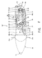
- the unit swing type engine 10 of the scooter type vehicle 1A of the first example is provided with a general forced-air-cooling-type four-stroke-cycle one cylinder engine main body 13.
- the engine main body 13 is constituted by a crank case 37 provided with a crank shaft, not shown, mainly extending in a width direction of the vehicle body and a cylinder assembly 39 forward inclined in a substantially horizontal direction towards a front side of the crank case 37 and having a central axis Z-Z arranged along a forward moving direction of the vehicle.
- the cylinder assembly 39 has a cylinder block 40 arranged in a front side of the crank case 37 and a cylinder head 41 arranged in a front side of the cylinder block 40.
- a piston not shown, is slidably installed within the cylinder block 40 and a valve moving apparatus, not shown, is installed in the cylinder head 41.
- the engine main body 13 may be a two-stroke-cycle engine, a multi-cylinder engine or a water-cooling-type engine. Further, in the case of the water-cooling-type engine, it is desirable that the radiator is arranged at a position with which a running wind is easily brought into contact, for example, a forward portion 42a of the head pipe 3 and a front portion 42b of the downtube 4 below the head pipe 3.
- a general type exhaust apparatus 43 is provided for the unit swing type engine 10 and the exhaust apparatus 43 is composed of an exhaust pipe 45 and a muffler 46 connected to a downstream end of the exhaust pipe 45.
- the exhaust pipe 45 has a base end portion connected to an exhaust port 44 in a lower side within the cylinder head 41 and extending towards a lower portion opposite to the transmission case 14 of the unit swing type engine 10, that is, rearward along a right lower portion towards a vehicle moving direction in the present embodiment.
- the muffler 46 extends towards a rear oblique upper portion.
- a fuel injection type intake apparatus 47 is also disposed to the unit swing type engine 10.
- the intake apparatus 47 is provided, as main elements, with an air cleaner 48A sucking the external air so as to make it clean, a throttle body 49 adjusting a flow amount of the sucked external air (hereinafter, refer to an intake air), an injector 50 as a fuel injecting means for injecting a fuel into an intake passage 49a of the throttle body 49, a fuel pump 51 feeding, under pressure, the fuel in the fuel tank 9A to the injector 50 and others.
- a flow amount of the intake air is adjusted by opening and closing a throttle valve 52 disposed in the intake passage 49a, and the opening and closing operation thereof is performed by the throttle grip 20a connected through a throttle cable 53 extending from the throttle body 49.
- the air cleaner 48A and the throttle body 49 are connected by a suction pipe 54, and the throttle body 49 and an intake port 55 in an upper side within the cylinder head 41 are connected by an intake pipe 56. Then, the suction pipe 54 and the intake pipe 56 constitute an intake passage connecting the intake port 55 to the air cleaner 48.
- the fuel tank 9A and the fuel pump 51, as well as the fuel pump 51 and the injector 50, are connected to each other by means fuel hoses 57.
- an amount, a timing and the like of the fuel injection performed by the injector 50 are electronically controlled by a controller 58.
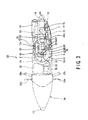
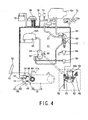
- a fuel injection system will be explained hereunder with reference to Fig. 4 .
- the fuel injection system is composed of a sensor unit, a control unit and an injection unit.
- the sensor unit is disposed for obtaining data necessary for determining and correcting a basic injection amount of the fuel and is provided with an intake pressure sensor 59 for detecting an intake pressure in the intake passage 49a of the throttle body 49, a signal generator 60 (a rotational number sensor) for detecting a rotational number of the crank shaft, a cam position sensor 62 for detecting a position (a valve timing) of a cam shaft 61 in the cylinder head 41 and a throttle position sensor 63 for detecting an opening degree of the throttle valve 52 in the intake passage 49a, in order to determine an amount of injection.
- an intake pressure sensor 59 for detecting an intake pressure in the intake passage 49a of the throttle body 49
- a signal generator 60 for detecting a rotational number of the crank shaft
- a cam position sensor 62 for detecting a position (a valve timing) of a cam shaft 61 in the cylinder head 41
- a throttle position sensor 63 for
- an atmospheric pressure sensor 64 for detecting an atmospheric pressure
- an intake temperature sensor 65 mounted to the air cleaner 48A and detecting a temperature of the intake air
- a plug seat temperature sensor 66 for detecting a temperature of an ignition plug mounting seat in the case that the engine main body 13 is of an air-cooling-type
- a water temperature sensor 67 mounted to the radiator 42 and detecting a temperature of a cooling water in the case that the engine main body 13 is of a water-cooling-type.
- the injection unit is composed of the fuel pump 51, the injector 50 and the like mentioned above. Furthermore, a fuel filter 68 for removing foreign matters within the fuel is provided in an upstream side of the fuel pump 51.
- the fuel pump 51 and the fuel filter 68 are arranged outside the fuel tank 9A. However, the structure may be made such that the apparatus are installed within the fuel tank 9A.
- an excessive component of the fuel fed to the injector 50 through the operation of the fuel pump 50 is returned to the fuel tank 9A by a pusher regulator 69.
- a cut sensor 70, a fuel pump relay 71 and the like are provided so as to be connected to the controller 58.
- a battery 72 is connected to the controller 58 and an electric power is supplied thereto, and further, the controller 58 is also connected to a combination meter 73 so as to indicate a remaining amount of the fuel, an alarm with respect to the fuel injecting system and the like on a meter panel 73a.
- the air cleaner 48A constituting the intake apparatus 47 is arranged on the transmission case 14 of the unit swing type engine 10, and the throttle body 49 provided with the injector 50 is arranged on the cylinder block 40 disposed in an obliquely front portion thereof.
- the air cleaner 48A, the throttle body 49, and the suction pipe 54 and the intake pipe 56 connecting these members are integrally formed and fixed to the upper surface of the engine 10 so as to be integrally swung.
- the fuel pump 51 is arranged above the suction pipe 54 and fixed to the rear frame 5, and the fuel hose 57 having an elasticity or flexibility extends from the fuel pump 51 to the fuel tank 9A and the injector 50. Then, the fuel hose 57 is fixed to a bottom surface of the article accommodation box 7A, for example, by a clamp 74 near the injector 50, thereby preventing the fuel hose 57 from coming off from the injector 50 when the injector 50 swings together with the engine 10.
- the controller 58 and the battery 72 are disposed to the side portion of the fuel tank 9A provided at the back of the accommodation box 7A adjacent to the fuel tank 9 in a parallel manner. Since the side portion of the fuel tank 9A at the back of the accommodation box 7A is apart from the engine 10 and the periphery thereof is surrounded by the rear frame cover 30, it is hard for heat generated by the unit swing type engine 10 to be transmitted to the controller 58 if the controller 58 is arranged in this place, and water-proof and dust-proof characteristics are high, so that it is preferable to place the controller 58. Further, if the unit swing type engine 10 is provided with the water-cooling-type engine main body, the engine is disposed to the place apart from the radiator 42a and 42b, so that the controller 58 is less little affected by an exhaust heat discharged from the radiator.
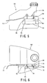
- Fig. 5 is an enlarged left side elevational view of the fuel tank 9A
- Fig. 6 is an enlarged plan view of the fuel tank 9A.
- a step portion 9a is formed, for example, on a left side surface of the fuel tank 9A to thereby form the space for placing the-controller 58 and the battery 72.
- a projection 75 for fixing is provided to the space corresponding to the shape of the bottom surface of the controller 58 and the battery 72 to position and fix the same.
- the controller 58 and the battery 72 are disposed in parallel to each other to make short the length of a wire 76 between both of the elements 58 and 72.
- a control cable 77 extends towards the injector 50 from the controller 58.
- the floor lower portion receiving chamber 32 formed between the rear leg shield 28 and the lower leg shield 29 may be employed as the other place where the heat from the unit swing type engine 10 and the radiators 42a and 42b is hard to be transmitted and the conditions for arranging the controller 58 having high water-proof and dust-proof characteristics are satisfied.
- the controller 78 is arranged within the floor lower portion receiving chamber 32.
- the intake apparatus 47 is arranged between the unit swing type engine 10 and the accommodation box 7A, and the bottom surface thereof is formed so as to provide such a shape that the rear cushion unit 15 is not brought into contact with any of the unit swing type engine 10 and the intake apparatus 47 in a state of being most compressed, due to a vertical swing motion thereof.
- the bottom surface of the article accommodation box 7A is formed in an obliquely forward descending direction so as to be substantially in parallel to a line connecting two points at the highest position of an upper profile 79 of the unit swing type engine 10 and the intake apparatus 47 in a state that the rear cushion unit 15 is most compressed, that is, in the present embodiment, a line X-X connecting an upper portion of the cylinder head 41 and an upper portion of the throttle body 49 or a line X'-X' connecting an upper portion of the cylinder head 41 and an upper portion of the air cleaner 48.
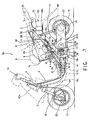
- Figs. 7 and 8 show a first example of a second embodiment of a scooter type vehicle 1J to which the present invention is applicable, in which Fig. 7 is a left side elevational view showing an internal structure of the scooter type vehicle 1J and Fig. 8 is a schematic plan view of the scooter type vehicle 1J shown in Fig. 7 .
- the same reference numerals are attached to the corresponding elements as those of the scooter type vehicle 1A shown in the first embodiment of FIGs. 1 to 3 , and the description thereof is hence omitted herein as occasion demands.
- the scooter type vehicle 1J basically has the same structure as that of the scooter type vehicle 1A shown in the first embodiment. However, the structure of this example is different in the following points.
- a fuel tank 9J is moved, from a rear portion of an article accommodation box 7J, to an independent space below the step floor 31 in which the floor lower portion receiving chamber 32 is inherently provided, and as is described at a time of explaining the structure of the fuel injection system, the fuel pump 51 is installed in the fuel tank 9J. Further, an oil supply lid 92 is disposed to the step floor 31 directly above an oil supply port 91 of the fuel tank 9J so as to be freely opened and closed.
- the fuel tank 9J is provided to the lower portion of the step floor 31, so that the accommodation box 7J extends rearward and the capacity thereof can be increased. Further, at a time of extending the accommodation box 7J rearward, an upper profile 79 of an air cleaner 48J is overlapped (OL) with a bottom surface of the accommodation box 7J in a side elevational view in a state that the rear cushion unit 15 is most compressed.
- an escaping portion 93 towards the above portion of the bottom surface of the accommodation box 7J may be recessed. As a result, even in the case that a stroke amount of the rear cushion unit 15 is sufficiently secured, a capacity of the accommodation box 7J is not largely reduced.
- the bottom surface of the accommodation box 7J is formed in a mount shape in a side elevational view, the helmet 6 is received in a front portion of an apex thereof in a forward descending state, and the helmet take-out space 80 can be formed below the rear lower portion of the helmet 6 by setting the apex to the front side from the rear lower portion of the helmet 6, so that the helmet 6 can be easily taken out by a rider inserting his (her) hand 81 into the helmet take-out space 80.
- the shape of the article accommodation box 7J of this example may be applicable to the conventional structure of the vehicle using the carburetor (not shown).
- a rear receiving chamber 94 is formed at the back of the accommodation box 7J as a place where the heat from the unit swing type engine 10 and the radiators 42a and 42b is hard to be transmitted and high water-proof and dust-proof characteristics can be obtained, in such a manner as to be adjacent to the combination lamp 35, and the controller 58 and the battery 72 are disposed in the rear receiving chamber 94.
- the rear receiving chamber 94 is closed by a maintenance lid 95 which is freely opened and closed.
- the scooter type vehicle 1J has a structure in which the throttle body 49 and the intake pipe 56 are arranged so that the axis Y-Y in the fuel injecting direction of the injector 50 substantially vertically crosses the central axis Z-Z of the cylinder assembly 39, whereby the fuel injected from the injector 50 is directed inside the intake port 55 to a side having a large curvature and having a large flow amount of the mixture gas.
- the unit swing type engine 10 may be also suspended either at an upper position or a lower position.
- Figs. 9 and 10 show a second example of the second embodiment of a scooter type vehicle 1L to which the present invention is applicable, in which Fig. 9 is a left side elevational view showing an internal structure of the scooter type vehicle 1L and Fig. 10 is a schematic plan view of the scooter type vehicle 1L shown in Fig. 9 .
- the same reference numerals are attached to the same elements as those of the scooter type vehicle 1J shown in the first example of the present second embodiment, and the description thereof is hence omitted herein as occasion demands.
- the scooter type vehicle 1L has a structure in which an air cleaner 48L is arranged in a rear left side of an article accommodation box 7L corresponding to a portion of a space at the back of the accommodation box 7L formed by placing a fuel tank 9L in the lower portion of the step floor 31. Then, the suction pipe 54 extends towards the throttle body 49 from a lower portion of the air cleaner 48L to thereby provide a substantially linear shape.
- the throttle body 49 integrally swings together with the unit swing type engine 10 in a vertical direction, and the air cleaner 48L is fixed to the vehicle body side, and for this reason, the suction pipe 54 can be formed by a material having an elasticity or a material having a bellows structure.
- An intake resistance is reduced by arranging the suction pipe 54 in a substantially liner manner, and an engine output can be improved. Furthermore, since the air cleaner 48L is arranged at the back of the accommodation box 7L, not on the transmission case 14, it is possible to increase a freedom for determining (designing) a lower line 30a of the rear frame cover 30 surrounding the right and left portions of the rear frame 5.
- the suction pipe 54 is arranged so as to pass through the portion between the right and left engine suspending bosses 11a and the suspending bracket 12a.
- the other portions that is, a right side of the air cleaner 48L, can be utilized as a rearward extending portion 97 of the article accommodation box 7L, and therefore, a long article 98 can be accommodated.
- the controller 58 is arranged at a portion between the air cleaner 48L and the rearward extending portion 97 of the accommodation box 7L as a place where the heat from the engine 10 and the radiators 42a and 42b is hard to be transmitted and the water-proof and dust-proof characteristics become high.
- the helmet take-out space 80 is formed between the rearward extending portion 97 and the rear portion of the helmet 6, the helmet 6 can be easily taken out by a rider by inserting his (her) hand 81 into the helmet take-out space 80.
- the helmet 6 can be easily taken out and the long article can be accommodated therein, and this structure may be applicable to a vehicle using the carburetor (not shown) of a prior art.
Description
- The present invention relates to a scooter type vehicle, and more particularly to a scooter type vehicle provided with a fuel injection type intake apparatus.
- In a prior art, there has been provided a structure using a carburetor as means for supplying an air-fuel mixture to an engine (
EP 0 806 557 A - Accordingly, in recent years, there has been popularly proposed an engine provided with a fuel injection type intake apparatus which detects a throttle opening degree, an engine rotational number, an engine temperature, an external air temperature, an external air pressure and the like by a sensor and then processes the information mentioned above by a computer so as to directly inject a required fuel, of an amount which is most suitable at that time, to an intake passage of the engine.
- The fuel injection type intake apparatus has advantages such as that a combustion efficiency is improved and an output can be improved. However, a fuel consumption amount is reduced since only a minimum required amount of fuel is injected, an amount of harmful objects in an exhaust gas is reduced and the like, so that the fuel injection type intake apparatus has been generally employed in an automobile.
- However, in the case of a compact vehicle such as a scooter type vehicle, since a. lot of parts are provided within a limited narrow space, it is necessary to sufficiently consider arrangement of a controller having a computer installed, a fuel pump and various kinds of sensors in the case that a fuel injection type intake apparatus is newly provided.
- In particular, since most of the scooter type vehicles have structures which are exposed to an external environment, it is particularly important, in the case of desiring an accurate control, to arrange a controller having a weak point with respect to heat, water, dust or the like with a maximum care.
- The scooter type vehicle is frequently provided with a unit swing type engine which swings vertically together with a rear wheel as a drive wheel, and the fuel injection type intake apparatus is in many cases provided on an upper surface of the unit swing type engine so as to be integrally swung therewith. Accordingly, a position of a bottom surface of an article accommodation (storage) box arranged above the unit swing type engine is restricted.
- Although a capacity of the article accommodation box can be increased at a certain degree by reducing an amount of stroke of a rear cushion unit elastically supporting the unit swing type engine, a rider's feeling is deteriorated.
-
FR 2 698 603 A1 - The present invention is made by taking the matters mentioned above into consideration, and an object of the present invention is to provide a scooter type vehicle capable of sufficiently securing a capacity or inner volume of an article accommodation box or chamber without deteriorating a rider's feeling.
- This object and other objects can be achieved, according to the present invention by a scooter-type vehicle as defined in claim 1 or in
claim 2. - That is, the scooter type vehicle of the present invention comprises:
- a unit swing type engine provided with an engine body having a cylinder assembly forward inclined in a substantially horizontal direction and having a central axis arranged along a longitudinal direction of a vehicle body and a transmission case rearward extending from one side of the engine body and supporting a rear wheel to a rear end thereof, swingably pivoted to a vehicle body frame and flexibly supported to a vehicle body frame through a cushion unit;
- a fuel injection type intake apparatus comprising a throttle body connected to an intake port of the cylinder assembly, an air cleaner connected to the throttle body, fuel injecting means and a controller for controlling a fuel injection amount of the fuel injecting means; and
- an accommodation box arranged above the unit swing type engine, and in such scooter type vehicle:
- a bottom surface of a frontal area of the accommodation box is formed to be downwardly protruded in a side view, a helmet is accommodated in front of the top portion of the bottom surface of the accommodation box,
- a fuel tank is arranged in a vehicle body arranged in front of the unit swing type engine, the air cleaner is arranged above the unit swing type engine, and an engine suspending boss disposed on the upper surface of the swing unit type engine, the throttle body and the fuel injection means are disposed below the accommodation box and behind the downwardly protruded portion thereof. Also a carburetor may be used, taking the place of the throttle body and the fuel injection means.
- The nature and further characteristic features of the present invention will be made more clear from the following descriptions made with reference to the accompanying drawings.
- In the accompanying drawings:
-
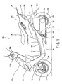
Fig. 1 is a left side elevational view showing a first embodiment of a scooter type vehicle; -
Fig. 2 is a left side elevational view showing an-internal structure of the scooter type vehicle shown inFig. 1 ; -
Fig. 3 is a schematic plan view of the scooter type vehicle shown inFigs. 1 and2 ; -
Fig. 4 is a schematic view of a fuel injection system for the scooter type vehicle ofFig. 1 ; -
Fig. 5 is an enlarged left side elevational view of a fuel tank of the scooter type vehicle ofFig. 1 ; -
Fig. 6 is an enlarged plan view of the fuel tank; -
Fig. 7 is a left side elevational view showing an internal structure of a first example of a second embodiment of the scooter type vehicle to which the present invention is applicable; -
Fig. 8 is a schematic plan view of the scooter type vehicle shown inFig. 7 ; -
Fig. 9 is a left side elevational view shoving an internal structure of a second example of the second embodiment of the scooter type vehicle to which the present invention is applicable; -
Fig. 10 is a schematic plan view of the scooter type vehicle shown inFig. 9 : - Preferred embodiments of the present invention will be described hereunder with reference to various examples shown in the accompanying drawings.
- A first embodiment of a scooter type vehicle not being part of the invention will be first described with reference to
Figs. 1 to 6 . - As shown in
Figs. 1 to 3 , ascooter type vehicle 1A has avehicle body frame 2. Thevehicle body frame 2 is provided with a head pipe 3 in a forefront portion thereof and is constituted by adowntube 4 extending from a rear lower portion of the head pipe 3 towards a rear downward portion and extending in a substantially horizontal direction towards a rear portion from an intermediate portion thereof, and a pair of right and leftrear frames 5 extending towards a rear upper portion from a rear end side of thedowntube 4. - An article accommodation (storage)
box 7A for accommodating (storing) an article such ashelmet 6 is disposed above therear frames 5. Further, adriver seat 8 commonly serving as a lid for the article accommodation box-7A is placed above thebox 7A in a manner to be freely opened and closed, and afuel tank 9A is arranged in a rear portion of theaccommodation box 7A. - A unit
swing type engine 10 is arranged in a substantially central lower portion of therear frames 5. A pair of right and leftengine suspending bosses 11a provided in parallel in a width direction of the vehicle body are provided on an upper surface of the unitswing type engine 10, and theengine suspending bosses 11a are pivoted to a pair of right and leftengine suspending brackets 12a provided in a substantially central lower portion of therear frames 5, so that the unitswing type engine 10 is swingably supported. In this case, as shown by a double-dotted chain line inFig. 2 , the structure may be made such thatengine suspending bosses 11b are provided on a lower surface of the unitswing type engine 10 and the unitswing type engine 10 is pivoted toengine suspending brackets 12b provided in a rear end lower portion of thedowntube 4. - The unit
swing type engine 10 is integrally provided with an enginemain body 13 and a transmittingcase 14 rearward extending from a left side toward one side of the enginemain body 13, that is, a forward moving direction of the vehicle in the present embodiment. Thetransmission case 14 commonly serves as a swing arm and is elastically supported to therear frame 5 by arear cushion unit 15. Arear wheel 16 as a driving wheel is pivoted to a rear end of thetransmission case 14. - A
front fork 18 rotatably supporting afront wheel 17, ahandle bar 19 and the like are provided in the head pipe 3.Grips handle bar 19, in which theright grip 20a in a forward moving direction of the vehicle serves as a throttle grip. Further, brake levers 21a and 21b are provided in front sides of both of thegrips brake apparatus front wheel 17 and therear wheel 16 viabrake wires front wheel 17 is rotatably steered to right and left by thehandle bar 19. - Furthermore, the
vehicle frame 2 is surrounded by avehicle body cover 26 which constitutes an outer appearance of the vehicle body. Thevehicle body cover 26 is structured by combining a plurality of cover elements. The cover elements are particularly constituted by, for example, afront leg shield 27, arear leg shield 28, alower leg shield 29, arear frame cover 30 and others. - A portion between the
driver seat 8 and the head pipe 3 is largely curved downward, and therear leg shield 28 provided with astep floor 31 on which a rider puts both feet is arranged in a bottom portion thereof. Therear leg shield 28 is arranged so as to cover a horizontal portion of thedowntube 4 from the above and is fixed to thedowntube 4. Further, thelower leg shield 29 is arranged below therear leg shield 28 so as to cover the horizontal portion of thedowntube 4 from the below. A floor lowerportion receiving chamber 32 is disposed in a space formed between therear leg shield 28 and thelower leg shield 29, so that it is possible to access an interior portion thereof by freely opening and closing alid 33 provided to thestep floor 31. Furthermore, thefront leg shield 27 standing upward from a front portion of therear leg shield 28 is arranged so as to cover front and rear portions of the head pipe 3 and is fixed to a stand-up portion of thedowntube 4, and ahead light 34 is disposed in a front lower portion of thefront leg shield 27. - On the contrary, the
rear frame cover 30, for example, formed in a laterally separated manner or in an integral manner is provided in a periphery of therear frame 5 so as to surround the right and left portions of therear frame 5. Further, acombination lamp 35 is provided at a rear end of therear frame cover 30. Arear carrier 36 is provided above thecombination lamp 35. In this case, the cover element is molded by a plastic resin material, for example, a PP resin, an ABS resin or the like. - The unit
swing type engine 10 of thescooter type vehicle 1A of the first example is provided with a general forced-air-cooling-type four-stroke-cycle one cylinder enginemain body 13. The enginemain body 13 is constituted by acrank case 37 provided with a crank shaft, not shown, mainly extending in a width direction of the vehicle body and acylinder assembly 39 forward inclined in a substantially horizontal direction towards a front side of thecrank case 37 and having a central axis Z-Z arranged along a forward moving direction of the vehicle. - Further, the
cylinder assembly 39 has acylinder block 40 arranged in a front side of thecrank case 37 and acylinder head 41 arranged in a front side of thecylinder block 40. A piston, not shown, is slidably installed within thecylinder block 40 and a valve moving apparatus, not shown, is installed in thecylinder head 41. - In this example, the engine
main body 13 may be a two-stroke-cycle engine, a multi-cylinder engine or a water-cooling-type engine. Further, in the case of the water-cooling-type engine, it is desirable that the radiator is arranged at a position with which a running wind is easily brought into contact, for example, aforward portion 42a of the head pipe 3 and afront portion 42b of thedowntube 4 below the head pipe 3. - A general
type exhaust apparatus 43 is provided for the unitswing type engine 10 and theexhaust apparatus 43 is composed of anexhaust pipe 45 and amuffler 46 connected to a downstream end of theexhaust pipe 45. Theexhaust pipe 45 has a base end portion connected to anexhaust port 44 in a lower side within thecylinder head 41 and extending towards a lower portion opposite to thetransmission case 14 of the unitswing type engine 10, that is, rearward along a right lower portion towards a vehicle moving direction in the present embodiment. Themuffler 46 extends towards a rear oblique upper portion. - A fuel injection
type intake apparatus 47 is also disposed to the unitswing type engine 10. Theintake apparatus 47 is provided, as main elements, with anair cleaner 48A sucking the external air so as to make it clean, athrottle body 49 adjusting a flow amount of the sucked external air (hereinafter, refer to an intake air), aninjector 50 as a fuel injecting means for injecting a fuel into anintake passage 49a of thethrottle body 49, afuel pump 51 feeding, under pressure, the fuel in thefuel tank 9A to theinjector 50 and others. - A flow amount of the intake air is adjusted by opening and closing a
throttle valve 52 disposed in theintake passage 49a, and the opening and closing operation thereof is performed by thethrottle grip 20a connected through athrottle cable 53 extending from thethrottle body 49. - Furthermore, the
air cleaner 48A and thethrottle body 49 are connected by asuction pipe 54, and thethrottle body 49 and anintake port 55 in an upper side within thecylinder head 41 are connected by anintake pipe 56. Then, thesuction pipe 54 and theintake pipe 56 constitute an intake passage connecting theintake port 55 to the air cleaner 48. Thefuel tank 9A and thefuel pump 51, as well as thefuel pump 51 and theinjector 50, are connected to each other by meansfuel hoses 57. - Further, an amount, a timing and the like of the fuel injection performed by the
injector 50 are electronically controlled by acontroller 58. A fuel injection system will be explained hereunder with reference toFig. 4 . - With reference to
Fig. 4 , the fuel injection system is composed of a sensor unit, a control unit and an injection unit. The sensor unit is disposed for obtaining data necessary for determining and correcting a basic injection amount of the fuel and is provided with anintake pressure sensor 59 for detecting an intake pressure in theintake passage 49a of thethrottle body 49, a signal generator 60 (a rotational number sensor) for detecting a rotational number of the crank shaft, acam position sensor 62 for detecting a position (a valve timing) of acam shaft 61 in thecylinder head 41 and athrottle position sensor 63 for detecting an opening degree of thethrottle valve 52 in theintake passage 49a, in order to determine an amount of injection. - Furthermore, in order to correct the amount of injection, there are provided with an
atmospheric pressure sensor 64 for detecting an atmospheric pressure, anintake temperature sensor 65 mounted to theair cleaner 48A and detecting a temperature of the intake air, a plugseat temperature sensor 66 for detecting a temperature of an ignition plug mounting seat in the case that the enginemain body 13 is of an air-cooling-type, awater temperature sensor 67 mounted to theradiator 42 and detecting a temperature of a cooling water in the case that the enginemain body 13 is of a water-cooling-type. Then, the data obtained by the sensor units are transmitted to thecontroller 58 as a control portion, thus determining the amount and the timing of the fuel injection. - Furthermore, data about the amount and the timing of the fuel injection determined by the
controller 58 are transmitted to the injection unit to control each of the apparatus or devices. The injection unit is composed of thefuel pump 51, theinjector 50 and the like mentioned above. Furthermore, afuel filter 68 for removing foreign matters within the fuel is provided in an upstream side of thefuel pump 51. In this embodiment, with reference toFig. 4 , thefuel pump 51 and thefuel filter 68 are arranged outside thefuel tank 9A. However, the structure may be made such that the apparatus are installed within thefuel tank 9A. - Further, an excessive component of the fuel fed to the
injector 50 through the operation of thefuel pump 50 is returned to thefuel tank 9A by apusher regulator 69. Then, as an auxiliary device for controlling the injection unit, for example, acut sensor 70, afuel pump relay 71 and the like are provided so as to be connected to thecontroller 58. - Furthermore, a
battery 72 is connected to thecontroller 58 and an electric power is supplied thereto, and further, thecontroller 58 is also connected to acombination meter 73 so as to indicate a remaining amount of the fuel, an alarm with respect to the fuel injecting system and the like on ameter panel 73a. - Hereunder, a description will be given of an arrangement of the
intake apparatus 47. As shown inFigs. 2 and3 , theair cleaner 48A constituting theintake apparatus 47 is arranged on thetransmission case 14 of the unitswing type engine 10, and thethrottle body 49 provided with theinjector 50 is arranged on thecylinder block 40 disposed in an obliquely front portion thereof. In this case, theair cleaner 48A, thethrottle body 49, and thesuction pipe 54 and theintake pipe 56 connecting these members are integrally formed and fixed to the upper surface of theengine 10 so as to be integrally swung. - Further, the
fuel pump 51 is arranged above thesuction pipe 54 and fixed to therear frame 5, and thefuel hose 57 having an elasticity or flexibility extends from thefuel pump 51 to thefuel tank 9A and theinjector 50. Then, thefuel hose 57 is fixed to a bottom surface of thearticle accommodation box 7A, for example, by aclamp 74 near theinjector 50, thereby preventing thefuel hose 57 from coming off from theinjector 50 when theinjector 50 swings together with theengine 10. - Further, the
controller 58 and thebattery 72 are disposed to the side portion of thefuel tank 9A provided at the back of theaccommodation box 7A adjacent to the fuel tank 9 in a parallel manner. Since the side portion of thefuel tank 9A at the back of theaccommodation box 7A is apart from theengine 10 and the periphery thereof is surrounded by therear frame cover 30, it is hard for heat generated by the unitswing type engine 10 to be transmitted to thecontroller 58 if thecontroller 58 is arranged in this place, and water-proof and dust-proof characteristics are high, so that it is preferable to place thecontroller 58. Further, if the unitswing type engine 10 is provided with the water-cooling-type engine main body, the engine is disposed to the place apart from theradiator controller 58 is less little affected by an exhaust heat discharged from the radiator. -
Fig. 5 is an enlarged left side elevational view of thefuel tank 9A andFig. 6 , is an enlarged plan view of thefuel tank 9A. As shown inFigs. 5 and 6 , astep portion 9a is formed, for example, on a left side surface of thefuel tank 9A to thereby form the space for placing the-controller 58 and thebattery 72. Further, aprojection 75 for fixing is provided to the space corresponding to the shape of the bottom surface of thecontroller 58 and thebattery 72 to position and fix the same. - The
controller 58 and thebattery 72 are disposed in parallel to each other to make short the length of awire 76 between both of theelements control cable 77 extends towards theinjector 50 from thecontroller 58. In this case, the floor lowerportion receiving chamber 32 formed between therear leg shield 28 and thelower leg shield 29 may be employed as the other place where the heat from the unitswing type engine 10 and theradiators controller 58 having high water-proof and dust-proof characteristics are satisfied. In the example shown inFigs. 2 and3 with double-dotted chain line, thecontroller 78 is arranged within the floor lowerportion receiving chamber 32. - In this case, a large accommodation capacity (inner volume) is required for the
accommodation box 7A arranged above the unitswing type engine 10. Further, theintake apparatus 47 is arranged between the unitswing type engine 10 and theaccommodation box 7A, and the bottom surface thereof is formed so as to provide such a shape that therear cushion unit 15 is not brought into contact with any of the unitswing type engine 10 and theintake apparatus 47 in a state of being most compressed, due to a vertical swing motion thereof. - In particular, the bottom surface of the
article accommodation box 7A is formed in an obliquely forward descending direction so as to be substantially in parallel to a line connecting two points at the highest position of anupper profile 79 of the unitswing type engine 10 and theintake apparatus 47 in a state that therear cushion unit 15 is most compressed, that is, in the present embodiment, a line X-X connecting an upper portion of thecylinder head 41 and an upper portion of thethrottle body 49 or a line X'-X' connecting an upper portion of thecylinder head 41 and an upper portion of the air cleaner 48. -
Figs. 7 and8 show a first example of a second embodiment of ascooter type vehicle 1J to which the present invention is applicable, in whichFig. 7 is a left side elevational view showing an internal structure of thescooter type vehicle 1J andFig. 8 is a schematic plan view of thescooter type vehicle 1J shown inFig. 7 . In this case, the same reference numerals are attached to the corresponding elements as those of thescooter type vehicle 1A shown in the first embodiment ofFIGs. 1 to 3 , and the description thereof is hence omitted herein as occasion demands. - As shown in
Figs. 7 and8 , thescooter type vehicle 1J basically has the same structure as that of thescooter type vehicle 1A shown in the first embodiment. However, the structure of this example is different in the following points. - At first, a
fuel tank 9J is moved, from a rear portion of anarticle accommodation box 7J, to an independent space below thestep floor 31 in which the floor lowerportion receiving chamber 32 is inherently provided, and as is described at a time of explaining the structure of the fuel injection system, thefuel pump 51 is installed in thefuel tank 9J. Further, anoil supply lid 92 is disposed to thestep floor 31 directly above anoil supply port 91 of thefuel tank 9J so as to be freely opened and closed. - Then, the
fuel tank 9J is provided to the lower portion of thestep floor 31, so that theaccommodation box 7J extends rearward and the capacity thereof can be increased. Further, at a time of extending theaccommodation box 7J rearward, anupper profile 79 of anair cleaner 48J is overlapped (OL) with a bottom surface of theaccommodation box 7J in a side elevational view in a state that therear cushion unit 15 is most compressed. Here, in the case that theair cleaner 48J and the bottom surface of theaccommodation box 7J are interfere with each other, an escapingportion 93 towards the above portion of the bottom surface of theaccommodation box 7J may be recessed. As a result, even in the case that a stroke amount of therear cushion unit 15 is sufficiently secured, a capacity of theaccommodation box 7J is not largely reduced. - Further, the bottom surface of the
accommodation box 7J is formed in a mount shape in a side elevational view, thehelmet 6 is received in a front portion of an apex thereof in a forward descending state, and the helmet take-outspace 80 can be formed below the rear lower portion of thehelmet 6 by setting the apex to the front side from the rear lower portion of thehelmet 6, so that thehelmet 6 can be easily taken out by a rider inserting his (her)hand 81 into the helmet take-outspace 80.
Further, the shape of thearticle accommodation box 7J of this example may be applicable to the conventional structure of the vehicle using the carburetor (not shown). - Further, in this example, a
rear receiving chamber 94 is formed at the back of theaccommodation box 7J as a place where the heat from the unitswing type engine 10 and theradiators combination lamp 35, and thecontroller 58 and thebattery 72 are disposed in therear receiving chamber 94. In this example, therear receiving chamber 94 is closed by amaintenance lid 95 which is freely opened and closed. - It is possible to take out the
respective wires 76 in the same direction by arranging thecontroller 58, and thebattery 72 in adjacent to thecombination lamp 35, thus simplifying the arrangement of the wires. Furthermore, since thecontroller 58 and thebattery 72 can be disposed in the therear receiving chamber 94, both theapparatus maintenance lid 95. - Further, the
scooter type vehicle 1J has a structure in which thethrottle body 49 and theintake pipe 56 are arranged so that the axis Y-Y in the fuel injecting direction of theinjector 50 substantially vertically crosses the central axis Z-Z of thecylinder assembly 39, whereby the fuel injected from theinjector 50 is directed inside theintake port 55 to a side having a large curvature and having a large flow amount of the mixture gas. - In this example, the unit
swing type engine 10 may be also suspended either at an upper position or a lower position. -
Figs. 9 and10 show a second example of the second embodiment of a scooter type vehicle 1L to which the present invention is applicable, in whichFig. 9 is a left side elevational view showing an internal structure of the scooter type vehicle 1L andFig. 10 is a schematic plan view of the scooter type vehicle 1L shown inFig. 9 . In this example, the same reference numerals are attached to the same elements as those of thescooter type vehicle 1J shown in the first example of the present second embodiment, and the description thereof is hence omitted herein as occasion demands. - As shown in
Figs. 9 and10 , the scooter type vehicle 1L has a structure in which anair cleaner 48L is arranged in a rear left side of anarticle accommodation box 7L corresponding to a portion of a space at the back of theaccommodation box 7L formed by placing afuel tank 9L in the lower portion of thestep floor 31. Then, thesuction pipe 54 extends towards thethrottle body 49 from a lower portion of the air cleaner 48L to thereby provide a substantially linear shape. In this case, thethrottle body 49 integrally swings together with the unitswing type engine 10 in a vertical direction, and theair cleaner 48L is fixed to the vehicle body side, and for this reason, thesuction pipe 54 can be formed by a material having an elasticity or a material having a bellows structure. - An intake resistance is reduced by arranging the
suction pipe 54 in a substantially liner manner, and an engine output can be improved. Furthermore, since theair cleaner 48L is arranged at the back of theaccommodation box 7L, not on thetransmission case 14, it is possible to increase a freedom for determining (designing) alower line 30a of therear frame cover 30 surrounding the right and left portions of therear frame 5. - Here, in the case that the unit
swing type engine 10 is suspended to theengine suspending bracket 12a provided in therear frame 5 by a pair of right and leftengine suspending bosses 11a parallelly disposed on an upper surface thereof, thesuction pipe 54 is arranged so as to pass through the portion between the right and leftengine suspending bosses 11a and the suspendingbracket 12a. - Still furthermore, since only a certain portion of the space at the rear of the
accommodation box 7L can be utilized for arranging theair cleaner 48L, the other portions, that is, a right side of theair cleaner 48L, can be utilized as a rearward extendingportion 97 of thearticle accommodation box 7L, and therefore, along article 98 can be accommodated. Further, thecontroller 58 is arranged at a portion between theair cleaner 48L and the rearward extendingportion 97 of theaccommodation box 7L as a place where the heat from theengine 10 and theradiators - Furthermore, since the helmet take-out
space 80 is formed between the rearward extendingportion 97 and the rear portion of thehelmet 6, thehelmet 6 can be easily taken out by a rider by inserting his (her)hand 81 into the helmet take-outspace 80. - In this example, according to the shape of the
accommodation box 7L, thehelmet 6 can be easily taken out and the long article can be accommodated therein, and this structure may be applicable to a vehicle using the carburetor (not shown) of a prior art.
Claims (5)
- A scooter-type vehicle (1) which comprises: a unit swing type engine (10) provided with an engine body (13) having a cylinder assembly (39) forward inclined in a substantially horizontal direction and having a central axis (Z-Z) arranged along a longitudinal direction of a vehicle body and a transmission case (14) rearward extending from one side of the engine body (13) and supporting a rear wheel (16) to a rear end thereof, swingably pivoted to a vehicle body frame (2) and flexibly supported to the vehicle body frame (2) through a cushion unit (15); a fuel injection type intake apparatus (47) comprising a throttle body (49) connected to an intake port (55) of the cylinder assembly (39), an air cleaner (48) connected to the throttle body (49), fuel injecting means (50) and a controller (58) for controlling a fuel injection amount of the fuel injecting means (50); and an accommodation box (7) arranged above the unit swing type engine (10):
characterized in that a fuel tank (9) is arranged to the engine body (13) in front of the swing unit type engine (10), the air cleaner (48) is arranged above the swing unit type engine (10), the bottom surface of a frontal area of the accommodation box (7) is formed to be downwardly protruded in a side view, a helmet (6) is accommodated in front of the top portion of the bottom surface of the accommodation, box (7) and the engine suspending boss (11a) disposed on the upper surface of the swing unit type engine (10), the throttle body (49) and the fuel injection means (50) are disposed below the accommodation box (7) and behind the downwardly protruded portion thereof. - A scooter-type vehicle (1) which comprises: a unit swing type engine (10) provided with an engine body (13) having a cylinder assembly (39) forward inclined in a substantially horizontal direction and having a central axis (Z-Z) arranged along a longitudinal direction of a vehicle body and a transmission case (14) rearward extending from one side of the engine body (13) and supporting a rear (16) wheel to a rear end thereof, swingably pivoted to a vehicle body frame (2) and flexibly supported to the vehicle body frame (2) through a cushion unit (15), a carburetor connected to an intakeport (55) of the cylinder assembly (39); and an accommodation box (7) arranged above the unit swing type engine (10) wherein a fuel tank (9) is arranged to the engine body (13) in front of the swing unit type engine (10), and the bottom surface of a frontal area of the accommodation box (7) is formed to be downwardly protruded in a side view, a helmet (6) is accommodated in front of the top portion of the bottom surface of the accommodation box (7),
characterized in that
the air cleaner (48) is arranged above the swing unit type engine (10), and the engine suspending boss (11a) disposed on the upper surface of the swing unit type engine (10) and the carburetor are disposed below the accommodation box (7), and behind the downwardly protruded portion thereof. - The scooter type vehicle according to claim 1 or 2.
wherein the suspending boss (11a) provided to the unit swing type engine (10) and the vehicle body frame (2) are pivoted by an engine suspension bracket (12a) so that the swing unit type engine (10) is swingable, and a helmet take-out space (80) is formed to a vehicle rear side portion of the bottom surface of the accommodation box (7). - The scooter type vehicle according to any one of claims 1 to 3,
wherein the fuel tank (9) is provided with a fuel pump on a left side of the vehicle in the vehicle advancing direction. - The scooter type vehicle according to any one of claims 1, 2 and 4,
wherein the engine body is constructed as a water-cool type engine, and a radiator for cooling the engine body is disposed below a head pipe supporting a front wheel of the vehicle.
Applications Claiming Priority (2)
| Application Number | Priority Date | Filing Date | Title |
|---|---|---|---|
| JP2000029599A JP4423724B2 (en) | 2000-02-07 | 2000-02-07 | Scooter type vehicle |
| EP01102607A EP1122159B1 (en) | 2000-02-07 | 2001-02-06 | Scooter-type vehicle |
Related Parent Applications (1)
| Application Number | Title | Priority Date | Filing Date |
|---|---|---|---|
| EP01102607A Division EP1122159B1 (en) | 2000-02-07 | 2001-02-06 | Scooter-type vehicle |
Publications (3)
| Publication Number | Publication Date |
|---|---|
| EP1752369A2 EP1752369A2 (en) | 2007-02-14 |
| EP1752369A3 EP1752369A3 (en) | 2007-03-21 |
| EP1752369B1 true EP1752369B1 (en) | 2009-11-11 |
Family
ID=18554834
Family Applications (4)
| Application Number | Title | Priority Date | Filing Date |
|---|---|---|---|
| EP06019473A Expired - Lifetime EP1752369B1 (en) | 2000-02-07 | 2001-02-06 | Scooter-type vehicle |
| EP06019474A Expired - Lifetime EP1752370B1 (en) | 2000-02-07 | 2001-02-06 | Scooter-type vehicle |
| EP01102607A Expired - Lifetime EP1122159B1 (en) | 2000-02-07 | 2001-02-06 | Scooter-type vehicle |
| EP06019472A Expired - Lifetime EP1752368B1 (en) | 2000-02-07 | 2001-02-06 | Scooter-type vehicle |
Family Applications After (3)
| Application Number | Title | Priority Date | Filing Date |
|---|---|---|---|
| EP06019474A Expired - Lifetime EP1752370B1 (en) | 2000-02-07 | 2001-02-06 | Scooter-type vehicle |
| EP01102607A Expired - Lifetime EP1122159B1 (en) | 2000-02-07 | 2001-02-06 | Scooter-type vehicle |
| EP06019472A Expired - Lifetime EP1752368B1 (en) | 2000-02-07 | 2001-02-06 | Scooter-type vehicle |
Country Status (4)
| Country | Link |
|---|---|
| EP (4) | EP1752369B1 (en) |
| JP (1) | JP4423724B2 (en) |
| DE (4) | DE60139647D1 (en) |
| ES (4) | ES2327771T3 (en) |
Cited By (1)
| Publication number | Priority date | Publication date | Assignee | Title |
|---|---|---|---|---|
| CN102837776A (en) * | 2011-06-23 | 2012-12-26 | 光阳工业股份有限公司 | Scooter motorcycle structure |
Families Citing this family (41)
| Publication number | Priority date | Publication date | Assignee | Title |
|---|---|---|---|---|
| JP4690364B2 (en) * | 2001-09-27 | 2011-06-01 | ヤマハ発動機株式会社 | Fuel hose mounting structure for motorcycle fuel injection engines |
| JP4999822B2 (en) * | 2001-09-27 | 2012-08-15 | ヤマハ発動機株式会社 | Motorcycle |
| JP4007788B2 (en) * | 2001-10-22 | 2007-11-14 | ヤマハ発動機株式会社 | Scooter type motorcycle fuel supply system |
| JP4021339B2 (en) * | 2003-02-12 | 2007-12-12 | 本田技研工業株式会社 | Fuel supply system for motorcycles |
| JP4673562B2 (en) * | 2004-03-01 | 2011-04-20 | 本田技研工業株式会社 | Motorcycle storage box and fuel tank structure |
| JP4529642B2 (en) * | 2004-11-02 | 2010-08-25 | スズキ株式会社 | Scooter type motorcycle |
| JP4580314B2 (en) * | 2005-08-31 | 2010-11-10 | 本田技研工業株式会社 | Motorcycle |
| CN1970380B (en) * | 2005-11-25 | 2011-06-29 | 雅马哈发动机株式会社 | Battery jar accomodation structure for engine |
| JP4954613B2 (en) * | 2006-05-26 | 2012-06-20 | 本田技研工業株式会社 | Scooter-type vehicle intake system |
| JP5072328B2 (en) * | 2006-11-22 | 2012-11-14 | 本田技研工業株式会社 | Motorcycle |
| JP2008239143A (en) | 2007-02-28 | 2008-10-09 | Yamaha Motor Co Ltd | Scooter type motorcycle |
| JP4548852B2 (en) * | 2007-06-06 | 2010-09-22 | ヤマハ発動機株式会社 | Saddle riding vehicle |
| JP4655072B2 (en) * | 2007-07-27 | 2011-03-23 | スズキ株式会社 | Scooter type vehicle |
| JP4655075B2 (en) * | 2007-07-30 | 2011-03-23 | スズキ株式会社 | Scooter type vehicle |
| JP4661858B2 (en) * | 2007-12-03 | 2011-03-30 | スズキ株式会社 | Scooter type vehicle |
| JP4661859B2 (en) * | 2007-12-03 | 2011-03-30 | スズキ株式会社 | Scooter type vehicle |
| JP4661860B2 (en) * | 2007-12-03 | 2011-03-30 | スズキ株式会社 | Scooter type vehicle |
| JP5196257B2 (en) | 2008-08-29 | 2013-05-15 | 本田技研工業株式会社 | Motorcycle |
| JP4867970B2 (en) * | 2008-10-24 | 2012-02-01 | スズキ株式会社 | Scooter type vehicle |
| JP2011031873A (en) * | 2009-07-07 | 2011-02-17 | Yamaha Motor Co Ltd | Motorcycle |
| JP5364524B2 (en) * | 2009-09-30 | 2013-12-11 | 本田技研工業株式会社 | Motorcycle |
| JP2013217338A (en) * | 2012-04-11 | 2013-10-24 | Yamaha Motor Co Ltd | Motorcycle |
| JP5820443B2 (en) * | 2013-08-27 | 2015-11-24 | 本田技研工業株式会社 | Scooter type vehicle |
| JP6311522B2 (en) * | 2014-08-06 | 2018-04-18 | スズキ株式会社 | Motorcycle storage box mounting structure |
| CN105564553A (en) * | 2014-10-08 | 2016-05-11 | 光阳工业股份有限公司 | Fuel tank apparatus of scooter type motorcycle |
| JP6651000B2 (en) * | 2016-03-31 | 2020-02-19 | 本田技研工業株式会社 | Electric vehicle drive system |
| WO2019004269A1 (en) * | 2017-06-30 | 2019-01-03 | 本田技研工業株式会社 | Seat structure |
| JP6916069B2 (en) * | 2017-09-04 | 2021-08-11 | 川崎重工業株式会社 | Motorcycle |
| CN111263721B (en) * | 2017-09-29 | 2021-09-24 | 本田技研工业株式会社 | Saddle-ride type electric vehicle |
| ES2894108T3 (en) | 2017-11-02 | 2022-02-11 | Piaggio & C Spa | electric powered motorcycle |
| ES2894030T3 (en) * | 2017-11-02 | 2022-02-11 | Piaggio & C Spa | electric powered motorcycle |
| WO2019086414A1 (en) * | 2017-11-02 | 2019-05-09 | Piaggio & C. Spa | Electric drive motorcycle |
| JP6670814B2 (en) * | 2017-11-21 | 2020-03-25 | 本田技研工業株式会社 | Saddle type vehicle |
| JP6536668B1 (en) * | 2017-12-28 | 2019-07-03 | マツダ株式会社 | engine |
| CN111918815B (en) * | 2018-03-29 | 2022-03-08 | 本田技研工业株式会社 | Saddle-ride type electric vehicle |
| JP6727250B2 (en) * | 2018-05-30 | 2020-07-22 | 本田技研工業株式会社 | Intake structure for saddle type vehicles |
| JP6982184B2 (en) * | 2018-07-26 | 2021-12-17 | 本田技研工業株式会社 | Saddle-type vehicle |
| WO2020116091A1 (en) * | 2018-12-04 | 2020-06-11 | 本田技研工業株式会社 | Fuel hose supporting structure for saddle-type vehicle |
| JP6937336B2 (en) * | 2019-03-29 | 2021-09-22 | 本田技研工業株式会社 | Saddle-type vehicle |
| IN202041049874A (en) * | 2020-11-16 | 2020-11-27 | Tvs Motor Company Limited | |
| CN114067462B (en) * | 2021-10-15 | 2024-01-26 | 摩拜(北京)信息技术有限公司 | Vehicle control method and device and vehicle |
Family Cites Families (6)
| Publication number | Priority date | Publication date | Assignee | Title |
|---|---|---|---|---|
| US4557345A (en) * | 1982-09-11 | 1985-12-10 | Honda Giken Kogyo Kabushiki Kaisha | Motorcycle engine cooling system |
| US5433286A (en) * | 1988-09-27 | 1995-07-18 | Honda Giken Kogyo Kabushiki Kaisha | Motorcycle |
| JPH0455181A (en) * | 1990-06-22 | 1992-02-21 | Honda Motor Co Ltd | Article storing device for scooter vehicle |
| JP3345064B2 (en) * | 1992-11-27 | 2002-11-18 | 本田技研工業株式会社 | Scooter type vehicle |
| JPH09287486A (en) * | 1996-04-23 | 1997-11-04 | Yamaha Motor Co Ltd | Engine for transportation carrier |
| JP3422244B2 (en) * | 1998-01-13 | 2003-06-30 | スズキ株式会社 | Support structure for unit swing type motorcycle engine |
-
2000
- 2000-02-07 JP JP2000029599A patent/JP4423724B2/en not_active Expired - Fee Related
-
2001
- 2001-02-06 DE DE60139647T patent/DE60139647D1/en not_active Expired - Lifetime
- 2001-02-06 ES ES06019472T patent/ES2327771T3/en not_active Expired - Lifetime
- 2001-02-06 ES ES06019473T patent/ES2331745T3/en not_active Expired - Lifetime
- 2001-02-06 EP EP06019473A patent/EP1752369B1/en not_active Expired - Lifetime
- 2001-02-06 DE DE60140496T patent/DE60140496D1/en not_active Expired - Lifetime
- 2001-02-06 DE DE60139723T patent/DE60139723D1/en not_active Expired - Fee Related
- 2001-02-06 ES ES01102607T patent/ES2293938T3/en not_active Expired - Lifetime
- 2001-02-06 ES ES06019474T patent/ES2328054T3/en not_active Expired - Lifetime
- 2001-02-06 EP EP06019474A patent/EP1752370B1/en not_active Expired - Lifetime
- 2001-02-06 EP EP01102607A patent/EP1122159B1/en not_active Expired - Lifetime
- 2001-02-06 DE DE60130507T patent/DE60130507T2/en not_active Expired - Lifetime
- 2001-02-06 EP EP06019472A patent/EP1752368B1/en not_active Expired - Lifetime
Cited By (2)
| Publication number | Priority date | Publication date | Assignee | Title |
|---|---|---|---|---|
| CN102837776A (en) * | 2011-06-23 | 2012-12-26 | 光阳工业股份有限公司 | Scooter motorcycle structure |
| CN102837776B (en) * | 2011-06-23 | 2016-04-13 | 光阳工业股份有限公司 | Scooter motorcycle structure |
Also Published As
| Publication number | Publication date |
|---|---|
| EP1752370B1 (en) | 2009-08-26 |
| EP1752368A2 (en) | 2007-02-14 |
| ES2331745T3 (en) | 2010-01-14 |
| DE60130507D1 (en) | 2007-10-31 |
| EP1122159B1 (en) | 2007-09-19 |
| EP1752370A2 (en) | 2007-02-14 |
| EP1752368A3 (en) | 2007-03-21 |
| DE60140496D1 (en) | 2009-12-24 |
| ES2328054T3 (en) | 2009-11-06 |
| ES2293938T3 (en) | 2008-04-01 |
| DE60139723D1 (en) | 2009-10-08 |
| JP4423724B2 (en) | 2010-03-03 |
| EP1752369A3 (en) | 2007-03-21 |
| EP1752368B1 (en) | 2009-08-19 |
| EP1122159A2 (en) | 2001-08-08 |
| DE60130507T2 (en) | 2008-06-19 |
| EP1122159A3 (en) | 2005-08-10 |
| ES2327771T3 (en) | 2009-11-03 |
| EP1752369A2 (en) | 2007-02-14 |
| JP2001213373A (en) | 2001-08-07 |
| EP1752370A3 (en) | 2007-03-21 |
| DE60139647D1 (en) | 2009-10-01 |
Similar Documents
| Publication | Publication Date | Title |
|---|---|---|
| EP1752369B1 (en) | Scooter-type vehicle | |
| JP3824007B2 (en) | Scooter type vehicle | |
| JP3874009B2 (en) | Scooter type vehicle | |
| JP3743441B2 (en) | Scooter type vehicle | |
| JP4831196B2 (en) | Scooter type vehicle | |
| JP4655075B2 (en) | Scooter type vehicle | |
| JP4661858B2 (en) | Scooter type vehicle | |
| JP3976071B2 (en) | Scooter type vehicle | |
| JP3630150B2 (en) | Scooter type vehicle | |
| JP3741115B2 (en) | Scooter type vehicle | |
| JP3741116B2 (en) | Scooter type vehicle | |
| JP4867970B2 (en) | Scooter type vehicle | |
| JP4655072B2 (en) | Scooter type vehicle | |
| JP4831197B2 (en) | Scooter type vehicle | |
| JP4661859B2 (en) | Scooter type vehicle | |
| JP3680820B2 (en) | Scooter type vehicle | |
| JP4661860B2 (en) | Scooter type vehicle | |
| JP3823987B2 (en) | Scooter type vehicle | |
| JP3823984B2 (en) | Scooter type vehicle | |
| JP3823983B2 (en) | Scooter type vehicle | |
| JP4438836B2 (en) | Scooter type vehicle | |
| JP4655073B2 (en) | Scooter type vehicle for two passengers | |
| JP4844616B2 (en) | Scooter type vehicle | |
| JP4867971B2 (en) | Scooter type vehicle | |
| JP4609487B2 (en) | Scooter type vehicle |
Legal Events
| Date | Code | Title | Description |
|---|---|---|---|
| PUAI | Public reference made under article 153(3) epc to a published international application that has entered the european phase |
Free format text: ORIGINAL CODE: 0009012 |
|
| 17P | Request for examination filed |
Effective date: 20060918 |
|
| AC | Divisional application: reference to earlier application |
Ref document number: 1122159 Country of ref document: EP Kind code of ref document: P |
|
| AK | Designated contracting states |
Kind code of ref document: A2 Designated state(s): AT BE CH CY DE DK ES FI FR GB GR IE IT LI LU MC NL PT SE TR |
|
| PUAL | Search report despatched |
Free format text: ORIGINAL CODE: 0009013 |
|
| AK | Designated contracting states |
Kind code of ref document: A3 Designated state(s): AT BE CH CY DE DK ES FI FR GB GR IE IT LI LU MC NL PT SE TR |
|
| AKX | Designation fees paid |
Designated state(s): DE ES GB |
|
| GRAP | Despatch of communication of intention to grant a patent |
Free format text: ORIGINAL CODE: EPIDOSNIGR1 |
|
| GRAS | Grant fee paid |
Free format text: ORIGINAL CODE: EPIDOSNIGR3 |
|
| GRAA | (expected) grant |
Free format text: ORIGINAL CODE: 0009210 |
|
| AC | Divisional application: reference to earlier application |
Ref document number: 1122159 Country of ref document: EP Kind code of ref document: P |
|
| AK | Designated contracting states |
Kind code of ref document: B1 Designated state(s): DE ES GB |
|
| REG | Reference to a national code |
Ref country code: GB Ref legal event code: FG4D |
|
| REF | Corresponds to: |
Ref document number: 60140496 Country of ref document: DE Date of ref document: 20091224 Kind code of ref document: P |
|
| REG | Reference to a national code |
Ref country code: ES Ref legal event code: FG2A Ref document number: 2331745 Country of ref document: ES Kind code of ref document: T3 |
|
| PLBE | No opposition filed within time limit |
Free format text: ORIGINAL CODE: 0009261 |
|
| STAA | Information on the status of an ep patent application or granted ep patent |
Free format text: STATUS: NO OPPOSITION FILED WITHIN TIME LIMIT |
|
| 26N | No opposition filed |
Effective date: 20100812 |
|
| REG | Reference to a national code |
Ref country code: DE Ref legal event code: R082 Ref document number: 60140496 Country of ref document: DE Representative=s name: KLUNKER IP PATENTANWAELTE PARTG MBB, DE |
|
| PGFP | Annual fee paid to national office [announced via postgrant information from national office to epo] |
Ref country code: ES Payment date: 20200302 Year of fee payment: 20 Ref country code: GB Payment date: 20200129 Year of fee payment: 20 Ref country code: DE Payment date: 20200121 Year of fee payment: 20 |
|
| REG | Reference to a national code |
Ref country code: DE Ref legal event code: R071 Ref document number: 60140496 Country of ref document: DE |
|
| REG | Reference to a national code |
Ref country code: GB Ref legal event code: PE20 Expiry date: 20210205 |
|
| PG25 | Lapsed in a contracting state [announced via postgrant information from national office to epo] |
Ref country code: GB Free format text: LAPSE BECAUSE OF EXPIRATION OF PROTECTION Effective date: 20210205 |
|
| REG | Reference to a national code |
Ref country code: ES Ref legal event code: FD2A Effective date: 20210625 |
|
| PG25 | Lapsed in a contracting state [announced via postgrant information from national office to epo] |
Ref country code: ES Free format text: LAPSE BECAUSE OF EXPIRATION OF PROTECTION Effective date: 20210207 |