EP1752347A2 - Ratchet type parking brake having quiet operation - Google Patents
Ratchet type parking brake having quiet operation Download PDFInfo
- Publication number
- EP1752347A2 EP1752347A2 EP06016804A EP06016804A EP1752347A2 EP 1752347 A2 EP1752347 A2 EP 1752347A2 EP 06016804 A EP06016804 A EP 06016804A EP 06016804 A EP06016804 A EP 06016804A EP 1752347 A2 EP1752347 A2 EP 1752347A2
- Authority
- EP
- European Patent Office
- Prior art keywords
- pawl
- parking brake
- brake mechanism
- plastic
- actuator arm
- Prior art date
- Legal status (The legal status is an assumption and is not a legal conclusion. Google has not performed a legal analysis and makes no representation as to the accuracy of the status listed.)
- Granted
Links
Images


Classifications
-
- B—PERFORMING OPERATIONS; TRANSPORTING
- B60—VEHICLES IN GENERAL
- B60T—VEHICLE BRAKE CONTROL SYSTEMS OR PARTS THEREOF; BRAKE CONTROL SYSTEMS OR PARTS THEREOF, IN GENERAL; ARRANGEMENT OF BRAKING ELEMENTS ON VEHICLES IN GENERAL; PORTABLE DEVICES FOR PREVENTING UNWANTED MOVEMENT OF VEHICLES; VEHICLE MODIFICATIONS TO FACILITATE COOLING OF BRAKES
- B60T7/00—Brake-action initiating means
- B60T7/02—Brake-action initiating means for personal initiation
- B60T7/08—Brake-action initiating means for personal initiation hand actuated
- B60T7/10—Disposition of hand control
- B60T7/102—Disposition of hand control by means of a tilting lever
- B60T7/104—Disposition of hand control by means of a tilting lever with a locking mechanism
-
- Y—GENERAL TAGGING OF NEW TECHNOLOGICAL DEVELOPMENTS; GENERAL TAGGING OF CROSS-SECTIONAL TECHNOLOGIES SPANNING OVER SEVERAL SECTIONS OF THE IPC; TECHNICAL SUBJECTS COVERED BY FORMER USPC CROSS-REFERENCE ART COLLECTIONS [XRACs] AND DIGESTS
- Y10—TECHNICAL SUBJECTS COVERED BY FORMER USPC
- Y10T—TECHNICAL SUBJECTS COVERED BY FORMER US CLASSIFICATION
- Y10T74/00—Machine element or mechanism
- Y10T74/20—Control lever and linkage systems
- Y10T74/20396—Hand operated
- Y10T74/20402—Flexible transmitter [e.g., Bowden cable]
- Y10T74/2042—Flexible transmitter [e.g., Bowden cable] and hand operator
- Y10T74/20438—Single rotatable lever [e.g., for bicycle brake or derailleur]
Definitions
- the present invention generally relates to parking brake mechanisms and, more particularly, to parking brake mechanisms having a pawl-and-ratchet lock.
- Parking or emergency brake mechanisms for actuating cable operated brake mechanisms are well known and commercially used in motor vehicles. See, for example, U.S. Patent Numbers 5,448,928 , 5,546,828 , and 5,588,335 , the disclosures of which are expressly incorporated herein in their entireties by reference.
- Vehicle parking brake mechanisms are typically actuated by a foot-operated or hand-operated actuator lever positioned near the driver. The actuator lever is typically fixed to the vehicle by a mounting bracket or the like and attached to a brake cable connected to a vehicle parking brake system.
- the actuator lever is typically pivotably mounted on the mounting bracket and movable between a "brake released position” and one or more “brake applied positions.”
- the brake cable is attached to the actuator lever so that rotation of the lever toward the "brake-applied positions” increases tension in the brake cable, thereby applying the parking brakes to the vehicle wheels to impede rotation thereof.
- a position lock is provided to releasably lock the actuator lever in a "brake-applied” position and a release mechanism is provided to selectively permit rotation of the lever back to the "brake released” position thereby decreasing tension in the brake cable and releasing the parking brakes from the wheels to permit rotation thereof.
- ratchet and pawl arrangement as part of the position or other lock.
- One disadvantage of this ratchet and pawl arrangement can be noise which is undesirable in some applications.
- These pawls engage many stops and the like and are also moved across teeth of the ratchets. All of these engagements can create "clicking" sounds.
- Parking brake mechanisms that attempt to eliminate and/or reduce this noise have been introduced, See, for example, U.S. Patent Numbers 5,138,899 and 6,843,150 , the disclosures of which are expressly incorporated herein in their entireties by reference.
- these "quiet-apply" parking brake mechanisms tend to be relatively complex and thus expensive to make and assemble. Additionally, there is a never ending desire to reduce the complexity and cost of motor vehicle components. Accordingly, there is a need in the art for an improved parking brake mechanism having relatively quiet operation.
- a parking brake mechanism for a motor vehicle comprises, in combination, a mounting bracket, an actuator arm pivotably secured to the mounting bracket and movable between a brake-released position and a brake-applied position, and a lock operable to releasably secure the actuator arm in the brake-applied position and including a pawl engagable with a ratchet.
- the pawl includes a metal insert at least partially encapsulated in plastic.
- down or downward refers to a downward direction within the plane of the paper in FIG. 1.
- fore or forward refers to a direction toward the front of the motor vehicle, that is, toward the left within the plane of the paper in FIG. 1 and aft or rearward refers to a direction toward the rear of the motor vehicle, that is, to the right within the plane of the paper in FIG. 1.
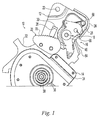
- FIGS. 1 to 6 show a parking brake mechanism 10 according to a preferred embodiment of the present invention.
- the illustrated parking brake mechanism 10 includes a mounting bracket 12, an actuator arm 14 pivotably secured to the mounting bracket 12 and movable between a brake-released position and a brake-applied position, and a lock 16 operable to releasably secure the actuator arm 14 in the brake-applied position and including a pawl 18 engagable with a ratchet 20.
- the illustrated mounting bracket 12 is sized and shaped to be secured to the motor vehicle to fix the parking brake mechanism 10 in a desired position.
- the illustrated mounting bracket 12 is provided with openings 22 for mounting fasteners but any other suitable securing means can alternatively be utilized.
- the illustrated mounting bracket 12 includes a flange 24 that forms a first or rest stop or abutment 26 and a tab 28 which forms a second or return stop or abutment 30.
- the first and second stops 26, 30 form limits of travel for the pawl 18 as described in more detail hereinafter. It is noted that in FIGS. 1 to 6, only a portion of the mounting bracket 12 is shown. It is also noted that the mounting bracket 12 can alternatively have any other suitable size and shape.
- the illustrated actuator arm 14 includes a bracket member 32 and an arm member 34 secured together for pivotal motion together relative to the mounting bracket 12 about a pivot pin 36 forming a laterally extending pivot axis 38.
- the arm member 34 is elongate having a rearward facing pedal at a lower end thereof for depression by the driver.
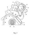
- the arm member 34 downwardly extends from the pivot axis 38 so that the driver can pressure the pedal to forwardly move the pedal and pivot the actuator arm 14 about the pivot axis 38 to generally move the top of the actuator arm 14 in the rearward direction about the pivot axis 38 (in the clockwise direction in FIGS. 1 to 6) from a brake-released position (shown in FIG. 1) to a brake-applied position (shown in figure 2).
- a parking brake cable connects vehicle parking brakes to the actuator arm 14 in a known manner so that the pivoting movement of the actuator arm 14 tensions and untensions the parking brake cable.
- the parking brake cable is untensioned when the actuator arm 14 is in the brake-release position and tensions the parking brake cable when in the brake-applied position.
- the actuator arm 14 can alternatively have any other suitable size and shape.
- the illustrated lock 16 includes the pawl 18 and the ratchet 20 which are sized, shaped and positioned to releasably secure the actuator arm 14 in the brake-applied position as described in more detail hereinafter. It is also noted that the lock 16 can alternatively have any other suitable form.
- the illustrated pawl and ratchet 18, 20 are also sized, shaped and positioned so that the lock 16 releases the actuator arm 14 when the driver pushes the pedal when the actuator arm 14 is locked in the brake-applied position by the lock 16. It is noted that the illustrated push to release feature can alternatively be replaced with any other suitable release such as a manually operated handle or a powered release.
- the illustrated pawl 18 includes an insert or inner portion 40 and a covering or outer portion 42 formed over the insert 40.
- the insert 40 is preferably formed a metal such as steel or the like.
- the outer portion 42 is preferably formed of a plastic. It is believed that Nytel 5526 is a suitable plastic but any other suitable plastic can alternatively be utilized. The plastic is preferably soft enough so that it deforms and/or dampens vibrations upon contact. However, the plastic is also preferably hard enough that it wears at an undesirable rate.
- the illustrated outer portion 42 is overmolded onto the insert 40 but can alternatively be formed and secured to the insert 40 in any other suitable manner such as, for example adhesive.
- the illustrated outer portion 42 covers the entire insert 40 except for tooling locations for holding and locating the insert 40 in the mold but it is noted that the outer portion 42 can alternatively cover less of the insert 40.
- the illustrated pawl 18 includes an opening 44 for receiving a pivot pin 46 and an opening 48 for cooperating with a spring member 50 as described in more detail hereinafter.
- the illustrated pawl 18 also includes a lock tooth 52 at a lower side thereof that is sized and shaped to cooperate with the ratchet 20 as described in more detail hereinafter.
- the illustrated pawl 18 includes a first resilient contact or engagement surface 54 that is sized and shaped to cooperate with the rest stop 26 of the mounting bracket 12 to limit rearward movement of the pawl 18 as described in more detail hereinafter.
- the illustrated pawl 18 includes a second resilient contact or engagement surface 56 that is sized and shaped to cooperate with the return stop 30 of the mounting bracket 12 to limit forward movement of the pawl 18 as described in more detail hereinafter.
- the illustrated pawl 18 includes third, fourth and fifth resilient contact or engagement surfaces 58, 60, 62 that are sized and shaped to cooperate with a reload cam or surface cam 64 of the actuator arm 14 to return the pawl 18 to its rest position as described in more detail hereinafter.
- the resilient engagement surfaces 54, 56, 58, 60, 62 are adapted to resiliently deform and or dampen vibrations upon impact of the pawl 18 with the other components and eliminate or substantially reduce noise that typically results from such impacts. It is noted that the illustrated plastic outer portion 42 of the pawl 18 eliminates metal to metal contact between the pawl 18 and the other components to further reduce the noise.
- the pawl 18 can have a greater or lesser number of the resilient engagement surfaces 54, 56, 58, 60, 62 depending on the number of contacts and noise requirements of the particular design.
- the illustrated resilient engagement surfaces 54, 56, 58, 60, 62 are spring members in the form of integral leaf springs.
- the integral leaf springs are formed by providing openings 66 in the outer portion of the pawl 18 located near the edge of the pawl 18 at the engagement surfaces 54, 56, 58, 60, 62.
- integral is used in this specification and the claims to mean a unitary or one piece component, that is, the illustrated leaf springs are part of a unitary one piece outer portion 42 of the pawl 18.
- the illustrated leaf springs are generally arc-shaped or curved to provide increased resiliency but any other suitable shape can alternatively be utilized. It is noted that the resilient engagement surfaces 54, 56, 58, 60, 62 can alternatively be formed in any other suitable manner. It is also noted that the pawl 18 can alternatively have any other suitable size and shape and can have any other number of the engagement surfaces 54, 56, 58, 60,62.
- the illustrated pawl 18 is pivotably secured to the mounting bracket 12 above the actuator arm 14 by the pivot pin 46 that forms a laterally extending pivot axis 68.
- the pawl 18 is located between the rest stop 26 and the return stop 30 to limit pivoting motion therebetween.
- the pawl 18 is resiliently biased by the spring member 50 toward its rest position wherein the first resilient engagement surface 54 is engaging the rest stop 26 of the mounting bracket 12.
- the illustrated spring member 50 is a torsion spring but it is noted that the spring member 50 can alternatively be any other suitable type of spring member.
- the illustrated ratchet 20 is secured to the actuator arm 14 for movement therewith as the actuator arm 14 pivots about its pivot axis 38 and includes a row of teeth 70.
- the teeth 70 are sized and shaped to cooperate with the pawl lock tooth 52 to permit movement of the ratchet 20 in the rearward direction when the pawl lock tooth 52 is engaging the ratchet teeth 70 but to prevent forward movement of the ratchet 20 in the forward direction when the pawl lock tooth 52 is engaging the ratchet teeth 70.
- the ratchet 20 can alternatively have any other suitable size and shape.
- the pawl's first resilient engagement surface 54 engages the rest stop 26 and the pawl's lock tooth 52 is disengaged from the ratchet teeth 70.
- the spring member 50 resiliently biases the pawl 18 into its rest position in engagement with the rest stop 26.
- the actuator arm 14 is in its rest or full rearward position so that the parking brake cable is untensioned and the parking brakes are disengaged from the vehicle wheels to permit rotation of the wheels.
- the upper end of the actuator arm 14 moves rearward and pivots the pawl 18 until the pawl's second resilient engagement surface 56 engages the return stop 30 to stop forward pivoting movement of the pawl 18.
- the contact between the second engagement surface 56 and the return stop 30 is substantially noise free or silent as the spring member dampens vibrations.
- a return spring moves the actuator arm 14 back toward its rest position (shown in FIG. 1).
- its reload surface or cam 64 sequentially engages the third, fourth and fifth resilient engagement surfaces 58, 60, 62 to pivot the pawl back to its rest position (shown in FIG. 1).
- the impact and contact between the third, fourth and fifth resilient engagement surfaces 58, 60, 62 and the return cam 64 is substantially noise free or silent as the spring members dampen vibrations.
- the pawl's first resilient engagement surface 54 engages the rest stop 26 when the pawl 18 reaches its rest position.
- the impact between the first engagement surface 54 and the rest stop 26 is substantially noise free or silent as the spring member dampens vibrations.
- the actuator arm 14 disengages the pawl 18 and continues to rotate toward its rest position.
- the parking brake mechanism 10 is in its rest position as described hereinabove with the parking brake cable untensioned and the parking brakes released from the vehicle wheels so that the vehicle wheels are free to rotate. Whenever desired, the driver can again apply the parking brakes with the parking brake mechanism 10 as described hereinabove.
- the pawl 18 of the parking brake mechanism 10 reduces and/or eliminates noise typically caused by a plurality of contacts between the pawl 18 and the mounting bracket 12, actuator arm 14, and/or the ratchet 20 because metal-to-metal contact has been eliminated and the resilient engagement surfaces 54, 56, 58, 60, 62 dampen vibrations. It is also apparent that the parking brake mechanism 10 according to the present invention is relatively easy to manufacture and assemble.
Landscapes
- Engineering & Computer Science (AREA)
- Transportation (AREA)
- Mechanical Engineering (AREA)
- Braking Elements And Transmission Devices (AREA)
- Braking Arrangements (AREA)
Abstract
Description
- The present invention generally relates to parking brake mechanisms and, more particularly, to parking brake mechanisms having a pawl-and-ratchet lock.
- Parking or emergency brake mechanisms for actuating cable operated brake mechanisms are well known and commercially used in motor vehicles. See, for example,
U.S. Patent Numbers 5,448,928 ,5,546,828 , and5,588,335 , the disclosures of which are expressly incorporated herein in their entireties by reference. Vehicle parking brake mechanisms are typically actuated by a foot-operated or hand-operated actuator lever positioned near the driver. The actuator lever is typically fixed to the vehicle by a mounting bracket or the like and attached to a brake cable connected to a vehicle parking brake system. The actuator lever is typically pivotably mounted on the mounting bracket and movable between a "brake released position" and one or more "brake applied positions." The brake cable is attached to the actuator lever so that rotation of the lever toward the "brake-applied positions" increases tension in the brake cable, thereby applying the parking brakes to the vehicle wheels to impede rotation thereof. A position lock is provided to releasably lock the actuator lever in a "brake-applied" position and a release mechanism is provided to selectively permit rotation of the lever back to the "brake released" position thereby decreasing tension in the brake cable and releasing the parking brakes from the wheels to permit rotation thereof. - Many parking brake mechanisms have a ratchet and pawl arrangement as part of the position or other lock. One disadvantage of this ratchet and pawl arrangement can be noise which is undesirable in some applications. These pawls engage many stops and the like and are also moved across teeth of the ratchets. All of these engagements can create "clicking" sounds.
- Parking brake mechanisms that attempt to eliminate and/or reduce this noise have been introduced, See, for example,
U.S. Patent Numbers 5,138,899 and6,843,150 , the disclosures of which are expressly incorporated herein in their entireties by reference. However, these "quiet-apply" parking brake mechanisms tend to be relatively complex and thus expensive to make and assemble. Additionally, there is a never ending desire to reduce the complexity and cost of motor vehicle components. Accordingly, there is a need in the art for an improved parking brake mechanism having relatively quiet operation. - The present invention provides a parking brake mechanism for a motor vehicle which addresses one or more problems of the related art. According to the present invention, a parking brake mechanism for a motor vehicle comprises, in combination, a mounting bracket, an actuator arm pivotably secured to the mounting bracket and movable between a brake-released position and a brake-applied position, and a lock operable to releasably secure the actuator arm in the brake-applied position and including a pawl engagable with a ratchet. The pawl includes a metal insert at least partially encapsulated in plastic.
- From the foregoing disclosure and the following more detailed description of various preferred embodiments it will be apparent to those skilled in the art that the present invention provides a significant advance in the technology and art of parking brake mechanisms for motor vehicles. Particularly significant in this regard is the potential the invention affords for providing a high quality, reliable, low cost, and relatively quiet mechanism. Additional features and advantages of various preferred embodiments will be better understood in view of the detailed description provided below.
- These and further features of the present invention will be apparent with reference to the following description and drawings, wherein:
- FIG. 1 is a fragmented, elevational view of a parking brake mechanism according to a preferred embodiment of the present invention, wherein components are removed for clarity and the mechanism is in a rest or "brake- released" position;
- FIG. 2 is a fragmented, elevational view of the parking brake mechanism of FIG. 1, wherein the mechanism is moving from a the rest position toward a lock or "brake-applied" position;
- FIG. 3 is a fragmented, elevational view of the parking brake mechanism of FIGS. 1 and 2, wherein the mechanism is in a lock or "brake-applied" position;
- FIG. 4 is a fragmented, elevational view of the parking brake mechanism of FIGS. 1 to 3, wherein the mechanism is in a release or "lock release" position;
- FIG. 5 is a fragmented, elevational view of the parking brake mechanism of FIGS. 1 to 4, wherein the mechanism is in a first reload position while moving from the release position back toward the rest position;
- FIG. 6 is a fragmented, elevational view of the parking brake mechanism of FIGS. 1 to 5, wherein the mechanism is in a second reload position while moving from the release position back toward the rest position;
- FIG. 7 is a perspective view of a pawl of the parking brake mechanism of FIGS. 1 to 6; and
- FIG. 8 is a perspective view of an insert of the pawl of FIG. 7.
- It should be understood that the appended drawings are not necessarily to scale, presenting a somewhat simplified representation of various preferred features illustrative of the basic principles of the invention. The specific design features of a parking brake mechanism for a motor vehicle as disclosed herein, including, for example, specific dimensions, orientations, locations, and shapes will be determined in part by the particular intended application and use environment. Certain features of the illustrated embodiments have been enlarged or distorted relative to others to facilitate visualization and clear understanding. In particular, thin features may be thickened, for example, for clarity or illustration. All references to direction and position, unless otherwise indicated, refer to the orientation of the parking brake mechanism illustrated in the drawings. In general, up or upward refers to an upward direction within the plane of the paper in FIG. 1 and down or downward refers to a downward direction within the plane of the paper in FIG. 1. Also in general, fore or forward refers to a direction toward the front of the motor vehicle, that is, toward the left within the plane of the paper in FIG. 1 and aft or rearward refers to a direction toward the rear of the motor vehicle, that is, to the right within the plane of the paper in FIG. 1.
- It will be apparent to those skilled in the art, that is, to those who have knowledge or experience in this area of technology, that many uses and design variations are possible for the improved parking brake mechanisms disclosed herein. The following detailed discussion of various alternative and preferred embodiments will illustrate the general principles of the invention with reference to foot-operated, push-to-release parking brake mechanism. Other embodiments suitable for other applications, such as, for example hand-operated mechanisms and/or handle or power released mechanisms will be apparent to those skilled in the art given the benefit of this disclosure.
- Referring now to the drawings, FIGS. 1 to 6 show a
parking brake mechanism 10 according to a preferred embodiment of the present invention. The illustratedparking brake mechanism 10 includes amounting bracket 12, anactuator arm 14 pivotably secured to themounting bracket 12 and movable between a brake-released position and a brake-applied position, and alock 16 operable to releasably secure theactuator arm 14 in the brake-applied position and including apawl 18 engagable with aratchet 20. - The illustrated
mounting bracket 12 is sized and shaped to be secured to the motor vehicle to fix theparking brake mechanism 10 in a desired position. The illustratedmounting bracket 12 is provided withopenings 22 for mounting fasteners but any other suitable securing means can alternatively be utilized. The illustratedmounting bracket 12 includes aflange 24 that forms a first or rest stop orabutment 26 and atab 28 which forms a second or return stop orabutment 30. The first and second stops 26, 30 form limits of travel for thepawl 18 as described in more detail hereinafter. It is noted that in FIGS. 1 to 6, only a portion of themounting bracket 12 is shown. It is also noted that themounting bracket 12 can alternatively have any other suitable size and shape. - The illustrated
actuator arm 14 includes abracket member 32 and anarm member 34 secured together for pivotal motion together relative to themounting bracket 12 about apivot pin 36 forming a laterally extendingpivot axis 38. Thearm member 34 is elongate having a rearward facing pedal at a lower end thereof for depression by the driver. Thearm member 34 downwardly extends from thepivot axis 38 so that the driver can pressure the pedal to forwardly move the pedal and pivot theactuator arm 14 about thepivot axis 38 to generally move the top of theactuator arm 14 in the rearward direction about the pivot axis 38 (in the clockwise direction in FIGS. 1 to 6) from a brake-released position (shown in FIG. 1) to a brake-applied position (shown in figure 2). A parking brake cable connects vehicle parking brakes to theactuator arm 14 in a known manner so that the pivoting movement of theactuator arm 14 tensions and untensions the parking brake cable. Preferably, the parking brake cable is untensioned when theactuator arm 14 is in the brake-release position and tensions the parking brake cable when in the brake-applied position. It is noted that theactuator arm 14 can alternatively have any other suitable size and shape. - The illustrated
lock 16 includes thepawl 18 and theratchet 20 which are sized, shaped and positioned to releasably secure theactuator arm 14 in the brake-applied position as described in more detail hereinafter. It is also noted that thelock 16 can alternatively have any other suitable form. The illustrated pawl andratchet lock 16 releases theactuator arm 14 when the driver pushes the pedal when theactuator arm 14 is locked in the brake-applied position by thelock 16. It is noted that the illustrated push to release feature can alternatively be replaced with any other suitable release such as a manually operated handle or a powered release. - As best shown in FIGS. 7 and 8, the illustrated
pawl 18 includes an insert or inner portion 40 and a covering orouter portion 42 formed over the insert 40. The insert 40 is preferably formed a metal such as steel or the like. Theouter portion 42 is preferably formed of a plastic. It is believed that Nytel 5526 is a suitable plastic but any other suitable plastic can alternatively be utilized. The plastic is preferably soft enough so that it deforms and/or dampens vibrations upon contact. However, the plastic is also preferably hard enough that it wears at an undesirable rate. The illustratedouter portion 42 is overmolded onto the insert 40 but can alternatively be formed and secured to the insert 40 in any other suitable manner such as, for example adhesive. The illustratedouter portion 42 covers the entire insert 40 except for tooling locations for holding and locating the insert 40 in the mold but it is noted that theouter portion 42 can alternatively cover less of the insert 40. - The illustrated
pawl 18 includes anopening 44 for receiving a pivot pin 46 and anopening 48 for cooperating with aspring member 50 as described in more detail hereinafter. The illustratedpawl 18 also includes alock tooth 52 at a lower side thereof that is sized and shaped to cooperate with theratchet 20 as described in more detail hereinafter. The illustratedpawl 18 includes a first resilient contact orengagement surface 54 that is sized and shaped to cooperate with therest stop 26 of the mountingbracket 12 to limit rearward movement of thepawl 18 as described in more detail hereinafter. The illustratedpawl 18 includes a second resilient contact orengagement surface 56 that is sized and shaped to cooperate with the return stop 30 of the mountingbracket 12 to limit forward movement of thepawl 18 as described in more detail hereinafter. The illustratedpawl 18 includes third, fourth and fifth resilient contact or engagement surfaces 58, 60, 62 that are sized and shaped to cooperate with a reload cam orsurface cam 64 of theactuator arm 14 to return thepawl 18 to its rest position as described in more detail hereinafter. The resilient engagement surfaces 54, 56, 58, 60, 62 are adapted to resiliently deform and or dampen vibrations upon impact of thepawl 18 with the other components and eliminate or substantially reduce noise that typically results from such impacts. It is noted that the illustrated plasticouter portion 42 of thepawl 18 eliminates metal to metal contact between thepawl 18 and the other components to further reduce the noise. Thepawl 18 can have a greater or lesser number of the resilient engagement surfaces 54, 56, 58, 60, 62 depending on the number of contacts and noise requirements of the particular design. The illustrated resilient engagement surfaces 54, 56, 58, 60, 62 are spring members in the form of integral leaf springs. The integral leaf springs are formed by providingopenings 66 in the outer portion of thepawl 18 located near the edge of thepawl 18 at the engagement surfaces 54, 56, 58, 60, 62. The term "integral" is used in this specification and the claims to mean a unitary or one piece component, that is, the illustrated leaf springs are part of a unitary one pieceouter portion 42 of thepawl 18. The illustrated leaf springs are generally arc-shaped or curved to provide increased resiliency but any other suitable shape can alternatively be utilized. It is noted that the resilient engagement surfaces 54, 56, 58, 60, 62 can alternatively be formed in any other suitable manner. It is also noted that thepawl 18 can alternatively have any other suitable size and shape and can have any other number of the engagement surfaces 54, 56, 58, 60,62. - As best shown in FIGS. 1 to 6, the illustrated
pawl 18 is pivotably secured to the mountingbracket 12 above theactuator arm 14 by the pivot pin 46 that forms a laterally extendingpivot axis 68. Thepawl 18 is located between therest stop 26 and the return stop 30 to limit pivoting motion therebetween. Thepawl 18 is resiliently biased by thespring member 50 toward its rest position wherein the firstresilient engagement surface 54 is engaging therest stop 26 of the mountingbracket 12. The illustratedspring member 50 is a torsion spring but it is noted that thespring member 50 can alternatively be any other suitable type of spring member. - As best shown in FIGS. 1 to 6, the illustrated
ratchet 20 is secured to theactuator arm 14 for movement therewith as theactuator arm 14 pivots about itspivot axis 38 and includes a row ofteeth 70. Theteeth 70 are sized and shaped to cooperate with thepawl lock tooth 52 to permit movement of theratchet 20 in the rearward direction when thepawl lock tooth 52 is engaging theratchet teeth 70 but to prevent forward movement of theratchet 20 in the forward direction when thepawl lock tooth 52 is engaging theratchet teeth 70. It is also noted that theratchet 20 can alternatively have any other suitable size and shape. - As best shown in FIG. 1, when the
parking brake mechanism 10 is in a rest or brake-released position, the pawl's firstresilient engagement surface 54 engages therest stop 26 and the pawl'slock tooth 52 is disengaged from theratchet teeth 70. Thespring member 50 resiliently biases thepawl 18 into its rest position in engagement with therest stop 26. Theactuator arm 14 is in its rest or full rearward position so that the parking brake cable is untensioned and the parking brakes are disengaged from the vehicle wheels to permit rotation of the wheels. - As best shown in FIG. 2, when the driver depresses the pedal to pivot the lower end of the
actuator arm 14 forward, the upper end of theactuator arm 14 and theratchet 20 are moved rearward toward thepawl 18. As the driver further depresses the pedal, theratchet 20 engages the pawl'slock tooth 52. As best shown in FIG. 3, when the driver releases the pedal and theparking brake mechanism 10 is in its lock or brake applied position, the pawl'slock tooth 52 engages atooth 70 of theratchet 20 to secure theactuator am 14 in its lock position and prevent return of theactuator arm 14 toward its rest position (shown in FIG. 1). Theactuator arm 14 is in its lock position so that the parking brake cable is tensioned and the parking brakes are engaged with the vehicle wheels to inhibit rotation of the wheels. - As best shown in FIG. 4, when the driver further depresses the pedal to release the parking brakes, the upper end of the
actuator arm 14 moves rearward and pivots thepawl 18 until the pawl's secondresilient engagement surface 56 engages the return stop 30 to stop forward pivoting movement of thepawl 18. The contact between thesecond engagement surface 56 and thereturn stop 30 is substantially noise free or silent as the spring member dampens vibrations. Once thepawl 18 stops, further movement of theactuator arm 14 disengages theratchet teeth 70 from the pawl'slock tooth 52. - As best shown in FIGS. 5 and 6, once the driver releases the pedal, a return spring moves the
actuator arm 14 back toward its rest position (shown in FIG. 1). As the upper end of theactuator arm 14 moves in the forward direction, its reload surface orcam 64 sequentially engages the third, fourth and fifth resilient engagement surfaces 58, 60, 62 to pivot the pawl back to its rest position (shown in FIG. 1). The impact and contact between the third, fourth and fifth resilient engagement surfaces 58, 60, 62 and thereturn cam 64 is substantially noise free or silent as the spring members dampen vibrations. As best shown in FIG 1, the pawl's firstresilient engagement surface 54 engages therest stop 26 when thepawl 18 reaches its rest position. The impact between thefirst engagement surface 54 and therest stop 26 is substantially noise free or silent as the spring member dampens vibrations. Once thepawl 18 is in its rest position, theactuator arm 14 disengages thepawl 18 and continues to rotate toward its rest position. Once theactuator arm 14 is in its rest position, theparking brake mechanism 10 is in its rest position as described hereinabove with the parking brake cable untensioned and the parking brakes released from the vehicle wheels so that the vehicle wheels are free to rotate. Whenever desired, the driver can again apply the parking brakes with theparking brake mechanism 10 as described hereinabove. - It is apparent from the above detailed description, that the
pawl 18 of theparking brake mechanism 10 according to the present invention reduces and/or eliminates noise typically caused by a plurality of contacts between thepawl 18 and the mountingbracket 12,actuator arm 14, and/or theratchet 20 because metal-to-metal contact has been eliminated and the resilient engagement surfaces 54, 56, 58, 60, 62 dampen vibrations. It is also apparent that theparking brake mechanism 10 according to the present invention is relatively easy to manufacture and assemble. - From the foregoing disclosure and detailed description of certain preferred embodiments, it is also apparent that various modifications, additions and other alternative embodiments are possible without departing from the true scope and spirit of the present invention. The embodiments discussed were chosen and described to provide the best illustration of the principles of the present invention and its practical application to thereby enable one of ordinary skill in the art to utilize the invention in various embodiments and with various modifications as are suited to the particular use contemplated. All such modifications and variations are within the scope of the present invention as determined by the appended claims when interpreted in accordance with the benefit to which they are fairly, legally, and equitably entitled.
Claims (10)
- A parking brake mechanism for a motor vehicle comprising, in combination:a mounting bracket;an actuator arm pivotably secured to the mounting bracket and movable between a brake-released position and a brake-applied position;a lock operable to releasably secure the actuator arm in the brake-applied position and including a pawl engagable with a ratchet; andwherein the pawl includes a metal insert at least partially encapsulated in plastic.
- The parking brake mechanism according to claim 1, wherein the plastic provides at least one resilient engagement surface.
- The parking brake mechanism according to claim 1 or 2, wherein the plastic forms at least one leaf spring.
- The parking brake mechanism according to any preceding claim, wherein the plastic forms a plurality of leaf springs.
- The parking brake mechanism according to any preceding claim, wherein the plastic forms at least one a resilient spring member that reduces noise upon contact.
- The parking brake mechanism according to claim 5, wherein the plastic forms a plurality of the spring members.
- The parking brake mechanism according to any preceding claim, wherein the pawl includes a lock tooth that engages the ratchet and at least an engagement portion of the tooth is covered by the plastic.
- The parking brake mechanism according to any preceding claim, wherein the mounting bracket includes first and second stops and the pawl is pivotable relative to the mounting bracket between the first and second stops and engagement surfaces of the pawl which engage the first and second stops are formed by the plastic.
- The parking brake mechanism according to any preceding claim, wherein the actuator arm includes a reload surface to move the pawl as the actuator arm moves toward the brake-released position and engagement surfaces of the pawl which engage the reload surface are formed by the plastic.
- The parking brake mechanism according to any preceding claim, wherein the plastic dampens vibrations upon contact.
Applications Claiming Priority (2)
| Application Number | Priority Date | Filing Date | Title |
|---|---|---|---|
| US70803805P | 2005-08-12 | 2005-08-12 | |
| US11/463,168 US20070068317A1 (en) | 2005-08-12 | 2006-08-08 | Ratchet-type parking brake having quiet operation |
Publications (3)
| Publication Number | Publication Date |
|---|---|
| EP1752347A2 true EP1752347A2 (en) | 2007-02-14 |
| EP1752347A3 EP1752347A3 (en) | 2008-03-19 |
| EP1752347B1 EP1752347B1 (en) | 2009-11-18 |
Family
ID=37440747
Family Applications (1)
| Application Number | Title | Priority Date | Filing Date |
|---|---|---|---|
| EP06016804A Not-in-force EP1752347B1 (en) | 2005-08-12 | 2006-08-11 | Ratchet type parking brake having quiet operation |
Country Status (5)
| Country | Link |
|---|---|
| US (1) | US20070068317A1 (en) |
| EP (1) | EP1752347B1 (en) |
| JP (1) | JP2007050884A (en) |
| AT (1) | ATE448982T1 (en) |
| DE (1) | DE602006010485D1 (en) |
Cited By (3)
| Publication number | Priority date | Publication date | Assignee | Title |
|---|---|---|---|---|
| EP2006176A2 (en) | 2007-06-20 | 2008-12-24 | DGS Druckguss Systeme AG | Fixing brake device |
| WO2009071059A1 (en) * | 2007-12-05 | 2009-06-11 | Edscha Ag | Motor vehicle parking brake |
| EP2810833A4 (en) * | 2012-02-01 | 2016-07-13 | Toyota Tekko Kk | Parking brake device |
Families Citing this family (7)
| Publication number | Priority date | Publication date | Assignee | Title |
|---|---|---|---|---|
| AU2010308068A1 (en) * | 2009-10-12 | 2012-05-03 | Waytag (Proprietary) Limited | A locating system and a method for operating a locating system |
| DE102011018507A1 (en) * | 2011-04-23 | 2012-10-25 | Power-Cast Light Metal Solutions Gmbh & Co. Kg | Operating device for parking brake of motor car, has spring element provided as component of retainer for pressing lock pawl against locking segment of fixing device, where segment of pawl is mounted in retainer in play-free manner |
| JP6027045B2 (en) * | 2014-04-02 | 2016-11-16 | 豊田鉄工株式会社 | Parking brake device |
| DE102014207823B4 (en) | 2014-04-25 | 2021-12-09 | Volkswagen Aktiengesellschaft | Pawl for a vehicle handbrake |
| US9845083B2 (en) * | 2015-07-01 | 2017-12-19 | Dura Operating, Llc | Park brake control assembly |
| US11072392B2 (en) * | 2018-11-08 | 2021-07-27 | Shimano Inc. | Bicycle operating device |
| KR102548635B1 (en) * | 2020-07-17 | 2023-06-28 | 동원산업 주식회사 | Noise reduction device for vehicle parking brake |
Citations (6)
| Publication number | Priority date | Publication date | Assignee | Title |
|---|---|---|---|---|
| US4519270A (en) * | 1981-11-16 | 1985-05-28 | Toyota Jidosha Kabushiki Kaisha | Foot-operated control device for parking brake |
| US4872368A (en) * | 1988-07-28 | 1989-10-10 | Orscheln Co. | Push-to-release cable operating apparatus |
| DE29800573U1 (en) * | 1998-01-15 | 1998-02-26 | Porsche Ag | Actuator |
| US6286389B1 (en) * | 1999-01-21 | 2001-09-11 | Ventra Group Inc. | Parking brake actuating assembly with improved lockout structure |
| JP2002302024A (en) * | 2001-04-03 | 2002-10-15 | Masuda Seisakusho:Kk | Foot parking brake device |
| WO2004087476A2 (en) * | 2003-04-03 | 2004-10-14 | Fico Cables S.A. | Parking brake lever unit |
Family Cites Families (7)
| Publication number | Priority date | Publication date | Assignee | Title |
|---|---|---|---|---|
| JPS5397151A (en) * | 1977-02-02 | 1978-08-25 | Kanji Imazaike | Gear |
| US5328219A (en) * | 1992-12-24 | 1994-07-12 | General Motors Corporation | Vehicle closure latch |
| JP2000177546A (en) * | 1998-12-17 | 2000-06-27 | Otsuka Koki Co Ltd | Foot parking brake device |
| GB0006932D0 (en) * | 2000-03-23 | 2000-05-10 | Meritor Light Vehicle Sys Ltd | Latch mechanism |
| GB0319030D0 (en) * | 2003-08-13 | 2003-09-17 | Arvinmeritor Light Vehicle Sys | Latch mechanism |
| JP4590230B2 (en) * | 2004-08-24 | 2010-12-01 | 本田技研工業株式会社 | Stepping parking brake device |
| JP4844063B2 (en) * | 2004-10-13 | 2011-12-21 | 株式会社アドヴィックス | Foot-operated parking brake device for vehicles |
-
2006
- 2006-08-08 US US11/463,168 patent/US20070068317A1/en not_active Abandoned
- 2006-08-11 AT AT06016804T patent/ATE448982T1/en not_active IP Right Cessation
- 2006-08-11 EP EP06016804A patent/EP1752347B1/en not_active Not-in-force
- 2006-08-11 DE DE602006010485T patent/DE602006010485D1/en active Active
- 2006-08-11 JP JP2006219088A patent/JP2007050884A/en active Pending
Patent Citations (6)
| Publication number | Priority date | Publication date | Assignee | Title |
|---|---|---|---|---|
| US4519270A (en) * | 1981-11-16 | 1985-05-28 | Toyota Jidosha Kabushiki Kaisha | Foot-operated control device for parking brake |
| US4872368A (en) * | 1988-07-28 | 1989-10-10 | Orscheln Co. | Push-to-release cable operating apparatus |
| DE29800573U1 (en) * | 1998-01-15 | 1998-02-26 | Porsche Ag | Actuator |
| US6286389B1 (en) * | 1999-01-21 | 2001-09-11 | Ventra Group Inc. | Parking brake actuating assembly with improved lockout structure |
| JP2002302024A (en) * | 2001-04-03 | 2002-10-15 | Masuda Seisakusho:Kk | Foot parking brake device |
| WO2004087476A2 (en) * | 2003-04-03 | 2004-10-14 | Fico Cables S.A. | Parking brake lever unit |
Cited By (4)
| Publication number | Priority date | Publication date | Assignee | Title |
|---|---|---|---|---|
| EP2006176A2 (en) | 2007-06-20 | 2008-12-24 | DGS Druckguss Systeme AG | Fixing brake device |
| WO2009071059A1 (en) * | 2007-12-05 | 2009-06-11 | Edscha Ag | Motor vehicle parking brake |
| US8839691B2 (en) | 2007-12-05 | 2014-09-23 | Edscha Engineering Gmbh | Motor vehicle parking brake |
| EP2810833A4 (en) * | 2012-02-01 | 2016-07-13 | Toyota Tekko Kk | Parking brake device |
Also Published As
| Publication number | Publication date |
|---|---|
| ATE448982T1 (en) | 2009-12-15 |
| EP1752347A3 (en) | 2008-03-19 |
| EP1752347B1 (en) | 2009-11-18 |
| DE602006010485D1 (en) | 2009-12-31 |
| US20070068317A1 (en) | 2007-03-29 |
| JP2007050884A (en) | 2007-03-01 |
Similar Documents
| Publication | Publication Date | Title |
|---|---|---|
| EP1752347A2 (en) | Ratchet type parking brake having quiet operation | |
| US7472624B2 (en) | Push to release brake actuating assembly for a vehicle | |
| EP0527518B1 (en) | Self-adjusting, push to-release parking brake | |
| US9278671B2 (en) | Parking brake device | |
| US4864886A (en) | Console integrated pull to release parking brake actuator | |
| EP1728698A1 (en) | Parking brake actuator with clutch spring assembly | |
| US20070227290A1 (en) | Pull-to-release hand brake | |
| US5816111A (en) | Actuator for a hand brake of a motor vehicle | |
| US20070227288A1 (en) | Push-to-release foot brake with eccentric torsion-lock self adjust mechanism | |
| US5054333A (en) | Movable pedal lever stop | |
| JP4393255B2 (en) | Pedal parking brake operation device | |
| US20030019317A1 (en) | Parking brake system having multi-tooth, self-engaging self-adjust pawl | |
| US7650815B2 (en) | Brake actuator with retainer for restricting lateral movement of lever | |
| US6880426B2 (en) | Parking brake for a motor vehicle | |
| US20050211009A1 (en) | Safety release feature | |
| US8096389B2 (en) | Cable connector for use in a brake actuating system | |
| JP4234033B2 (en) | Automobile operation pedal device | |
| US4403524A (en) | Headlamp door lever assembly | |
| US20020174737A1 (en) | Parking brake actuator with anti-release feature | |
| JP6765112B2 (en) | Foot-operated parking brake device | |
| US7478575B2 (en) | Brake actuating assembly for a vehicle | |
| US20080115617A1 (en) | Parking Brake for a Vehicle | |
| CA2488604C (en) | Quiet apply push to release parking brake pedal | |
| GB2184524A (en) | Locking motor-vehicle parking brake | |
| US20070234840A1 (en) | Push-to-release foot brake with eccentric pawl-and-sector self adjust mechanism |
Legal Events
| Date | Code | Title | Description |
|---|---|---|---|
| PUAI | Public reference made under article 153(3) epc to a published international application that has entered the european phase |
Free format text: ORIGINAL CODE: 0009012 |
|
| AK | Designated contracting states |
Kind code of ref document: A2 Designated state(s): AT BE BG CH CY CZ DE DK EE ES FI FR GB GR HU IE IS IT LI LT LU LV MC NL PL PT RO SE SI SK TR |
|
| AX | Request for extension of the european patent |
Extension state: AL BA HR MK YU |
|
| PUAL | Search report despatched |
Free format text: ORIGINAL CODE: 0009013 |
|
| AK | Designated contracting states |
Kind code of ref document: A3 Designated state(s): AT BE BG CH CY CZ DE DK EE ES FI FR GB GR HU IE IS IT LI LT LU LV MC NL PL PT RO SE SI SK TR |
|
| AX | Request for extension of the european patent |
Extension state: AL BA HR MK YU |
|
| 17P | Request for examination filed |
Effective date: 20080926 |
|
| AKX | Designation fees paid |
Designated state(s): AT BE BG CH CY CZ DE DK EE ES FI FR GB GR HU IE IS IT LI LT LU LV MC NL PL PT RO SE SI SK TR |
|
| 17Q | First examination report despatched |
Effective date: 20081030 |
|
| GRAP | Despatch of communication of intention to grant a patent |
Free format text: ORIGINAL CODE: EPIDOSNIGR1 |
|
| GRAS | Grant fee paid |
Free format text: ORIGINAL CODE: EPIDOSNIGR3 |
|
| GRAA | (expected) grant |
Free format text: ORIGINAL CODE: 0009210 |
|
| AK | Designated contracting states |
Kind code of ref document: B1 Designated state(s): AT BE BG CH CY CZ DE DK EE ES FI FR GB GR HU IE IS IT LI LT LU LV MC NL PL PT RO SE SI SK TR |
|
| REG | Reference to a national code |
Ref country code: GB Ref legal event code: FG4D |
|
| REG | Reference to a national code |
Ref country code: CH Ref legal event code: EP |
|
| REG | Reference to a national code |
Ref country code: IE Ref legal event code: FG4D |
|
| REF | Corresponds to: |
Ref document number: 602006010485 Country of ref document: DE Date of ref document: 20091231 Kind code of ref document: P |
|
| REG | Reference to a national code |
Ref country code: NL Ref legal event code: VDEP Effective date: 20091118 |
|
| LTIE | Lt: invalidation of european patent or patent extension |
Effective date: 20091118 |
|
| PG25 | Lapsed in a contracting state [announced via postgrant information from national office to epo] |
Ref country code: FI Free format text: LAPSE BECAUSE OF FAILURE TO SUBMIT A TRANSLATION OF THE DESCRIPTION OR TO PAY THE FEE WITHIN THE PRESCRIBED TIME-LIMIT Effective date: 20091118 Ref country code: LT Free format text: LAPSE BECAUSE OF FAILURE TO SUBMIT A TRANSLATION OF THE DESCRIPTION OR TO PAY THE FEE WITHIN THE PRESCRIBED TIME-LIMIT Effective date: 20091118 Ref country code: SE Free format text: LAPSE BECAUSE OF FAILURE TO SUBMIT A TRANSLATION OF THE DESCRIPTION OR TO PAY THE FEE WITHIN THE PRESCRIBED TIME-LIMIT Effective date: 20091118 Ref country code: PT Free format text: LAPSE BECAUSE OF FAILURE TO SUBMIT A TRANSLATION OF THE DESCRIPTION OR TO PAY THE FEE WITHIN THE PRESCRIBED TIME-LIMIT Effective date: 20100318 Ref country code: ES Free format text: LAPSE BECAUSE OF FAILURE TO SUBMIT A TRANSLATION OF THE DESCRIPTION OR TO PAY THE FEE WITHIN THE PRESCRIBED TIME-LIMIT Effective date: 20100228 Ref country code: IS Free format text: LAPSE BECAUSE OF FAILURE TO SUBMIT A TRANSLATION OF THE DESCRIPTION OR TO PAY THE FEE WITHIN THE PRESCRIBED TIME-LIMIT Effective date: 20100318 |
|
| PG25 | Lapsed in a contracting state [announced via postgrant information from national office to epo] |
Ref country code: PL Free format text: LAPSE BECAUSE OF FAILURE TO SUBMIT A TRANSLATION OF THE DESCRIPTION OR TO PAY THE FEE WITHIN THE PRESCRIBED TIME-LIMIT Effective date: 20091118 Ref country code: CY Free format text: LAPSE BECAUSE OF FAILURE TO SUBMIT A TRANSLATION OF THE DESCRIPTION OR TO PAY THE FEE WITHIN THE PRESCRIBED TIME-LIMIT Effective date: 20091118 Ref country code: LV Free format text: LAPSE BECAUSE OF FAILURE TO SUBMIT A TRANSLATION OF THE DESCRIPTION OR TO PAY THE FEE WITHIN THE PRESCRIBED TIME-LIMIT Effective date: 20091118 Ref country code: SI Free format text: LAPSE BECAUSE OF FAILURE TO SUBMIT A TRANSLATION OF THE DESCRIPTION OR TO PAY THE FEE WITHIN THE PRESCRIBED TIME-LIMIT Effective date: 20091118 |
|
| PG25 | Lapsed in a contracting state [announced via postgrant information from national office to epo] |
Ref country code: AT Free format text: LAPSE BECAUSE OF FAILURE TO SUBMIT A TRANSLATION OF THE DESCRIPTION OR TO PAY THE FEE WITHIN THE PRESCRIBED TIME-LIMIT Effective date: 20091118 Ref country code: BE Free format text: LAPSE BECAUSE OF FAILURE TO SUBMIT A TRANSLATION OF THE DESCRIPTION OR TO PAY THE FEE WITHIN THE PRESCRIBED TIME-LIMIT Effective date: 20091118 |
|
| PG25 | Lapsed in a contracting state [announced via postgrant information from national office to epo] |
Ref country code: EE Free format text: LAPSE BECAUSE OF FAILURE TO SUBMIT A TRANSLATION OF THE DESCRIPTION OR TO PAY THE FEE WITHIN THE PRESCRIBED TIME-LIMIT Effective date: 20091118 Ref country code: NL Free format text: LAPSE BECAUSE OF FAILURE TO SUBMIT A TRANSLATION OF THE DESCRIPTION OR TO PAY THE FEE WITHIN THE PRESCRIBED TIME-LIMIT Effective date: 20091118 Ref country code: BG Free format text: LAPSE BECAUSE OF FAILURE TO SUBMIT A TRANSLATION OF THE DESCRIPTION OR TO PAY THE FEE WITHIN THE PRESCRIBED TIME-LIMIT Effective date: 20100218 Ref country code: DK Free format text: LAPSE BECAUSE OF FAILURE TO SUBMIT A TRANSLATION OF THE DESCRIPTION OR TO PAY THE FEE WITHIN THE PRESCRIBED TIME-LIMIT Effective date: 20091118 Ref country code: RO Free format text: LAPSE BECAUSE OF FAILURE TO SUBMIT A TRANSLATION OF THE DESCRIPTION OR TO PAY THE FEE WITHIN THE PRESCRIBED TIME-LIMIT Effective date: 20091118 |
|
| PG25 | Lapsed in a contracting state [announced via postgrant information from national office to epo] |
Ref country code: SK Free format text: LAPSE BECAUSE OF FAILURE TO SUBMIT A TRANSLATION OF THE DESCRIPTION OR TO PAY THE FEE WITHIN THE PRESCRIBED TIME-LIMIT Effective date: 20091118 Ref country code: CZ Free format text: LAPSE BECAUSE OF FAILURE TO SUBMIT A TRANSLATION OF THE DESCRIPTION OR TO PAY THE FEE WITHIN THE PRESCRIBED TIME-LIMIT Effective date: 20091118 |
|
| PLBE | No opposition filed within time limit |
Free format text: ORIGINAL CODE: 0009261 |
|
| STAA | Information on the status of an ep patent application or granted ep patent |
Free format text: STATUS: NO OPPOSITION FILED WITHIN TIME LIMIT |
|
| 26N | No opposition filed |
Effective date: 20100819 |
|
| PG25 | Lapsed in a contracting state [announced via postgrant information from national office to epo] |
Ref country code: GR Free format text: LAPSE BECAUSE OF FAILURE TO SUBMIT A TRANSLATION OF THE DESCRIPTION OR TO PAY THE FEE WITHIN THE PRESCRIBED TIME-LIMIT Effective date: 20100219 |
|
| PG25 | Lapsed in a contracting state [announced via postgrant information from national office to epo] |
Ref country code: IT Free format text: LAPSE BECAUSE OF FAILURE TO SUBMIT A TRANSLATION OF THE DESCRIPTION OR TO PAY THE FEE WITHIN THE PRESCRIBED TIME-LIMIT Effective date: 20091118 Ref country code: MC Free format text: LAPSE BECAUSE OF NON-PAYMENT OF DUE FEES Effective date: 20100831 |
|
| REG | Reference to a national code |
Ref country code: CH Ref legal event code: PL |
|
| PG25 | Lapsed in a contracting state [announced via postgrant information from national office to epo] |
Ref country code: LI Free format text: LAPSE BECAUSE OF NON-PAYMENT OF DUE FEES Effective date: 20100831 Ref country code: CH Free format text: LAPSE BECAUSE OF NON-PAYMENT OF DUE FEES Effective date: 20100831 |
|
| PG25 | Lapsed in a contracting state [announced via postgrant information from national office to epo] |
Ref country code: IE Free format text: LAPSE BECAUSE OF NON-PAYMENT OF DUE FEES Effective date: 20100811 |
|
| PG25 | Lapsed in a contracting state [announced via postgrant information from national office to epo] |
Ref country code: HU Free format text: LAPSE BECAUSE OF FAILURE TO SUBMIT A TRANSLATION OF THE DESCRIPTION OR TO PAY THE FEE WITHIN THE PRESCRIBED TIME-LIMIT Effective date: 20100519 Ref country code: LU Free format text: LAPSE BECAUSE OF NON-PAYMENT OF DUE FEES Effective date: 20100811 |
|
| REG | Reference to a national code |
Ref country code: FR Ref legal event code: PLFP Year of fee payment: 11 |
|
| PGFP | Annual fee paid to national office [announced via postgrant information from national office to epo] |
Ref country code: TR Payment date: 20160726 Year of fee payment: 11 |
|
| REG | Reference to a national code |
Ref country code: FR Ref legal event code: PLFP Year of fee payment: 12 |
|
| REG | Reference to a national code |
Ref country code: FR Ref legal event code: PLFP Year of fee payment: 13 |
|
| PGFP | Annual fee paid to national office [announced via postgrant information from national office to epo] |
Ref country code: DE Payment date: 20180829 Year of fee payment: 13 Ref country code: FR Payment date: 20180827 Year of fee payment: 13 |
|
| PGFP | Annual fee paid to national office [announced via postgrant information from national office to epo] |
Ref country code: GB Payment date: 20180828 Year of fee payment: 13 |
|
| REG | Reference to a national code |
Ref country code: DE Ref legal event code: R119 Ref document number: 602006010485 Country of ref document: DE |
|
| GBPC | Gb: european patent ceased through non-payment of renewal fee |
Effective date: 20190811 |
|
| PG25 | Lapsed in a contracting state [announced via postgrant information from national office to epo] |
Ref country code: FR Free format text: LAPSE BECAUSE OF NON-PAYMENT OF DUE FEES Effective date: 20190831 Ref country code: DE Free format text: LAPSE BECAUSE OF NON-PAYMENT OF DUE FEES Effective date: 20200303 |
|
| PG25 | Lapsed in a contracting state [announced via postgrant information from national office to epo] |
Ref country code: GB Free format text: LAPSE BECAUSE OF NON-PAYMENT OF DUE FEES Effective date: 20190811 |
|
| PG25 | Lapsed in a contracting state [announced via postgrant information from national office to epo] |
Ref country code: TR Free format text: LAPSE BECAUSE OF NON-PAYMENT OF DUE FEES Effective date: 20170811 |