EP2006176A2 - Fixing brake device - Google Patents
Fixing brake device Download PDFInfo
- Publication number
- EP2006176A2 EP2006176A2 EP08158655A EP08158655A EP2006176A2 EP 2006176 A2 EP2006176 A2 EP 2006176A2 EP 08158655 A EP08158655 A EP 08158655A EP 08158655 A EP08158655 A EP 08158655A EP 2006176 A2 EP2006176 A2 EP 2006176A2
- Authority
- EP
- European Patent Office
- Prior art keywords
- pawl
- stop
- parking brake
- brake device
- brake lever
- Prior art date
- Legal status (The legal status is an assumption and is not a legal conclusion. Google has not performed a legal analysis and makes no representation as to the accuracy of the status listed.)
- Granted
Links
Images

Classifications
-
- B—PERFORMING OPERATIONS; TRANSPORTING
- B60—VEHICLES IN GENERAL
- B60T—VEHICLE BRAKE CONTROL SYSTEMS OR PARTS THEREOF; BRAKE CONTROL SYSTEMS OR PARTS THEREOF, IN GENERAL; ARRANGEMENT OF BRAKING ELEMENTS ON VEHICLES IN GENERAL; PORTABLE DEVICES FOR PREVENTING UNWANTED MOVEMENT OF VEHICLES; VEHICLE MODIFICATIONS TO FACILITATE COOLING OF BRAKES
- B60T7/00—Brake-action initiating means
- B60T7/02—Brake-action initiating means for personal initiation
- B60T7/08—Brake-action initiating means for personal initiation hand actuated
- B60T7/10—Disposition of hand control
- B60T7/102—Disposition of hand control by means of a tilting lever
- B60T7/104—Disposition of hand control by means of a tilting lever with a locking mechanism
Definitions
- the invention relates to a parking brake device with a locking device having a brake lever, which has a locking segment and engaging in this pawl which engages in interdental spaces of the locking segment, wherein the pawl is connected to a biasing member and with an unlocking device.
- a hand brake lever with a locking device which consists of a locking segment and a pawl is, for example, from DE 103 24 040 A1 known.
- both pawl and locking segment are made of metal, so that there is a considerable noise pollution during operation. This noise pollution can theoretically be prevented by making one of the components of a softer or elastic material, such as plastic. However, this has an impairment of the service life and a threat to operational safety result.
- Object of the present invention is to provide a structurally simple solution that allows a substantial minimization of the operating noise.
- the solution should be inexpensive to produce and satisfy all the requirements in terms of safety and longevity.
- the parking brake according to the invention have a particularly low weight and be produced in advanced lightweight construction method. Another requirement is to make the components as compact as possible.
- a stop for the pawl which dampens the impact of the pawl in the interdental spaces of the locking segment.
- the essential feature of the present invention is that upon actuation of the parking brake device, the pawl is not pressed after exceeding a tooth of the locking segment in the subsequent interdental space, but that previously a damping is effected by the stop.
- the biasing element exerts sufficient force, or a sufficient moment on the pawl to ensure a secure engagement in the locking segment.
- a particularly favored embodiment of the invention provides that the pawl is mounted on the brake lever and that the stop is firmly connected to the brake lever. In this way, a particularly simple and inexpensive solution can be achieved, which also has a low weight.
- the pawl and the stop are received in a recess of the brake lever.
- the brake lever is usually a plate-shaped component, which must have a certain thickness in order to have sufficient rigidity.
- the overall dimensions of the handbrake can now be substantially reduced by the fact that both the pawl and the stop are recessed. This naturally has the consequence that the locking segment protrudes into this recess.
- a further optimization of the compact design can be achieved that seen from the axis of the pawl of the pawl, the point at which the push rod attacks, and the stop surface are in an angular range which is smaller than 180 °.
- the pawl is designed substantially as a one-armed lever which is mounted at one end and at one lever arm all points of attack of the forces.
- the points of attack it is generally not feasible for the points of attack to be on a beam emanating from the axis, but it is sufficient for them to be on one side of the axis to achieve the set objectives of the compact design.
- a further particularly preferred embodiment of the invention provides that the pawl is formed substantially spherical and has a concave abutment surface which has a first portion which approaches tangentially to the stop and which further comprises a second portion which in the engaged state substantially abuts perpendicular to the stop.
- Another particularly advantageous embodiment of the invention provides that the stop cooperates with a stop surface on the pawl and that upon contact of the stop on the stop surface with little force, the pawl is removed from the interdental spaces and that the pawl while exerting the bias of the biasing member completely engages in the interdental spaces, wherein an elastic element of the stopper and / or the stop surface is deformed. It is essential that the pawl is braked by the stop only immediately before hitting the interdental space of the locking segment. In this way, an inadmissible reduction of the holding force can be avoided.
- the stop is designed as a plastic component which is received in a recess of the brake lever.
- the one-piece design a considerable simplification is achieved.
- stop is elastic.
- an elastic element is applied to the stop surface, wherein both solutions can be carried out together.
- the parking brake device 1 designed as a hand brake device has a hand brake lever 2 with a locking device 3 and an unlocking device 4.
- the existing example of light metal handbrake lever 2 is pivotally mounted in a bearing block 5 about an axis 6.
- the locking device 3 consists of a blocking segment 7 and a cooperating with the locking segment 4 pawl 8, which is formed substantially as a rotatable about an axis 16 component.
- the pawl 8 is rotatably supported in the hand brake lever 2 by means of a bearing pin 9.
- the pawl 8 has at the locking segment 7 facing the end of a pawl 10 which engages in ratchet teeth 11 of the locking segment 7.
- the pawl 8 can be unlocked via the locking segment 7 acting on the unlocking device 4, wherein the unlocking device 4 in the present example a loaded by a spring, not shown, in the brake lever 2 slidably mounted push rod 13 which is actuated by a push button 4.
- the stop 12 is formed as a mushroom-shaped plastic component which is received positively in a recess of the handbrake lever 2. It is essential that the material be sufficiently elastic to allow a deformation of about 1 mm. Well suited in this context, for example polyurethane, rubber or other sufficiently flexible plastic.
- the pawl 8 may be biased by a directly acting on this torsion spring in the engagement direction, which is shown by arrow 18.
- both the pawl 8 and the stop 12 are arranged in a recess 22 of the brake lever 2. This means that the said components 8, 12 are completely received in the illustrated embodiment between the side surfaces 23, 24 of the plate-shaped lever 2. Furthermore, it is off Fig. 2 it can be seen that accordingly the blocking segment 7 is located in the interior of this recess 22 and projects into the recess.
- the pawl 8 has a stop surface 15 which has a first portion 25 and a second portion 27 which are interconnected by a concave portion 26.
- the stop surface 15 approximately approaches the stop 12 approximately tangentially in the region of the first section 25 when rotating about the axis 16, and the first contact takes place gently in the form of a sliding contact.
- the contact point moves along the concave portion 26 to the second portion 27, in which the contact then takes place substantially perpendicular to the local direction of movement, so that apart from the deformation of the stop 12 is given a defined stop point.
- a gentle engagement of the pawl 8 is ensured even when using less compliant material on the stop 12.
- it is off Fig. 5 It can be seen that the entire stop surface 15, the point 17 of the force F and the pawl 10 are in an angular range 28, which makes up 135 ° in the illustrated embodiment and should in any case be less than 180 °.
- the force F is shown as a function of the distance s traveled by the pawl 10 during rotation about the axis 16 of the pawl 8.
- the assumption is made that the pawl 10 is located exactly above the tooth space 14.
- the pawl 8 is free to move and there is no contact with the locking segment 7 still with the stop 12 instead.
- this is slightly on the stop 12 at.
- the stop is increasingly deformed and the attacking force in point 17 increases continuously along the line 20 to a value F 1 .
Landscapes
- Engineering & Computer Science (AREA)
- Transportation (AREA)
- Mechanical Engineering (AREA)
- Braking Elements And Transmission Devices (AREA)
- Braking Arrangements (AREA)
Abstract
Description
Die Erfindung betrifft eine Feststellbremseinrichtung mit einem eine Arretiervorrichtung aufweisenden Bremshebel, welche ein Sperrsegment und eine in dieses eingreifende Sperrklinke aufweist, die in Zahnzwischenräume des Sperrsegments eingreift, wobei die Sperrklinke mit einem Vorspannelement und mit einer Entriegelungseinrichtung verbunden ist.The invention relates to a parking brake device with a locking device having a brake lever, which has a locking segment and engaging in this pawl which engages in interdental spaces of the locking segment, wherein the pawl is connected to a biasing member and with an unlocking device.
Ein Handbremshebel mit einer Arretiereinrichtung, welche aus einem Sperrsegment und einer Sperrklinke besteht, ist beispielsweise aus der
Beim Betätigen einer Feststellbremse rastet die Sperrklinke nacheinander in jeden Zahnzwischenraum des Sperrsegments ein, um die erforderliche Arretierung zu gewährleisten. In der Regel werden sowohl Sperrklinke als auch Sperrsegment aus Metall hergestellt, so dass sich bei der Betätigung eine erhebliche Geräuschbelastung ergibt. Diese Geräuschbelastung kann theoretisch dadurch verhindert werden, dass einer der Bauteile aus einem weicheren bzw. elastischen Material, wie etwa aus Kunststoff, hergestellt wird. Dies hat jedoch eine Beeinträchtigung der Lebensdauer und eine Gefährdung der Betriebssicherheit zur Folge.Upon actuation of a parking brake, the pawl engages successively in each interdental space of the locking segment to ensure the required locking. In general, both pawl and locking segment are made of metal, so that there is a considerable noise pollution during operation. This noise pollution can theoretically be prevented by making one of the components of a softer or elastic material, such as plastic. However, this has an impairment of the service life and a threat to operational safety result.
Aus der
Aufgabe der vorliegenden Erfindung ist es, eine konstruktiv einfache Lösung anzugeben, die eine weitgehende Minimierung des Betätigungsgeräusches ermöglicht. Die Lösung soll dabei kostengünstig herstellbar sein und sämtlichen Anforderungen hinsichtlich Sicherheit und Langlebigkeit genügen. Insbesondere soll die erfindungsgemäße Feststellbremse ein besonders geringes Gewicht aufweisen und in fortgeschrittenem Leichtbauverfahren herstellbar sein. Eine weitere Anforderung ist es, die Bauteile möglichst kompakt auszuführen.Object of the present invention is to provide a structurally simple solution that allows a substantial minimization of the operating noise. The solution should be inexpensive to produce and satisfy all the requirements in terms of safety and longevity. In particular, should the parking brake according to the invention have a particularly low weight and be produced in advanced lightweight construction method. Another requirement is to make the components as compact as possible.
Erfindungsgemäß werden diese Aufgaben dadurch gelöst, dass ein Anschlag für die Sperrklinke vorgesehen ist, der den Aufschlag der Sperrklinke in den Zahnzwischenräumen des Sperrsegments dämpft. Wesentlich an der vorliegenden Erfindung ist, dass bei der Betätigung der Feststellbremseinrichtung die Sperrklinke nach dem Überschreiten eines Zahnes des Sperrsegmentes nicht umgebremst in den nachfolgenden Zahnzwischenraum gedrückt wird, sondern dass zuvor eine Dämpfung durch den Anschlag bewirkt wird. Wie bereits oben ausgeführt, ist es für eine sichere Funktion einer Feststellbremseinrichtung erforderlich, dass das Vorspannelement eine ausreichende Kraft, bzw. ein ausreichendes Moment auf die Sperrklinke ausübt, um einen sicheren Eingriff in das Sperrsegment zu gewährleisten. Diese Kraft, bzw. dieses Moment wird nun unmittelbar vor dem völligen Einrasten der Sperrklinke in einen Zahnzwischenraum des Sperrsegmentes durch eine Gegenkraft, bzw. ein Gegenmoment verringert, die, bzw. das durch den Anschlag auf die Sperrklinke ausgeübt wird. Auf diese Weise wird ein Großteil der entstehenden Geräusche unterdrückt bzw. verhindert, dass überhaupt Geräusche entstehen und es verbleibt ein geringfügiges Rastgeräusch, das in der Regel als angenehm empfunden wird.According to the invention, these objects are achieved in that a stop for the pawl is provided, which dampens the impact of the pawl in the interdental spaces of the locking segment. The essential feature of the present invention is that upon actuation of the parking brake device, the pawl is not pressed after exceeding a tooth of the locking segment in the subsequent interdental space, but that previously a damping is effected by the stop. As already stated above, it is necessary for a safe operation of a parking brake device, that the biasing element exerts sufficient force, or a sufficient moment on the pawl to ensure a secure engagement in the locking segment. This force, or this moment is now reduced immediately before the complete engagement of the pawl in a tooth space of the locking segment by a counterforce, or a counter-torque, or, which is exerted by the stop on the pawl. In this way, a large part of the resulting noise is suppressed or prevented from generating any noise and there remains a slight detent noise, which is generally perceived as pleasant.
Eine besonders begünstigte Ausführungsvariante der Erfindung sieht vor, dass die Sperrklinke am Bremshebel gelagert ist und dass der Anschlag fest mit dem Bremshebel verbunden ist. Auf diese Weise kann eine besonders einfache und kostengünstige Lösung erreicht werden, die außerdem ein geringes Gewicht aufweist. Insbesondere ist es dabei günstig, wenn die Sperrklinke und der Anschlag in einer Ausnehmung des Bremshebels aufgenommen sind. Der Bremshebel ist in der Regel ein plattenförmiger Bauteil, der eine bestimmte Dicke aufweisen muss, um eine ausreichende Steifigkeit zu haben. Die Gesamtabmessungen der Handbremse können nun wesentlich dadurch verringert werden, dass sowohl die Sperrklinke als auch der Anschlag versenkt ausgebildet sind. Dies hat naturgemäß zur Folge, dass auch das Sperrsegment in diese Ausnehmung hineinragt. Durch entsprechende Optimierung der Gestaltung kann auf diese Weise eine hohe Strukturfestigkeit und Steifigkeit gleichzeitig mit geringen Abmessungen erreicht werden.A particularly favored embodiment of the invention provides that the pawl is mounted on the brake lever and that the stop is firmly connected to the brake lever. In this way, a particularly simple and inexpensive solution can be achieved, which also has a low weight. In particular, it is advantageous if the pawl and the stop are received in a recess of the brake lever. The brake lever is usually a plate-shaped component, which must have a certain thickness in order to have sufficient rigidity. The overall dimensions of the handbrake can now be substantially reduced by the fact that both the pawl and the stop are recessed. This naturally has the consequence that the locking segment protrudes into this recess. By optimizing the design in this way a high structural strength and rigidity can be achieved simultaneously with small dimensions.
Eine weitere Optimierung der kompakten Bauform kann dadurch erreicht werden, dass von der Achse der Sperrklinke gesehen der Sperrhaken, der Punkt, an dem die Druckstange angreift, und die Anschlagfläche in einem Winkelbereich liegen, der kleiner ist als 180°. Mit anderen Worten bedeutet dies, dass die Sperrklinke im Wesentlichen als einarmiger Hebel ausgebildet ist, der an einem Ende gelagert ist und an dessen einem Hebelarm sämtliche Angriffspunkte der Kräfte liegen. In der Praxis ist es im Allgemeinen nicht realisierbar, dass die Angriffspunkte auf einem Strahl liegen, der von der Achse ausgeht, aber es reicht aus, dass sie auf einer Seite der Achse liegen, um die gesetzten Ziele des kompakten Aufbaus zu erreichen.A further optimization of the compact design can be achieved that seen from the axis of the pawl of the pawl, the point at which the push rod attacks, and the stop surface are in an angular range which is smaller than 180 °. In other words, this means that the pawl is designed substantially as a one-armed lever which is mounted at one end and at one lever arm all points of attack of the forces. In practice, it is generally not feasible for the points of attack to be on a beam emanating from the axis, but it is sufficient for them to be on one side of the axis to achieve the set objectives of the compact design.
Eine weitere besonders bevorzugte Ausführung der Erfindung sieht vor, dass die Sperrklinke im Wesentlichen ballig ausgebildet ist und eine konkave Anschlagfläche aufweist, die einen ersten Abschnitt aufweist, der sich tangential an den Anschlag annähert und die weiters einen zweiten Abschnitt aufweist, der im Eingriffszustand im Wesentlichen senkrecht am Anschlag anliegt. Auf diese Weise wird ein besonders schonender Eingriff der Sperrklinke am Anschlag erreicht, wobei gleichzeitig die Möglichkeit besteht, ohne besondere Nachteile robuste und langlebige Materialien am Anschlag einzusetzen, auch wenn diese eine etwas geringere Elastizität aufweisen.A further particularly preferred embodiment of the invention provides that the pawl is formed substantially spherical and has a concave abutment surface which has a first portion which approaches tangentially to the stop and which further comprises a second portion which in the engaged state substantially abuts perpendicular to the stop. In this way, a particularly gentle engagement of the pawl is achieved at the stop, at the same time there is the possibility to use robust and durable materials at the stop without special disadvantages, even if they have a slightly lower elasticity.
Eine weitere besonders begünstigte Ausführungsvariante der Erfindung sieht vor, dass der Anschlag mit einer Anschlagfläche an der Sperrklinke zusammenwirkt und dass bei Berührung des Anschlags an der Anschlagfläche unter geringer Kraft die Sperrklinke von den Zahnzwischenräumen entfernt ist und dass die Sperrklinke unter Ausübung der Vorspannung des Vorspannelements vollständig in die Zahnzwischenräume eingreift, wobei ein elastisches Element des Anschlags und/oder der Anschlagfläche verformt wird. Wesentlich ist, dass die Sperrklinke durch den Anschlag erst unmittelbar vor dem Auftreffen auf den Zahnzwischenraum des Sperrsegmentes gebremst wird. Auf diese Weise kann eine unzulässige Verringerung der Haltekraft vermieden werden.Another particularly advantageous embodiment of the invention provides that the stop cooperates with a stop surface on the pawl and that upon contact of the stop on the stop surface with little force, the pawl is removed from the interdental spaces and that the pawl while exerting the bias of the biasing member completely engages in the interdental spaces, wherein an elastic element of the stopper and / or the stop surface is deformed. It is essential that the pawl is braked by the stop only immediately before hitting the interdental space of the locking segment. In this way, an inadmissible reduction of the holding force can be avoided.
Konstruktiv besonders günstig ist es, wenn der Anschlag als Kunststoffbauteil ausgebildet ist, der in einer Ausnehmung des Bremshebels aufgenommen ist. Durch die einstückige Ausbildung wird eine erhebliche Vereinfachung erzielt.It is particularly advantageous in terms of construction if the stop is designed as a plastic component which is received in a recess of the brake lever. The one-piece design a considerable simplification is achieved.
Besonders günstig ist es, wenn der Anschlag elastisch ausgebildet ist. Alternativ kann vorgesehen sein, dass an der Anschlagfläche ein elastisches Element aufgebracht ist, wobei auch beide Lösungen gemeinsam ausgeführt sein können.It is particularly favorable if the stop is elastic. Alternatively it can be provided that an elastic element is applied to the stop surface, wherein both solutions can be carried out together.
Die Erfindung wird im Folgenden anhand der Figuren näher erläutert. Es zeigen:
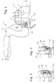
- Fig. 1
- eine Ausführungsvariante der Erfindung in einer seitlichen Ansicht;
- Fig. 2
- und
Fig. 3 Schnitte nach Linie II - II bzw. III - III inFig. 1 ; - Fig. 4
- und
Fig. 5 Details vonFig. 1 ; und - Fig. 6
- ein Diagramm zur Erklärung der Geometrie der Bauteile.
- Fig. 1
- an embodiment of the invention in a side view;
- Fig. 2
- and
Fig. 3 Sections on line II - II or III - III inFig. 1 ; - Fig. 4
- and
Fig. 5 Details ofFig. 1 ; and - Fig. 6
- a diagram explaining the geometry of the components.
Die als Handbremseinrichtung ausgebildete Feststellbremseinrichtung 1 weist einen Handbremshebel 2 mit einer Arretiervorrichtung 3 und einer Entriegelungseinrichtung 4 auf. Der beispielsweise aus Leichtmetall bestehende Handbremshebel 2 ist in einem Lagerbock 5 schwenkbar um eine Achse 6 gelagert.The
Die Arretiereinrichtung 3 besteht aus einem Sperrsegment 7 und einer mit dem Sperrsegment 4 zusammenwirkenden Sperrklinke 8, welche im Wesentlichen als ein um eine Achse 16 drehbarer Bauteil ausgebildet ist. Die Sperrklinke 8 ist mittels eines Lagerzapfens 9 drehbar im Handbremshebel 2 gelagert. Die Sperrklinke 8 weist an dem dem Sperrsegment 7 zugewandten Ende einen Sperrhaken 10 auf, der in Sperrzähne 11 des Sperrsegmentes 7 eingreift. Die Sperrklinke 8 ist über die an dem Sperrsegment 7 angreifende Entriegelungseinrichtung 4 entriegelbar, wobei die Entriegelungseinrichtung 4 im vorliegenden Beispiel eine durch eine nicht dargestellte Feder belastete, im Bremshebel 2 verschiebbar gelagerte Druckstange 13 aufweist, welche über einen Druckknopf 4 betätigbar ist.The locking device 3 consists of a
Der Anschlag 12 ist als pilzförmiger Kunststoffbauteil ausgebildet, der in einer Ausnehmung des Handbremshebels 2 formschlüssig aufgenommen ist. Wesentlich ist, dass das Material ausreichend elastisch ist, um eine Verformung von etwa 1 mm zuzulassen. Gut geeignet ist in diesem Zusammenhang beispielsweise Polyurethan, Gummi oder ein anderer ausreichend flexibler Kunststoff.The
Alternativ dazu kann die Sperrklinke 8 durch eine direkt an dieser angreifende Drehfeder in die Eingriffsrichtung vorgespannt sein, die durch Pfeil 18 dargestellt ist.Alternatively, the
Aus den
Aus den
Die Sperrklinke 8 besitzt eine Anschlagfläche 15, die einen ersten Abschnitt 25 und einen zweiten Abschnitt 27 aufweist, die durch einen konkaven Abschnitt 26 miteinander verbunden sind. Durch diese Ausbildung wird erreicht, dass sich bei Drehung um die Achse 16 die Anschlagfläche 15 im Bereich des ersten Abschnittes 25 annähernd tangential an den Anschlag 12 annähert und die erste Berührung in Form eines schleifenden Kontaktes sanft stattfindet. In weiterer Folge wandert der Berührungspunkt entlang des konkaven Abschnittes 26 zum zweiten Abschnitt 27, in dem die Berührung dann im Wesentlichen senkrecht zur lokalen Bewegungsrichtung erfolgt, so dass abgesehen von der Verformung des Anschlages 12 ein definierter Anschlagpunkt gegeben ist. Auf diese Weise wird auch bei Verwendung von weniger nachgiebigem Material am Anschlag 12 ein sanfter Eingriff der Sperrklinke 8 sichergestellt. Weiters ist aus
In dem Diagramm in der
Claims (8)
Applications Claiming Priority (1)
| Application Number | Priority Date | Filing Date | Title |
|---|---|---|---|
| AT9582007A AT505420A1 (en) | 2007-06-20 | 2007-06-20 | PARKING BRAKE DEVICE |
Publications (3)
| Publication Number | Publication Date |
|---|---|
| EP2006176A2 true EP2006176A2 (en) | 2008-12-24 |
| EP2006176A3 EP2006176A3 (en) | 2009-07-22 |
| EP2006176B1 EP2006176B1 (en) | 2010-12-01 |
Family
ID=39800467
Family Applications (1)
| Application Number | Title | Priority Date | Filing Date |
|---|---|---|---|
| EP20080158655 Expired - Fee Related EP2006176B1 (en) | 2007-06-20 | 2008-06-20 | Fixing brake device |
Country Status (3)
| Country | Link |
|---|---|
| EP (1) | EP2006176B1 (en) |
| AT (1) | AT505420A1 (en) |
| DE (1) | DE502008001920D1 (en) |
Cited By (2)
| Publication number | Priority date | Publication date | Assignee | Title |
|---|---|---|---|---|
| CN102673542A (en) * | 2012-06-12 | 2012-09-19 | 力帆实业(集团)股份有限公司 | Automotive hand brake lever |
| CN110861621A (en) * | 2019-11-13 | 2020-03-06 | 上汽大通汽车有限公司 | Automobile hand brake device with foldable handle |
Citations (4)
| Publication number | Priority date | Publication date | Assignee | Title |
|---|---|---|---|---|
| DE4321610A1 (en) | 1993-06-29 | 1995-01-19 | United Carr Gmbh Trw | Handbrake |
| EP1388471A1 (en) | 2002-08-09 | 2004-02-11 | Audi Ag | Vehicle parking brake |
| DE10324040A1 (en) | 2003-05-27 | 2005-01-05 | Adam Opel Ag | handbrake lever |
| EP1752347A2 (en) | 2005-08-12 | 2007-02-14 | Dura Global Technologies, Inc. | Ratchet type parking brake having quiet operation |
Family Cites Families (7)
| Publication number | Priority date | Publication date | Assignee | Title |
|---|---|---|---|---|
| FR2675103B1 (en) * | 1991-04-15 | 1993-08-06 | Rockwell Abs France | HAND BRAKE FOR VEHICLE. |
| JPH09226545A (en) * | 1996-02-21 | 1997-09-02 | Suzuki Motor Corp | Parking lever device for automobile |
| KR100298006B1 (en) * | 1998-06-02 | 2001-10-26 | 이충곤 | Parking brake for car |
| JP2001233188A (en) * | 2000-02-25 | 2001-08-28 | Kuroishi Tekko Kk | Parking brake device for vehicle |
| DE20210489U1 (en) * | 2002-07-06 | 2002-11-21 | Dietz Automotive Gmbh & Co Kg | Actuating device for a parking brake |
| KR20040037820A (en) * | 2002-10-30 | 2004-05-07 | 현대자동차주식회사 | apparatus for reducing operating sound of parking brake in vehicle |
| JP4844063B2 (en) * | 2004-10-13 | 2011-12-21 | 株式会社アドヴィックス | Foot-operated parking brake device for vehicles |
-
2007
- 2007-06-20 AT AT9582007A patent/AT505420A1/en not_active Application Discontinuation
-
2008
- 2008-06-20 EP EP20080158655 patent/EP2006176B1/en not_active Expired - Fee Related
- 2008-06-20 DE DE200850001920 patent/DE502008001920D1/en active Active
Patent Citations (4)
| Publication number | Priority date | Publication date | Assignee | Title |
|---|---|---|---|---|
| DE4321610A1 (en) | 1993-06-29 | 1995-01-19 | United Carr Gmbh Trw | Handbrake |
| EP1388471A1 (en) | 2002-08-09 | 2004-02-11 | Audi Ag | Vehicle parking brake |
| DE10324040A1 (en) | 2003-05-27 | 2005-01-05 | Adam Opel Ag | handbrake lever |
| EP1752347A2 (en) | 2005-08-12 | 2007-02-14 | Dura Global Technologies, Inc. | Ratchet type parking brake having quiet operation |
Cited By (2)
| Publication number | Priority date | Publication date | Assignee | Title |
|---|---|---|---|---|
| CN102673542A (en) * | 2012-06-12 | 2012-09-19 | 力帆实业(集团)股份有限公司 | Automotive hand brake lever |
| CN110861621A (en) * | 2019-11-13 | 2020-03-06 | 上汽大通汽车有限公司 | Automobile hand brake device with foldable handle |
Also Published As
| Publication number | Publication date |
|---|---|
| EP2006176A3 (en) | 2009-07-22 |
| DE502008001920D1 (en) | 2011-01-13 |
| EP2006176B1 (en) | 2010-12-01 |
| AT505420A1 (en) | 2009-01-15 |
Similar Documents
| Publication | Publication Date | Title |
|---|---|---|
| EP2347071B1 (en) | Lock unit having a multi-pawl locking mechanism | |
| EP2326781B1 (en) | Lock unit having a multi-part pawl and a spring-loaded blocking pawl | |
| EP1483515B1 (en) | Brake, especially for wind farms | |
| DE102007052060A1 (en) | knife | |
| EP3106593B1 (en) | Lock with sound insulation | |
| DE102013216721A1 (en) | Locking device with redundant springing of a blocking element | |
| EP4077982A1 (en) | Parking lock system for a motor vehicle | |
| WO2006089528A1 (en) | Door lock device | |
| DE102005035898A1 (en) | Lock with a pivot latch comprises second locking pair on the blocking link, at a short distance in front of the second locking stage | |
| EP2006176B1 (en) | Fixing brake device | |
| EP3243980B1 (en) | Locking system | |
| DE10236282B4 (en) | Motor vehicle lock with two pawls | |
| EP3438382A1 (en) | Latch assembly of a lock | |
| DE2530930A1 (en) | ATOMATIC BRAKE SHOE SEPARATION ADJUSTMENT - uses spring biased strut limiting extent of retraction | |
| EP2784248B1 (en) | Drive unit for a fitting on a connecting rod | |
| DE3034764C2 (en) | Actuating device for espagnolette fittings | |
| WO2019001898A1 (en) | Spring storage brake cylinder having an emergency release device | |
| DE202009013243U1 (en) | Actuation device for a parking brake | |
| DE3425090C1 (en) | Locking device with at least one bolt or the like. And with a lock for this bolt | |
| DE102012111364A1 (en) | Locking device for a door, preferably with a door closer | |
| EP2397717B1 (en) | Brake and/or fixing device of a slide which can be moved on a rail | |
| EP3348756B1 (en) | Closing device for a door, a window or the like | |
| DE102018006667A1 (en) | Parking brake system | |
| DE19530437C2 (en) | locking device | |
| DE102007058436B4 (en) | Hand-operated press with return stroke lock |
Legal Events
| Date | Code | Title | Description |
|---|---|---|---|
| PUAI | Public reference made under article 153(3) epc to a published international application that has entered the european phase |
Free format text: ORIGINAL CODE: 0009012 |
|
| AK | Designated contracting states |
Kind code of ref document: A2 Designated state(s): AT BE BG CH CY CZ DE DK EE ES FI FR GB GR HR HU IE IS IT LI LT LU LV MC MT NL NO PL PT RO SE SI SK TR |
|
| AX | Request for extension of the european patent |
Extension state: AL BA MK RS |
|
| PUAL | Search report despatched |
Free format text: ORIGINAL CODE: 0009013 |
|
| AK | Designated contracting states |
Kind code of ref document: A3 Designated state(s): AT BE BG CH CY CZ DE DK EE ES FI FR GB GR HR HU IE IS IT LI LT LU LV MC MT NL NO PL PT RO SE SI SK TR |
|
| AX | Request for extension of the european patent |
Extension state: AL BA MK RS |
|
| 17P | Request for examination filed |
Effective date: 20100114 |
|
| AKX | Designation fees paid |
Designated state(s): AT BE BG CH CY CZ DE DK EE ES FI FR GB GR HR HU IE IS IT LI LT LU LV MC MT NL NO PL PT RO SE SI SK TR |
|
| GRAP | Despatch of communication of intention to grant a patent |
Free format text: ORIGINAL CODE: EPIDOSNIGR1 |
|
| GRAS | Grant fee paid |
Free format text: ORIGINAL CODE: EPIDOSNIGR3 |
|
| GRAA | (expected) grant |
Free format text: ORIGINAL CODE: 0009210 |
|
| AK | Designated contracting states |
Kind code of ref document: B1 Designated state(s): DE FR |
|
| REF | Corresponds to: |
Ref document number: 502008001920 Country of ref document: DE Date of ref document: 20110113 Kind code of ref document: P |
|
| PLBE | No opposition filed within time limit |
Free format text: ORIGINAL CODE: 0009261 |
|
| STAA | Information on the status of an ep patent application or granted ep patent |
Free format text: STATUS: NO OPPOSITION FILED WITHIN TIME LIMIT |
|
| PGFP | Annual fee paid to national office [announced via postgrant information from national office to epo] |
Ref country code: FR Payment date: 20110720 Year of fee payment: 4 |
|
| 26N | No opposition filed |
Effective date: 20110902 |
|
| REG | Reference to a national code |
Ref country code: DE Ref legal event code: R097 Ref document number: 502008001920 Country of ref document: DE Effective date: 20110902 |
|
| REG | Reference to a national code |
Ref country code: FR Ref legal event code: ST Effective date: 20130228 |
|
| PG25 | Lapsed in a contracting state [announced via postgrant information from national office to epo] |
Ref country code: FR Free format text: LAPSE BECAUSE OF NON-PAYMENT OF DUE FEES Effective date: 20120702 |
|
| PGFP | Annual fee paid to national office [announced via postgrant information from national office to epo] |
Ref country code: DE Payment date: 20140528 Year of fee payment: 7 |
|
| REG | Reference to a national code |
Ref country code: DE Ref legal event code: R119 Ref document number: 502008001920 Country of ref document: DE |
|
| PG25 | Lapsed in a contracting state [announced via postgrant information from national office to epo] |
Ref country code: DE Free format text: LAPSE BECAUSE OF NON-PAYMENT OF DUE FEES Effective date: 20160101 |