EP1750035A1 - Actuator with a in a transmission housing formed support ring for radial force supporting a in transmission housing rotary mounted worm wheel - Google Patents
Actuator with a in a transmission housing formed support ring for radial force supporting a in transmission housing rotary mounted worm wheel Download PDFInfo
- Publication number
- EP1750035A1 EP1750035A1 EP05016880A EP05016880A EP1750035A1 EP 1750035 A1 EP1750035 A1 EP 1750035A1 EP 05016880 A EP05016880 A EP 05016880A EP 05016880 A EP05016880 A EP 05016880A EP 1750035 A1 EP1750035 A1 EP 1750035A1
- Authority
- EP
- European Patent Office
- Prior art keywords
- support ring
- gear
- worm wheel
- worm
- ring
- Prior art date
- Legal status (The legal status is an assumption and is not a legal conclusion. Google has not performed a legal analysis and makes no representation as to the accuracy of the status listed.)
- Withdrawn
Links
Images


Classifications
-
- F—MECHANICAL ENGINEERING; LIGHTING; HEATING; WEAPONS; BLASTING
- F16—ENGINEERING ELEMENTS AND UNITS; GENERAL MEASURES FOR PRODUCING AND MAINTAINING EFFECTIVE FUNCTIONING OF MACHINES OR INSTALLATIONS; THERMAL INSULATION IN GENERAL
- F16H—GEARING
- F16H1/00—Toothed gearings for conveying rotary motion
- F16H1/02—Toothed gearings for conveying rotary motion without gears having orbital motion
- F16H1/04—Toothed gearings for conveying rotary motion without gears having orbital motion involving only two intermeshing members
- F16H1/12—Toothed gearings for conveying rotary motion without gears having orbital motion involving only two intermeshing members with non-parallel axes
- F16H1/16—Toothed gearings for conveying rotary motion without gears having orbital motion involving only two intermeshing members with non-parallel axes comprising worm and worm-wheel
-
- E—FIXED CONSTRUCTIONS
- E05—LOCKS; KEYS; WINDOW OR DOOR FITTINGS; SAFES
- E05F—DEVICES FOR MOVING WINGS INTO OPEN OR CLOSED POSITION; CHECKS FOR WINGS; WING FITTINGS NOT OTHERWISE PROVIDED FOR, CONCERNED WITH THE FUNCTIONING OF THE WING
- E05F15/00—Power-operated mechanisms for wings
- E05F15/60—Power-operated mechanisms for wings using electrical actuators
- E05F15/603—Power-operated mechanisms for wings using electrical actuators using rotary electromotors
- E05F15/665—Power-operated mechanisms for wings using electrical actuators using rotary electromotors for vertically-sliding wings
- E05F15/689—Power-operated mechanisms for wings using electrical actuators using rotary electromotors for vertically-sliding wings specially adapted for vehicle windows
- E05F15/697—Motor units therefor, e.g. geared motors
-
- E—FIXED CONSTRUCTIONS
- E05—LOCKS; KEYS; WINDOW OR DOOR FITTINGS; SAFES
- E05Y—INDEXING SCHEME RELATING TO HINGES OR OTHER SUSPENSION DEVICES FOR DOORS, WINDOWS OR WINGS AND DEVICES FOR MOVING WINGS INTO OPEN OR CLOSED POSITION, CHECKS FOR WINGS AND WING FITTINGS NOT OTHERWISE PROVIDED FOR, CONCERNED WITH THE FUNCTIONING OF THE WING
- E05Y2900/00—Application of doors, windows, wings or fittings thereof
- E05Y2900/50—Application of doors, windows, wings or fittings thereof for vehicles
- E05Y2900/53—Application of doors, windows, wings or fittings thereof for vehicles characterised by the type of wing
- E05Y2900/55—Windows
Definitions
- the invention relates to an actuator with a drive unit and a transmission unit.
- the gear unit has a gear housing with a arranged on the inside of the housing at least segmentally formed, arranged around a driven axis support ring with at least one support surface on the support ring outside.
- the gear unit has a driven-side, about the output shaft rotatably mounted in the gear housing worm wheel, with a trained at least partially as a hollow cylinder ring gear with a toothing on the hollow cylinder outside and a bearing surface on the hollow cylinder inside.
- the gear unit further has a drive-side, about a drive axis rotatably mounted in the gear housing screw shaft, which exerts a drive force to the worm wheel in operation.
- Actuators such as power window drives or drives for actuating the sunroof in a motor vehicle, are already known. They have an electric motor and a gear unit with a worm wheel and with a gear shaft realized as a worm shaft.
- the motor unit consists of a motor housing, a brush housing and an internal rotor.
- the rotor is designed as a so-called rotor package with a variety of attached to the motor shaft slats.
- the gear shaft and motor shaft can also be made in one piece as a common drive shaft.
- the worm shaft seated at the end of the gear shaft engages and drives the worm gear. Due to the oblique flanks of the teeth of the worm wheel, the worm force introduced in the area of the worm engagement is vectorially divided into a circular and a radial force component, wherein the circular component causes the actual drive of the worm wheel and thus of the actuator.
- EP 0 869 295 A2 is a generic same actuator known.
- the device disclosed therein provides elastic damping elements for noise damping, which are in the power flow of the radially acting component of the driving force and which couple the worm wheel with a seated on the output shaft pulley.
- FIG. 5 of the EP 0 869 295 A2 is the radially acting component of the driving force via the connected to the worm gear and seated on the output shaft disc in an additional bearing shaft in the center of the worm wheel and a laterally encircling support ring in the gearbox derived.
- the object of the invention is to provide an actuator which has a simpler structure and in which the above-mentioned problems are avoided.
- the ring gear of the worm wheel is supported by a support ring so that a radially acting with respect to the output axis component of the worm is completely and torque-free introduced via the support ring in the gear housing.
- the particular advantage of the invention is that a permanently applied radially acting component of the worm force quasi directly at the point of origin, ie compared with the area of engagement of the worm shaft in the ring gear, intercepted on the same force-action line and in the transmission housing is derived. Deformation of the sprocket with gearing and engagement overlap errors is thus excluded. This avoids increasing wear and noise.
- At least one segment of the support ring protrudes at least in the area of the worm engagement at least up to the height of the drive shaft of the worm shaft into the hollow cylinder sprocket to accommodate the radially acting worm force completely and torque-free. This can also advantageously the weight of the transmission housing and thus the cost of materials for the transmission housing can be reduced.
- the width of the support surface of the support ring corresponds to at least one third of the outer diameter of the worm shaft.
- the support surface is arranged on the support ring, that the drive axis of the worm shaft is centered to the width of the support surface. In this way advantageously takes place as centric force application in the support ring.
- the ring gear of the worm wheel has a load-bearing cross-section, wherein the dimension of the supporting cross-section in the radial direction corresponds to the simple to five-fold tooth height of the toothing of the toothed wheel. This makes it advantageous to produce a more compact gear unit and thus an even more compact actuator.
- the outer diameter of the support ring is smaller than the inner diameter of the ring gear.
- the dimensions are coordinated so that between the outer diameter and inner diameter advantageously a clearance fit is generated.
- the outer diameter of the support ring has a slightly reduced value in partial areas.
- the portions with the reduced outer diameter form gaps between the support surface of the support ring and the bearing surface of the ring gear. This advantageously reduces the friction between these two surfaces.
- the friction can be further reduced if between the support surface of the support ring and the bearing surface of the ring gear a lubricant, such. a bearing grease, for lubrication of the gear, is introduced.
- a lubricant such. a bearing grease, for lubrication of the gear.
- the gaps thereby form fat pockets as a reservoir for the lubricant.
- the support ring is preferably formed as at least segmentally concentrically umlautende, wall-shaped elevation or as a cylindrical indentation of the gear housing bottom. This advantageously makes it possible to further reduce the weight of the gear unit and thus of the entire actuator.
- the worm gear at least the sprocket, a wheel disc and an output pinion or an output shaft, wherein the individual parts each rotatably connected, in particular together in one piece are formed. This advantageously reduces the number of components for an actuator.
- the gear housing and / or the worm wheel are made of a plastic, in particular of a thermoplastic, by means of an injection molding process.
- a particularly easy and cost-realizable actuator is possible.
- the plastic is e.g. a polyamide (PA) or a polypropylene (PP), so a further reduction in weight of the actuator is possible. Due to the mechanical properties of the solid polyamide, the volume of the gear housing and / or the volume of the worm wheel can be further reduced.
- PA polyamide
- PP polypropylene
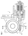
- FIG 1 shows a sectional view of an exemplary actuator 1 with a gear unit 2 and with a motor unit 4 and with a mounted in a gear housing 10 worm wheel 6 according to the invention.
- the gear housing 10 In the gear housing 10, the worm wheel 6 and an engaging in the worm wheel, designed as a worm shaft gear shaft 5 are mounted.
- the motor unit 4 consists of a motor housing and accommodated therein rotor 9 for the motor drive.
- the motor shaft is referred to, which is guided on the motor side and the transmission side in each case a motor shaft bearing 8.
- the gear shaft 5 and the worm shaft and the motor shaft 7 are made in one piece.
- the transmission shaft 5 and the motor shaft 7 can also be made in two parts and connected in rotation with each other via a coupling element.
- FIG. 2 shows a sectional view through a gear unit in the region of the engagement 18 of a worm shaft 5 in a worm wheel 6 of the transmission unit according to the prior art.
- FIG. 2 shows, in the right-hand region, a worm shaft 5 which engages in a toothing 11 of the worm wheel 6 at the point of engagement 18 and which introduces a force 6 into the worm wheel, which is referred to below as the drive force.
- the radially acting component of the driving force FR is located.
- the reference numeral 3 denotes the toothing of the worm shaft 5.
- the introduced radially acting driving force component FR is introduced on the one hand via the connected to the worm wheel and seated on the output shaft 14 disc 23 in an additional bearing shaft in the center of the worm wheel and on the other hand via a laterally encircling support ring 12 in the gear housing 10.
- the respective forces F1 and F2 introduced in the gearbox housing 10 are shown together with their respective force-effective lines W1 and W2. Bending forces or bending moments, which are received via the bearing edges and partly via the elastic damping elements 21, arise between the bearing edges due to the introduced radially acting component of the driving force FR.
- an element to be actuated by the actuator is located in an end position, such as a sunroof in the closed state, a permanent force FR is applied to the toothing of the toothed rim 11.
- the bending forces or bending moments applied in the area of the worm engagement 18 can now, in particular in heat, adversely effect a deformation of the worm wheel.
- FIG. 3A shows a sectional view through the gear unit 2 of the actuator 1 along the registered in Figure 1 section line III-III in the engagement 18 of the worm gear 3 with a support ring 12, formed as at least one segmentally concentric circumferential wall-shaped increase of the gear housing bottom according to the invention ,
- the integrally formed worm wheel 6 comprises a wheel disc 25. This results in a circumferential with respect to the output axis AB annular recess 16 between the worm wheel 6 and gear housing bottom. This recess 16 advantageously contributes to a weight saving of the gear unit 2.
- the ring gear 11 of the worm wheel 6 is now supported by a support ring 12 so that a component of the driving force FR acting radially with respect to the output axis AB is completely and momentarily introduced into the gear housing 10 via the support ring 12 with respect to the worm wheel 6 is.
- the introduced into the Gebriebegepuruse 10 force F1 is located according to their force-effective line W1 in FIG 3A. It can be seen immediately that the two forces FR and F1 lie on the same common force-action line WR / W1. Bending forces or bending moments on the ring gear 11 of the worm wheel 6 are therefore excluded.
- Voteilhaft corresponds to the width B of the support surface 19 of the support ring 12 at least one third of the outer diameter SD of the worm shaft 5.
- the width B corresponds to about 0.75.
- the ring gear 11 of the worm wheel 6 according to the invention has a load-bearing cross-section whose dimension corresponds in the radial direction T in an advantageous embodiment of the simple to five times the tooth height Z of the toothing of the ring gear 11.
- the dimension T corresponds to about three times.
- the outer diameter D of the support ring 12 is smaller than the inner diameter of the ring gear 11.
- the dimensions are coordinated so that between outer diameter D and inner diameter advantageously a clearance fit is generated.
- the outer diameter D of the support ring 12 in subregions a slightly reduced value D 'on.
- 3B shows a sectional drawing through the gear unit 2 of the actuator 1 in the region of the engagement 18 of the worm shaft 5 with a support ring 12, formed as a cylindrical indentation 26 of the gear housing bottom according to another embodiment of the invention.
- FIG. 4 shows a gear unit 2 of the actuator 1 according to FIG. 1, shown in perspective, in the opened state with partial areas 13 according to the invention of the support ring 12 with a reduced outside diameter D 'according to the invention.
- the gear housing 10 without worm wheel 6 is shown for reasons of clarity.
- a lubricant for friction reduction can be introduced between the circumferential columns 13 as partial areas with reduced outer diameter D 'and the bearing surface 17 of the ring gear 11 of the worm wheel 6, a lubricant for friction reduction can be introduced.
- the remaining between the columns 13 support surface 19 thus represents a support surface for the ring gear 11 of the worm wheel 6.
- the reference numeral 20 is an oval recess for the worm gear 3 of the worm shaft or drive shaft 5 in the gear housing 10 is designated.
Abstract
Description
Die Erfindung betrifft einen Stellantrieb mit einer Antriebseinheit und einer Getriebeeinheit. Die Getriebeeinheit weist ein Getriebegehäuse mit einem auf der Gehäuse-Innenseite angeordneten zumindest segmentweise ausgebildeten, um eine Abtriebsachse angeordneten Stützring mit zumindest einer Stützfläche auf der Stützring-Außenseite auf. Zudem weist die Getriebeeinheit ein abtriebsseitiges, um die Abtriebsachse drehbar in dem Getriebegehäuse gelagertes Schneckenrad, mit einem zumindest teilweise als Hohlzylinder ausgebildeten Zahnkranz mit einer Verzahnung auf der Hohlzylinder-Außenseite und einer Lagerfläche auf der Hohlzylinder-Innenseite auf. Die Getriebeeinheit weist weiterhin eine antriebsseitige, um eine Antriebsachse drehbar in dem Getriebegehäuse gelagerte Schneckenwelle auf, die im Betrieb eine Antriebskraft auf das Schneckenrad ausübt.The invention relates to an actuator with a drive unit and a transmission unit. The gear unit has a gear housing with a arranged on the inside of the housing at least segmentally formed, arranged around a driven axis support ring with at least one support surface on the support ring outside. In addition, the gear unit has a driven-side, about the output shaft rotatably mounted in the gear housing worm wheel, with a trained at least partially as a hollow cylinder ring gear with a toothing on the hollow cylinder outside and a bearing surface on the hollow cylinder inside. The gear unit further has a drive-side, about a drive axis rotatably mounted in the gear housing screw shaft, which exerts a drive force to the worm wheel in operation.
Stellantriebe, beispielsweise Fensterheber-Antriebe oder Antriebe zur Betätigung des Schiebedaches in einem Kraftfahrzeug, sind bereits bekannt. Sie weisen einen Elektromotor sowie eine Getriebeeinheit mit einem Schneckenrad und mit einer als Schneckenwelle realisierte Getriebewelle auf. Die Motoreinheit besteht aus einem Motorgehäuse, einem Bürstengehäuse und einem innenliegenden Läufer. Der Läufer ist dabei als so genanntes Läuferpaket mit einer Vielzahl von auf der Motorwelle befestigten Lamellen ausgebildet. Die Getriebewelle und Motorwelle können auch als gemeinsame Antriebswelle einteilig ausgeführt sein.Actuators, such as power window drives or drives for actuating the sunroof in a motor vehicle, are already known. They have an electric motor and a gear unit with a worm wheel and with a gear shaft realized as a worm shaft. The motor unit consists of a motor housing, a brush housing and an internal rotor. The rotor is designed as a so-called rotor package with a variety of attached to the motor shaft slats. The gear shaft and motor shaft can also be made in one piece as a common drive shaft.
Die am Ende der Getriebewelle sitzende Schneckenwelle steht im Eingriff mit dem Schneckenrad und treibt dieses an. Durch die schrägen Flanken der Zähne des Schneckenrads wird die im Bereich des Schneckeneingriffs eingeleitete Schneckenkraft vektoriell in eine zirkulare und in eine radiale Kraftkomponente aufgeteilt, wobei die zirkulare Komponente den eigentlichen Antrieb des Schneckenrads und somit des Stellantriebs bewirkt.The worm shaft seated at the end of the gear shaft engages and drives the worm gear. Due to the oblique flanks of the teeth of the worm wheel, the worm force introduced in the area of the worm engagement is vectorially divided into a circular and a radial force component, wherein the circular component causes the actual drive of the worm wheel and thus of the actuator.
Aus der
Befindet sich allerdings ein durch den Stellantrieb zu betätigendes Element, wie z.B. ein Seitenfenster oder ein Schiebedach eines Kraftfahrzeugs, in einer Endlage, wie z.B. im geschlossenen Zustand, so liegt an der Verzahnung des Schneckenrads eine ständige Schneckenkraft an. Problematisch ist dieser Zustand dann, wenn es insbesondere bei Hitze zu einer Verformung des üblicherweise aus einem Kunststoff gefertigten Schneckenrads kommt. Das Schneckenrad wird dann über die im Bereich des Eingriffs radial wirkende Komponente der Schneckenkraft in gewissen Umfang eingedellt. Die dabei so entstandene Verformung führt zu einem ungleichmäßigen Lauf sowie zu Verzahnungsfehlern mit einer fehlerhaften Eingriffsüberdeckung. Eine Verkürzung der Lebensdauer des Stellantriebs durch Verschleiß ist die Folge.However, if an element to be actuated by the actuator, such as a side window or a sunroof of a motor vehicle, is in an end position, such as in the closed state, then a constant screw force is applied to the toothing of the worm wheel. This condition is problematic when it comes to deformation of the usually made of a plastic worm wheel, especially in heat. The worm wheel is then indented to a certain extent via the component of the worm force acting radially in the area of the engagement. The resulting deformation leads to an uneven run as well To gear errors with a faulty engagement overlap. A shortening of the life of the actuator by wear is the result.
Die oben genannten Probleme werden durch den in der
Die Aufgabe der Erfindung besteht darin, einen Stellantrieb anzugeben, welcher einen einfacheren Aufbau aufweist und bei welchem die oben genannten Probleme vermieden werden.The object of the invention is to provide an actuator which has a simpler structure and in which the above-mentioned problems are avoided.
Diese Aufgabe wird durch einen Stellantrieb mit den im Anspruch 1 angegebenen Merkmalen gelöst. Vorteilhafte Ausgestaltungen und Weiterbildungen der Erfindung ergeben sich aus den abhängigen Ansprüchen 2 bis 10.This object is achieved by an actuator with the features specified in claim 1. Advantageous embodiments and further developments of the invention will become apparent from the
Bei dem erfindungsgemäßen Stellantrieb wird der Zahnkranz des Schneckenrads durch einen Stützring so abgestützt, dass eine in Bezug auf die Abtriebsachse radial wirkende Komponente der Schneckenkraft vollständig und momentenfrei über den Stützring in das Getriebegehäuse eingeleitet ist.In the actuator according to the invention, the ring gear of the worm wheel is supported by a support ring so that a radially acting with respect to the output axis component of the worm is completely and torque-free introduced via the support ring in the gear housing.
Der besondere Vorteil der Erfindung liegt darin, dass eine dauerhaft anstehende radial wirkende Komponente der Schneckenkraft quasi direkt am Entstehungsort, d.h. gegenüber dem Bereich des Eingriffs der Schneckenwelle im Zahnkranz, auf gleicher Kraft-Wirklinie abgefangen und in das Getriebegehäuse abgeleitet wird. Eine Verformung des Zahnkranzes mit Verzahnungs- und Eingriffsüberdeckungsfehler ist somit ausgeschlossen. Dadurch werden ein zunehmender Verschleiß und eine zunehmende Geräuschentwicklung vermieden.The particular advantage of the invention is that a permanently applied radially acting component of the worm force quasi directly at the point of origin, ie compared with the area of engagement of the worm shaft in the ring gear, intercepted on the same force-action line and in the transmission housing is derived. Deformation of the sprocket with gearing and engagement overlap errors is thus excluded. This avoids increasing wear and noise.
In einer Ausführungsform ragt zumindest ein Segment des Stützringes zumindest im Bereich des Schneckeneingriffs mindestens bis auf Höhe der Antriebsachse der Schneckenwelle in den Hohlzylinder-Zahnkranz hineinragt, um die radial wirkende Schneckenkraft vollständig und momentenfrei aufzunehmen. Dadurch kann zudem vorteilhaft das Gewicht des Getriebegehäuses und somit der Materialaufwand für das Getriebegehäuse reduziert werden.In one embodiment, at least one segment of the support ring protrudes at least in the area of the worm engagement at least up to the height of the drive shaft of the worm shaft into the hollow cylinder sprocket to accommodate the radially acting worm force completely and torque-free. This can also advantageously the weight of the transmission housing and thus the cost of materials for the transmission housing can be reduced.
Insbesondere entspricht die Breite der Stützfläche des Stützringes mindestens einem Drittel des Außendurchmessers der Schneckenwelle. Dadurch ist eine vorteilhaft kompaktere Bauweise des Getriebegehäuses möglich.In particular, the width of the support surface of the support ring corresponds to at least one third of the outer diameter of the worm shaft. As a result, an advantageous compact design of the transmission housing is possible.
In einer Ausführungsform ist die Stützfläche so auf dem Stützring angeordnet ist, dass die Antriebsachse der Schneckenwelle mittig zur Breite der Stützfläche liegt. Auf diese Weise erfolgt vorteilhaft eine möglichst zentrische Krafteinleitung in den Stützring.In one embodiment, the support surface is arranged on the support ring, that the drive axis of the worm shaft is centered to the width of the support surface. In this way advantageously takes place as centric force application in the support ring.
Vorzugsweise weist der Zahnkranz des Schneckenrades einen tragenden Querschnitt auf, wobei die Abmessung des tragenden Querschnittes in radialer Richtung der einfachen bis fünffachen Zahnhöhe der Verzahnung des Zahnrades entspricht. Dadurch lässt sich vorteilhaft eine noch kompaktere Getriebeeinheit und somit ein noch kompakterer Stellantrieb herstellen.Preferably, the ring gear of the worm wheel has a load-bearing cross-section, wherein the dimension of the supporting cross-section in the radial direction corresponds to the simple to five-fold tooth height of the toothing of the toothed wheel. This makes it advantageous to produce a more compact gear unit and thus an even more compact actuator.
In einer bevorzugten Ausführungsform ist der Außendurchmesser des Stützringes kleiner als der Innendurchmesser des Zahnkranzes. Zudem sind die Abmessungen so aufeinander abgestimmt, dass zwischen Außendurchmesser und Innendurchmesser vorteilhaft eine Spielpassung erzeugt ist.In a preferred embodiment, the outer diameter of the support ring is smaller than the inner diameter of the ring gear. In addition, the dimensions are coordinated so that between the outer diameter and inner diameter advantageously a clearance fit is generated.
In einer weiteren Ausführungsform weist der Außendurchmesser des Stützringes in Teilbereichen einen geringfügig reduzierten Wert auf. Die Teilbereiche mit dem reduzierten Außendurchmesser bilden Spalte zwischen der Stützfläche des Stützringes und der der Lagerfläche des Zahnkranzes aus. Dadurch wird die Reibung zwischen diesen beiden Flächen vorteilhaft reduziert.In a further embodiment, the outer diameter of the support ring has a slightly reduced value in partial areas. The portions with the reduced outer diameter form gaps between the support surface of the support ring and the bearing surface of the ring gear. This advantageously reduces the friction between these two surfaces.
Insbesondere kann die Reibung weiterhin reduziert werden, wenn zwischen der Stützfläche des Stützrings und der Lagerfläche des Zahnkranzes ein Schmiermittel, wie z.B. ein Lagerfett, zur Schmierung des Zahnrads, eingebracht ist. Die Spalte bilden dabei Fetttaschen als ein Reservoir für das Schmiermittel.In particular, the friction can be further reduced if between the support surface of the support ring and the bearing surface of the ring gear a lubricant, such. a bearing grease, for lubrication of the gear, is introduced. The gaps thereby form fat pockets as a reservoir for the lubricant.
Der Stützring ist vorzugsweise als zumindest segmentweise konzentrisch umlautende, wandförmige Erhöhung oder als eine zylinderförmige Einformung des Getriebegehäusebodens ausgebildet. Dadurch lässt sich vorteilhaft das Gewicht der Getriebeeinheit und somit des gesamten Stellantriebs weiter reduzieren.The support ring is preferably formed as at least segmentally concentrically umlautende, wall-shaped elevation or as a cylindrical indentation of the gear housing bottom. This advantageously makes it possible to further reduce the weight of the gear unit and thus of the entire actuator.
In einer weiteren Ausführungsform weist das Schneckenrad zumindest den Zahnkranz, eine Radscheibe und ein Abtriebsritzel oder eine Abtriebswelle auf, wobei die einzelnen Teile jeweils drehfest verbunden, insbesondere zusammen einstückig ausgeformt sind. Dadurch wird vorteilhaft die Bauteilanzahl für einen Stellantrieb reduziert.In a further embodiment, the worm gear at least the sprocket, a wheel disc and an output pinion or an output shaft, wherein the individual parts each rotatably connected, in particular together in one piece are formed. This advantageously reduces the number of components for an actuator.
In einer bevorzugten Ausführungsform sind das Getriebegehäuse und/oder das Schneckenrad aus einem Kunststoff, insbesondere aus einem Thermoplast, mittels eines Spritzgussverfahrens hergestellt. Dadurch ist ein besonders leichter und kostengünstig realisierbarer Stellantrieb möglich.In a preferred embodiment, the gear housing and / or the worm wheel are made of a plastic, in particular of a thermoplastic, by means of an injection molding process. As a result, a particularly easy and cost-realizable actuator is possible.
Ist der Kunststoff z.B. ein Polyamid (PA) oder ein Polypropylen (PP), so ist eine weitere Gewichtsreduzierung des Stellantriebs möglich. Durch die in mechanischer Hinsicht festen Eigenschaften des Polyamids kann das Bauvolumen des Getriebegehäuses und/oder das Bauvolumen des Schneckenrads weiter verringert werden.If the plastic is e.g. a polyamide (PA) or a polypropylene (PP), so a further reduction in weight of the actuator is possible. Due to the mechanical properties of the solid polyamide, the volume of the gear housing and / or the volume of the worm wheel can be further reduced.
Weitere vorteilhafte Eigenschaften der Erfindung ergeben sich aus deren beispielhafter Erläuterung anhand der Figuren. Es zeigt:
- FIG 1
- eine Schnittzeichnung eines beispielhaften Stellantriebs mit einer Getriebeeinheit und mit einer Motoreinheit sowie mit einem in einem Getriebegehäuse gelagerten Schneckenrad gemäß der Erfindung,
- FIG 2
- eine Schnittzeichnung durch eine Getriebeeinheit im Bereich des Eingriffs einer Schneckenwelle in ein Schneckenrad der Getriebeeinheit nach dem Stand der Technik,
- FIG 3A
- eine Schnittzeichnung durch die Getriebeeinheit des Stellantriebs entlang der in FIG 1 eingetragenen Schnittlinie IIIA im Bereich des Eingriffs der Schneckenwelle mit einem Stützring, ausgebildet als zumindest eine segmentweise konzentrisch umlaufende, wandförmige Erhöhung des Getriebegehäusebodens gemäß der Erfindung,
- FIG 3B
- eine Schnittzeichnung durch die Getriebeeinheit des Stellantriebs im Bereich des Eingriffs der Schneckenwelle mit einem Stützring, ausgebildet als eine zylinderförmige Einformung des Getriebegehäusebodens gemäß einer weiteren Ausführungsform der Erfindung, und
- FIG 4
- eine perspektiv dargestellte Getriebeeinheit des Stellantriebs gemäß FIG 1 im geöffneten Zustand mit erfindungsgemäßen Teilbereichen des Stützringes mit einem reduzierten Außendurchmesser gemäß der Erfindung.
- FIG. 1
- a sectional view of an exemplary actuator with a gear unit and a motor unit and with a mounted in a gear housing worm wheel according to the invention,
- FIG. 2
- a sectional view through a gear unit in the region of engagement of a worm shaft in a worm wheel of the transmission unit according to the prior art,
- 3A
- a sectional view through the gear unit of the actuator along the registered in Figure 1 section line IIIA in the region of engagement of the worm shaft with a support ring, formed as at least one segmental concentric circumferential, wall-shaped increase of the gear housing bottom according to the invention,
- 3B
- a sectional view through the gear unit of the actuator in the region of engagement of the worm shaft with a support ring, formed as a cylindrical indentation of the gear housing bottom according to a further embodiment of the invention, and
- FIG. 4
- 1 in the open state with partial areas according to the invention of the support ring with a reduced outer diameter according to the invention.
FIG 1 zeigt eine Schnittzeichnung eines beispielhaften Stellantriebs 1 mit einer Getriebeeinheit 2 und mit einer Motoreinheit 4 sowie mit einem in einem Getriebegehäuse 10 gelagerten Schneckenrad 6 gemäß der Erfindung. Im Getriebegehäuse 10 sind das Schneckenrad 6 sowie eine in das Schneckenrad eingreifende, als Schneckenwelle ausgebildete Getriebewelle 5 gelagert. Die Motoreinheit 4 besteht aus einem Motorgehäuse und einem darin untergebrachten Läufer 9 für den motorischen Antrieb. Mit dem Bezugszeichen 7 ist die Motorwelle bezeichnet, welche motorseitig und getriebeseitig in je einem Motorwellenlager 8 geführt ist. Im Beispiel der FIG 1 sind die Getriebewelle 5 bzw. die Schneckenwelle und die Motorwelle 7 einteilig ausgeführt. Alternativ können die Getriebewelle 5 und die Motorwelle 7 auch zweiteilig ausgeführt und über ein Kupplungselement drehfest miteinander verbunden sein.1 shows a sectional view of an exemplary actuator 1 with a
FIG 2 zeigt eine Schnittzeichnung durch eine Getriebeeinheit im Bereich des Eingriffs 18 einer Schneckenwelle 5 in ein Schneckenrad 6 der Getriebeeinheit nach dem Stand der Technik. Die FIG 2 zeigt im rechten Bereich eine Schneckenwelle 5, welche im Eingriffspunkt 18 in ein Verzahnung 11 des Schneckenrads 6 eingreift und welche eine Kraft 6 in das Schneckenrad einleitet, die im Folgenden als Antriebskraft bezeichnet wird. Im Beispiel der FIG 2 ist die radial wirkende Komponente der Antriebskraft FR eingezeichnet. Mit dem Bezugszeichen 3 ist die Verzahnung der Schneckenwelle 5 bezeichnet.2 shows a sectional view through a gear unit in the region of the
Die eingeleitete radial wirkende Antriebskraftkomponente FR wird dabei einerseits über die mit dem Schneckenrad verbundene und auf der Abtriebswelle 14 sitzende Scheibe 23 in eine zusätzliche Lagerwelle im Zentrum des Schneckenrads und andererseits über einen seitlich umlaufenden Stützring 12 im Getriebegehäuse 10 eingeleitet. In der FIG 2 sind dazu die jeweiligen im Getriebegehäuse 10 eingeleiteten Kräfte F1 und F2 zusammen mit ihrer jeweiligen Kraft-Wirklinie W1 und W2 eingezeichnet. Zwischen den Auflagekanten entstehen durch die eingeleitete radial wirkende Komponente der Antriebskraft FR Biegekräfte bzw. Biegemomente, die über die Auflagekanten sowie zum Teil über die elastischen Dämpfungselemente 21 aufgenommen werden.The introduced radially acting driving force component FR is introduced on the one hand via the connected to the worm wheel and seated on the
Befindet sich, wie eingangs beschrieben, nun ein durch den Stellantrieb zu betätigendes Element in einer Endlage, wie z.B. ein Schiebedach im geschlossenen Zustand, so wird eine ständige Kraft FR auf die Verzahnung des Zahnkranzes 11 aufgebracht. Die im Bereich des Schneckeneingriffs 18 aufgebrachten Biegekräfte bzw. Biegemomente können nun, insbesondere bei Hitze, nachteilig eine Verformung des Schneckenrads bewirken.If, as described in the introduction, an element to be actuated by the actuator is located in an end position, such as a sunroof in the closed state, a permanent force FR is applied to the toothing of the
FIG 3A zeigt eine Schnittzeichnung durch die Getriebeeinheit 2 des Stellantriebs 1 entlang der in FIG 1 eingetragenen Schnittlinie III-III im Bereich des Eingriffs 18 der Schneckenverzahnung 3 mit einem Stützring 12, ausgebildet als zumindest eine segmentweise konzentrisch umlaufende, wandförmige Erhöhung des Getriebegehäusebodens gemäß der Erfindung.3A shows a sectional view through the
Entsprechend der vorliegenden FIG 3A umfasst das einstückig ausgebildete Schneckenrad 6 eine Radscheibe 25. Dadurch entsteht eine im Bezug auf die Abtriebsachse AB umlaufende ringförmige Aussparung 16 zwischen Schneckenrad 6 und Getriebegehäuseboden. Diese Aussparung 16 trägt vorteilhaft zu einer Gewichtsersparnis der Getriebeeinheit 2 bei.According to the present FIG 3A, the integrally formed
Gemäß der Erfindung ist nun der Zahnkranz 11 des Schneckenrads 6 durch einen Stützring 12 so abgestützt, dass eine in Bezug auf die Abtriebsachse AB radial wirkende Komponente der Antriebskraft FR vollständig und in Bezug auf das Schneckerad 6 momentenfrei über den Stützring 12 in das Getriebegehäuse 10 eingeleitet ist. Die in das Gebriebegehäuse 10 eingeleitete Kraft F1 ist entsprechend ihrer Kraft-Wirklinie W1 in der FIG 3A eingezeichnet. Es ist unmittelbar erkennbar, dass die beiden Kräfte FR und F1 auf einer gleichen gemeinsamen Kraft-Wirklinie WR/W1 liegen. Biegekräfte bzw. Biegemomente am Zahnkranz 11 des Schneckenrades 6 sind folglich ausgeschlossen.According to the invention, the
Voteilhaft entspricht die Breite B der Stützfläche 19 des Stützringes 12 mindestens einem Drittel des Außendurchmessers SD der Schneckenwelle 5. Im Beispiel der FIG 3A entspricht die Breite B ca. 0,75.Voteilhaft corresponds to the width B of the
Weiterhin weist der Zahnkranz 11 des Schneckenrades 6 gemäß der Erfindung einen tragenden Querschnitt auf, dessen Abmessung in radialer Richtung T in vorteilhafter Ausführung der einfachen bis fünffachen Zahnhöhe Z der Verzahnung des Zahnkranzes 11 entspricht. Im Beispiel der FIG 3A entspricht die Abmessung T etwa dem dreifachen.Furthermore, the
Wie die vorliegende FIG 3A zeigt, ist gemäß der Erfindung der Außendurchmesser D des Stützringes 12 kleiner als der Innendurchmesser des Zahnkranzes 11. Die Abmessungen sind dabei so aufeinander abgestimmt, dass zwischen Außendurchmesser D und Innendurchmesser vorteilhaft eine Spielpassung erzeugt ist.As the present FIG 3A shows, according to the invention, the outer diameter D of the
Einer Ausführungsform der Erfindung entsprechend weist der Außendurchmesser D des Stützringes 12 in Teilbereichen einen geringfügig reduzierten Wert D' auf. Die Teilbereiche mit dem reduzierten Außendurchmesser D' bilden Spalte 13 zwischen der Stützfläche 19 des Stützringes 12 und der Lagerfläche 17 des Zahnkranzes 11 aus. Dadurch wird die Reibung zwischen diesen beiden Flächen vorteilhaft reduziert.According to an embodiment of the invention, the outer diameter D of the
FIG 3B zeigt eine Schnittzeichnung durch die Getriebeeinheit 2 des Stellantriebs 1 im Bereich des Eingriffs 18 der Schneckenwelle 5 mit einem Stützring 12, ausgebildet als eine zylinderförmige Einformung 26 des Getriebegehäusebodens gemäß einer weiteren Ausführungsform der Erfindung.3B shows a sectional drawing through the
Im Vergleich zur vorherigen FIG 3A wird eine weitere Gewichtsersparnis der Getriebeeinheit 2 dadurch erzielt, dass sich durch die zylinderförmige Einformung 26 nun eine zylinderförmige Aussparung 27 im Getriebegehäuseboden ausbildet, deren Volumen größer ist als im Vergleich zur ringförmigen Aussparung 16 gemäß FIG 3A.In comparison to the previous FIG. 3A, a further weight saving of the
FIG 4 zeigt eine perspektiv dargestellte Getriebeeinheit 2 des Stellantriebs 1 gemäß FIG 1 im geöffneten Zustand mit erfindungsgemäßen Teilbereichen 13 des Stützrings 12 mit einem reduzierten Außendurchmesser D' gemäß der Erfindung. Im Beispiel der FIG 4 ist zudem aus Gründen der Übersichtlichkeit das Getriebegehäuse 10 ohne Schneckenrad 6 dargestellt.FIG. 4 shows a
Gemäß der Erfindung kann insbesondere zwischen den umlaufenden Spalten 13 als Teilbereiche mit reduziertem Außendurchmesser D' und der Lagerfläche 17 des Zahnkranzes 11 des Schneckenrads 6 ein Schmiermittel zur Reibungsverminderung eingebracht werden. Die zwischen den Spalten 13 verbleibende Stützfläche 19 stellt somit eine Tragfläche für den Zahnkranz 11 des Schneckenrads 6 dar. Mit dem Bezugszeichen 20 ist eine ovale Aussparung für die Schneckenverzahnung 3 der Schneckenwelle bzw. Antriebswelle 5 im Getriebegehäuse 10 bezeichnet.According to the invention, in particular between the
Claims (10)
dass der Zahnkranz (11) des Schneckenrades (6) mit seiner Lagerfläche (17) auf der Stützfläche (19) des Stützringes (12) gleitend gelagert ist, und
dass zumindest ein Segment des Stützringes (12) zumindest im Bereich des Schneckeneingriffs (18) so weil in den Zahnkranz (11) hineinragt, dass eine in Bezug auf die Abtriebsachse (AB) radial wirkende Komponente der Antriebskraft (FR) auf gleicher, gerader Wirklinie (WR/W1) über den Zahnkranz (11) des Schneckenrads (6) in den Stützring (12) des Gehäuses (10) eingeleitet ist.Actuator with a drive unit (4) and a gear unit (2), wherein the gear unit (2) comprises:
that the ring gear (11) of the worm wheel (6) with its bearing surface (17) on the support surface (19) of the support ring (12) is slidably mounted, and
that at least a segment of the support ring (12) at least in the region of the screw engagement (18) so as to protrude into the ring gear (11) that with respect to the output shaft (AB) radially acting component of the driving force (FR) on the same straight line of action (WR / W1) via the ring gear (11) of the worm wheel (6) in the support ring (12) of the housing (10) is initiated.
Priority Applications (2)
| Application Number | Priority Date | Filing Date | Title |
|---|---|---|---|
| EP05016880A EP1750035A1 (en) | 2005-08-03 | 2005-08-03 | Actuator with a in a transmission housing formed support ring for radial force supporting a in transmission housing rotary mounted worm wheel |
| PCT/EP2006/064265 WO2007014836A1 (en) | 2005-08-03 | 2006-07-14 | Adjusting drive having a support ring, which is formed in the gearing housing, for radially supporting the force of a worm gear which is mounted in the gearing housing |
Applications Claiming Priority (1)
| Application Number | Priority Date | Filing Date | Title |
|---|---|---|---|
| EP05016880A EP1750035A1 (en) | 2005-08-03 | 2005-08-03 | Actuator with a in a transmission housing formed support ring for radial force supporting a in transmission housing rotary mounted worm wheel |
Publications (1)
| Publication Number | Publication Date |
|---|---|
| EP1750035A1 true EP1750035A1 (en) | 2007-02-07 |
Family
ID=35482207
Family Applications (1)
| Application Number | Title | Priority Date | Filing Date |
|---|---|---|---|
| EP05016880A Withdrawn EP1750035A1 (en) | 2005-08-03 | 2005-08-03 | Actuator with a in a transmission housing formed support ring for radial force supporting a in transmission housing rotary mounted worm wheel |
Country Status (2)
| Country | Link |
|---|---|
| EP (1) | EP1750035A1 (en) |
| WO (1) | WO2007014836A1 (en) |
Citations (6)
| Publication number | Priority date | Publication date | Assignee | Title |
|---|---|---|---|---|
| US4766777A (en) * | 1986-06-05 | 1988-08-30 | The United States Of America As Represented By The Secretary Of The Army | Interrupted thread lock mechanism for an engine-transmission assembly |
| EP0869295A2 (en) | 1997-04-02 | 1998-10-07 | Mabuchi Motor Kabushiki Kaisha | Motor assembly with reduction gear |
| EP1134181A2 (en) * | 2000-03-14 | 2001-09-19 | Roncari S.r.l. | Rotation device for working units in lift trucks or the like |
| JP2003056651A (en) * | 2001-08-17 | 2003-02-26 | Jidosha Denki Kogyo Co Ltd | Motor with speed reducing mechanism |
| JP2004068878A (en) * | 2002-08-05 | 2004-03-04 | Nsk Ltd | Clutch device |
| JP2004135403A (en) * | 2002-10-09 | 2004-04-30 | Jidosha Denki Kogyo Co Ltd | Motor with electromagnetic clutch |
Family Cites Families (3)
| Publication number | Priority date | Publication date | Assignee | Title |
|---|---|---|---|---|
| FR56068E (en) * | 1945-11-07 | 1952-09-12 | Jaeger Ets Ed | Improvements to speedometers for cycles and motorcycles, to their control means and to their means of mounting on these vehicles |
| ES225001Y (en) * | 1976-12-09 | 1977-11-16 | FORWARDING FOR MOTORCYCLES. | |
| DE10046236A1 (en) * | 2000-02-09 | 2001-08-16 | Bosch Gmbh Robert | Gear drive unit, in particular for motor vehicle adjustment devices |
-
2005
- 2005-08-03 EP EP05016880A patent/EP1750035A1/en not_active Withdrawn
-
2006
- 2006-07-14 WO PCT/EP2006/064265 patent/WO2007014836A1/en active Application Filing
Patent Citations (6)
| Publication number | Priority date | Publication date | Assignee | Title |
|---|---|---|---|---|
| US4766777A (en) * | 1986-06-05 | 1988-08-30 | The United States Of America As Represented By The Secretary Of The Army | Interrupted thread lock mechanism for an engine-transmission assembly |
| EP0869295A2 (en) | 1997-04-02 | 1998-10-07 | Mabuchi Motor Kabushiki Kaisha | Motor assembly with reduction gear |
| EP1134181A2 (en) * | 2000-03-14 | 2001-09-19 | Roncari S.r.l. | Rotation device for working units in lift trucks or the like |
| JP2003056651A (en) * | 2001-08-17 | 2003-02-26 | Jidosha Denki Kogyo Co Ltd | Motor with speed reducing mechanism |
| JP2004068878A (en) * | 2002-08-05 | 2004-03-04 | Nsk Ltd | Clutch device |
| JP2004135403A (en) * | 2002-10-09 | 2004-04-30 | Jidosha Denki Kogyo Co Ltd | Motor with electromagnetic clutch |
Non-Patent Citations (2)
| Title |
|---|
| PATENT ABSTRACTS OF JAPAN vol. 2003, no. 06 3 June 2003 (2003-06-03) * |
| PATENT ABSTRACTS OF JAPAN vol. 2003, no. 12 5 December 2003 (2003-12-05) * |
Also Published As
| Publication number | Publication date |
|---|---|
| WO2007014836A1 (en) | 2007-02-08 |
Similar Documents
| Publication | Publication Date | Title |
|---|---|---|
| DE69721523T2 (en) | TRANSMISSION MOTOR, IN PARTICULAR FOR DRIVING ACCESSORIES IN MOTOR VEHICLES | |
| DE102016207930B3 (en) | The wave gear | |
| WO2015021972A2 (en) | Adjusting device | |
| DE102006010268B4 (en) | Helical gear for rack and pinion steering | |
| DE102005018956A1 (en) | Device for adjusting the camshaft of an internal combustion engine | |
| DE102015217164B4 (en) | Assembly with a friction device | |
| DE102014107073A1 (en) | steering gear | |
| DE102015220920B4 (en) | Assembly with a friction device | |
| DE102017126527A1 (en) | The wave gear | |
| DE102017119860A1 (en) | The wave gear | |
| WO2009118218A1 (en) | Device for reducing rattling noise in multi-speed manual transmissions | |
| DE102019209470A1 (en) | Parking lock arrangement with parking lock gear and torsion damper | |
| EP3426541B1 (en) | Steering gear | |
| DE10315151A1 (en) | Device for relative angular displacement of a camshaft relative to the driving drive wheel | |
| DE102007057391A1 (en) | Toothed rack servo steering mechanism for motor vehicle, has elastic connection unit forming part of coupling over which rotor and ball nut of ball screw are fixedly connected in movable manner relative to each other in axial direction | |
| DE102004003664B3 (en) | Final control device, e.g. for controlling flaps in internal combustion engines, has worm wheel as segment with at least one sprung stop with stop surface that rests against corresponding stop surface on worm or worm shaft in end position | |
| DE102006028777A1 (en) | Hydrodynamic torque converter, has turbine, and torsion damper with three sheet plates, where extensions protruding via recesses of one sheet plate and turbine deform against each other between turbine sided axial stops and sections | |
| EP1750035A1 (en) | Actuator with a in a transmission housing formed support ring for radial force supporting a in transmission housing rotary mounted worm wheel | |
| DE102020129285A1 (en) | Expansion valve | |
| DE102020129738A1 (en) | Harmonic gearing, method for producing harmonic gearing and internal combustion engine with camshaft adjusters having harmonic gearing | |
| DE102008055070A1 (en) | Drive unit for operation of radial piston pumps of hydraulic unit of electronically slip-adjustable brake system of motor vehicle, has drive motor with motor shaft and eccentric devices mounted on motor shaft | |
| DE102004058177B4 (en) | gear | |
| DE102017216107A1 (en) | Active roll stabilizer for a motor vehicle | |
| DE102009046644A1 (en) | Power steering, particularly power steering for vehicle, has movement screw propelled by servo actuator from nut axially supported in rack and axially shiftable construction element | |
| DE102009035346A1 (en) | Drive shaft-transmission connection for side shaft of motor vehicle, has ring that struts flange and joint axially against each other, in one of relative positions of ring to flange and joint attained by twist |
Legal Events
| Date | Code | Title | Description |
|---|---|---|---|
| PUAI | Public reference made under article 153(3) epc to a published international application that has entered the european phase |
Free format text: ORIGINAL CODE: 0009012 |
|
| AK | Designated contracting states |
Kind code of ref document: A1 Designated state(s): AT BE BG CH CY CZ DE DK EE ES FI FR GB GR HU IE IS IT LI LT LU LV MC NL PL PT RO SE SI SK TR |
|
| AX | Request for extension of the european patent |
Extension state: AL BA HR MK YU |
|
| 17P | Request for examination filed |
Effective date: 20070806 |
|
| AKX | Designation fees paid |
Designated state(s): DE FR GB IT |
|
| 17Q | First examination report despatched |
Effective date: 20071001 |
|
| STAA | Information on the status of an ep patent application or granted ep patent |
Free format text: STATUS: THE APPLICATION HAS BEEN WITHDRAWN |
|
| 18W | Application withdrawn |
Effective date: 20071217 |