EP1749711A2 - A motor vehicle with a front bonnet for pedestrian protection - Google Patents
A motor vehicle with a front bonnet for pedestrian protection Download PDFInfo
- Publication number
- EP1749711A2 EP1749711A2 EP20060270065 EP06270065A EP1749711A2 EP 1749711 A2 EP1749711 A2 EP 1749711A2 EP 20060270065 EP20060270065 EP 20060270065 EP 06270065 A EP06270065 A EP 06270065A EP 1749711 A2 EP1749711 A2 EP 1749711A2
- Authority
- EP
- European Patent Office
- Prior art keywords
- latch
- release
- bonnet
- vehicle
- actuator
- Prior art date
- Legal status (The legal status is an assumption and is not a legal conclusion. Google has not performed a legal analysis and makes no representation as to the accuracy of the status listed.)
- Granted
Links
Images




Classifications
-
- B—PERFORMING OPERATIONS; TRANSPORTING
- B60—VEHICLES IN GENERAL
- B60R—VEHICLES, VEHICLE FITTINGS, OR VEHICLE PARTS, NOT OTHERWISE PROVIDED FOR
- B60R21/00—Arrangements or fittings on vehicles for protecting or preventing injuries to occupants or pedestrians in case of accidents or other traffic risks
- B60R21/34—Protecting non-occupants of a vehicle, e.g. pedestrians
- B60R21/38—Protecting non-occupants of a vehicle, e.g. pedestrians using means for lifting bonnets
-
- B—PERFORMING OPERATIONS; TRANSPORTING
- B60—VEHICLES IN GENERAL
- B60R—VEHICLES, VEHICLE FITTINGS, OR VEHICLE PARTS, NOT OTHERWISE PROVIDED FOR
- B60R21/00—Arrangements or fittings on vehicles for protecting or preventing injuries to occupants or pedestrians in case of accidents or other traffic risks
- B60R21/34—Protecting non-occupants of a vehicle, e.g. pedestrians
-
- Y—GENERAL TAGGING OF NEW TECHNOLOGICAL DEVELOPMENTS; GENERAL TAGGING OF CROSS-SECTIONAL TECHNOLOGIES SPANNING OVER SEVERAL SECTIONS OF THE IPC; TECHNICAL SUBJECTS COVERED BY FORMER USPC CROSS-REFERENCE ART COLLECTIONS [XRACs] AND DIGESTS
- Y10—TECHNICAL SUBJECTS COVERED BY FORMER USPC
- Y10T—TECHNICAL SUBJECTS COVERED BY FORMER US CLASSIFICATION
- Y10T292/00—Closure fasteners
- Y10T292/08—Bolts
- Y10T292/1043—Swinging
- Y10T292/1044—Multiple head
- Y10T292/1045—Operating means
- Y10T292/1047—Closure
Definitions
- the present invention relates to a motor vehicle having a vehicle bonnet assembly and in particular to a vehicle bonnet assembly providing improved pedestrian safety.
- GB 2 382 548 which shows a vehicle bonnet assembly including a bonnet hinged at its front and latched at its rear, two latch assemblies respectively engageable with a striker on the bonnet.
- Each latch assembly is mounted to the vehicle body by a shear pin and is connected to a pyrotechnic cylinder assembly fixed to the vehicle body so that upon impact with a pedestrian the piston moves upwards, shearing the pins and lifting latch assemblies and the rear bonnet.
- Such an assembly requires a specific mounted plate to fix each assembly and the shear pin adds cost to the assembly.
- a vehicle having a vehicle body and a vehicle bonnet assembly including a bonnet hinged at its front to the vehicle body and latched at its rear to the vehicle body by at least one latch device, the or each latch device comprising a latch assembly mounted to one of the bonnet and the vehicle body and a striker mounted to the other of the bonnet and the vehicle body, impact sensors configured to detect a front collision with a pedestrian and at least one lift actuator arranged to raise the rear edge of the bonnet in response to a pedestrian impact, the latch assembly including a latch claw and a release member, the latch claw being moveable between a latch position in which the striker is held by the latch claw and a release position in which the striker is releasable from the latch claw and the release member being operable by a driver of the vehicle to allow the latch claw to be moved towards its release position and allow the bonnet to be lifted, wherein a release actuator is arranged to move the release member to allow the latch claw to be moved towards its release position and retain it in said
- the release actuator has an actuator body which is fixed to the vehicle body by a releasable fastening device.
- the releasable fastening device includes an auxiliary release means to allow the release actuator to be moved away from the release member so as to allow the latch claw to be moved back to its latch position, the auxiliary release means being arranged in such way that it can be operated manually by an operator only after the bonnet has being raised by the or each lift actuator.
- the auxiliary release means is connected to the lift actuator.
- the releasable fastening device includes a retention clip adapted to be connected to the release actuator and an attachment for releasably attaching the release actuator to the vehicle body by the retention clip.
- the auxiliary release means includes a pull tape which is attached at one end to the retention clip and at its other end to a raising part of the lift actuator.
- the pull tape is hidden by part of the vehicle body in a normal use of the bonnet.
- the release actuator includes a cylindrical piston and a cylindrical body in which a pyrotechnic charge is located so as to move the cylindrical piston.
- the cylindrical body includes an annular groove and the attachment comprises a bracket attached to the vehicle body, the bracket being provided with a slot conformed to slidably receive the annular groove of the cylindrical body which is secured to the bracket by insertion of the retention clip into the groove.
- the latch claw of the or each latch assembly is spring-loaded towards its release position and the release member of the or each latch assembly is spring-loaded into the latch position and arranged to lock the latch claw, the release member including a latch pawl which is adapted to co-operate with the release actuator.
- the vehicle bonnet assembly comprises right and left latch devices and right and left lift actuators.
- the engine compartment 12 has an opening 13 covered by a front bonnet 14.
- the bonnet 14 is fixed to the vehicle body 10 by hinges 16 at its front end and by two spaced apart latch assemblies 17 located at the rear of the bonnet 14, conveniently referred to as right and left latch assemblies.
- Right and left lift actuators 18 are located between the vehicle body 10 and the rear edge of the bonnet 14. The lift actuators 18 together with the latch assemblies 16 and the bonnet 14 form part of a vehicle bonnet assembly.
- Each lift actuator 18 includes in this example inflatable elements having a base 19 fixed to the vehicle body 10, a cylindrical sleeve 20 covering the base 19 and defining a chamber and a gas generator (not shown) as described in GB 2373218 and which is included in the description by reference and thus will not be further described.
- Each latch assembly 17 is engageable, in a known manner, with a striker 21 having the form of a substantially U-shaped loop attached to the bonnet 14 and having a bar extending parallel to the bonnet 14 that can be retained in the latch assembly 17.
- a striker 21 having the form of a substantially U-shaped loop attached to the bonnet 14 and having a bar extending parallel to the bonnet 14 that can be retained in the latch assembly 17.
- Each latch assembly 17 and its corresponding striker 21 together form a latch device.
- each latch assembly 17 comprises a housing 22 formed by two plates 23 having co-operating formations. Each plate 23, 24 has a slot 25 for receiving the striker 21. Contained within the housing 22 is a spring-loaded latch claw 26 that co-operates with a release member 27 in a conventional manner.
- the latch claw 26 is pivotally mounted on a first transverse pivot pin 28 located on one side of the slots 25 and the release member 27 is pivotally mounted on a second pivot pin 29 located on the other side of the slots 25.
- a biasing spring 30 is coaxially mounted on each transverse pin 28, 29.
- the release member 27 includes a ratchet to lock the latch claw 26 in a latch position (Fig.4) and a projection lever or latch pawl 31 which can be displaced by a release actuator 32.
- the release actuator 32 is a pyrotechnic device which includes a cylindrical piston 33 and a cylindrical actuator body 34 within which is located a pyrotechnical charge.
- the latch pawl 31 in a know manner is also connected by a cable (not shown) to a lever (not shown) located inside the vehicle so as to release the latch claw 26 from the striker 21 thus allowing the bonnet 14 to be opened.
- the cylindrical body 34 has an annular groove 35 and is secured to the vehicle body 10 by an attachment in the form of a bracket 36 fixed to the vehicle body 10 and having a slot 36a which is conformed to slidably receive the annular groove 35.
- the attachment also comprises a retention clip 37 which engages the annular groove 35 to secure the cylindrical body 34 to the bracket 36.
- the retention clip 37 is a spring loaded clip having a substantially U-shaped form and which is inserted into the groove 35 next to the bracket 36.
- the clip 37 is attached in its upper part to an end 39 of an auxiliary release means in the form of a release tape 38 which runs along a portion of the vehicle body through a set of pulleys 41 fixed to the vehicle body 10 to be attached at its other end 40 to the cylindrical sleeve 20 of the lift actuator 18.
- the release tape 38 is hidden from sight in a normal operation of the bonnet 14 under a cover 42 fixed to the vehicle body 10 so as to prevent accidental release of the pyrotechnic device 32.
- the vehicle bonnet assembly also comprises impact sensors 43 secured to the front bumper 15 and connected to a control unit 44.
- the control unit 44 is also connected to the gas generators of each lift actuator 18 and to the release actuators 31 of each latch assembly 17.
- the bonnet 14 is in its normal position, i.e. covering the engine compartment 12, and is retained by the two latch assemblies 17 in which each striker 21 is held by respective the latch claw 26 (Fig.1).
- the driver pulls the lever located inside the vehicle, moving the release members 27 from the latch claws 26 of each latch assembly 17.
- Each latch claw 26 moves towards its release position under the force of its spring to a position where the strikers 21 can leave the housing 22 of each latch assembly 17 (Fig.2).
- the impact sensors 43 recognize that the vehicle has hit a pedestrian, the impact sensors 43 send a signal to the control unit 44 which controls the pyrotechnic charges of the right and left release actuators 32 and at the same time the gas generators of the right and left lift actuators 18.
- Each release actuator 32 then moves the release member 27 enabling the spring-loaded latch claw 26 to take its release position, allowing the bonnet 14 to be displaced as the strikers 21 are no longer held by the latch claws 26. It will be appreciated that the release actuators 32 is configured to jam the release member 27 to retain it in the release position of the latch claw 26 to ensure that the bonnet 14 will be raised correctly. Meanwhile the gas generators of the lift actuators 18 are ignited moving the respective cylindrical sleeve 20 upwards and raising the rear of the bonnet 14 (Fig.3) forming thus a cushion device in order to help avoid pedestrians being injured by hard objects under the bonnet 14.
- each release tape 38 of each latch assembly 17 which is attached to the lift actuator 18 has been pulled upwards by the associated lift actuators 18 and can now be grasped by an operator or the driver.
- the driver or operator pulls each release tape 38 in order to decouple the spring clip 37 from the annular groove 35, releasing the body 34 of the release actuator 32 from the slot 36a of the bracket 36 and allowing the release member 27 to move back to its position where it locks the latch claws in the latch position.
- the bonnet 14 can be pushed down to its normal position where the strikers 21 will be held by the latch claws 26 and the lift actuator 18 be retracted.
- the length of the release tape 38 is sufficient to leave a small amount of slack when the bonnet 14 is deployed so that the lift actuator 18 cannot release the retention clip 37 when it is raised.
- the vehicle bonnet assembly described here allows the latch assemblies 17 to be re-set in the event of minor damage to the bonnet 14 after impact so that the vehicle can be driven to a garage for replacement of the release actuators 32 and lift actuators 18 by a straightforward manual operation.
- the vehicle bonnet assembly could include only one latch assembly and one lift actuator.
- the cylindrical body of the piston could be pivotally mounted to the vehicle body and held in an active position by a locking key connected to the release tape.
Landscapes
- Engineering & Computer Science (AREA)
- Mechanical Engineering (AREA)
- Superstructure Of Vehicle (AREA)
- Reciprocating, Oscillating Or Vibrating Motors (AREA)
- Arrangement Or Mounting Of Propulsion Units For Vehicles (AREA)
- Body Structure For Vehicles (AREA)
Abstract
Description
- The present invention relates to a motor vehicle having a vehicle bonnet assembly and in particular to a vehicle bonnet assembly providing improved pedestrian safety.
- In order to improve pedestrian safety it has become well known to mount the bonnet such that, in the event of a collision with a pedestrian, the bonnet is deployed automatically by being raised from its normal closed position to a partially raised position. See for example
GB 2 382 548 - According to the invention there is provided a vehicle having a vehicle body and a vehicle bonnet assembly including a bonnet hinged at its front to the vehicle body and latched at its rear to the vehicle body by at least one latch device, the or each latch device comprising a latch assembly mounted to one of the bonnet and the vehicle body and a striker mounted to the other of the bonnet and the vehicle body, impact sensors configured to detect a front collision with a pedestrian and at least one lift actuator arranged to raise the rear edge of the bonnet in response to a pedestrian impact, the latch assembly including a latch claw and a release member, the latch claw being moveable between a latch position in which the striker is held by the latch claw and a release position in which the striker is releasable from the latch claw and the release member being operable by a driver of the vehicle to allow the latch claw to be moved towards its release position and allow the bonnet to be lifted, wherein a release actuator is arranged to move the release member to allow the latch claw to be moved towards its release position and retain it in said position when the bonnet is lifted by the or each lift actuator upon a pedestrian impact.
- Preferably, the release actuator has an actuator body which is fixed to the vehicle body by a releasable fastening device.
- Also preferably, the releasable fastening device includes an auxiliary release means to allow the release actuator to be moved away from the release member so as to allow the latch claw to be moved back to its latch position, the auxiliary release means being arranged in such way that it can be operated manually by an operator only after the bonnet has being raised by the or each lift actuator.
- Preferably, the auxiliary release means is connected to the lift actuator.
- Conveniently, the releasable fastening device includes a retention clip adapted to be connected to the release actuator and an attachment for releasably attaching the release actuator to the vehicle body by the retention clip.
- Preferably, the auxiliary release means includes a pull tape which is attached at one end to the retention clip and at its other end to a raising part of the lift actuator.
- Also preferably, the pull tape is hidden by part of the vehicle body in a normal use of the bonnet.
- In a preferred embodiment the release actuator includes a cylindrical piston and a cylindrical body in which a pyrotechnic charge is located so as to move the cylindrical piston.
- Preferably the cylindrical body includes an annular groove and the attachment comprises a bracket attached to the vehicle body, the bracket being provided with a slot conformed to slidably receive the annular groove of the cylindrical body which is secured to the bracket by insertion of the retention clip into the groove.
- Conveniently the latch claw of the or each latch assembly is spring-loaded towards its release position and the release member of the or each latch assembly is spring-loaded into the latch position and arranged to lock the latch claw, the release member including a latch pawl which is adapted to co-operate with the release actuator.
- Also preferably the vehicle bonnet assembly comprises right and left latch devices and right and left lift actuators.
- The invention will now be described by way of example with reference to the accompanying drawings of which: -
- Fig.1 is a schematic view of a front end portion of a vehicle employing a vehicle bonnet assembly in accordance with the present invention showing especially a bonnet, a latch assembly and a lift actuator;
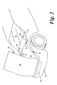
- Fig.2 is a perspective view of the front end of the vehicle shown in Fig.1, with the bonnet in an open position;
- Fig.3 is a view similar to Fig.1 to larger scale showing part of the bonnet and the lift actuator in a deployed position and the latch assembly in an open or release position;
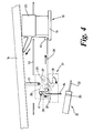
- Fig.4 is a view similar to Fig.3 illustrating how the latch assembly is re-set to its latch position,
- Fig.5 is a perspective view of the vehicle bonnet assembly from the outside of the vehicle showing the bonnet and lift actuator in a deployed position,
- Fig.6 is a perspective scrap view of the latch assembly to a larger scale, and
- Fig.7 is an exploded perspective scrap view of the circled part A in Fig.3 to larger scale.
- With reference to the drawings and in particular Figs. 1 and 2, there is shown a front end portion of a
vehicle body 10 having awindscreen 11, anengine compartment 12 and afront bumper 15. Theengine compartment 12 has anopening 13 covered by afront bonnet 14. Thebonnet 14 is fixed to thevehicle body 10 byhinges 16 at its front end and by two spaced apartlatch assemblies 17 located at the rear of thebonnet 14, conveniently referred to as right and left latch assemblies. Right andleft lift actuators 18 are located between thevehicle body 10 and the rear edge of thebonnet 14. Thelift actuators 18 together with thelatch assemblies 16 and thebonnet 14 form part of a vehicle bonnet assembly. - Each
lift actuator 18 includes in this example inflatable elements having abase 19 fixed to thevehicle body 10, acylindrical sleeve 20 covering thebase 19 and defining a chamber and a gas generator (not shown) as described inGB 2373218 - Each
latch assembly 17 is engageable, in a known manner, with astriker 21 having the form of a substantially U-shaped loop attached to thebonnet 14 and having a bar extending parallel to thebonnet 14 that can be retained in thelatch assembly 17. Eachlatch assembly 17 and itscorresponding striker 21 together form a latch device. - As can best be seen in Fig.6, each
latch assembly 17 comprises ahousing 22 formed by twoplates 23 having co-operating formations. Eachplate slot 25 for receiving thestriker 21. Contained within thehousing 22 is a spring-loadedlatch claw 26 that co-operates with arelease member 27 in a conventional manner. Thelatch claw 26 is pivotally mounted on a firsttransverse pivot pin 28 located on one side of theslots 25 and therelease member 27 is pivotally mounted on asecond pivot pin 29 located on the other side of theslots 25. A biasingspring 30 is coaxially mounted on eachtransverse pin release member 27 includes a ratchet to lock thelatch claw 26 in a latch position (Fig.4) and a projection lever orlatch pawl 31 which can be displaced by arelease actuator 32. In this example therelease actuator 32 is a pyrotechnic device which includes acylindrical piston 33 and acylindrical actuator body 34 within which is located a pyrotechnical charge. Thelatch pawl 31 in a know manner is also connected by a cable (not shown) to a lever (not shown) located inside the vehicle so as to release thelatch claw 26 from thestriker 21 thus allowing thebonnet 14 to be opened. - As can best be seen in Fig. 7, the
cylindrical body 34 has anannular groove 35 and is secured to thevehicle body 10 by an attachment in the form of abracket 36 fixed to thevehicle body 10 and having aslot 36a which is conformed to slidably receive theannular groove 35. The attachment also comprises aretention clip 37 which engages theannular groove 35 to secure thecylindrical body 34 to thebracket 36. In this example theretention clip 37 is a spring loaded clip having a substantially U-shaped form and which is inserted into thegroove 35 next to thebracket 36. Theclip 37 is attached in its upper part to anend 39 of an auxiliary release means in the form of arelease tape 38 which runs along a portion of the vehicle body through a set ofpulleys 41 fixed to thevehicle body 10 to be attached at itsother end 40 to thecylindrical sleeve 20 of thelift actuator 18. Therelease tape 38 is hidden from sight in a normal operation of thebonnet 14 under acover 42 fixed to thevehicle body 10 so as to prevent accidental release of thepyrotechnic device 32. - The vehicle bonnet assembly also comprises
impact sensors 43 secured to thefront bumper 15 and connected to acontrol unit 44. Thecontrol unit 44 is also connected to the gas generators of eachlift actuator 18 and to therelease actuators 31 of eachlatch assembly 17. - Operation of the bonnet assembly will now be described.
- As seen in Fig.1, the
bonnet 14 is in its normal position, i.e. covering theengine compartment 12, and is retained by the twolatch assemblies 17 in which eachstriker 21 is held by respective the latch claw 26 (Fig.1). To open thebonnet 14 the driver pulls the lever located inside the vehicle, moving therelease members 27 from thelatch claws 26 of eachlatch assembly 17. Eachlatch claw 26 moves towards its release position under the force of its spring to a position where thestrikers 21 can leave thehousing 22 of each latch assembly 17 (Fig.2). - When the
bonnet 14 is pivoted back to its normal position thestrikers 21 move thelatch claws 26 back into the latch position and are locked by the ratchets of therelease members 27 in a know manner. - In the event that the
impact sensors 43 recognize that the vehicle has hit a pedestrian, theimpact sensors 43 send a signal to thecontrol unit 44 which controls the pyrotechnic charges of the right andleft release actuators 32 and at the same time the gas generators of the right andleft lift actuators 18. - Each
release actuator 32 then moves therelease member 27 enabling the spring-loadedlatch claw 26 to take its release position, allowing thebonnet 14 to be displaced as thestrikers 21 are no longer held by thelatch claws 26. It will be appreciated that therelease actuators 32 is configured to jam therelease member 27 to retain it in the release position of thelatch claw 26 to ensure that thebonnet 14 will be raised correctly. Meanwhile the gas generators of thelift actuators 18 are ignited moving the respectivecylindrical sleeve 20 upwards and raising the rear of the bonnet 14 (Fig.3) forming thus a cushion device in order to help avoid pedestrians being injured by hard objects under thebonnet 14. It will be appreciated that if thebonnet 14 is raised following ignition of the gas generators and operations of therelease actuators 32 in response to an impact as mentioned above, thebonnet 14, if undamaged or not badly damaged cannot be re-latched on the latch device. This is because eachrelease actuator 32 prevents thecorresponding release member 27 from being moved back under the force of its spring and hence its associatedlatch claw 26 cannot move back to the latch position to allow the bonnet to be latched. To overcome this issue, theclip 37 and therelease tape 38 act as a release fastening device to allow therelease actuator 32 to be moved away from therelease member 27. - As a result of the frontal impact, the end of the
release tape 38 of eachlatch assembly 17 which is attached to thelift actuator 18 has been pulled upwards by the associatedlift actuators 18 and can now be grasped by an operator or the driver. The driver or operator pulls eachrelease tape 38 in order to decouple thespring clip 37 from theannular groove 35, releasing thebody 34 of therelease actuator 32 from theslot 36a of thebracket 36 and allowing therelease member 27 to move back to its position where it locks the latch claws in the latch position. Then thebonnet 14 can be pushed down to its normal position where thestrikers 21 will be held by thelatch claws 26 and thelift actuator 18 be retracted. It will be appreciated that the length of therelease tape 38 is sufficient to leave a small amount of slack when thebonnet 14 is deployed so that thelift actuator 18 cannot release theretention clip 37 when it is raised. - The vehicle bonnet assembly described here allows the
latch assemblies 17 to be re-set in the event of minor damage to thebonnet 14 after impact so that the vehicle can be driven to a garage for replacement of therelease actuators 32 andlift actuators 18 by a straightforward manual operation. - Although the invention has been described by way of an example with reference to a specific embodiment of the invention various modifications may be made without departing from the invention. For example, the vehicle bonnet assembly could include only one latch assembly and one lift actuator. In addition, the cylindrical body of the piston could be pivotally mounted to the vehicle body and held in an active position by a locking key connected to the release tape.
Claims (11)
- A vehicle having a vehicle body and a vehicle bonnet assembly including a bonnet (14) hinged at its front to the vehicle body (10) and latched at its rear to the vehicle body by at least one latch device, the or each latch device comprising a latch assembly (17) mounted to one of the bonnet (14) and the vehicle body (10) and a striker (21) mounted to the other of the bonnet (14) and the vehicle body (10), impact sensors (43) configured to detect a front collision with a pedestrian and at least one lift actuator (18) arranged to raise the rear edge of the bonnet (14) in response to a pedestrian impact, the latch assembly (17) including a latch claw (26) and a release member (27), the latch claw (26) being moveable between a latch position in which the striker (21) is held by the latch claw (26) and a release position in which the striker (21) is releasable from the latch claw (26) and the release member (27) being operable by a driver of the vehicle to allow the latch claw (26) to be moved towards its release position and allow the bonnet (14) to be lifted, wherein a release actuator (32) is arranged to move the release member (27) to allow the latch claw (26) to be moved towards its release position and retain it in said position when the bonnet (14) is lifted by the or each lift actuator (18) upon a pedestrian impact.
- Vehicle as claimed in claim 1 wherein the release actuator (32) has an actuator body (34) which is fixed to the vehicle body (10) by a releasable fastening device (37, 38).
- Vehicle as claimed in claim 2 wherein the releasable fastening device includes an auxiliary release means (38) to allow the release actuator (32) to be moved away from the release member (27) so as to allow the latch claw (26) to be moved back to its latch position, the auxiliary release means (38) being arranged in such way that it can be operated manually by an operator only after the bonnet has being raised by the or each lift actuator (18).
- Vehicle as claimed in claim 3 in which the auxiliary release means (38) is connected to the lift actuator (18).
- Vehicle as claimed in any one of claims 2 to 4 in which the releasable fastening device includes a retention clip (37) adapted to be connected to the release actuator (32) and an attachment for releasably attaching the release actuator (32) to the vehicle body (10) by the retention clip (37).
- Vehicle as claimed in any one of claims 1 to 5 in which the auxiliary release means (38) includes a pull tape which is attached at one end to the retention clip (37) and at its other end to a raising part of the lift actuator (18).
- Vehicle as claimed in claim 6 in which the pull tape (38) is hidden by part of the vehicle body in a normal use of the bonnet (14).
- Vehicle as claimed in any one of claims 1 to 7 in which the release actuator (32) includes a cylindrical piston (33) and a cylindrical body (34) in which a pyrotechnic charge is located so as to move the cylindrical piston (33).
- Vehicle as claimed in claim 8 in which the cylindrical body (34) includes an annular groove (35) and the attachment comprises a bracket (36) attached to the vehicle body (10), the bracket (36) being provided with a slot (36a) conformed to slidably receive the annular groove (35) of the cylindrical body (34) which is secured to the bracket (36) by insertion of the retention clip (37) into the groove (35).
- Vehicle as claimed in any one of claims 1 to 9 in which the latch claw (26) of the or each latch assembly is spring-loaded towards its release position and the release member (27) of the or each latch assembly is spring-loaded into the latch position and arranged to lock the latch claw (26), the release member (27) including a latch pawl (31) which is adapted to co-operate with the release actuator (32).
- Vehicle as claimed in any one of claims 1 to 10, in which the vehicle bonnet assembly comprises right and left latch devices and right and left lift actuators.
Applications Claiming Priority (1)
| Application Number | Priority Date | Filing Date | Title |
|---|---|---|---|
| GB0515876A GB2428644B (en) | 2005-08-02 | 2005-08-02 | A motor vehicle |
Publications (3)
| Publication Number | Publication Date |
|---|---|
| EP1749711A2 true EP1749711A2 (en) | 2007-02-07 |
| EP1749711A3 EP1749711A3 (en) | 2008-11-05 |
| EP1749711B1 EP1749711B1 (en) | 2010-10-27 |
Family
ID=34983940
Family Applications (1)
| Application Number | Title | Priority Date | Filing Date |
|---|---|---|---|
| EP20060270065 Active EP1749711B1 (en) | 2005-08-02 | 2006-07-06 | A motor vehicle with a front bonnet for pedestrian protection |
Country Status (6)
| Country | Link |
|---|---|
| US (1) | US7559399B2 (en) |
| EP (1) | EP1749711B1 (en) |
| JP (1) | JP5118828B2 (en) |
| AT (1) | ATE485977T1 (en) |
| DE (1) | DE602006017776D1 (en) |
| GB (1) | GB2428644B (en) |
Cited By (3)
| Publication number | Priority date | Publication date | Assignee | Title |
|---|---|---|---|---|
| DE102007021840A1 (en) * | 2007-05-07 | 2008-11-13 | BÖCO Böddecker & Co. GmbH & Co. KG | Aligning device for vehicle door has locking latch disconnected from released actuator element |
| FR2929210A3 (en) | 2008-03-31 | 2009-10-02 | Renault Sas | Bonnet structure for car, has pedestrian impact absorbing device with semi-rigid membrane formed of channels, which are connected to deformable pouches and variably co-operate with hinge based on speed of impact and deformation of bonnet |
| WO2016034725A1 (en) * | 2014-09-05 | 2016-03-10 | Jaguar Land Rover Limited | Bonnet displacement mechanism |
Families Citing this family (24)
| Publication number | Priority date | Publication date | Assignee | Title |
|---|---|---|---|---|
| DE102005044079A1 (en) * | 2005-09-15 | 2007-03-22 | GM Global Technology Operations, Inc., Detroit | Body for a motor vehicle |
| US7845691B2 (en) * | 2006-04-05 | 2010-12-07 | Ford Global Technologies, Llc | Collision safety system for use with a motor vehicle |
| DE102007034556A1 (en) * | 2007-07-25 | 2009-01-29 | Audi Ag | Locking device for the front flap of a motor vehicle |
| KR100851721B1 (en) | 2007-11-13 | 2008-08-11 | 현대자동차주식회사 | Vehicle hood latch separator |
| EP2489649A4 (en) | 2009-10-15 | 2014-01-01 | Nippon Kayaku Kk | Gas generating agent composition, molded product of the composition, and gas generation device equipped with the molded product |
| KR101154299B1 (en) * | 2010-09-28 | 2012-06-13 | 현대자동차주식회사 | Active hood latch system for vehicle |
| US8579068B2 (en) * | 2011-06-02 | 2013-11-12 | Ford Global Technologies, Llc | Hood latch and striker system for pedestrian protection |
| US8490735B2 (en) * | 2011-06-28 | 2013-07-23 | Ford Global Technologies | Vehicle hood structure for pedestrian body impact protection |
| KR101261921B1 (en) * | 2011-07-18 | 2013-05-08 | 현대자동차주식회사 | Active hood system for vehicle |
| JP2015505764A (en) * | 2011-12-06 | 2015-02-26 | マグナ クロージャーズ インコーポレイテッド | Components for active pedestrian safety mechanisms |
| US9145716B2 (en) * | 2012-05-09 | 2015-09-29 | Ford Global Technologies, Llc | Deployable hood latch for pedestrian head protection |
| KR101372022B1 (en) * | 2012-08-24 | 2014-03-07 | 기아자동차주식회사 | 2 step open hood latch apparatus for vehicle |
| CN105378200B (en) * | 2013-07-17 | 2018-05-15 | 麦格纳覆盖件有限公司 | The double motor device with bolt lock mechanism is drawn applied to dynamical system |
| KR101491298B1 (en) * | 2013-08-20 | 2015-02-06 | 현대자동차주식회사 | Active hood latch device for vehicle |
| US9033092B1 (en) * | 2013-11-21 | 2015-05-19 | Ford Global Technologies, Llc | Vehicle front end structure providing pedestrian protection |
| JP2017520734A (en) * | 2014-07-03 | 2017-07-27 | ティーケー ホールディングス インク.Tk Holdings Inc. | Actuator housing seal mechanism |
| EP3020895B1 (en) * | 2014-11-13 | 2017-11-15 | Huf Hülsbeck & Fürst GmbH & Co. KG | Handle for a vehicle with a pulling device |
| US10941592B2 (en) * | 2015-05-21 | 2021-03-09 | Magna Closures Inc. | Latch with double actuation and method of construction thereof |
| DE102015116669A1 (en) * | 2015-10-01 | 2017-04-06 | Kiekert Ag | Safety device with manually unlockable front hood |
| DE102019101992A1 (en) * | 2018-01-29 | 2019-08-01 | Magna Closures Inc. | Actuated active pedestrian safety interlock mechanism |
| JP7064457B2 (en) * | 2019-02-19 | 2022-05-10 | 本田技研工業株式会社 | Vehicle pop-up hood device |
| US12078003B2 (en) * | 2021-09-29 | 2024-09-03 | Honda Motor Co., Ltd. | Active front structure for vehicle |
| DE102022116438A1 (en) * | 2022-07-01 | 2024-01-04 | Bayerische Motoren Werke Aktiengesellschaft | Front lid hinge for a motor vehicle and motor vehicle with such a front lid hinge |
| JP2026066643A (en) * | 2024-10-07 | 2026-04-17 | 豊田合成株式会社 | Pop-up hood device |
Citations (1)
| Publication number | Priority date | Publication date | Assignee | Title |
|---|---|---|---|---|
| GB2382548A (en) | 2001-10-06 | 2003-06-04 | Ford Global Tech Inc | Release mechanism for vehicle bonnet |
Family Cites Families (14)
| Publication number | Priority date | Publication date | Assignee | Title |
|---|---|---|---|---|
| JP3744242B2 (en) * | 1999-01-26 | 2006-02-08 | マツダ株式会社 | Vehicle front structure |
| US6293362B1 (en) * | 1999-07-09 | 2001-09-25 | Honda Giken Kogyo Kabushiki Kaisha | Vehicle hood apparatus |
| JP3320681B2 (en) * | 1999-07-19 | 2002-09-03 | 本田技研工業株式会社 | Vehicle hood device |
| US6554093B2 (en) * | 2000-07-19 | 2003-04-29 | Honda Giken Kogyo Kabushiki Kaisha | Vehicular hood device |
| US6520276B2 (en) * | 2000-07-19 | 2003-02-18 | Honda Giken Kogyo Kabushiki Kaisha | Vehicle hood apparatus |
| US6513617B2 (en) * | 2000-07-26 | 2003-02-04 | Honda Giken Kogyo Kabushiki Kaisha | Vehicle hood apparatus |
| DE10056250A1 (en) * | 2000-11-14 | 2002-05-16 | Bayerische Motoren Werke Ag | Motor vehicle with a front hood |
| GB2387577A (en) * | 2002-04-17 | 2003-10-22 | Autoliv Dev | Impact responsive means for raising a vehicle bonnet |
| DE10259114B4 (en) * | 2002-12-18 | 2016-12-29 | Volkswagen Ag | Locking device for a front hood of a motor vehicle |
| DE10343106B4 (en) * | 2003-04-04 | 2015-08-20 | Witte-Velbert Gmbh & Co. Kg | Pyrotechnic triggering actuator |
| DE10350534B3 (en) * | 2003-10-29 | 2005-09-08 | Ise Innomotive Systems Europe Gmbh | Device for protecting people in a frontal collision with a motor vehicle by placing its front hood at least in the front hood lock area |
| FR2864936B1 (en) * | 2004-01-14 | 2008-08-15 | Pyroalliance | ACTUATOR HOOD LIFT WITH HOOK LATCH SYSTEM. |
| US7303040B2 (en) * | 2004-05-18 | 2007-12-04 | Autolive Asp, Inc. | Active vehicle hood system and method |
| US7195090B2 (en) * | 2004-08-16 | 2007-03-27 | Autoliv Asp, Inc. | Vehicle hood latch release system for improved pedestrian protection |
-
2005
- 2005-08-02 GB GB0515876A patent/GB2428644B/en not_active Expired - Lifetime
-
2006
- 2006-07-06 EP EP20060270065 patent/EP1749711B1/en active Active
- 2006-07-06 DE DE200660017776 patent/DE602006017776D1/en active Active
- 2006-07-06 AT AT06270065T patent/ATE485977T1/en not_active IP Right Cessation
- 2006-07-31 JP JP2006207802A patent/JP5118828B2/en not_active Expired - Fee Related
- 2006-08-01 US US11/461,562 patent/US7559399B2/en active Active
Patent Citations (1)
| Publication number | Priority date | Publication date | Assignee | Title |
|---|---|---|---|---|
| GB2382548A (en) | 2001-10-06 | 2003-06-04 | Ford Global Tech Inc | Release mechanism for vehicle bonnet |
Cited By (5)
| Publication number | Priority date | Publication date | Assignee | Title |
|---|---|---|---|---|
| DE102007021840A1 (en) * | 2007-05-07 | 2008-11-13 | BÖCO Böddecker & Co. GmbH & Co. KG | Aligning device for vehicle door has locking latch disconnected from released actuator element |
| DE102007021840B4 (en) * | 2007-05-07 | 2014-08-28 | BÖCO Böddecker & Co. GmbH & Co. KG | Device for installing a vehicle door |
| FR2929210A3 (en) | 2008-03-31 | 2009-10-02 | Renault Sas | Bonnet structure for car, has pedestrian impact absorbing device with semi-rigid membrane formed of channels, which are connected to deformable pouches and variably co-operate with hinge based on speed of impact and deformation of bonnet |
| WO2016034725A1 (en) * | 2014-09-05 | 2016-03-10 | Jaguar Land Rover Limited | Bonnet displacement mechanism |
| US10369959B2 (en) | 2014-09-05 | 2019-08-06 | Jaguar Land Rober Limited | Bonnet displacement mechanism |
Also Published As
| Publication number | Publication date |
|---|---|
| GB2428644A (en) | 2007-02-07 |
| US7559399B2 (en) | 2009-07-14 |
| JP2007039027A (en) | 2007-02-15 |
| EP1749711B1 (en) | 2010-10-27 |
| GB0515876D0 (en) | 2005-09-07 |
| ATE485977T1 (en) | 2010-11-15 |
| GB2428644B (en) | 2009-04-29 |
| EP1749711A3 (en) | 2008-11-05 |
| JP5118828B2 (en) | 2013-01-16 |
| DE602006017776D1 (en) | 2010-12-09 |
| US20070200359A1 (en) | 2007-08-30 |
Similar Documents
| Publication | Publication Date | Title |
|---|---|---|
| EP1749711B1 (en) | A motor vehicle with a front bonnet for pedestrian protection | |
| CN110094119B (en) | Actuation mechanism for an active pedestrian safety latch | |
| EP1842748B1 (en) | Collision safety system for use with a motor vehicle | |
| CN109881999B (en) | Relative displacement mechanism for active pedestrian safety latch | |
| US11168498B2 (en) | Active pedestrian hood latch with dual function cam lever | |
| CN105228883B (en) | Mechanical Assist Mechanism for Active Pedestrian Safety Latch | |
| KR101491298B1 (en) | Active hood latch device for vehicle | |
| US6942056B2 (en) | Safety device for lifting a bonnet of a motor vehicle in the event of a collision | |
| EP2788230B1 (en) | Components for active pedestrian safety mechanism | |
| US11060327B2 (en) | Actuated mechanism for active pedestrian safety latch | |
| KR101293974B1 (en) | Active hood latch device for vehicle | |
| US20020011372A1 (en) | Vehicle hood apparatus | |
| KR101272519B1 (en) | Active hood system for vehicle | |
| CN110723099B (en) | Vehicle body structure | |
| JPH11263191A (en) | Automotive hood jumping device | |
| JP2002079906A (en) | Vehicle hood lock device | |
| CN113445834B (en) | Latch device for vehicle | |
| CN111472627B (en) | Actuation mechanism for an active pedestrian safety latch with meshing gears | |
| CN110748249B (en) | Engine bonnet latch hook and vehicle | |
| KR0174007B1 (en) | Pre-tensioning device for car seat belt | |
| CN113561928A (en) | Hood lifter |
Legal Events
| Date | Code | Title | Description |
|---|---|---|---|
| PUAI | Public reference made under article 153(3) epc to a published international application that has entered the european phase |
Free format text: ORIGINAL CODE: 0009012 |
|
| AK | Designated contracting states |
Kind code of ref document: A2 Designated state(s): AT BE BG CH CY CZ DE DK EE ES FI FR GB GR HU IE IS IT LI LT LU LV MC NL PL PT RO SE SI SK TR |
|
| AX | Request for extension of the european patent |
Extension state: AL BA HR MK YU |
|
| RAP1 | Party data changed (applicant data changed or rights of an application transferred) |
Owner name: JAGUAR CARS LIMITED |
|
| PUAL | Search report despatched |
Free format text: ORIGINAL CODE: 0009013 |
|
| AK | Designated contracting states |
Kind code of ref document: A3 Designated state(s): AT BE BG CH CY CZ DE DK EE ES FI FR GB GR HU IE IS IT LI LT LU LV MC NL PL PT RO SE SI SK TR |
|
| AX | Request for extension of the european patent |
Extension state: AL BA HR MK RS |
|
| 17P | Request for examination filed |
Effective date: 20090506 |
|
| AKX | Designation fees paid |
Designated state(s): DE FR |
|
| 17Q | First examination report despatched |
Effective date: 20090615 |
|
| D17P | Request for examination filed (deleted) | ||
| R17P | Request for examination filed (corrected) |
Effective date: 20090505 |
|
| RBV | Designated contracting states (corrected) |
Designated state(s): AT BE BG CH CY CZ DE DK EE ES FI FR GB GR HU IE IS IT LI LT LU LV MC NL PL PT RO SE SI SK TR |
|
| GRAP | Despatch of communication of intention to grant a patent |
Free format text: ORIGINAL CODE: EPIDOSNIGR1 |
|
| GRAS | Grant fee paid |
Free format text: ORIGINAL CODE: EPIDOSNIGR3 |
|
| GRAA | (expected) grant |
Free format text: ORIGINAL CODE: 0009210 |
|
| AK | Designated contracting states |
Kind code of ref document: B1 Designated state(s): AT BE BG CH CY CZ DE DK EE ES FI FR GB GR HU IE IS IT LI LT LU LV MC NL PL PT RO SE SI SK TR |
|
| REG | Reference to a national code |
Ref country code: GB Ref legal event code: FG4D |
|
| REG | Reference to a national code |
Ref country code: CH Ref legal event code: EP |
|
| REG | Reference to a national code |
Ref country code: IE Ref legal event code: FG4D |
|
| REF | Corresponds to: |
Ref document number: 602006017776 Country of ref document: DE Date of ref document: 20101209 Kind code of ref document: P |
|
| REG | Reference to a national code |
Ref country code: NL Ref legal event code: VDEP Effective date: 20101027 |
|
| LTIE | Lt: invalidation of european patent or patent extension |
Effective date: 20101027 |
|
| PG25 | Lapsed in a contracting state [announced via postgrant information from national office to epo] |
Ref country code: LT Free format text: LAPSE BECAUSE OF FAILURE TO SUBMIT A TRANSLATION OF THE DESCRIPTION OR TO PAY THE FEE WITHIN THE PRESCRIBED TIME-LIMIT Effective date: 20101027 |
|
| PG25 | Lapsed in a contracting state [announced via postgrant information from national office to epo] |
Ref country code: SI Free format text: LAPSE BECAUSE OF FAILURE TO SUBMIT A TRANSLATION OF THE DESCRIPTION OR TO PAY THE FEE WITHIN THE PRESCRIBED TIME-LIMIT Effective date: 20101027 Ref country code: BG Free format text: LAPSE BECAUSE OF FAILURE TO SUBMIT A TRANSLATION OF THE DESCRIPTION OR TO PAY THE FEE WITHIN THE PRESCRIBED TIME-LIMIT Effective date: 20110127 Ref country code: IS Free format text: LAPSE BECAUSE OF FAILURE TO SUBMIT A TRANSLATION OF THE DESCRIPTION OR TO PAY THE FEE WITHIN THE PRESCRIBED TIME-LIMIT Effective date: 20110227 Ref country code: PT Free format text: LAPSE BECAUSE OF FAILURE TO SUBMIT A TRANSLATION OF THE DESCRIPTION OR TO PAY THE FEE WITHIN THE PRESCRIBED TIME-LIMIT Effective date: 20110228 Ref country code: AT Free format text: LAPSE BECAUSE OF FAILURE TO SUBMIT A TRANSLATION OF THE DESCRIPTION OR TO PAY THE FEE WITHIN THE PRESCRIBED TIME-LIMIT Effective date: 20101027 Ref country code: NL Free format text: LAPSE BECAUSE OF FAILURE TO SUBMIT A TRANSLATION OF THE DESCRIPTION OR TO PAY THE FEE WITHIN THE PRESCRIBED TIME-LIMIT Effective date: 20101027 Ref country code: LV Free format text: LAPSE BECAUSE OF FAILURE TO SUBMIT A TRANSLATION OF THE DESCRIPTION OR TO PAY THE FEE WITHIN THE PRESCRIBED TIME-LIMIT Effective date: 20101027 Ref country code: FI Free format text: LAPSE BECAUSE OF FAILURE TO SUBMIT A TRANSLATION OF THE DESCRIPTION OR TO PAY THE FEE WITHIN THE PRESCRIBED TIME-LIMIT Effective date: 20101027 Ref country code: SE Free format text: LAPSE BECAUSE OF FAILURE TO SUBMIT A TRANSLATION OF THE DESCRIPTION OR TO PAY THE FEE WITHIN THE PRESCRIBED TIME-LIMIT Effective date: 20101027 |
|
| PG25 | Lapsed in a contracting state [announced via postgrant information from national office to epo] |
Ref country code: GR Free format text: LAPSE BECAUSE OF FAILURE TO SUBMIT A TRANSLATION OF THE DESCRIPTION OR TO PAY THE FEE WITHIN THE PRESCRIBED TIME-LIMIT Effective date: 20110128 Ref country code: BE Free format text: LAPSE BECAUSE OF FAILURE TO SUBMIT A TRANSLATION OF THE DESCRIPTION OR TO PAY THE FEE WITHIN THE PRESCRIBED TIME-LIMIT Effective date: 20101027 |
|
| PG25 | Lapsed in a contracting state [announced via postgrant information from national office to epo] |
Ref country code: ES Free format text: LAPSE BECAUSE OF FAILURE TO SUBMIT A TRANSLATION OF THE DESCRIPTION OR TO PAY THE FEE WITHIN THE PRESCRIBED TIME-LIMIT Effective date: 20110207 Ref country code: CZ Free format text: LAPSE BECAUSE OF FAILURE TO SUBMIT A TRANSLATION OF THE DESCRIPTION OR TO PAY THE FEE WITHIN THE PRESCRIBED TIME-LIMIT Effective date: 20101027 Ref country code: EE Free format text: LAPSE BECAUSE OF FAILURE TO SUBMIT A TRANSLATION OF THE DESCRIPTION OR TO PAY THE FEE WITHIN THE PRESCRIBED TIME-LIMIT Effective date: 20101027 |
|
| PG25 | Lapsed in a contracting state [announced via postgrant information from national office to epo] |
Ref country code: PL Free format text: LAPSE BECAUSE OF FAILURE TO SUBMIT A TRANSLATION OF THE DESCRIPTION OR TO PAY THE FEE WITHIN THE PRESCRIBED TIME-LIMIT Effective date: 20101027 Ref country code: DK Free format text: LAPSE BECAUSE OF FAILURE TO SUBMIT A TRANSLATION OF THE DESCRIPTION OR TO PAY THE FEE WITHIN THE PRESCRIBED TIME-LIMIT Effective date: 20101027 Ref country code: RO Free format text: LAPSE BECAUSE OF FAILURE TO SUBMIT A TRANSLATION OF THE DESCRIPTION OR TO PAY THE FEE WITHIN THE PRESCRIBED TIME-LIMIT Effective date: 20101027 Ref country code: SK Free format text: LAPSE BECAUSE OF FAILURE TO SUBMIT A TRANSLATION OF THE DESCRIPTION OR TO PAY THE FEE WITHIN THE PRESCRIBED TIME-LIMIT Effective date: 20101027 |
|
| PLBE | No opposition filed within time limit |
Free format text: ORIGINAL CODE: 0009261 |
|
| STAA | Information on the status of an ep patent application or granted ep patent |
Free format text: STATUS: NO OPPOSITION FILED WITHIN TIME LIMIT |
|
| 26N | No opposition filed |
Effective date: 20110728 |
|
| REG | Reference to a national code |
Ref country code: DE Ref legal event code: R097 Ref document number: 602006017776 Country of ref document: DE Effective date: 20110728 |
|
| PG25 | Lapsed in a contracting state [announced via postgrant information from national office to epo] |
Ref country code: IT Free format text: LAPSE BECAUSE OF FAILURE TO SUBMIT A TRANSLATION OF THE DESCRIPTION OR TO PAY THE FEE WITHIN THE PRESCRIBED TIME-LIMIT Effective date: 20101027 |
|
| PG25 | Lapsed in a contracting state [announced via postgrant information from national office to epo] |
Ref country code: MC Free format text: LAPSE BECAUSE OF NON-PAYMENT OF DUE FEES Effective date: 20110731 |
|
| REG | Reference to a national code |
Ref country code: CH Ref legal event code: PL |
|
| REG | Reference to a national code |
Ref country code: IE Ref legal event code: MM4A |
|
| PG25 | Lapsed in a contracting state [announced via postgrant information from national office to epo] |
Ref country code: CH Free format text: LAPSE BECAUSE OF NON-PAYMENT OF DUE FEES Effective date: 20110731 Ref country code: LI Free format text: LAPSE BECAUSE OF NON-PAYMENT OF DUE FEES Effective date: 20110731 |
|
| PG25 | Lapsed in a contracting state [announced via postgrant information from national office to epo] |
Ref country code: IE Free format text: LAPSE BECAUSE OF NON-PAYMENT OF DUE FEES Effective date: 20110706 |
|
| PG25 | Lapsed in a contracting state [announced via postgrant information from national office to epo] |
Ref country code: LU Free format text: LAPSE BECAUSE OF NON-PAYMENT OF DUE FEES Effective date: 20110706 Ref country code: CY Free format text: LAPSE BECAUSE OF EXPIRATION OF PROTECTION Effective date: 20101027 |
|
| PG25 | Lapsed in a contracting state [announced via postgrant information from national office to epo] |
Ref country code: TR Free format text: LAPSE BECAUSE OF FAILURE TO SUBMIT A TRANSLATION OF THE DESCRIPTION OR TO PAY THE FEE WITHIN THE PRESCRIBED TIME-LIMIT Effective date: 20101027 |
|
| PG25 | Lapsed in a contracting state [announced via postgrant information from national office to epo] |
Ref country code: HU Free format text: LAPSE BECAUSE OF FAILURE TO SUBMIT A TRANSLATION OF THE DESCRIPTION OR TO PAY THE FEE WITHIN THE PRESCRIBED TIME-LIMIT Effective date: 20101027 |
|
| REG | Reference to a national code |
Ref country code: FR Ref legal event code: PLFP Year of fee payment: 11 |
|
| REG | Reference to a national code |
Ref country code: FR Ref legal event code: PLFP Year of fee payment: 12 |
|
| REG | Reference to a national code |
Ref country code: FR Ref legal event code: PLFP Year of fee payment: 13 |
|
| PGFP | Annual fee paid to national office [announced via postgrant information from national office to epo] |
Ref country code: FR Payment date: 20200623 Year of fee payment: 15 |
|
| PG25 | Lapsed in a contracting state [announced via postgrant information from national office to epo] |
Ref country code: FR Free format text: LAPSE BECAUSE OF NON-PAYMENT OF DUE FEES Effective date: 20210731 |
|
| P01 | Opt-out of the competence of the unified patent court (upc) registered |
Effective date: 20230528 |
|
| PGFP | Annual fee paid to national office [announced via postgrant information from national office to epo] |
Ref country code: DE Payment date: 20250722 Year of fee payment: 20 |
|
| PGFP | Annual fee paid to national office [announced via postgrant information from national office to epo] |
Ref country code: GB Payment date: 20250722 Year of fee payment: 20 |