JP2017520734A - Actuator housing seal mechanism - Google Patents
Actuator housing seal mechanism Download PDFInfo
- Publication number
- JP2017520734A JP2017520734A JP2016575729A JP2016575729A JP2017520734A JP 2017520734 A JP2017520734 A JP 2017520734A JP 2016575729 A JP2016575729 A JP 2016575729A JP 2016575729 A JP2016575729 A JP 2016575729A JP 2017520734 A JP2017520734 A JP 2017520734A
- Authority
- JP
- Japan
- Prior art keywords
- housing
- actuator
- striker
- piston rod
- sealing means
- Prior art date
- Legal status (The legal status is an assumption and is not a legal conclusion. Google has not performed a legal analysis and makes no representation as to the accuracy of the status listed.)
- Pending
Links
- 230000007246 mechanism Effects 0.000 title description 11
- 238000007789 sealing Methods 0.000 claims abstract description 74
- 239000012530 fluid Substances 0.000 claims abstract description 23
- 230000004044 response Effects 0.000 claims abstract description 10
- 238000006243 chemical reaction Methods 0.000 claims abstract description 5
- 238000004891 communication Methods 0.000 claims description 13
- 239000000463 material Substances 0.000 claims description 10
- 230000003014 reinforcing effect Effects 0.000 claims description 8
- 238000003780 insertion Methods 0.000 claims description 2
- 230000037431 insertion Effects 0.000 claims description 2
- 238000000034 method Methods 0.000 description 15
- 230000006835 compression Effects 0.000 description 7
- 238000007906 compression Methods 0.000 description 7
- 238000003466 welding Methods 0.000 description 4
- 230000004913 activation Effects 0.000 description 3
- 230000004048 modification Effects 0.000 description 3
- 238000012986 modification Methods 0.000 description 3
- 230000008901 benefit Effects 0.000 description 2
- 239000000356 contaminant Substances 0.000 description 2
- 238000013461 design Methods 0.000 description 2
- 239000013013 elastic material Substances 0.000 description 2
- 239000007769 metal material Substances 0.000 description 2
- 239000004593 Epoxy Substances 0.000 description 1
- 239000000853 adhesive Substances 0.000 description 1
- 230000001070 adhesive effect Effects 0.000 description 1
- 230000008859 change Effects 0.000 description 1
- 239000003086 colorant Substances 0.000 description 1
- 150000001875 compounds Chemical class 0.000 description 1
- 238000011109 contamination Methods 0.000 description 1
- 238000002788 crimping Methods 0.000 description 1
- 238000001514 detection method Methods 0.000 description 1
- 238000009434 installation Methods 0.000 description 1
- 230000014759 maintenance of location Effects 0.000 description 1
- 230000013011 mating Effects 0.000 description 1
- 229920000642 polymer Polymers 0.000 description 1
- 230000008569 process Effects 0.000 description 1
- 238000012552 review Methods 0.000 description 1
- 239000007787 solid Substances 0.000 description 1
- 238000006467 substitution reaction Methods 0.000 description 1
Images
Classifications
-
- B—PERFORMING OPERATIONS; TRANSPORTING
- B60—VEHICLES IN GENERAL
- B60R—VEHICLES, VEHICLE FITTINGS, OR VEHICLE PARTS, NOT OTHERWISE PROVIDED FOR
- B60R21/00—Arrangements or fittings on vehicles for protecting or preventing injuries to occupants or pedestrians in case of accidents or other traffic risks
- B60R21/34—Protecting non-occupants of a vehicle, e.g. pedestrians
- B60R21/38—Protecting non-occupants of a vehicle, e.g. pedestrians using means for lifting bonnets
-
- F—MECHANICAL ENGINEERING; LIGHTING; HEATING; WEAPONS; BLASTING
- F15—FLUID-PRESSURE ACTUATORS; HYDRAULICS OR PNEUMATICS IN GENERAL
- F15B—SYSTEMS ACTING BY MEANS OF FLUIDS IN GENERAL; FLUID-PRESSURE ACTUATORS, e.g. SERVOMOTORS; DETAILS OF FLUID-PRESSURE SYSTEMS, NOT OTHERWISE PROVIDED FOR
- F15B15/00—Fluid-actuated devices for displacing a member from one position to another; Gearing associated therewith
- F15B15/19—Pyrotechnical actuators
-
- F—MECHANICAL ENGINEERING; LIGHTING; HEATING; WEAPONS; BLASTING
- F15—FLUID-PRESSURE ACTUATORS; HYDRAULICS OR PNEUMATICS IN GENERAL
- F15B—SYSTEMS ACTING BY MEANS OF FLUIDS IN GENERAL; FLUID-PRESSURE ACTUATORS, e.g. SERVOMOTORS; DETAILS OF FLUID-PRESSURE SYSTEMS, NOT OTHERWISE PROVIDED FOR
- F15B15/00—Fluid-actuated devices for displacing a member from one position to another; Gearing associated therewith
- F15B15/08—Characterised by the construction of the motor unit
- F15B15/14—Characterised by the construction of the motor unit of the straight-cylinder type
- F15B15/1423—Component parts; Constructional details
- F15B15/1457—Piston rods
- F15B15/1461—Piston rod sealings
Landscapes
- Engineering & Computer Science (AREA)
- Mechanical Engineering (AREA)
- Chemical & Material Sciences (AREA)
- Analytical Chemistry (AREA)
- Physics & Mathematics (AREA)
- Fluid Mechanics (AREA)
- General Engineering & Computer Science (AREA)
- Actuator (AREA)
- Lock And Its Accessories (AREA)
- Superstructure Of Vehicle (AREA)
Abstract
加圧流体を動力源とするアクチュエータ(10)は、ハウジング(12)とハウジング(12)に移動可能に連結されるストライカ(500)とを有する。弾性シール手段(650)は、ストライカ(500)とハウジング(12)との間に位置する。シール手段(650)は、ハウジング(12)に向く第1方向にストライカ(500)によりシール手段(650)に作用する力に応答して、ハウジングの一端をシールするように圧縮可能である。解放可能な保持手段(600,50z)は、ストライカ(500)に作動可能に連結され、かつ、アクチュエータ(10)の作動前に第1方向と反対の第2方向へのストライカ(500)の動きを防止するように構成され、シール手段(650)が圧縮されたときに、シール手段(650)によりストライカ(500)に作用する第2方向の反作用力に応答する。【選択図】図1The actuator (10) using a pressurized fluid as a power source includes a housing (12) and a striker (500) movably connected to the housing (12). The elastic sealing means (650) is located between the striker (500) and the housing (12). The sealing means (650) is compressible to seal one end of the housing in response to a force acting on the sealing means (650) by the striker (500) in a first direction toward the housing (12). The releasable holding means (600, 50z) is operably connected to the striker (500) and the movement of the striker (500) in a second direction opposite to the first direction prior to operation of the actuator (10). When the sealing means (650) is compressed, the sealing means (650) responds to the reaction force in the second direction acting on the striker (500). [Selection] Figure 1
Description
関連出願の相互参照
本願は、2014年7月3日付け米国仮出願、第62/020,973号の利益を有するものであり、参照することによりその全体が本願に含まれる。
This application has the benefit of US Provisional Application No. 62 / 020,973, Jul. 3, 2014, which is hereby incorporated by reference in its entirety.
ここに記載の実施形態は、全体的には加圧流体駆動アクチュエータに関し、特に、アクチュエータが作動する前にアクチュエータを周囲からシールするための方法及び/または機構に関する。 The embodiments described herein relate generally to pressurized fluid driven actuators and, more particularly, to methods and / or mechanisms for sealing an actuator from the environment before the actuator is actuated.
加圧流体を動力源とするピストン駆動のアクチュエータでは、加圧流体源(例えば火工ガス発生器)からの流体がピストンに加えられ、これにより、ハウジング内でピストンを移動し、取り付けられたピストンロッドがアクチュエータハウジングから展開または伸長される。この方法では、アクチュエータハウジングの外側に配置される駆動可能部材にピストンロッドで力を作用させても良い。 In piston-driven actuators powered by pressurized fluid, fluid from a pressurized fluid source (eg, pyrotechnic gas generator) is applied to the piston, thereby moving the piston within the housing and mounting the piston The rod is deployed or extended from the actuator housing. In this method, a force may be applied to the drivable member disposed outside the actuator housing with a piston rod.
特定のアクチュエータデザイン及び用途では、アクチュエータハウジングをシールし、アクチュエータの作動前に汚染物または異物が入るのを防止することが望ましい。このような汚染物及び異物は、アクチュエータの適正な作動を阻止または阻害する可能性がある。アクチュエータをシールする既知の技術は、特定の用途では構造的に不都合であり、例えば多数のシール関連部材を追加することにより、望ましくないまたは受け入れ難い追加コストを招くことがある。 In certain actuator designs and applications, it is desirable to seal the actuator housing to prevent contamination or foreign objects from entering prior to operation of the actuator. Such contaminants and foreign objects can prevent or inhibit proper operation of the actuator. Known techniques for sealing actuators are structurally inconvenient for certain applications and can result in undesirable or unacceptable additional costs, for example by adding a large number of seal-related members.
したがって、アクチュエータの作動前にアクチュエータハウジングをシールする改善された方法及び/または機構に対する必要性が存在している。 Thus, a need exists for an improved method and / or mechanism for sealing an actuator housing prior to actuation of the actuator.
ここに記載の実施形態の1つの態様では、加圧流体を動力源とするアクチュエータが提供される。アクチュエータは、ハウジングと、ハウジングに移動可能に連結されたストライカとを有する。弾性シール部材がストライカとハウジングとの間に配置される。シール手段は、ハウジングに向く第1方向に、ストライカがシール手段に作用させる力に応答してハウジングの端部をシールするように、圧縮可能である。解放可能な保持手段がストライカに作動可能に連結され、アクチュエータの作動前に、シール手段が圧縮されたときに、シール部材によりストライカに作用する第2方向の反作用力に応答して、第1方向と反対の第2方向におけるストライカの動きを防止するように構成される。 In one aspect of the embodiments described herein, an actuator powered by a pressurized fluid is provided. The actuator has a housing and a striker movably connected to the housing. An elastic seal member is disposed between the striker and the housing. The sealing means is compressible in a first direction toward the housing such that the end of the housing is sealed in response to the force exerted by the striker on the sealing means. A releasable retaining means is operably coupled to the striker and, in response to a reaction force in a second direction acting on the striker by the sealing member when the sealing means is compressed prior to actuation of the actuator, the first direction Is configured to prevent movement of the striker in a second direction opposite to.
ここに記載の実施形態の他の態様では、アクチュエータが提供される。アクチュエータは、ハウジングの外部と内部との間を流体連通可能な開口を有するアクチュエータハウジングを有する。ストライカがハウジングに移動可能に連結され、ハウジングの外部に位置する支承部を有する。支承面はストライカ支承部の反対側に位置する。支承面は、ハウジング内部と流体連通可能な開口を画定する。シール手段も設けられ、支承面開口に外接するように支承面と当接するように構成される。シール手段は、更に、ストライカと支承面との間にシールを形成するように、ストライカ支承部と支承面との間で圧縮可能に構成される。解放可能な保持手段は、ストライカに作動可能に連結される。保持手段は、アクチュエータの作動前に、シール手段が圧縮されたときに、ハウジングから離隔する方向にストライカが移動するのを防止するように構成される。 In other aspects of the embodiments described herein, an actuator is provided. The actuator has an actuator housing having an opening capable of fluid communication between the outside and the inside of the housing. A striker is movably connected to the housing and has a support portion located outside the housing. The bearing surface is located on the opposite side of the striker bearing. The bearing surface defines an opening in fluid communication with the interior of the housing. Sealing means is also provided and is configured to contact the bearing surface so as to circumscribe the bearing surface opening. The sealing means is further configured to be compressible between the striker bearing and the bearing surface so as to form a seal between the striker and the bearing surface. The releasable holding means is operably connected to the striker. The retaining means is configured to prevent the striker from moving in a direction away from the housing when the sealing means is compressed prior to actuation of the actuator.
ここに記載の実施形態の他の態様では、アクチュエータが提供される。アクチュエータは、ハウジングの外部と内部との間を流体連通可能な開口を有するアクチュエータハウジングを有する。ピストンロッドはハウジング内に移動可能に配置される。ストライカは、ピストンロッドと共に移動するために、ピストンロッドに作動可能に連結される。ストライカは、ハウジングの外部に位置する支承部を有する。支承面はストライカ支承部の反対側に位置する。支承面は、ハウジング内部と流体連通可能な開口を画定する。シール手段も設けられ、支承面開口に外接するように支承面と当接するように構成される。シール手段は、更に、ストライカと支承面との間にシールを形成するように、ストライカ支承部と支承面との間で圧縮可能に構成される。解放可能な保持手段は、ピストンロッドに作動可能に連結される。保持手段は、アクチュエータの作動前に、シール手段が圧縮されたときに、ハウジング内部からハウジング外部の方向へのピストンロッドの移動を阻止するように構成される。 In other aspects of the embodiments described herein, an actuator is provided. The actuator has an actuator housing having an opening capable of fluid communication between the outside and the inside of the housing. The piston rod is movably disposed in the housing. The striker is operably coupled to the piston rod for movement with the piston rod. The striker has a support portion located outside the housing. The bearing surface is located on the opposite side of the striker bearing. The bearing surface defines an opening in fluid communication with the interior of the housing. Sealing means is also provided and is configured to contact the bearing surface so as to circumscribe the bearing surface opening. The sealing means is further configured to be compressible between the striker bearing and the bearing surface so as to form a seal between the striker and the bearing surface. The releasable holding means is operably connected to the piston rod. The retaining means is configured to prevent movement of the piston rod from the interior of the housing to the exterior of the housing when the sealing means is compressed prior to actuation of the actuator.
同様な参照符号は、説明を通じて複数の図の同様な部材を示す。
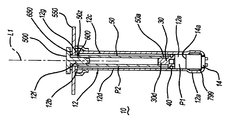
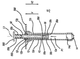
図1〜2は、作動直前(図1)及び作動後(図2)の加圧ガスを動力源とするアクチュエータの側部断面図を示す。アクチュエータ10は任意の適切な装置または機構に搭載しても良く、作動したときに装置または機構に力を伝達するために装置または機構に作動可能に連結(以下に詳細に説明するピストンロッド50を介して)しても良い。駆動力は、加圧流体(例えば、加圧ガス)がアクチュエータのハウジング内に、以下に説明する方法で導入されることに応答して生成される。加圧ガスは、ハウジング内で生成され(例えば、ハウジング内に組み込まれたガスジェネレータにより)、または、ガスは、ハウジング内部と流体連通する外部ガス源からハウジング内に導入しても良い。ここに記載のようにアクチュエータに対する1つの可能な用途は、自動車のフードの部分のリフトである。
Like reference numerals refer to like elements of the figures throughout the description.
1 and 2 are side sectional views of an actuator using a pressurized gas as a power source immediately before operation (FIG. 1) and after operation (FIG. 2).
ここに示す実施形態では、アクチュエータ10はハウジング12と、ハウジング内に摺動可能に位置するピストン30と、ピストンと共に移動するためにピストンに取り付けられたピストンロッド50とを有する。ハウジング12は、第1端部12aを画定する最外側ハウジング壁12dと、第2端部12bと、ハウジング12の長手方向中央軸L1と、第1端部と第2端部とを接続するボディ12cとを有する。壁12dは、更に、ハウジングの中空内部12eを画定する。図1〜2に示す実施形態では、ハウジング第1端部12aは半径方向外方に広がり、内部に挿入され、クリンピング、接着取付けまたは任意の他の適切な方法で保持される適切なガスジェネレータ14(例えば、既知のマイクロガスジェネレータ)を収容する。これに代え、ガスジェネレータ14は、適切な保持方法を使用してハウジング第1端部の外側に取り付けても良い。ガスジェネレータ14のガス放出部14aがハウジング内に位置し、したがって、発生したガスはガスジェネレータを作動した後にハウジング内部に流入する。必要な場合は、適切なシール(エポキシシール、Oリングシール、または、他のシール手段)(図示しない)を設け、ガスジェネレータ14とハウジング12との間から、発生したガスがハウジングの外部に漏洩するのを防止しまたは最小としても良い。
In the illustrated embodiment, the
図1〜2に示す実施形態では、第2端部12bはピストン30に取り付けられたピストンロッド50の一部を、それを通して受け入れるように構成された開口12fを有し、これは、ハウジング内部に摺動可能に位置する。開口12fは、ロッドの部分が開口12fを通してハウジングに出入りするときに、ピストンロッド50を側方に拘束しまたは支えるように、大きさを形成しまたは構成しても良い。図1〜2に示す特定の実施形態では、端壁12gはハウジング12の一部から形成され、開口12fは、端壁12gに穿設され、または、形成される。
In the embodiment shown in FIGS. 1-2, the
支承面は、それに対するシール手段650(後述する)の圧縮を可能とするために設けられる。支承面は、ハウジングの外部と内部との間の流体連通を可能とする開口を画定する。図4〜5に示す実施形態では、シール手段は、溶接または他の任意の適切な手段でハウジング12に固定された装着部材550により、設けられる。装着部材550は、組み立てられたアクチュエータを、駆動力が伝達されるべき車両または他の機構に取り付けるために使用しても良い。図に示す実施形態では、装着部材550は、それに形成されたボルト孔550aを有する平坦なプレートで形成される。しかし、装着部材は、特定の用途の必要に対して適合可能な任意の構成を有しても良い。装着部材550は、ハウジングと装着部材との間にガス密のシールを形成するように、ハウジング端部12bに取り付けても良い。装着部材550が図4〜5に示すように、その間にガス密のシール形成するようにハウジング12に取り付けられるときに、開口550pは、それを介してハウジングの外部とハウジングの内部との間の流体連通を可能とする。
The bearing surface is provided to allow compression of sealing means 650 (described below) against it. The bearing surface defines an opening that allows fluid communication between the exterior and interior of the housing. In the embodiment shown in FIGS. 4-5, the sealing means is provided by a mounting
図1〜5に示す実施形態では、装着部材550はカラー560を使用してハウジング12に固定される。図示の実施形態では、カラー560は、第1の比較的大径の部分560aと、第1の部分560aから延びる第2の比較的小径の部分560bとを有する。装着部材550は第1の部分560aの端面560cに当接し、溶接または他の適切な手段を使用して、この位置でカラーに固定される。第2の部分560bは、ハウジング壁12dの外面と密に嵌合しまたはわずかに締まり嵌めを形成し、装着部材がハウジング端部12bに当接するまでハウジング壁に沿って摺動しても良い。そして、装着部材550は、カラー端部560dとハウジング12との間の界面に沿って、溶接または適切にカラーをハウジングに固定することにより、この位置に固定しても良い。
In the embodiment shown in FIGS. 1-5, the mounting
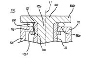
図5Aを参照すると、アクチュエータの他の実施形態110では、シール手段の支承面は、ハウジング端部12bで形成され、これは、ストライカ500が図示のようにハウジングの端壁12gに対してシール手段650を圧縮することができるように構成され、これにより、装着部材550をハウジングの外部の他の部分に対して省略しまたは再配置することを可能とする。この実施形態では、開口12fはそれを介してハウジングの外部とハウジングの内部との間の流体連通を可能とする。
Referring to FIG. 5A, in another
ピストン30は、ハウジング内部12e内に摺動可能に配置される。ピストンは、外壁30bを設けたベース30aを有する。溝30cが壁部30bに形成され、Oリング40または他の適切な弾性ガス密シールを内部に受け入れるように構成される。既知の方法で、Oリング40は弾力的に摺動してハウジング壁12dの内面に接触し、これにより、実質的にガス密のシールをピストン30と壁部12dとの間に形成する。ピストン30が、Oリング40をハウジング壁の内面に接触させた状態でハウジング12内に配置されると、Oリングとハウジング壁との間の接触領域は、ピストンの高圧側P1とピストンの低圧側P2との間の境界を画定する。
The
図1〜2に示す実施形態では、突起30dがベース30aから延びる。突起30dは、締まり嵌めされて関連するピストンロッド50に係合する(または、適切に取り付けられる)ように、または、ピストン30に対してピストンロッド50の取り付けを可能若しくは容易とするように、構成される。
1-2, the
ピストンロッド50は、駆動力をピストンロッドに接続される部材(例えば、車両のフードの部分(図9に部材902等で概略的に示す))に伝達する機構である。ピストンロッド50は、ピストンと共に移動するように、ピストンに取り付けられる第1端部50aを有する。第1端部と対向する第2端部50bは、駆動力が伝達されるべき任意の部材または機構に取り付けられ(または、支え)るように構成しても良い。図1〜2に示す実施形態では、ピストンロッド50は中空である。または、ピストンロッドは中実であっても良い。ピストンロッドは、更に、特定の用途に対して適合しまたは必要な任意の特定長さ、径、形状、及び/または、他の特性(複数可)を有しても良い。
The
更に、図3に示すように、解放可能な保持手段(本明細書中、他の部分で説明する)の一部として、溝または肩部50zを、ピストンロッドの第2端部50bに近接するピストンロッド50の外面に沿って形成しても良い。溝50zは、後述するように、保持クリップ600の部分をその内部に受け入れる大きさに形成されている。
Further, as shown in FIG. 3, as part of the releasable retaining means (discussed elsewhere herein), a groove or
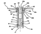
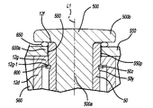
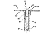
図3〜5は、アクチュエータ10の組み立て中における種々の段階における図1〜2のハウジング12の第2端部12bを示す拡大断面図である。図3は、ハウジングのシール手段650(後述する)の圧縮前のアクチュエータを示す。図4は、シール手段650の圧縮中のアクチュエータの1つの実施形態に作用する力を示す。図5は、ストライカ500(後述する)がピストンロッド50に完全に組み立てられた後のアクチュエータを、圧縮された状態のシール手段650と共に示す。
3-5 are enlarged cross-sectional views illustrating the
ここに記載の実施形態では、ストライカ500は、ピストンロッドの第2端部50bに取り付けることにより、ハウジングに移動可能に連結される。ストライカ500は、対象物の表面に直接接触し、アクチュエータが作動した後に、対象物に駆動力を伝達するように構成される。ストライカ500は、更に、ストライカがピストンロッドに取り付けられまたは連結されたときに、シール手段650(後述する)に圧力を作用させ、これにより、ここに記載のようにガス密なハウジングシールを形成する。図示の実施形態では、ストライカ500はベース部500aと、ベース部から外方に延びる支承部500bを有する。支承部500bは、ストライカがピストンロッドに組み立てられたときに、シール650を圧縮する。ストライカ500は、例えば金属材料、ポリマーまたは他の材料である任意の適切な材料で形成しても良い。
In the described embodiment, the
ストライカ500は、任意の適切な方法を使用してピストンロッド50に取り付けても良い。1つの実施形態では、ねじ(図示しない)がストライカのベース部の外面に沿って形成され、相補的に、相手方のねじ(図示しない)が中空ピストンロッドの壁の内面に沿って形成される。他の実施形態では、ストライカのベース部500aは、ベース部がピストンロッド内に挿入されたときに、ピストンロッド壁に締まり嵌め嵌合して係合する。他の方法は、ストライカをピストンロッドに固定するために使用しても良い。ストライカをピストンロッドに組み立てる間、ストライカはシール手段650に圧力を作用させ、支承面(これは、図1〜5に示す実施形態では、装着部材550で形成される)に対してシール650を圧縮し、これにより、後述するようにハウジングシールを形成する。ストライカをピストンロッドに固定するための任意の方法は、アクチュエータの組み立て後の全期間に対してシール手段650の圧縮を維持するために、アクチュエータの装着中(例えば、車両のフードリフタに用いる場合)及びアクチュエータの作動前に、ピストンロッド50に対して所定位置にストライカを保持しなければならない。
The
シール手段650が装着部材550とストライカ500との間に位置する。いくつかの実施形態では、シール手段650は、装着部材とストライカとの間でシールが圧縮されたときに、弾性的に変形して装着部材550とストライカ500との間にガス密のシールを形成するように構成されかつ位置している。このシールは、アクチュエータの作動前にハウジング開口12fを通して周囲環境が汚染されるのを阻止する支援をなす。用語「弾性変形可能」及び「弾性変形」は、ここでは、作用した力に応答して変形し、作用する力が除去されたときにその非変形状態に戻るアクチュエータの部材を指す。このような部材は、アクチュエータに対して力を作用させる機能に対抗する反作用力も働く。
Sealing means 650 is located between the mounting
シール手段650は、更に、シール手段とシール手段に対する支承面との間の接触領域が支承面に形成された開口に外接するように、支承面に当接するように構成される。ここで使用される開口12fとの関係でシール手段の位置決めに適用される用語「外接(circumscribe)」は、「境界内に囲むこと」(すなわち、支承面に当接するシール手段の部分が、支承面開口を包囲しまたは取り囲み、したがって、シール手段が圧縮されたときに、ストライカと支承面との間に流体密なシールが形成される)を意味する。例えば、図4〜5に示すように、シール手段650と装着部材との間の環状接触領域650aは、装着部材に形成された開口550pを取り囲みまたは包囲する。図5Aに示すように、シール手段650とハウジング端壁12Gとの間の環状接触領域650aは、ハウジング第2端部12bに形成された開口12fを取り囲みまたは包囲する。
The sealing means 650 is further configured to abut the bearing surface such that a contact area between the sealing means and the bearing surface for the sealing means circumscribes an opening formed in the bearing surface. The term “circumscrib” applied to the positioning of the sealing means in relation to the
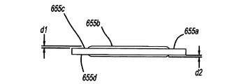
1つの特定の実施形態では、シール手段650は、ゴムまたは他の任意の適切な変形可能材料で形成されたOリングまたはガスケットであり、ピストンロッドの端部50b上に装着しても良い。図7及び8A〜8Cを参照すると、他の特定の実施形態655では、シール手段は、例えばゴム化合物等の弾性または他の弾性変形可能材料655bでオーバーモールドされたリングまたはワッシャ655aの形態である。図示の実施形態では、ワッシャ655aは、一対の対向する平行面655c及び655dを有する。オーバーモールドされた弾性材料655bは、それぞれ面655c及び655dを通って反対方向V及びV2に、面655cから距離d1及び面655dから距離d2に延びる。距離d1及びd2は、等しくてもまたは異なっても良い。図7を参照すると、ストライカが支承面に向けて方向V2に付勢されると、ワッシャ655aの両側にオーバーモールドされた弾性材料655bが、ワッシャに向く方向に圧縮される。
In one particular embodiment, the sealing means 650 is an O-ring or gasket formed of rubber or any other suitable deformable material and may be mounted on the
または、非弾性シール手段を、装着部材とストライカとの間で圧縮してシールを形成しても良い。または、種々の任意の他の弾性または非弾性シール手段を使用しても良い。支承面(例えば装着部材550またはハウジング端部12b)、ピストンロッド50、及び、ストライカ500の特定の構造的特徴は、用いるべきシール手段のタイプにしたがって画定しても良い。
Alternatively, the non-elastic sealing means may be compressed between the mounting member and the striker to form a seal. Alternatively, a variety of any other elastic or inelastic sealing means may be used. Specific structural features of the bearing surface (eg, mounting
上述の実施形態及び機構は、アクチュエータの作動前にアクチュエータハウジングの内部を環境的にシールするための効果的な方法を提供する。
図3〜5Aを参照すると、解放可能な保持手段の一部として、保持クリップ600がピストンロッド溝50z内に位置している。クリップ600は、例えば、クリップで画定された中央開口内へのピストンロッドの挿入に応じて弾力的に収縮可能または膨張可能に構成された従来のスナップリングの形成としても良い。クリップ600は、ハウジング内に位置する機能(feature)に当接し、アクチュエータの作動前、及び、方向Vでピストンロッド/ストライカサブアセンブリに圧縮されたシール手段により作用される力に応答して、ピストンロッド及びピストンロッドに連結されたストライカの双方のハウジング内部からハウジング外部の方向(すなわち矢印V(図2)の方向)への動きを防止または制限する。図示の実施形態では、クリップ600は、ハウジング内部でハウジング端壁12gの面12g−1当接するように構成され、シール手段が圧縮され、アクチュエータの作動前に、方向Vでピストンロッド50及びストライカ500の動きを防止する。
The embodiments and mechanisms described above provide an effective method for environmentally sealing the interior of the actuator housing prior to actuation of the actuator.
Referring to FIGS. 3-5A, as part of the releasable retaining means, a retaining
アクチュエータの組み立て中、方向Vでピストンロッド50に力が作用し、したがって、クリップ600がハウジング端壁12g(または、ハウジング内に配置される他の適切な機能)に当接する。ピストンロッドがこの位置に維持されている間、力がストライカ500に作用し、ストライカを方向V2に、更にピストンロッドの中空内部に付勢し、同時に、ストライカ支承部500bと支承面との間にシール手段650を圧縮する。この後、ストライカ500は、シール手段650がストライカと支承面との間で圧縮される位置に固定または保持される。シール手段は、この後圧縮されたままとなり、これにより、アクチュエータの作動前にハウジング12内への汚染物の侵入阻止を支援するガス密のシールを形成する。
During assembly of the actuator, a force is exerted on the
特定の実施形態では、ストライカは、ねじ接続によりピストンロッドに固定される。クリップ600がハウジング端壁12gに当接及び固定された状態で、ストライカが、ピストンロッドに対してそれを回転することによりピストンロッド内にねじ込むと、ストライカ支承部500bが支承面(図1〜5における装着部材550)に向けて引き出され、これによりシール手段650を圧縮する。シール手段650が圧縮された状態のときに、シール手段は、クリップ600で形成される保持力に抗して、ストライカ/ピストンロッドサブアセンブリを方向Vに押圧しようとする反作用力を作用させる。クリップ600及び溝50zは、シール手段の初期圧縮中及び更に続く、アクチュエータ装着(例えば、車両のフードリフタの用途で)を通してアクチュエータ組み立ての全期間中、及び、アクチュエータの作動前に、溝50z内にクリップ600が維持されるように、構成される。クリップ600及び溝50zは、更に、ピストン30に作用する加圧ガスで形成される力((例えばガスジェネレータ14の作動により)アクチュエータの作動から生じる)がクリップ600の変形及び/またはクリップ600の溝50zからの放出若しくは解放を生じるために十分であるように構成されることにより、クリップ保持力を克服し、これにより、クリップは、方向Vにおけるピストンロッドの動きに対する抵抗を作用させることはなく、または、クリップで作用する何らかの力は、ピストンロッドの動きに対する抵抗が極めて小さく、アクチュエータの所要の機能を阻害しない。これは、ピストンロッド及びストライカを解放し、方向Vにさらに移動する。所与の用途に対する所要の保持特性を提供するために必要なクリップ及び溝の詳細な構造(寸法を含めて)は、既知の手続きを使用して経験から分析的及び/または反復して決定しても良い。
In certain embodiments, the striker is secured to the piston rod by a screw connection. When the striker is screwed into the piston rod by rotating it relative to the piston rod while the
必要な場合は、ピストンロッド端部50aに最も近接する溝内またはその側部に沿って形成された溝50zは、傾斜面または傾斜路50y(例えば、図4及び5に示すように)を有しても良い。これは、アクチュエータが作動した後に、ピストンロッドが方向Vに移動したときに、溝50zからの保持クリップ600の除去を容易とする傾斜面を有する。傾斜面の寸法は、保持クリップを溝50zから押し出すために必要な力の大きさを適合させるように調節しても良い。
If necessary, the
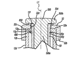
図6A〜6Bを参照すると、アクチュエータの他の代替的実施形態210では、シール手段を圧縮するために使用された支承面は、ハウジング端壁12gを、ピストンストロークの最後(すなわち、フルストロークで)に端壁に接触するピストン30で作用する衝撃力に対して補強または強化するために、ハウジング端部12bに適用される補強部材32で提供される。
Referring to FIGS. 6A-6B, in another
図6A〜6Bに示す実施形態では、補強部材32は、溶接または任意の他の適切な方法でハウジング12の端部に取り付けられるカラーまたはキャップの形態である。しかし、キャップは、特定の用途の必要に対して適切な任意の他の構成を有しても良い。図6A〜6Bに示す実施形態では、キャップ32は、ベース部32aと、ベース部の縁部から第1方向に延びる壁32bとを有し、その内部にハウジング第2端部12bの一部を受け入れるように構成される凹部32cを画定する。キャップベース部32aも、それに形成された開口32dを有する。開口32dは、ハウジング12内で開口12fと同軸(または、整合して)であり、開口を通ってピストンロッド50内に延びる。開口32dは、キャプ32がハウジング端部に取り付けられたときに、ハウジング12の内部と流体連通可能とする。この実施形態では、キャップベース部32aの外面32xは、シール手段650が、上述のようにストライカ500で作用する力で圧縮される支承面を提供する。開口32dは、ピストンロッド50と開口の縁部との間に間隙を形成する大きさに形成し、または、ピストンロッドをピストンロッドの移動中に開口の縁部に沿って摺動可能としても良い。補強部材32は、金属材料または他の任意の適切な材料または複数材料から形成しても良い。
In the embodiment shown in FIGS. 6A-6B, the reinforcing
更に、図6A〜6Bに示す実施形態は、ハウジング外部の中央位置に移動された装着部材550´及び関連する取付けカラー560´(図1〜5に示しかつ既に説明した装着部材550及びカラー560と同様)を有する。
In addition, the embodiment shown in FIGS. 6A-6B includes a mounting
図6A〜6Bを参照すると、アクチュエータに対するシール手段650を適用する1つの態様では、アクチュエータにシール部材650を装着しようとするときに、シール手段650は、キャップ開口32dを取り囲みまたは外接するように、補強部材支承面32xに適用される。これに代え、シール手段650は、ストライカ軸受部500bに載置されるように、ストライカベース部500aの上に適用しても良い。この後、ストライカベース部500aは、ピストンロッド第2端部50b内に挿入され、上述した方法でピストンロッド第1端部50aに向けて、キャップ支承面32xに対してシール手段650をストライカ軸受部500bが圧縮するまで、付勢し、これにより、ストライカ500と補強部材32との間にシールを形成する。ストライカは、この後、この圧縮位置に残りまたは固定される。
With reference to FIGS. 6A-6B, in one aspect of applying the sealing means 650 to the actuator, the sealing means 650 surrounds or circumscribes the
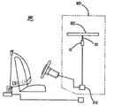
図9は、車両880に装着した歩行者保護システム900の一部の概略図であり、ここに記載の実施形態によるアクチュエータ10をフードリフト装置として組み込んである。この歩行者保護システム900の実施形態では、保護システムは、車両と歩行者との間の接触を検知または予測する(例えば、レーダまたはライダーセンサを使用して)ように構成された車両搭載センサ装置810を有する。センサ装置は、車両と歩行者(図示しない)との接触を検知または予測し、この接触の検知または予測に応じて、活性化信号をフードリフト機構10に送信し、この結果、ガスジェネレータが作動しまたは加圧ガスをハウジング12の内部に放出し、上述のようにハウジングからピストンロッド50を伸長させる。この後、伸長するピストンロッド50がフード902の部分を上昇する。フードリフト活性化信号は、センサ810、または、センサ810からの車両−歩行者接触信号を受け、これに応答して活性化信号を生成する適切に構成されたコントローラ(図示しない)から送信される。
FIG. 9 is a schematic view of a portion of a
ここで使用される用語「ほぼ(approximately)」、「約(about)」、「実質的(substantially)」及び同様な用語は一般的なものと同様に広い意味を意図したものであり、本開示の主題に属する当業者により使用されるものを包含する。したがって、これらの用語は、ここに記載され請求される主題のわずかなまたは無視できる程度の変更または修正は、添付の特許請求の範囲に説明する本発明の範囲に含まれるものと解釈すべきものである。 The terms “approximately”, “about”, “substantially” and like terms as used herein are intended to have a broad meaning as well as general meaning, and the present disclosure Used by those skilled in the art belonging to the subject matter. Accordingly, these terms should be construed as including any minor or negligible change or modification of the subject matter described and claimed within the scope of the invention as set forth in the appended claims. is there.
種々の例示的な実施形態に示すアクチュエータの構成及び配置は、説明のためのみであることに注意することが重要である。本開示においていくつかの実施形態についてのみ詳細に説明したが、本開示を検討することにより、当業者であれば、ここに開示した主題の新規な教示及び利点から実質的に逸脱することなく、多くの変更が可能なことは明らかである(例えば、種々の部材、パラメータの値、装着配置、材料の使用、色彩、配向等の種々のサイズ、寸法、構造、形状及び比率)。したがって、このような全ての変更は、本願の範囲内に含まれるべきものである。いかなるプロセスまたは方法のステップの順序または配列は、他の実施形態にしたがって、変更または再配列しても良い。他の置換、変更、交換及び省略は、例示的な実施形態のデザイン、作動状態及び配置内で行っても良い。 It is important to note that the actuator configurations and arrangements shown in the various exemplary embodiments are for illustration only. Although only certain embodiments have been described in detail in the present disclosure, upon review of the present disclosure, one of ordinary skill in the art will appreciate that without substantially departing from the novel teachings and advantages of the disclosed subject matter. Obviously many variations are possible (e.g. various sizes, dimensions, structures, shapes and ratios of various components, parameter values, mounting arrangements, material usage, colors, orientations, etc.). Accordingly, all such modifications are intended to be included within the scope of the present application. The order or arrangement of any process or method steps may be altered or rearranged according to other embodiments. Other substitutions, modifications, replacements and omissions may be made within the design, operating conditions and arrangement of the exemplary embodiments.
Claims (20)
ハウジングに移動可能に連結されたストライカと、
ストライカとハウジングとの間に位置する弾性シール手段とを備え、このシール手段は、ハウジングに向く第1方向におけるストライカにより、シール手段に作用する力に応答してハウジングの端部をシールするように、圧縮可能であり、更に、
ストライカに作動可能に連結され、シール手段が圧縮されたときに、シール手段によりストライカに作用する第2方向の反作用力に応答して、アクチュエータの作動前に、第1方向と反対の第2方向におけるストライカの動きを防止するように構成される解放可能な保持手段を備える、加圧流体を動力源とするアクチュエータ。 A housing;
A striker movably coupled to the housing;
Elastic sealing means located between the striker and the housing, the sealing means being adapted to seal the end of the housing in response to a force acting on the sealing means by the striker in a first direction facing the housing. , Compressible, and
A second direction opposite to the first direction prior to actuation of the actuator in response to a reaction force in the second direction acting on the striker by the sealing means when the sealing means is operably coupled to the striker; Actuator powered by pressurized fluid, comprising releasable retaining means configured to prevent movement of the striker in
前記ハウジングに移動可能に連結され、前記ハウジングの外部に位置する支承部を有するストライカと、
前記ストライカ支承部に対向して位置し、前記ハウジングの内部との流体連通を可能とする開口を画定する支承面と、
前記支承面開口を囲むために前記支承面に当接するように構成され、かつ、前記ストライカと前記支承面との間にシールを形成するために前記ストライカ支承部と前記支承面との間で圧縮可能に構成されるシール手段と、
前記ストライカと作動可能に連結される解放可能な保持手段とを備え、前記保持手段は、アクチュエータの作動前に、シール手段が圧縮されたときに、前記ハウジングから離隔する方向への前記ストライカの動きを阻止するように構成される、アクチュエータ。 An actuator housing having an opening capable of fluid communication between the exterior and interior of the housing;
A striker that is movably coupled to the housing and has a support portion located outside the housing;
A bearing surface positioned opposite the striker bearing and defining an opening that allows fluid communication with the interior of the housing;
Configured to abut against the bearing surface to surround the bearing surface opening, and compressed between the striker bearing portion and the bearing surface to form a seal between the striker and the bearing surface A sealing means configured to be possible;
Releasable retaining means operably coupled to the striker, the retaining means moving the striker away from the housing when the sealing means is compressed prior to actuation of the actuator An actuator configured to inhibit.
前記ハウジング内に移動可能に位置するピストンロッドと、
前記ピストンロッドと共に移動するために前記ピストンドロッドに作動可能に連結され、前記ハウジングの外部に位置する支承部を有するストライカと、
前記ストライカ支承部に対向して位置し、前記ハウジングの内部との流体連通を可能とする開口を画定する支承面と、
前記支承面開口を囲むために前記支承面に当接するように構成され、かつ、前記ストライカと前記支承面との間にシールを形成するために前記ストライカ支承部と前記支承面との間で圧縮可能に構成されるシール手段と、
前記ピストンロッドと作動可能に連結される解放可能な保持手段とを備え、前記保持手段は、前記アクチュエータの作動前に、前記シール手段が圧縮されたときに、前記ハウジング内部からハウジング外部に向く方向への前記ピストンロッドの動きを阻止するように構成される、アクチュエータ。 An actuator housing having an opening capable of fluid communication between the outside and the inside of the housing;
A piston rod movably located within the housing;
A striker operatively coupled to the piston rod for movement with the piston rod and having a bearing located outside the housing;
A bearing surface positioned opposite the striker bearing and defining an opening that allows fluid communication with the interior of the housing;
Configured to abut against the bearing surface to surround the bearing surface opening, and compressed between the striker bearing portion and the bearing surface to form a seal between the striker and the bearing surface A sealing means configured to be possible;
Releasable holding means operably connected to the piston rod, the holding means being directed from the inside of the housing to the outside of the housing when the sealing means is compressed prior to operation of the actuator An actuator configured to inhibit movement of the piston rod toward the actuator.
Applications Claiming Priority (5)
| Application Number | Priority Date | Filing Date | Title |
|---|---|---|---|
| US201462020973P | 2014-07-03 | 2014-07-03 | |
| US62/020,973 | 2014-07-03 | ||
| US14/791,988 | 2015-07-06 | ||
| PCT/US2015/039212 WO2016004429A1 (en) | 2014-07-03 | 2015-07-06 | Actuator housing sealing mechanism |
| US14/791,988 US9505376B2 (en) | 2014-07-03 | 2015-07-06 | Actuator housing sealing mechanism |
Publications (2)
| Publication Number | Publication Date |
|---|---|
| JP2017520734A true JP2017520734A (en) | 2017-07-27 |
| JP2017520734A5 JP2017520734A5 (en) | 2018-07-26 |
Family
ID=55016449
Family Applications (1)
| Application Number | Title | Priority Date | Filing Date |
|---|---|---|---|
| JP2016575729A Pending JP2017520734A (en) | 2014-07-03 | 2015-07-06 | Actuator housing seal mechanism |
Country Status (5)
| Country | Link |
|---|---|
| US (1) | US9505376B2 (en) |
| JP (1) | JP2017520734A (en) |
| CN (1) | CN106458142B (en) |
| DE (1) | DE112015003121T5 (en) |
| WO (1) | WO2016004429A1 (en) |
Families Citing this family (12)
| Publication number | Priority date | Publication date | Assignee | Title |
|---|---|---|---|---|
| EP2995822B1 (en) * | 2014-09-09 | 2019-11-13 | Arianegroup Sas | Pyrotechnic actuator |
| JP6308185B2 (en) * | 2015-08-26 | 2018-04-11 | トヨタ自動車株式会社 | Pop-up hood device actuator for vehicle and pop-up hood device for vehicle |
| DE102015016193A1 (en) * | 2015-12-15 | 2017-06-22 | Trw Airbag Systems Gmbh | Pyrotechnic actuator for a vehicle safety system, actuator assembly, vehicle safety system with such an actuator, and actuation methods |
| JP6672929B2 (en) * | 2016-01-20 | 2020-03-25 | Joyson Safety Systems Japan株式会社 | Pop-up hood device for vehicles |
| US10145393B2 (en) | 2016-06-17 | 2018-12-04 | Joyson Safety Systems Acquisition Llc | Linear actuator |
| DE102016219474B4 (en) | 2016-09-09 | 2019-07-04 | Joyson Safety Systems Germany Gmbh | Actuator and method for producing an actuator |
| CN107264641B (en) * | 2017-05-16 | 2019-06-07 | 均胜汽车安全系统(湖州)有限公司 | A kind of automatic jacking system of automobile engine cover |
| DE102018101527A1 (en) * | 2018-01-24 | 2019-07-25 | Man Energy Solutions Se | axial flow |
| FR3085916B1 (en) * | 2018-09-14 | 2021-04-09 | Autoliv Dev | VEHICLE SAFETY DEVICE TO PROVIDE PEDESTRIAN PROTECTION |
| US10875491B2 (en) * | 2018-12-28 | 2020-12-29 | Key Safety Systems, Inc. | Body panel lifter mechanical energy management system |
| CN110189942B (en) * | 2019-06-14 | 2024-06-14 | 惠州冠泰电子有限公司 | Dustproof splash-proof switch |
| CN110466471A (en) * | 2019-08-22 | 2019-11-19 | 陕西庆华汽车安全系统有限公司 | A kind of automobile engine cover jacking system and its jack up method |
Citations (6)
| Publication number | Priority date | Publication date | Assignee | Title |
|---|---|---|---|---|
| JPS5185155U (en) * | 1974-12-27 | 1976-07-08 | ||
| JPS5620114U (en) * | 1979-07-24 | 1981-02-23 | ||
| JPS586005U (en) * | 1981-07-03 | 1983-01-14 | 三菱電機株式会社 | Hermetic coupling device |
| JP2004330912A (en) * | 2003-05-08 | 2004-11-25 | Honda Motor Co Ltd | Safety device for automobile |
| DE102005016923A1 (en) * | 2005-04-13 | 2006-10-19 | GM Global Technology Operations, Inc., Detroit | Bonnet (hood) raising device for vehicle has support with buffer element to come against bodywork part or bonnet |
| JP2010236637A (en) * | 2009-03-31 | 2010-10-21 | Toyoda Gosei Co Ltd | Actuator |
Family Cites Families (12)
| Publication number | Priority date | Publication date | Assignee | Title |
|---|---|---|---|---|
| US2488547A (en) * | 1944-02-22 | 1949-11-22 | Us Sec War | Land mine |
| NL251960A (en) * | 1959-06-04 | |||
| US3199288A (en) * | 1963-03-20 | 1965-08-10 | Joseph A Nahas | Explosively actuated piston driver |
| US4281601A (en) * | 1979-07-16 | 1981-08-04 | The United States Of America As Represented By The Secretary Of The Army | Non-slip turning joint for fuzes |
| FR2650585A1 (en) * | 1989-08-04 | 1991-02-08 | Mecanique Ste Nle Et | Pyrotechnic fuse igniter |
| GB9404343D0 (en) | 1994-03-07 | 1994-04-20 | Acg France | Suspension strut |
| JP4479297B2 (en) * | 2004-03-22 | 2010-06-09 | 日産自動車株式会社 | Vehicle hood flip-up structure |
| US7195090B2 (en) | 2004-08-16 | 2007-03-27 | Autoliv Asp, Inc. | Vehicle hood latch release system for improved pedestrian protection |
| GB2428644B (en) * | 2005-08-02 | 2009-04-29 | Ford Global Tech Llc | A motor vehicle |
| JP2009208694A (en) * | 2008-03-05 | 2009-09-17 | Toyoda Gosei Co Ltd | Actuator |
| US9709171B2 (en) * | 2010-10-04 | 2017-07-18 | Bridgeport Fittings, Inc. | Sealing reducing washer |
| US9051226B2 (en) | 2010-11-24 | 2015-06-09 | Tk Holdings Inc. | Gas generating system |
-
2015
- 2015-07-06 DE DE112015003121.9T patent/DE112015003121T5/en active Pending
- 2015-07-06 US US14/791,988 patent/US9505376B2/en active Active
- 2015-07-06 WO PCT/US2015/039212 patent/WO2016004429A1/en active Application Filing
- 2015-07-06 JP JP2016575729A patent/JP2017520734A/en active Pending
- 2015-07-06 CN CN201580035344.9A patent/CN106458142B/en active Active
Patent Citations (6)
| Publication number | Priority date | Publication date | Assignee | Title |
|---|---|---|---|---|
| JPS5185155U (en) * | 1974-12-27 | 1976-07-08 | ||
| JPS5620114U (en) * | 1979-07-24 | 1981-02-23 | ||
| JPS586005U (en) * | 1981-07-03 | 1983-01-14 | 三菱電機株式会社 | Hermetic coupling device |
| JP2004330912A (en) * | 2003-05-08 | 2004-11-25 | Honda Motor Co Ltd | Safety device for automobile |
| DE102005016923A1 (en) * | 2005-04-13 | 2006-10-19 | GM Global Technology Operations, Inc., Detroit | Bonnet (hood) raising device for vehicle has support with buffer element to come against bodywork part or bonnet |
| JP2010236637A (en) * | 2009-03-31 | 2010-10-21 | Toyoda Gosei Co Ltd | Actuator |
Also Published As
| Publication number | Publication date |
|---|---|
| US9505376B2 (en) | 2016-11-29 |
| WO2016004429A1 (en) | 2016-01-07 |
| CN106458142A (en) | 2017-02-22 |
| CN106458142B (en) | 2019-05-07 |
| US20160001736A1 (en) | 2016-01-07 |
| DE112015003121T5 (en) | 2017-03-30 |
Similar Documents
| Publication | Publication Date | Title |
|---|---|---|
| JP2017520734A (en) | Actuator housing seal mechanism | |
| US9206089B2 (en) | Gas pressure actuator and method of assembling the same | |
| CN101514733B (en) | Fluid-pressure shock absorber | |
| US10533624B2 (en) | Cylinder device | |
| KR102165075B1 (en) | Fluid pressure device and method of manufacturing piston assembly | |
| JP2015068428A (en) | Cylinder device and cylinder device manufacturing method | |
| EP1818562A2 (en) | Gas spring | |
| KR950033158A (en) | Hydraulically Actuated Clutch Release System | |
| JP6470739B2 (en) | Lock mechanism for pedestrian hood lifter | |
| JP2014114825A (en) | Vehicle height adjustment device | |
| JP2008057752A (en) | Seal structure of hydraulic apparatus | |
| JP2017520734A5 (en) | ||
| CN109563856B (en) | Fluid pressure device and method for manufacturing piston assembly | |
| EP2408596B1 (en) | Mounting system for a gas gun | |
| US10696284B2 (en) | Brake-pressure control device | |
| US10119591B1 (en) | Gas strut spring assisted wear monitoring system | |
| JP6552600B2 (en) | Master cylinder provided with a guide sleeve for seal lip of suction system and method of assembling the same | |
| JP6392442B2 (en) | Gas pressure actuator | |
| EP3308035B1 (en) | Fluid pressure cylinder | |
| KR100593434B1 (en) | Structure of automotive stud welding gun | |
| JP4484745B2 (en) | Air damper | |
| CN108136995B (en) | Belt tensioner | |
| EP3884181A1 (en) | Improvements in dampers | |
| US20030189277A1 (en) | Hydraulic actuation device in motor vehicles | |
| CN108779769B (en) | Encapsulated refrigerant compressor |
Legal Events
| Date | Code | Title | Description |
|---|---|---|---|
| A521 | Request for written amendment filed |
Free format text: JAPANESE INTERMEDIATE CODE: A523 Effective date: 20180615 |
|
| A621 | Written request for application examination |
Free format text: JAPANESE INTERMEDIATE CODE: A621 Effective date: 20180622 |
|
| A711 | Notification of change in applicant |
Free format text: JAPANESE INTERMEDIATE CODE: A711 Effective date: 20190207 |
|
| A977 | Report on retrieval |
Free format text: JAPANESE INTERMEDIATE CODE: A971007 Effective date: 20190513 |
|
| A131 | Notification of reasons for refusal |
Free format text: JAPANESE INTERMEDIATE CODE: A131 Effective date: 20190521 |
|
| A601 | Written request for extension of time |
Free format text: JAPANESE INTERMEDIATE CODE: A601 Effective date: 20190819 |
|
| A02 | Decision of refusal |
Free format text: JAPANESE INTERMEDIATE CODE: A02 Effective date: 20200204 |
