EP1749341B1 - Shelf storage system with energy recycling - Google Patents
Shelf storage system with energy recycling Download PDFInfo
- Publication number
- EP1749341B1 EP1749341B1 EP05734875A EP05734875A EP1749341B1 EP 1749341 B1 EP1749341 B1 EP 1749341B1 EP 05734875 A EP05734875 A EP 05734875A EP 05734875 A EP05734875 A EP 05734875A EP 1749341 B1 EP1749341 B1 EP 1749341B1
- Authority
- EP
- European Patent Office
- Prior art keywords
- shelf
- electric energy
- supply circuit
- drive motors
- storage system
- Prior art date
- Legal status (The legal status is an assumption and is not a legal conclusion. Google has not performed a legal analysis and makes no representation as to the accuracy of the status listed.)
- Active
Links
Images


Classifications
-
- H—ELECTRICITY
- H02—GENERATION; CONVERSION OR DISTRIBUTION OF ELECTRIC POWER
- H02P—CONTROL OR REGULATION OF ELECTRIC MOTORS, ELECTRIC GENERATORS OR DYNAMO-ELECTRIC CONVERTERS; CONTROLLING TRANSFORMERS, REACTORS OR CHOKE COILS
- H02P5/00—Arrangements specially adapted for regulating or controlling the speed or torque of two or more electric motors
- H02P5/46—Arrangements specially adapted for regulating or controlling the speed or torque of two or more electric motors for speed regulation of two or more dynamo-electric motors in relation to one another
-
- B—PERFORMING OPERATIONS; TRANSPORTING
- B66—HOISTING; LIFTING; HAULING
- B66F—HOISTING, LIFTING, HAULING OR PUSHING, NOT OTHERWISE PROVIDED FOR, e.g. DEVICES WHICH APPLY A LIFTING OR PUSHING FORCE DIRECTLY TO THE SURFACE OF A LOAD
- B66F9/00—Devices for lifting or lowering bulky or heavy goods for loading or unloading purposes
- B66F9/06—Devices for lifting or lowering bulky or heavy goods for loading or unloading purposes movable, with their loads, on wheels or the like, e.g. fork-lift trucks
- B66F9/07—Floor-to-roof stacking devices, e.g. "stacker cranes", "retrievers"
Definitions
- the invention relates to a shelf storage system with at least two shelf units, each shelf unit having its own movable storage and retrieval unit with electric drive motors, and with an electrical power supply circuit to supply the shelf units with electrical energy.
- Such a shelf storage system with at least two shelf units is for example from the DE 102 34 150 A1 known.
- the invention further relates to a method for the energlequaintden operating of storage and retrieval equipment in a rack storage system having an electrical power supply circuit for supplying the storage and retrieval units with electrical energy, wherein the storage and retrieval units electric drive motors for carrying out motion sequences, such as. Driving and lifting movements, and the drive motors are designed to regenerate regenerated electrical energy generated by them in the electrical power supply circuit.
- shelf storage systems have reached such a size in recent years that in the meantime there is often the problem of providing the electrical energy necessary for operating the shelf storage systems.
- shelf storage systems with 25 rack aisles often require the provision of 4 MVA and above electrical power. Since such high electrical power at the locations of the shelf storage systems are often not available, the shelf storage systems must be operated below their theoretically possible throughput in such cases, for example, only a certain number of storage and retrieval equipment is moved at the same time, or by the accelerations of the storage and retrieval equipment drastically be reduced, thus causing a lower power consumption of the electric drive motors of the stacker cranes, whereby electrical load peaks are avoided.
- the DE 198 31 204 A1 discloses an electric motor driven vehicle, such as a U-. S or tram, which supplies via a traction current network with electrical drive energy becomes.
- the braking energy of such a vehicle can be fed back into the traction current network in generator operation of the drive motors via converters. It is pointed out, however, that such a return of electrical energy can only be used if there is another vehicle in the same section of the line that is just starting and can therefore consume this energy. Since this can only be the case with coincidental coincidences, the vehicles must be provided with heavy-duty electrical braking resistors in order to avoid voltage overshoots, whereby, however, the electrical energy is converted unused into heat energy.
- the present invention solves this problem by developing the aforementioned shelf storage system according to the characterizing features of claim 1 and by providing a method for energy-efficient operation of storage and retrieval devices in a shelf storage system with the features of claim 11.
- Advantageous embodiments of the invention are set forth in the dependent claims.
- the shelf storage system comprises at least two shelf units, each shelf unit having its own movable storage and retrieval unit with electric drive motors.
- An electrical power supply circuit supplies the shelf units with electrical energy, wherein the stacker cranes are designed to regenerate generated in their drive motors electrical energy generated in the electrical power supply circuit and the electrical power supply circuit is adapted to distribute from the stacker cranes fed back electrical energy as needed between the shelving units.
- the electrical energy supply circuit has a primary circuit connected to a power supply network and the rack units associated intermediate circuits, wherein electrical energy converters are connected between the primary circuit and the intermediate circuits.
- electrical converter can be used in one embodiment of the invention, which are designed to feed back from the stacker cranes in the DC link-fed electrical energy into the primary circuit.
- the energy fed back can be distributed among the intermediate circuits.
- a Intermediate supply several shelf units with electrical energy and the intermediate circuit associated electrical energy converter to be designed to distribute the fed back into the DC electric power as needed among the connected to it shelf units.
- the primary circuit is an AC circuit and the intermediate circuits are formed as DC circuits, wherein the energy converters between the primary circuit and the intermediate circuits are designed as AC / DC converter.
- the drive motors of the stacker cranes are designed as DC motors with attached motor controller.
- the stacker cranes are provided with such drive motors that regenerate in braking processes in their generated electrical energy in the electrical power supply circuit.
- the inventive measure a further reduction in the mass of the stacker cranes is achieved and there are no problems with the heat dissipation.
- the stacker cranes can also be built cheaper than conventional.
- sensors for determining the electric current or power consumption or output of the drive motors are provided in a further embodiment of the invention on the storage and retrieval units.
- the movement sequences of the stacker cranes controls so that returned from stacker cranes in the power supply circuit electrical energy for starting or accelerating sequences of movement of other storage and retrieval devices.
- the inventive method for energy-saving operation of storage and retrieval devices in a rack storage system having an electrical power supply circuit for supplying the storage and retrieval units with electrical energy, wherein the storage and retrieval units electric drive motors for carrying out motion sequences, such as. Driving and lifting movements, and the drive motors are designed to regenerate regenerated electrical energy generated by them in the electrical power supply circuit, characterized in that the movement sequences are controlled so that at least one drive motor in the power supply circuit fed back electric energy to start or accelerating is used by other drive motors.
- this load management method up to 20% of the consumption of electrical energy can be saved in comparison to conventional load management methods.
- the electric energy fed back by the at least one drive motor into the energy supply circuit is used to start up or accelerate other drive motors of the same storage and retrieval unit, wherein preferably the control sequence of the movement sequence takes place directly on the storage and retrieval unit.
- This decentralized control of the sequence of movements directly on the storage and retrieval unit significantly relieves a higher-level central control computer.
- a higher burden of a central control computer can be accepted in favor of a uniform distribution of the returned electrical energy over the entire rack system by the at least one drive motor in the power supply circuit fed back electrical energy for starting or accelerating drive motors of other storage and retrieval units under control is used by the central control computer.
- a control-technically advantageous variant of the method according to the invention is characterized in that the electric energy fed back by the drive motors into the energy supply circuit is determined by detecting actual current values at the storage and retrieval units.
- FIG. 1 a perspective view of a shelf storage system according to the invention
- Fig. 2 an elevation of a storage and retrieval device according to the invention
- Fig. 3 a front view of stacker cranes
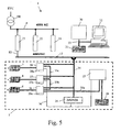
- Fig. 4 a diagram of an inventive electrical power supply of a shelf storage system
- Fig. 5 a block diagram of electrical and electronic components of a shelf storage system according to the invention.
- Fig. 1 shows a shelf storage system 1 according to the invention in a perspective view.
- the shelf storage system 1 is designed as a high-bay warehouse with four stacked shelves 1 a, 1 b, 1 c, 1 d.
- a pre-zone 1e has a lift system 3, which provides for the supply and removal of containers 4 to and from the individual rack aisles 1a-1d.
- the pre-zone 1 e comprises buffer means 1 f for temporarily storing containers 4 until they can be transferred to the lift system 3 or stored in shelves 2 arranged above and next to one another, of which each rack aisle is associated with a plurality.
- each rack aisle 1a - 1d For storage and retrieval of the container 4 in the shelves 2 a rack operating device 5 is provided in each rack aisle 1a - 1d, which is mechanically coupled to the associated rack aisle, so that it is movable in the rack aisle.
- the rack aisles are not particularly limited in length, the respective interpretation is carried out by the expert in consideration of the available base area and the increasing with increasing length travel times of the storage and retrieval units. Regal aisles over 100 m (eg up to 200 m) can be useful.
- the shelf storage system 1 is indeed designed as a high-bay system, but this is not essential for the invention.
- the shelf aisles can be arranged side by side or both side by side and one above the other. It is also understood that instead of containers for storing products in the shelf storage system according to the invention, the products to be stored can also be stored and stored directly in the shelves.
- FIG. 2 An embodiment of a storage and retrieval device 5 used in the invention is in Fig. 2 shown in side view.
- the storage and retrieval unit 5 has a lower drive module 5a and an upper drive module 5b, between which a mast 5c extends.
- an electric drive motor 6 is attached
- a further electric drive motor 7 is attached.
- the two drive motors are responsible for the process of the stacker crane 5 in the direction of the double arrow x.
- a further drive motor 8 is fixed, which ensures the lifting and lowering (in the direction of the double arrow y) of a 5 m attached to the mast 5c load receptor.
- On the load receptor 5d is a container 4.
- the load receptor 5d may be formed either as a gripper or as a lifter. In the first case, he takes and pulls container 4 from the shelves (in one direction out of the plane) or pushes container 4 on shelves, in the second case, it has a boom, not shown, which moves under shelves shelved container, raises and through Retracting retract the boom or turns off by the reverse movement in shelves.
- the storage and retrieval unit 5 can thus move containers 4 or products to be stored in three mutually orthogonal directions.
- the electric drive motors 6, 7, 8 are designed as DC position motors, which have integrated control units, so that no control cabinet must be provided on the storage and retrieval unit 5, which provides for a considerable weight savings.
- Fig. 3 is a front view of a section of the shelf storage system according to the invention to see, with an upper portion of the rack aisles 1a and a lower portion of the rack aisle 1b are shown. It can be seen in guide parts 1g, 1h arranged guide rails 19, 20, in which the two storage and retrieval units 5 of the rack aisles 1a, 1b are traversable. From the storage and retrieval unit 5 of the rack aisle 1b, the lower drive module 5a and a section of the truck mast 5c can be seen.
- the lower drive module 5a of the stacker crane 5 of the rack aisle 1b has on the left side two guide wheels 9, which run along the guide rail 19; on the right side also a pair of guide wheels 13 is provided which runs in the guide rail 20.
- the upper drive module 5b and a section of the mobile mast 5c are shown.
- two guide wheels 10 are provided, which run along the guide rail 19;
- a pair of guide wheels 17 is provided, which runs in the guide rail 20.
- the upper drive motor 7 attached to the upper drive module 5b drives a friction wheel 16 which, together with a counter-friction wheel 18, ensures slippage-free movement of the drive module 5b along the guide rail 20.
- a friction wheel 16 which, together with a counter-friction wheel 18, ensures slippage-free movement of the drive module 5b along the guide rail 20.
- a odometer 11 and a bus bar 12 of the rack aisle 1a shown.
- the odometer indicates the current, absolute or relative position of the storage and retrieval device 5 in the x direction.
- the busbar 12 supplies the Storage and retrieval unit 5 with electrical energy and receives from the drive motor 7 and the other drive motors of the storage and retrieval unit, not shown, regeneratively generated electrical energy.
- Fig. 4 a scheme of the electrical power supply of the shelf storage system 1 according to the invention is shown.
- the shelf storage system 1 is supplied by an energy supply company EVU electrical AC voltage of the required power, which is transformed in a transformer TR to a suitable voltage, for example, 400V AC.
- the transformed AC voltage is fed into a primary circuit P of the electrical power supply circuit of the shelf storage system.
- Energy converters 21, 22, 23, which are designed as AC / DC converters and convert the AC voltage supplied to them into a DC voltage of 600 V DC, are connected to the primary circuit P of the electrical power supply circuit.
- the output terminals of the energy converters 21, 22, 23 are each connected to an electrical intermediate circuit S1, S2, S3, wherein the intermediate circuits S2 and S3 respectively supply a bus bar 12 of a rack aisle 1a and 1b with electrical energy and the intermediate circuit S1 two busbars 12, ie the two rack aisles 1c and 1d supplied with electrical energy.
- each rack aisle traversable stacker crane 5 is connected via grinder, which can be moved via DC drive motors 6, 7 for horizontal movement of the stacker crane in the x-direction.
- Another DC motor 8 is provided for lifting movement of a load receiver in the y direction.
- the electric DC link S1 is designed such that energy fed back from a shelf storage device of a rack aisle 1c or 1d via the busbar 12 to the other rack aisle 1d or 1c is made available as required (double arrow ES1).
- the energy converters 21, 22, 23 are designed such that they are fed back into the primary circuit by the drive motors 6, 7, 8 of the stacker cranes 5 in the intermediate circuits S1, S2, S3 electrical energy that is currently not required in the respective intermediate circuits P back, where it is distributed as needed between the energy converters 21, 22, 23 (double arrow EP).
- Fig. 5 is a block diagram of electrical and electronic components of the shelf storage system. 1 and in particular a storage and retrieval unit 5 represents.
- the electric drive motors 6, 7, 8 are designed as position motors, which are DC motors with integrated or close to the engines in the stacker crane 5 arranged engine controllers 27, 28, 29. By providing the position motors can be dispensed to the storage and retrieval devices 5 on cabinets, which is a considerable reduction of the mass of up to 200 kg and a concomitant corresponding reduction of the required drive energy brings.
- the drive motors 6, 7, 8 and the electrical energy supply of the shelf storage system according to the invention are designed so that regenerated in the motors during braking regenerated electrical energy is fed back into the power supply circuit, can be dispensed with in contrast to conventional shelving systems in the stacker cranes invention electrical braking resistors , which are provided in conventional storage and retrieval devices for converting the electrical braking energy into heat.
- electrical braking resistors which are provided in conventional storage and retrieval devices for converting the electrical braking energy into heat.
- the distribution of the electric energy regeneratively generated by the motors 6, 7, 8 of a storage and retrieval unit expediently initially takes place among the other motors 7, 8, 6 of this storage and retrieval unit, e.g. in that the braking energy of the motors 6, 7 responsible for the movement of the storage and retrieval unit 5 in the x-direction is used to start the motor 8, which is responsible for the lifting movement of the load receiver.
- unused electrical energy is fed back to the DC link and - as far as a plurality of DC links are interconnected - divided among the DC buses. As far as the electrical energy can not be distributed in the intermediate circuits, it is fed back by the energy converters in the primary circuit P and distributed here.
- the motor controllers 27, 28, 29 are connected to one another via an industrial data bus 35a, 35b, 35c, such as PROFIBUS®, for example, and to a programmable logic controller 25 arranged on the storage and retrieval unit 5.
- the controller 25 ensures that the power generated by at least one drive motor of the stacker crane 5 regeneratively generated energy to the other drive motors of the storage and retrieval device available by corresponding sequences of motion of these motors are initiated.
- the motor controllers 27, 28, 29 and the programmable logic controller 25 are supplied via cables 36 with 24 V DC, this voltage is supplied by a voltage converter module 24, whose input is connected to the bus bar 12 of the intermediate circuit S3.
- the motors 6, 7, 8 in turn are supplied via the motor controller 27, 28, 29 of the bus bar 12 with 600 V DC.
- the programmable logic controller 25 is connected via wireless (eg optical or wireless) data couplers 29, 31 to a higher-level programmable logic controller 30 and to a central control computer 32, the data coupler 31, the controller 30 and the central control computer 32 also via an industrial data bus 33, such as PROFIBUS®, are interconnected.
- wireless eg optical or wireless
- the data coupler 31, the controller 30 and the central control computer 32 also via an industrial data bus 33, such as PROFIBUS®, are interconnected.
- the movements of all stacker cranes can be centrally coordinated and monitored by the higher-level programmable controller 30, including, for example, tasks such as determining the fed back from the drive motors of the stacker cranes in the power supply circuit electrical energy by detecting actual current values counting the stacker cranes.
- the higher-level programmable logic controller 30 or the central control computer 32 are also designed to run a program that ensures energy-saving operation of the shelf storage system 1 according to the invention.
- Such programs are known per se by the term "electrical load management" and control the operation of the stacker cranes so that the electrical power absorbed by them remains below a nominal power available for the entire rack storage system, for example by limiting the number of simultaneously moving stacker cranes or by reducing accelerations of the stacker cranes.
- an electrical load management is realized by taking into account in the control of the sequences of movement of the stacker cranes the electric energy fed back from storage and retrieval devices in the power supply circuit, the regenerated energy is used to set up stacker cranes or accelerate their movement.
- motion profiles are predefined, from which the movement sequences of the stacker cranes are assembled. These motion profiles include characteristic power consumption values or current output values of the drive profile executing the motion profile.
- the fed back by the drive motors in the power supply circuit electrical energy can therefore be from the estimate predefined movement profiles, from which the respective sequences of movements of the storage and retrieval units to be executed are composed.
Abstract
Description
Die Erfindung betrifft ein Regallagersystem mit zumindest zwei Regaleinheiten, wobei jede Regaleinheit ein eigenes verfahrbares Regalbediengerät mit elektrischen Antriebsmotoren aufweist, und mit einem elektrischen Energieversorgungskreis, um die Regaleinheiten mit elektrischer Energie zu versorgen.The invention relates to a shelf storage system with at least two shelf units, each shelf unit having its own movable storage and retrieval unit with electric drive motors, and with an electrical power supply circuit to supply the shelf units with electrical energy.
Ein solches Regallagersystem mit zumindest zwei Regaleinheiten ist beispielsweise aus der
Die Erfindung betrifft weiters ein Verfahren zum energlesparenden Betreiben von Regalbediengeräten in einem Regallagersystem, das einen elektrischen Energieversorgungskreis zur Versorgung der Regalbediengeräte mit elektrischer Energie aufweist, wobei die Regalbediengeräte elektrische Antriebsmotoren zum Ausführen von Bewegungssequenzen, wie z.B. Fahr- und Hubbewegungen, aufweisen und die Antriebsmotoren dazu ausgebildet sind, generatorisch von ihnen erzeugte elektrische Energie in den elektrischen Energieversorgungskreis rückzuspeisen.The invention further relates to a method for the energlesparenden operating of storage and retrieval equipment in a rack storage system having an electrical power supply circuit for supplying the storage and retrieval units with electrical energy, wherein the storage and retrieval units electric drive motors for carrying out motion sequences, such as. Driving and lifting movements, and the drive motors are designed to regenerate regenerated electrical energy generated by them in the electrical power supply circuit.
Regallagersysteme haben in den letzten Jahren eine solche Größe erreicht, dass mittlerweile oftmals das Problem besteht, die zum Betrieb der Regallagersysteme notwendige elektrische Energie bereitzustellen. Beispielsweise erfordern Regallagersysteme mit 25 Regalgassen oftmals die Bereitstellung einer elektrischen Leistung von 4 MVA und darüber. Da solch hohe elektrischen Leistungen an den Standorten der Regallagersysteme oftmals nicht verfügbar sind, müssen in solchen Fällen die Regallagersysteme unterhalb ihrer theoretisch möglichen Durchsatzleistung betrieben werden, indem beispielsweise nur eine bestimmte Anzahl von Regalbediengeräten zur gleichen Zeit bewegt wird, oder indem die Beschleunigungen der Regalbediengeräte drastisch reduziert werden, um somit eine geringere Stromaufnahme der elektrischen Antriebsmotoren der Regalbediengeräte zu bewirken, wodurch elektrische Lastspitzen vermieden werden. Es ist jedoch sowohl für die Erzeuger von Regallagersystemen als auch für deren Betreiber äußerst unbefriedigend, wenn aufgrund äußerer Umstände die theoretisch mögliche Leistungsfähigkeit der Regallagersysteme nicht ausgeschöpft werden kann. Dies umso mehr, als der Zeitdruck auf die Betreiber der Regallagersysteme aufgrund der mittlerweile allgemein verlangten "Just-in-time"-Lieferungen ständig steigt.Shelf storage systems have reached such a size in recent years that in the meantime there is often the problem of providing the electrical energy necessary for operating the shelf storage systems. For example, shelf storage systems with 25 rack aisles often require the provision of 4 MVA and above electrical power. Since such high electrical power at the locations of the shelf storage systems are often not available, the shelf storage systems must be operated below their theoretically possible throughput in such cases, for example, only a certain number of storage and retrieval equipment is moved at the same time, or by the accelerations of the storage and retrieval equipment drastically be reduced, thus causing a lower power consumption of the electric drive motors of the stacker cranes, whereby electrical load peaks are avoided. However, it is extremely unsatisfactory both for the producers of rack storage systems and for their operators, if due to external circumstances, the theoretically possible performance of the shelf storage systems can not be exhausted. All the more so as the time pressure on the operators of the shelf storage systems constantly increases due to the now generally demanded "just-in-time" deliveries.
Die
In der
Es besteht daher ein starkes Bedürfnis nach Regallagersystemen sowie Verfahren zum energiesparenden Betreiben von Regalbediengeräten in einem Regallagersystem, bei denen der elektrische Energiebedarf im Vergleich zu bekannten Regallagersystemen und Betriebsverfahren wesentlich reduziert ist.There is therefore a strong need for shelf storage systems and methods for energy-saving operation of storage and retrieval devices in a shelf storage system, in which the electrical energy requirement is substantially reduced compared to known shelf storage systems and operating methods.
Die vorliegende Erfindung löst dieses Problem durch Fortbilden des eingangs genannten Regallagersystems gemäß den kennzeichnenden Merkmalen des Anspruches 1 sowie durch Bereitstellen eines Verfahrens zum energiesparenden Betreiben von Regalbediengeräten in einem Regallagersystem mit den Merkmalen des Anspruches 11. Vorteilhafte Ausgestaltungen der Erfindung sind in den abhängigen Ansprüchen dargelegt.The present invention solves this problem by developing the aforementioned shelf storage system according to the characterizing features of
Das erfindungsgemäße Regallagersystem umfasst zumindest zwei Regaleinheiten, wobei jede Regaleinheit ein eigenes verfahrbares Regalbediengerät mit elektrischen Antriebsmotoren aufweist. Ein elektrischer Energieversorgungskreis versorgt die Regaleinheiten mit elektrischer Energie, wobei die Regalbediengeräte dazu ausgebildet sind generatorisch in ihren Antriebsmotoren erzeugte elektrische Energie in den elektrischen Energieversorgungskreis rückzuspeisen und der elektrische Energieversorgungskreis dazu ausgebildet ist von den Regalbediengeräten rückgespeiste elektrische Energie nach Bedarf zwischen den Regaleinheiten zu verteilen. Durch diese erfindungsgemäßen Maßnahmen ist es möglich, eine Energieersparnis von bis zu 20% gegenüber herkömmlichen Regallagersystemen zu erzielen.The shelf storage system according to the invention comprises at least two shelf units, each shelf unit having its own movable storage and retrieval unit with electric drive motors. An electrical power supply circuit supplies the shelf units with electrical energy, wherein the stacker cranes are designed to regenerate generated in their drive motors electrical energy generated in the electrical power supply circuit and the electrical power supply circuit is adapted to distribute from the stacker cranes fed back electrical energy as needed between the shelving units. By means of these measures according to the invention, it is possible to achieve an energy saving of up to 20% compared to conventional rack storage systems.
Um Regallagergassen von 100 Meter Länge und mehr, in denen sich jeweils ein Regalbediengerät bewegt, realisieren zu können, ist in einer bevorzugten Ausgestaltung der Erfindung vorgesehen, dass die Regalbediengeräte über Stromabnehmer, wie z.B. Schleifschienen, an den elektrischen Energieversorgungskreis angeschlossen sind. Man vermeidet dadurch die mit herkömmlichen Spiralkabeln verbundenen Probleme von Verwicklung und Bruch.In order to realize shelf storage aisles of 100 meters in length and more, in each of which a stacker crane moves, is provided in a preferred embodiment of the invention that the stacker cranes via pantographs, such as. Sliding rails connected to the electrical power supply circuit. This avoids the problems of entanglement and breakage associated with conventional spiral cables.
Für größere erfindungsgemäße Regallagersysteme erweist es sich als günstig, wenn zur Erhöhung der Stabilität der elektrischen Energieversorgung der elektrische Energieversorgungskreis einen mit einem Energieversorgungsnetz verbundenen Primärkreis und den Regaleinheiten zugeordnete Zwischenkreise aufweist, wobei zwischen den Primärkreis und die Zwischenkreise elektrische Energiewandler geschaltet sind. Zur Erzielung bestmöglichen Energieausgleichs über das gesamte Regallagersystem können in einer Ausgestaltung der Erfindung elektrische Energiewandler eingesetzt werden, die dazu ausgebildet sind, von den Regalbediengeräten in die Zwischenkreise rückgespeiste elektrische Energie in den Primärkreis rückzukoppeln. Dadurch kann die rückgespeiste Energie unter den Zwischenkreisen verteilt werden. Ergänzend oder alternativ dazu kann ein Zwischenkreis mehrere Regaleinheiten mit elektrischer Energie versorgen und der dem Zwischenkreis zugeordnete elektrische Energiewandler dazu ausgebildet sein, die in den Zwischenkreis rückgespeiste elektrische Energie nach Bedarf unter den an ihn angeschlossenen Regaleinheiten zu verteilen.For larger shelf storage systems according to the invention, it proves to be advantageous if, to increase the stability of the electrical energy supply, the electrical energy supply circuit has a primary circuit connected to a power supply network and the rack units associated intermediate circuits, wherein electrical energy converters are connected between the primary circuit and the intermediate circuits. In order to achieve the best possible energy balance over the entire shelf storage system electrical converter can be used in one embodiment of the invention, which are designed to feed back from the stacker cranes in the DC link-fed electrical energy into the primary circuit. As a result, the energy fed back can be distributed among the intermediate circuits. In addition or alternatively, a Intermediate supply several shelf units with electrical energy and the intermediate circuit associated electrical energy converter to be designed to distribute the fed back into the DC electric power as needed among the connected to it shelf units.
In einer besonders vorteilhaften Ausgestaltung des erfindungsgemäßen Regallagersystems ist der Primärkreis ein Wechselstromkreis und sind die Zwischenkreise als Gleichstromkreise ausgebildet, wobei die Energiewandler zwischen Primärkreis und den Zwischenkreisen als AC/DC-Wandler ausgebildet sind. Vorteilhaft sind die Antriebsmotoren der Regalbediengeräte als Gleichstrommotoren mit angeschlossenem Motorregler ausgebildet. Durch diese erfindungsgemäßen Maßnahmen kann gegenüber herkömmlichen Regallagersystemen, die mit Wechselstrom, insbesondere Drehstrom, betrieben werden, eine weitere Einsparung elektrischer Energie erzielt werden, die bis zu 50% betragen kann. Diese Einsparung ist darauf zurückzuführen, dass die Regalbediengeräte durch die Gleichstromtechnik und insbesondere das Zusammenspiel mit elektrischen Gleichstrommotoren mit integrierter Reglereinheit ohne Schaltschrank aufgebaut sein können, was eine Reduzierung der bewegten Masse um 150 bis 200 kg mit sich bringt.In a particularly advantageous embodiment of the shelf storage system according to the invention, the primary circuit is an AC circuit and the intermediate circuits are formed as DC circuits, wherein the energy converters between the primary circuit and the intermediate circuits are designed as AC / DC converter. Advantageously, the drive motors of the stacker cranes are designed as DC motors with attached motor controller. By means of these measures according to the invention, a further saving in electrical energy can be achieved compared to conventional rack storage systems which are operated with alternating current, in particular three-phase current, which can be up to 50%. This saving is due to the fact that the stacker cranes can be constructed by the DC technology and in particular the interaction with DC electric motors with integrated control unit without cabinet, resulting in a reduction in the mass moved by 150 to 200 kg with it.
Bei dem erfindungsgemäßen Regallagersystem sind die Regalbediengeräte mit solchen Antriebsmotoren versehen, die bei Bremsvorgängen generatorisch in ihnen erzeugte elektrische Energie in den elektrischen Energieversorgungskreis rückspeisen. Dadurch ist es in weiterer Ausgestaltung der Erfindung möglich, bei den Regalbediengeräten auf elektrische Bremswiderstände zu verzichten, die bei herkömmlichen Regalbediengeräten dazu benutzt werden, die kinetische Bremsenergie als Wärmeenergie abzubauen. Durch die erfindungsgemäße Maßnahme wird eine weitere Verringerung der Masse der Regalbediengeräte erreicht und es bestehen keine Probleme mit der Wärmeabfuhr. Durch den Verzicht auf Bremswiderstände können die Regalbediengeräte auch billiger gebaut werden als herkömmlich.In the shelf storage system according to the invention, the stacker cranes are provided with such drive motors that regenerate in braking processes in their generated electrical energy in the electrical power supply circuit. This makes it possible in a further embodiment of the invention to dispense with the stacker cranes on electrical braking resistors that are used in conventional storage and retrieval devices to reduce the kinetic energy of braking as thermal energy. The inventive measure a further reduction in the mass of the stacker cranes is achieved and there are no problems with the heat dissipation. By dispensing with braking resistors, the stacker cranes can also be built cheaper than conventional.
Um am erfindungsgemäßen Regallagersystem ein elektrisches Lastmanagement betreiben zu können, sind in weiterer Ausgestaltung der Erfindung an den Regalbediengeräten Sensoren zur Ermittlung der elektrischen Strom- oder Leistungsaufnahme oder -abgabe der Antriebsmotoren vorgesehen. Für die Realisierung des Lastmanagement ist es vorteilhaft, wenn ein Steuerrechner vorgesehen ist, der Bewegungssequenzen der Regalbediengeräte so steuert, dass von Regalbediengeräten in den Energieversorgungskreis rückgespeiste elektrische Energie zum Ingangsetzen oder Beschleunigen von Bewegungssequenzen anderer Regalbediengeräte verwendet wird.In order to be able to operate an electrical load management on the shelf storage system according to the invention, sensors for determining the electric current or power consumption or output of the drive motors are provided in a further embodiment of the invention on the storage and retrieval units. For the realization of the load management, it is advantageous if a control computer is provided, the movement sequences of the stacker cranes controls so that returned from stacker cranes in the power supply circuit electrical energy for starting or accelerating sequences of movement of other storage and retrieval devices.
Das erfindungsgemäße Verfahren zum energiesparenden Betreiben von Regalbediengeräten in einem Regallagersystem, das einen elektrischen Energieversorgungskreis zur Versorgung der Regalbediengeräte mit elektrischer Energie aufweist, wobei die Regalbediengeräte elektrische Antriebsmotoren zum Ausführen von Bewegungssequenzen, wie z.B. Fahr- und Hubbewegungen, aufweisen und die Antriebsmotoren dazu ausgebildet sind, generatorisch von ihnen erzeugte elektrische Energie in den elektrischen Energieversorgungskreis rückzuspeisen, zeichnet sich dadurch aus, dass die Bewegungssequenzen so gesteuert werden, dass von zumindest einem Antriebsmotor in den Energieversorgungskreis rückgespeiste elektrische Energie zum Ingangsetzen oder Beschleunigen von anderen Antriebsmotoren verwendet wird. Durch dieses Lastmanagementverfahren sind bis zu 20% des Verbrauchs elektrischer Energie im Vergleich zu herkömmlichen Lastmanagementverfahren einsparbar.The inventive method for energy-saving operation of storage and retrieval devices in a rack storage system having an electrical power supply circuit for supplying the storage and retrieval units with electrical energy, wherein the storage and retrieval units electric drive motors for carrying out motion sequences, such as. Driving and lifting movements, and the drive motors are designed to regenerate regenerated electrical energy generated by them in the electrical power supply circuit, characterized in that the movement sequences are controlled so that at least one drive motor in the power supply circuit fed back electric energy to start or accelerating is used by other drive motors. As a result of this load management method, up to 20% of the consumption of electrical energy can be saved in comparison to conventional load management methods.
Gemäß einer Variante des erfindungsgemäßen Verfahrens wird die von dem zumindest einen Antriebsmotor in den Energieversorgungskreis rückgespeiste elektrische Energie zum Ingangsetzen oder Beschleunigen von anderen Antriebsmotoren desselben Regalbediengerätes verwendet, wobei vorzugsweise die Steuerung der Bewegungssequenz direkt am Regalbediengerät erfolgt. Diese dezentrale Steuerung der Bewegungssequenz direkt am Regalbediengerät entlastet einen übergeordneten zentralen Steuerrechner erheblich. Alternativ dazu kann zugunsten einer möglichst gleichmäßigen Verteilung der rückgespeisten elektrischen Energie über das gesamte Regalsystem eine höhere Belastung eines zentralen Steuerrechners in Kauf genommen werden, indem die von dem zumindest einen Antriebsmotor in den Energieversorgungskreis rückgespeiste elektrische Energie zum Ingangsetzen oder Beschleunigen von Antriebsmotoren anderer Regalbediengeräte unter Steuerung durch den zentralen Steuerrechner verwendet wird. Eine regeltechnisch günstige Variante des erfindungsgemäßen Verfahrens ist dadurch gekennzeichnet, dass die von den Antriebsmotoren in den Energieversorgungskreis rückgespeiste elektrische Energie durch Erfassung von Ist-Stromwerten an den Regalbediengeräten ermittelt wird.According to a variant of the method according to the invention, the electric energy fed back by the at least one drive motor into the energy supply circuit is used to start up or accelerate other drive motors of the same storage and retrieval unit, wherein preferably the control sequence of the movement sequence takes place directly on the storage and retrieval unit. This decentralized control of the sequence of movements directly on the storage and retrieval unit significantly relieves a higher-level central control computer. Alternatively, a higher burden of a central control computer can be accepted in favor of a uniform distribution of the returned electrical energy over the entire rack system by the at least one drive motor in the power supply circuit fed back electrical energy for starting or accelerating drive motors of other storage and retrieval units under control is used by the central control computer. A control-technically advantageous variant of the method according to the invention is characterized in that the electric energy fed back by the drive motors into the energy supply circuit is determined by detecting actual current values at the storage and retrieval units.
Es erweist sich für eine einfache und stabile Regelung als vorteilhaft, wenn Bewegungsprofile vordefiniert werden, aus denen sich die Bewegungssequenzen der Regalbediengeräte zusammensetzten lassen, wobei die Bewegungsprofile charakteristische Stromverbrauchswerte bzw. Stromabgabewerte der das Bewegungsprofil ausführenden Antriebsmotoren umfassen, und die von den Antriebsmotoren in den Energieversorgungskreis rückgespeiste elektrische Energie aus den vordefinierten Bewegungsprofilen abgeschätzt wird, aus denen die jeweiligen auszuführenden Bewegungssequenzen der Regalbediengeräte zusammengesetzt sind.It proves to be advantageous for a simple and stable control when motion profiles are predefined from which the sequences of movements of the storage and retrieval devices can be put together, wherein the movement profiles comprise characteristic power consumption values or current output values of the drive profile executing drive motors, and those of the drive motors in the power supply circuit Recovered electrical energy from the predefined Movement profiles is estimated, from which the respective sequences of movements of the stacker cranes are composed.
Die Erfindung wird nun im Folgenden anhand eines nicht einschränkenden Ausführungsbeispiels unter Bezugnahme auf die Zeichnungen näher erläutert.The invention will now be explained in more detail below with reference to a non-limiting embodiment with reference to the drawings.
In den Zeichnungen zeigen:
Ein Ausführungsbeispiel eines in der Erfindung verwendeten Regalbediengerätes 5 ist in
In
In
Weiters sind die Energiewandler 21, 22, 23 so ausgebildet, dass sie von den Antriebsmotoren 6, 7, 8 der Regalbediengeräte 5 in die Zwischenkreise S1, S2, S3 zurückgespeist elektrische Energie, die aktuell in den jeweiligen Zwischenkreisen nicht benötigt wird, in den Primärkreis P zurückspeisen, wo sie nach Bedarf zwischen den Energiewandlern 21, 22, 23 verteilt wird (Doppelpfeil EP).Furthermore, the
Für die folgende Beschreibung wird nun auch auf
Zweckmäßig erfolgt die Verteilung der von den Motoren 6, 7, 8 eines Regalbediengerätes generatorisch erzeugten elektrischen Energie zunächst unter den anderen Motoren 7, 8, 6 dieses einen Regalbediengerätes, z.B. indem die Bremsenergie der für die Bewegung des Regalbediengerätes 5 in x-Richtung zuständigen Motoren 6, 7 zum Ingangsetzen des Motors 8 genutzt wird, der für die Hubbewegung des Lastaufnehmers zuständig ist. In dem Regalbediengerät 5 nicht verbrauchte elektrische Energie wird weiter an den Zwischenkreis rückgespeist und - soweit mehrere Zwischenkreise miteinander verbunden sind - unter den Zwischenkreisen aufgeteilt. Soweit die elektrische Energie nicht in den Zwischenkreisen verteilt werden kann, wird sie von den Energiewandlern in den Primärkreis P rückgespeist und hier verteilt.The distribution of the electric energy regeneratively generated by the
Die Motorregler 27, 28, 29, sind über einen industriellen Datenbus 35a, 35b, 35c, wie z.B. PROFIBUS®, miteinander und mit einer am Regalbediengerät 5 angeordneten speicherprogrammierbaren Steuerung 25 verbunden. Die Steuerung 25 sorgt dafür, die von zumindest einem Antriebsmotor des Regalbediengerätes 5 generatorisch erzeugte Energie den anderen Antriebsmotoren des Regalbediengerätes zur Verfügung zu stellen, indem entsprechende Bewegungssequenzen dieser Motoren initiiert werden.The
Die Motorregler 27, 28, 29 und die speicherprogrammierbare Steuerung 25 werden über Kabel 36 mit 24 V DC versorgt, wobei diese Spannung von einem Spannungswandlermodul 24 geliefert wird, dessen Eingang mit der Stromschiene 12 des Zwischenkreises S3 verbunden ist. Die Motoren 6, 7, 8 wiederum werden über die Motorregler 27, 28, 29 von der Stromschiene 12 mit 600 V DC versorgt.The
Die speicherprogrammierbare Steuerung 25 ist über drahtlose (z.B. optische oder Funk-) Datenkoppler 29, 31 mit einer übergeordneten speicherprogrammierbaren Steuerung 30 und mit einem zentralen Steuerrechner 32 verbunden, wobei der Datenkoppler 31, die Steuerung 30 und der zentrale Steuerrechner 32 ebenfalls über einen industriellen Datenbus 33, wie z.B. PROFIBUS®, miteinander verbunden sind. Durch die Vernetzung aller Steuergeräte des Regallagersystems können die Bewegungen aller Regalbediengeräte von der übergeordneten speicherprogrammierbaren Steuerung 30 zentral koordiniert und überwacht werden, wozu beispielsweise auch Aufgaben wie das Ermitteln der von den Antriebsmotoren der Regalbediengeräte in den Energieversorgungskreis rückgespeisten elektrischen Energie durch Erfassung von Ist-Stromwerten an den Regalbediengeräten zählen.The
Die übergeordnete speicherprogrammierbare Steuerung 30 oder der zentrale Steuerrechner 32 sind auch dafür vorgesehen, ein Programm ablaufen zu lassen, das für einen energiesparenden Betrieb des erfindungsgemäßen Regallagersystems 1 sorgt. Solche Programme sind an sich unter dem Begriff "elektrisches Lastmanagement" bekannt und steuern den Betrieb der Regalbediengeräte so, dass die von ihnen aufgenommene elektrische Leistung unterhalb einer für das gesamte Regallagersystem zur Verfügung stehenden Nennleistung bleibt, beispielsweise indem die Anzahl der gleichzeitig bewegten Regalbediengeräte limitiert wird oder indem Beschleunigungen der Regalbediengeräte reduziert werden. Erfindungsgemäß wird ein elektrisches Lastmanagement jedoch dadurch realisiert, indem bei der Steuerung der Bewegungssequenzen der Regalbediengeräte die von Regalbediengeräten in den Energieversorgungskreis rückgespeiste elektrische Energie berücksichtigt wird, wobei die rückgespeiste Energie dazu ausgenutzt wird, Regalbediengeräte in Gang zu setzen oder ihre Bewegung zu beschleunigen.The higher-level
In einer bevorzugten Ausgestaltung des erfindungsgemäßen elektrischen Lastmanagement-Verfahrens werden Bewegungsprofile vordefiniert, aus denen die Bewegungssequenzen der Regalbediengeräte zusammengesetzt werden. Diese Bewegungsprofile umfassen charakteristische Stromverbrauchswerte bzw. Stromabgabewerte der das Bewegungsprofil ausführenden Antriebsmotoren. Die von den Antriebsmotoren in den Energieversorgungskreis rückgespeiste elektrische Energie lässt sich daher aus den vordefinierten Bewegungsprofilen, aus denen die jeweiligen auszuführenden Bewegungssequenzen der Regalbediengeräte zusammengesetzt sind, abschätzen.In a preferred embodiment of the electrical load management method according to the invention, motion profiles are predefined, from which the movement sequences of the stacker cranes are assembled. These motion profiles include characteristic power consumption values or current output values of the drive profile executing the motion profile. The fed back by the drive motors in the power supply circuit electrical energy can therefore be from the estimate predefined movement profiles, from which the respective sequences of movements of the storage and retrieval units to be executed are composed.
Die Vorteile und Vorzüge der vorliegenden Erfindung lassen sich folgendermaßen zusammenfassen:
- Geringerer Energieverbrauch durch regalgassenübergreifende Nutzung generatorisch erzeugter Energie.
- Durch das Zusammenspiel von Gleichstromversorgung der Zwischenkreise mit dem dezentralen Positionsmotor-Antriebssystem (Antriebe mit integrierter Reglereinheit) ist ein nahezu schaltschrankloser Aufbau der Regalbediengeräte möglich.
- Gewichtsersparnis und dadurch Ersparnis der zu bewegenden Massen (Energieersparnis) durch den nahezu schaltschrank losen Aufbau.
- Durch Rückeinspeisung der generatorisch erzeugten Energie über die Stromabnehmer in den Zwischenkreis sind keine Bremswiderstände am Regalbediengerät nötig. Nachteil der Bremswiderstände sind Kosten, Platzbedarf und Probleme mit der Abfuhr der erzeugten Wärme.
- Lower energy consumption due to the use of generator-generated energy across the shelf.
- Due to the interplay of DC power supply of the DC link with the decentralized position motor drive system (drives with integrated controller unit), it is possible to build up the stacker cranes without the need for a control cabinet.
- Weight savings and thus savings of masses to be moved (energy savings) through the almost cabinet-free design.
- By feeding back the regeneratively generated energy via the current collector into the DC link, no braking resistors are required on the stacker crane. Disadvantage of the braking resistors are costs, space requirements and problems with the dissipation of the heat generated.
Claims (14)
- A shelf storage system (1) comprising at least two shelf units (1a-1d), wherein each shelf unit has a separate moveable shelf feeder device (5) with electric drive motors (6, 7, 8), and comprising an electric energy supply circuit (P, S1, S2, S3) for supplying the shelf units (1a-1d) with electric energy, characterized in that the shelf feeder devices (5) are connected to the electric energy supply circuit (S1, S2, S3) via electric energy transmission devices, in particular collectors such as, e.g., conductor rails (12) and, via the electric energy transmission devices, recycle electric energy produced in their drive motors (6, 7, 8) by being operated as generators back into the electric energy supply circuit, with the electric energy supply circuit distributing electric energy recycled by the shelf feeder devices to other shelf feeder devices (5) in the shelf units (arrow ES1, arrow EP).
- A shelf storage system according to claim 1, characterized in that the electric energy supply circuit comprises a primary circuit (P) connected to an energy supply network (EVU) and intermediate circuits (S1, S2, S3) allocated to the shelf units (1a, 1b, 1c, 1d), with electric energy converters (21, 22, 23) being interposed between the primary circuit and the intermediate circuits.
- A shelf storage system according to claim 2, characterized in that the electric energy converters (21, 22, 23) are designed for recycling electric energy back into the primary circuit (P), which electric energy has been fed back into the intermediate circuits by the shelf feeder devices (5).
- A shelf storage system according to claim 2 or 3, characterized in that one intermediate circuit (S1) supplies several shelf units (1c, 1d) with electric energy and the electric energy converter (21) associated to the intermediate circuit (S1) is designed for distributing the electric energy fed back into the intermediate circuit (S1) among the shelf units (1c, 1d) connected to the same, according to requirements.
- A shelf storage system according to any of claims 2 to 4, characterized in that the primary circuit (P) is an alternating current circuit, the intermediate circuits (S1, S2, S3) are direct current circuits and the energy converters (21, 22, 23) are designed as AC/DC converters.
- A shelf storage system according to claim 5, characterized in that the drive motors (6, 7, 8) of the shelf feeder devices (5) are designed as direct current motors with an attached motor controller (26, 27, 28).
- A shelf storage system according to any of the preceding claims, characterized in that the shelf feeder devices (5) are designed without electric braking resistors.
- A shelf storage system according to any of the preceding claims, characterized in that the shelf feeder devices (5) are provided with sensors (26a, 27a, 28a) for detecting the electric current or power consumption or delivery of the drive motors.
- A shelf storage system according to any of the preceding claims, characterized in that a control computer (30, 32) is provided which is designed for controlling motion sequences of the shelf feeder devices such that electric energy fed back into the energy supply circuit by shelf feeder devices is used for activating or accelerating motion sequences of the shelf feeder devices.
- A process for the energy-saving operation of shelf feeder devices (5) in a shelf storage system (1) which has an electric energy supply circuit for supplying the shelf feeder devices with electric energy, wherein the shelf feeder devices have electric drive motors (6, 7, 8) for performing motion sequences such as, e.g., driving and lifting motions and the drive motors are designed for recycling electric energy produced by them by being operated as generators back into the electric energy supply circuit, characterized in that the motion sequences are controlled such that electric energy fed back into the energy supply circuit by at least one drive motor (6, 7, 8) is used for activating or accelerating other drive motors (7, 8, 6).
- A process according to claim 10, characterized in that the electric energy fed back into the energy supply circuit by the at least one drive motor (6, 7, 8) is used for activating or accelerating other drive motors (7, 8, 6) of the same shelf feeder device (5), with the control of the motion sequence preferably occurring directly at the shelf feeder device.
- A process according to claim 10, characterized in that the electric energy fed back into the energy supply circuit by the at least one drive motor (7, 8, 6) is used for activating or accelerating drive motors of other shelf feeder devices (5), with central control computers (30, 32) exerting control.
- A process according to any of claims 10 to 12, characterized in that the electric energy fed back into the energy supply circuit by the drive motors (6, 7, 8) is ascertained by determining actual current values at the shelf feeder devices.
- A process according to any of claims 10 to 12, characterized by predefining motion profiles from which the motion sequences of the shelf feeder devices (5) can be assembled, with the motion profiles comprising characteristic current consumption values and current delivery values, respectively, of the drive motors (6, 7, 8) performing the motion profile, and by evaluating the electric energy fed back into the energy supply circuit by the drive motors from the predefined motion profiles from which the respective motion sequences of the shelf feeder devices which are to be performed are assembled.
Priority Applications (1)
| Application Number | Priority Date | Filing Date | Title |
|---|---|---|---|
| AT05734875T ATE434859T1 (en) | 2004-05-28 | 2005-04-29 | SHELF STORAGE SYSTEM WITH ENERGY FEEDBACK |
Applications Claiming Priority (2)
| Application Number | Priority Date | Filing Date | Title |
|---|---|---|---|
| AT0093504A AT502079B1 (en) | 2004-05-28 | 2004-05-28 | SHELVING SYSTEM WITH ENERGY RECYCLING |
| PCT/AT2005/000148 WO2005117248A1 (en) | 2004-05-28 | 2005-04-29 | Shelf storage system with energy recycling |
Publications (3)
| Publication Number | Publication Date |
|---|---|
| EP1749341A1 EP1749341A1 (en) | 2007-02-07 |
| EP1749341B1 true EP1749341B1 (en) | 2009-06-24 |
| EP1749341B2 EP1749341B2 (en) | 2020-07-01 |
Family
ID=34965412
Family Applications (1)
| Application Number | Title | Priority Date | Filing Date |
|---|---|---|---|
| EP05734875.7A Active EP1749341B2 (en) | 2004-05-28 | 2005-04-29 | Shelf storage system with energy recycling |
Country Status (6)
| Country | Link |
|---|---|
| US (1) | US7646156B2 (en) |
| EP (1) | EP1749341B2 (en) |
| AT (2) | AT502079B1 (en) |
| DE (1) | DE502005007573D1 (en) |
| ES (1) | ES2328499T5 (en) |
| WO (1) | WO2005117248A1 (en) |
Cited By (1)
| Publication number | Priority date | Publication date | Assignee | Title |
|---|---|---|---|---|
| WO2016094923A2 (en) | 2014-12-18 | 2016-06-23 | Tgw Logistics Group Gmbh | Storage system having improved energy compensation among stacker cranes |
Families Citing this family (20)
| Publication number | Priority date | Publication date | Assignee | Title |
|---|---|---|---|---|
| DE102005030084B4 (en) * | 2005-06-27 | 2021-01-21 | Sew-Eurodrive Gmbh & Co Kg | Track-guided transport vehicle with lifting platform and energy storage |
| JP5037244B2 (en) | 2006-07-10 | 2012-09-26 | ハイデルベルガー ドルツクマシーネン アクチエンゲゼルシヤフト | Controlled energy consumption of the electric drive in the machine |
| DE102007020184B4 (en) * | 2006-09-01 | 2020-02-06 | Sew-Eurodrive Gmbh & Co Kg | Method and device for motion control of axes |
| DE102006043299A1 (en) * | 2006-09-14 | 2008-03-27 | Psb Intralogistics Gmbh | Method for minimizing the energy consumption of a warehouse |
| DE102007045433A1 (en) * | 2007-09-22 | 2009-04-09 | SIBEA GmbH Ingenieurbetrieb für Elektroautomation | Energy management for the drive of assemblies for processing and / or transport processes on machines and plants |
| DE102009024357A1 (en) | 2009-06-09 | 2010-12-16 | Psb Intralogistics Gmbh | Industrial system for electrical energy supply of e.g. loads, has power supply device designed without using brake unit so that energy is stored for recovery of energy nor interrupted for non-utilization in controlled manner |
| DE102009056447A1 (en) * | 2009-12-01 | 2011-06-09 | Deutsches Zentrum für Luft- und Raumfahrt e.V. | Electric motors e.g. brushless direct current motors, total current limiting method for e.g. motor vehicle, involves lowering current or speed parameter so that determined total current does not exceed maximum allowed total current |
| DE102010007275B4 (en) | 2010-02-08 | 2020-03-05 | Sew-Eurodrive Gmbh & Co Kg | Drive system and method for operating a drive system |
| DE102010020124B4 (en) * | 2010-05-10 | 2020-07-30 | Sew-Eurodrive Gmbh & Co Kg | Method for operating a vehicle, device for carrying out the method and use of an output signal |
| JP5212428B2 (en) | 2010-07-08 | 2013-06-19 | 村田機械株式会社 | Traveling vehicle system |
| DE102012002870B4 (en) * | 2012-02-13 | 2015-10-22 | Jorge Luis Sanchez Vargas | Generator and / or motor station for a system for on-demand storage and / or delivery of electrical energy |
| DE102012002869B4 (en) * | 2012-02-13 | 2016-02-18 | Jorge Luis Sanchez Vargas | Magnetic working means for a generator and / or motor station of a system for the need-based storage and / or delivery of electrical energy |
| DE102012002868B4 (en) * | 2012-02-13 | 2016-03-24 | Jorge Luis Sanchez Vargas | Generator and / or motor station for a system for the requirement of storing electrical energy and / or output of electrical energy |
| DE102012002867B4 (en) * | 2012-02-13 | 2016-04-21 | Jorge Luis Sanchez Vargas | Generator and / or motor station for a system for on-demand storage and / or delivery of electrical energy |
| DE102012006163B4 (en) * | 2012-03-28 | 2020-09-17 | Sew-Eurodrive Gmbh & Co Kg | Storage system, in particular shelf storage, with load handling means, in particular storage and retrieval unit, for storing or retrieving objects and a method for operating a storage system |
| DE102018105681A1 (en) * | 2018-03-12 | 2019-09-12 | Lenze Drives Gmbh | Method for controlling a stacker crane |
| DE102019001936A1 (en) * | 2019-03-20 | 2020-09-24 | Günther Zimmer | Energy supply system for a transport and / or processing system |
| EP3733560A1 (en) * | 2019-04-30 | 2020-11-04 | IMA Schelling Austria GmbH | Plate warehouse |
| CN113213371B (en) * | 2021-04-29 | 2022-03-04 | 腾达航勤设备(无锡)有限公司 | Electric energy regeneration system for containerized cargo loader |
| CN117177921A (en) | 2021-05-12 | 2023-12-05 | 索尤若驱动有限及两合公司 | Method for operating a warehouse system and warehouse system |
Family Cites Families (12)
| Publication number | Priority date | Publication date | Assignee | Title |
|---|---|---|---|---|
| DE3812312A1 (en) | 1988-04-13 | 1989-11-02 | Rexroth Mannesmann Gmbh | Hydraulic drive for a belt conveyor |
| JP2645159B2 (en) | 1989-12-12 | 1997-08-25 | 株式会社東芝 | Induction machine control device |
| JP3001377B2 (en) * | 1994-08-08 | 2000-01-24 | ファナック株式会社 | Power outage control method and device |
| GB2300612B (en) * | 1995-04-25 | 1998-09-30 | Crisplant As | Conveyor |
| US5704250A (en) * | 1996-04-04 | 1998-01-06 | Western Atlas, Inc. | Ball screw drive with dynamically adjustable preload |
| DE19831204A1 (en) * | 1998-07-01 | 2000-01-05 | Thomas Keese | Operation of e.g. trams, to enable power of sub-networks supplying sections of track to be reduced |
| DE19845527A1 (en) * | 1998-10-02 | 2000-04-06 | Beumer Maschf Bernhard | Link conveyor (sorter) for sorting piece goods |
| EP1061035A2 (en) * | 1999-06-10 | 2000-12-20 | Murata Kikai Kabushiki Kaisha | Stacker crane |
| JP2000355405A (en) | 1999-06-16 | 2000-12-26 | Nippon Yusoki Co Ltd | Brake controller for stacker crane |
| JP4452399B2 (en) | 2000-01-13 | 2010-04-21 | フジテック株式会社 | AC elevator power supply |
| JP3560899B2 (en) | 2000-05-10 | 2004-09-02 | 株式会社三協精機製作所 | Motor driving method and driving device |
| DE20112328U1 (en) | 2001-07-26 | 2002-01-31 | Knapp Logistik Automation | Order picking system with a container rack and assigned rack operating device |
-
2004
- 2004-05-28 AT AT0093504A patent/AT502079B1/en active
-
2005
- 2005-04-29 DE DE502005007573T patent/DE502005007573D1/en active Active
- 2005-04-29 WO PCT/AT2005/000148 patent/WO2005117248A1/en active Application Filing
- 2005-04-29 US US11/569,667 patent/US7646156B2/en active Active
- 2005-04-29 ES ES05734875T patent/ES2328499T5/en active Active
- 2005-04-29 AT AT05734875T patent/ATE434859T1/en active
- 2005-04-29 EP EP05734875.7A patent/EP1749341B2/en active Active
Cited By (1)
| Publication number | Priority date | Publication date | Assignee | Title |
|---|---|---|---|---|
| WO2016094923A2 (en) | 2014-12-18 | 2016-06-23 | Tgw Logistics Group Gmbh | Storage system having improved energy compensation among stacker cranes |
Also Published As
| Publication number | Publication date |
|---|---|
| AT502079A1 (en) | 2007-01-15 |
| US20090021023A1 (en) | 2009-01-22 |
| ES2328499T3 (en) | 2009-11-13 |
| EP1749341B2 (en) | 2020-07-01 |
| ES2328499T5 (en) | 2021-04-14 |
| EP1749341A1 (en) | 2007-02-07 |
| US7646156B2 (en) | 2010-01-12 |
| ATE434859T1 (en) | 2009-07-15 |
| WO2005117248A1 (en) | 2005-12-08 |
| AT502079B1 (en) | 2007-05-15 |
| DE502005007573D1 (en) | 2009-08-06 |
Similar Documents
| Publication | Publication Date | Title |
|---|---|---|
| EP1749341B1 (en) | Shelf storage system with energy recycling | |
| EP3038950B1 (en) | Automatic rack storage system and corresponding method | |
| EP3419918A1 (en) | Storage and retrieval device for parallel operation of a high-bay warehouse and operating method therefor | |
| DE102007026012B4 (en) | Controlled energy consumption of electric drives in machines | |
| EP2566788A1 (en) | Storage and order-picking system comprising a shuttle | |
| DE102010007275B4 (en) | Drive system and method for operating a drive system | |
| EP2477917B1 (en) | Roller conveyor and method for operating it | |
| WO2012113679A1 (en) | Shuttle for a storage and order-picking system | |
| EP1637477A2 (en) | System with stationary and movable functional devices | |
| AT519139B1 (en) | Storage and retrieval unit and shelf storage system with improved accessibility and weight distribution | |
| WO2005090116A1 (en) | Magnet arrangement for a magnetic levitation vehicle | |
| DE1756746A1 (en) | Automatic cargo handling device | |
| EP2060001B1 (en) | Method for controlling the motion of axes and device for carrying out this method | |
| DE102019131365A1 (en) | Warehouse with at least one shelf unit | |
| EP3704000A1 (en) | Method and vehicle for conveying an electrically driven motor vehicle during assembly thereof | |
| EP3006389B1 (en) | Stacker crane and method for controlling a stacker crane | |
| WO2022043279A2 (en) | Shuttle for a shelf system, and shelf system | |
| EP2259949B1 (en) | Power storage system for a rail-guided vehicle | |
| DE102015111553A1 (en) | Device and method for inductive transmission of electrical energy | |
| WO2008031608A1 (en) | Method and apparatus for minimizing the electrical energy drawn by an industrial installation | |
| EP3543200A1 (en) | Method of controlling shelf access equipment | |
| DE102010033596A1 (en) | Robot system for use in e.g. frame-and-body construction, has intermediate circuits coupled together, so that electrical energy produced by drives i.e. synchronous servo motors, stays in one of intermediate circuits of robot | |
| DE102018105300A1 (en) | DC TRANSMISSION OVER POWER RAILS | |
| DE102011122427A1 (en) | Manufacturing and transportation arrangement i.e. robot system, for use in assembly line of automobile industry, has electrical intermediate circuits electrically connected with adjacent circuit by respective power converters | |
| EP2844603B1 (en) | Conveyor frame |
Legal Events
| Date | Code | Title | Description |
|---|---|---|---|
| PUAI | Public reference made under article 153(3) epc to a published international application that has entered the european phase |
Free format text: ORIGINAL CODE: 0009012 |
|
| 17P | Request for examination filed |
Effective date: 20061123 |
|
| AK | Designated contracting states |
Kind code of ref document: A1 Designated state(s): AT BE BG CH CY CZ DE DK EE ES FI FR GB GR HU IE IS IT LI LT LU MC NL PL PT RO SE SI SK TR |
|
| 17Q | First examination report despatched |
Effective date: 20070323 |
|
| DAX | Request for extension of the european patent (deleted) | ||
| GRAP | Despatch of communication of intention to grant a patent |
Free format text: ORIGINAL CODE: EPIDOSNIGR1 |
|
| GRAS | Grant fee paid |
Free format text: ORIGINAL CODE: EPIDOSNIGR3 |
|
| GRAA | (expected) grant |
Free format text: ORIGINAL CODE: 0009210 |
|
| AK | Designated contracting states |
Kind code of ref document: B1 Designated state(s): AT BE BG CH CY CZ DE DK EE ES FI FR GB GR HU IE IS IT LI LT LU MC NL PL PT RO SE SI SK TR |
|
| REG | Reference to a national code |
Ref country code: GB Ref legal event code: FG4D Free format text: NOT ENGLISH |
|
| REG | Reference to a national code |
Ref country code: CH Ref legal event code: EP |
|
| REG | Reference to a national code |
Ref country code: IE Ref legal event code: FG4D Free format text: LANGUAGE OF EP DOCUMENT: GERMAN |
|
| REF | Corresponds to: |
Ref document number: 502005007573 Country of ref document: DE Date of ref document: 20090806 Kind code of ref document: P |
|
| PG25 | Lapsed in a contracting state [announced via postgrant information from national office to epo] |
Ref country code: LT Free format text: LAPSE BECAUSE OF FAILURE TO SUBMIT A TRANSLATION OF THE DESCRIPTION OR TO PAY THE FEE WITHIN THE PRESCRIBED TIME-LIMIT Effective date: 20090624 Ref country code: FI Free format text: LAPSE BECAUSE OF FAILURE TO SUBMIT A TRANSLATION OF THE DESCRIPTION OR TO PAY THE FEE WITHIN THE PRESCRIBED TIME-LIMIT Effective date: 20090624 |
|
| REG | Reference to a national code |
Ref country code: ES Ref legal event code: FG2A Ref document number: 2328499 Country of ref document: ES Kind code of ref document: T3 |
|
| PG25 | Lapsed in a contracting state [announced via postgrant information from national office to epo] |
Ref country code: PL Free format text: LAPSE BECAUSE OF FAILURE TO SUBMIT A TRANSLATION OF THE DESCRIPTION OR TO PAY THE FEE WITHIN THE PRESCRIBED TIME-LIMIT Effective date: 20090624 Ref country code: SI Free format text: LAPSE BECAUSE OF FAILURE TO SUBMIT A TRANSLATION OF THE DESCRIPTION OR TO PAY THE FEE WITHIN THE PRESCRIBED TIME-LIMIT Effective date: 20090624 Ref country code: SE Free format text: LAPSE BECAUSE OF FAILURE TO SUBMIT A TRANSLATION OF THE DESCRIPTION OR TO PAY THE FEE WITHIN THE PRESCRIBED TIME-LIMIT Effective date: 20090924 |
|
| NLV1 | Nl: lapsed or annulled due to failure to fulfill the requirements of art. 29p and 29m of the patents act | ||
| PG25 | Lapsed in a contracting state [announced via postgrant information from national office to epo] |
Ref country code: IS Free format text: LAPSE BECAUSE OF FAILURE TO SUBMIT A TRANSLATION OF THE DESCRIPTION OR TO PAY THE FEE WITHIN THE PRESCRIBED TIME-LIMIT Effective date: 20091024 Ref country code: EE Free format text: LAPSE BECAUSE OF FAILURE TO SUBMIT A TRANSLATION OF THE DESCRIPTION OR TO PAY THE FEE WITHIN THE PRESCRIBED TIME-LIMIT Effective date: 20090624 Ref country code: CZ Free format text: LAPSE BECAUSE OF FAILURE TO SUBMIT A TRANSLATION OF THE DESCRIPTION OR TO PAY THE FEE WITHIN THE PRESCRIBED TIME-LIMIT Effective date: 20090624 |
|
| REG | Reference to a national code |
Ref country code: IE Ref legal event code: FD4D |
|
| PG25 | Lapsed in a contracting state [announced via postgrant information from national office to epo] |
Ref country code: NL Free format text: LAPSE BECAUSE OF FAILURE TO SUBMIT A TRANSLATION OF THE DESCRIPTION OR TO PAY THE FEE WITHIN THE PRESCRIBED TIME-LIMIT Effective date: 20090624 Ref country code: SK Free format text: LAPSE BECAUSE OF FAILURE TO SUBMIT A TRANSLATION OF THE DESCRIPTION OR TO PAY THE FEE WITHIN THE PRESCRIBED TIME-LIMIT Effective date: 20090624 |
|
| PLBI | Opposition filed |
Free format text: ORIGINAL CODE: 0009260 |
|
| PG25 | Lapsed in a contracting state [announced via postgrant information from national office to epo] |
Ref country code: BG Free format text: LAPSE BECAUSE OF FAILURE TO SUBMIT A TRANSLATION OF THE DESCRIPTION OR TO PAY THE FEE WITHIN THE PRESCRIBED TIME-LIMIT Effective date: 20090924 Ref country code: PT Free format text: LAPSE BECAUSE OF FAILURE TO SUBMIT A TRANSLATION OF THE DESCRIPTION OR TO PAY THE FEE WITHIN THE PRESCRIBED TIME-LIMIT Effective date: 20091024 |
|
| 26 | Opposition filed |
Opponent name: VIASTORE SYSTEMS GMBH Effective date: 20100323 |
|
| PG25 | Lapsed in a contracting state [announced via postgrant information from national office to epo] |
Ref country code: IE Free format text: LAPSE BECAUSE OF FAILURE TO SUBMIT A TRANSLATION OF THE DESCRIPTION OR TO PAY THE FEE WITHIN THE PRESCRIBED TIME-LIMIT Effective date: 20090624 Ref country code: DK Free format text: LAPSE BECAUSE OF FAILURE TO SUBMIT A TRANSLATION OF THE DESCRIPTION OR TO PAY THE FEE WITHIN THE PRESCRIBED TIME-LIMIT Effective date: 20090624 |
|
| PLAX | Notice of opposition and request to file observation + time limit sent |
Free format text: ORIGINAL CODE: EPIDOSNOBS2 |
|
| PLAF | Information modified related to communication of a notice of opposition and request to file observations + time limit |
Free format text: ORIGINAL CODE: EPIDOSCOBS2 |
|
| PG25 | Lapsed in a contracting state [announced via postgrant information from national office to epo] |
Ref country code: GR Free format text: LAPSE BECAUSE OF FAILURE TO SUBMIT A TRANSLATION OF THE DESCRIPTION OR TO PAY THE FEE WITHIN THE PRESCRIBED TIME-LIMIT Effective date: 20090925 |
|
| BERE | Be: lapsed |
Owner name: KNAPP LOGISTIK AUTOMATION GMBH. Effective date: 20100430 |
|
| PLBB | Reply of patent proprietor to notice(s) of opposition received |
Free format text: ORIGINAL CODE: EPIDOSNOBS3 |
|
| PG25 | Lapsed in a contracting state [announced via postgrant information from national office to epo] |
Ref country code: MC Free format text: LAPSE BECAUSE OF NON-PAYMENT OF DUE FEES Effective date: 20100430 |
|
| REG | Reference to a national code |
Ref country code: CH Ref legal event code: PL |
|
| PG25 | Lapsed in a contracting state [announced via postgrant information from national office to epo] |
Ref country code: CH Free format text: LAPSE BECAUSE OF NON-PAYMENT OF DUE FEES Effective date: 20100430 Ref country code: LI Free format text: LAPSE BECAUSE OF NON-PAYMENT OF DUE FEES Effective date: 20100430 |
|
| PG25 | Lapsed in a contracting state [announced via postgrant information from national office to epo] |
Ref country code: BE Free format text: LAPSE BECAUSE OF NON-PAYMENT OF DUE FEES Effective date: 20100430 |
|
| RDAF | Communication despatched that patent is revoked |
Free format text: ORIGINAL CODE: EPIDOSNREV1 |
|
| APBM | Appeal reference recorded |
Free format text: ORIGINAL CODE: EPIDOSNREFNO |
|
| APBP | Date of receipt of notice of appeal recorded |
Free format text: ORIGINAL CODE: EPIDOSNNOA2O |
|
| APAH | Appeal reference modified |
Free format text: ORIGINAL CODE: EPIDOSCREFNO |
|
| PG25 | Lapsed in a contracting state [announced via postgrant information from national office to epo] |
Ref country code: CY Free format text: LAPSE BECAUSE OF FAILURE TO SUBMIT A TRANSLATION OF THE DESCRIPTION OR TO PAY THE FEE WITHIN THE PRESCRIBED TIME-LIMIT Effective date: 20090624 |
|
| PG25 | Lapsed in a contracting state [announced via postgrant information from national office to epo] |
Ref country code: HU Free format text: LAPSE BECAUSE OF FAILURE TO SUBMIT A TRANSLATION OF THE DESCRIPTION OR TO PAY THE FEE WITHIN THE PRESCRIBED TIME-LIMIT Effective date: 20091225 Ref country code: LU Free format text: LAPSE BECAUSE OF NON-PAYMENT OF DUE FEES Effective date: 20100429 |
|
| APBQ | Date of receipt of statement of grounds of appeal recorded |
Free format text: ORIGINAL CODE: EPIDOSNNOA3O |
|
| PG25 | Lapsed in a contracting state [announced via postgrant information from national office to epo] |
Ref country code: TR Free format text: LAPSE BECAUSE OF FAILURE TO SUBMIT A TRANSLATION OF THE DESCRIPTION OR TO PAY THE FEE WITHIN THE PRESCRIBED TIME-LIMIT Effective date: 20090624 |
|
| PG25 | Lapsed in a contracting state [announced via postgrant information from national office to epo] |
Ref country code: RO Free format text: LAPSE BECAUSE OF FAILURE TO SUBMIT A TRANSLATION OF THE DESCRIPTION OR TO PAY THE FEE WITHIN THE PRESCRIBED TIME-LIMIT Effective date: 20090624 |
|
| PLAB | Opposition data, opponent's data or that of the opponent's representative modified |
Free format text: ORIGINAL CODE: 0009299OPPO |
|
| R26 | Opposition filed (corrected) |
Opponent name: VIASTORE SYSTEMS GMBH Effective date: 20100323 |
|
| REG | Reference to a national code |
Ref country code: FR Ref legal event code: PLFP Year of fee payment: 12 |
|
| REG | Reference to a national code |
Ref country code: FR Ref legal event code: PLFP Year of fee payment: 13 |
|
| REG | Reference to a national code |
Ref country code: FR Ref legal event code: PLFP Year of fee payment: 14 |
|
| APBU | Appeal procedure closed |
Free format text: ORIGINAL CODE: EPIDOSNNOA9O |
|
| REG | Reference to a national code |
Ref country code: DE Ref legal event code: R100 Ref document number: 502005007573 Country of ref document: DE |
|
| PLBP | Opposition withdrawn |
Free format text: ORIGINAL CODE: 0009264 |
|
| RIC2 | Information provided on ipc code assigned after grant |
Ipc: B65G 1/04 20060101ALI20191024BHEP Ipc: B66F 9/07 20060101AFI20191024BHEP Ipc: B60M 3/06 20060101ALI20191024BHEP Ipc: H02P 5/46 20060101ALI20191024BHEP |
|
| PUAH | Patent maintained in amended form |
Free format text: ORIGINAL CODE: 0009272 |
|
| STAA | Information on the status of an ep patent application or granted ep patent |
Free format text: STATUS: PATENT MAINTAINED AS AMENDED |
|
| 27A | Patent maintained in amended form |
Effective date: 20200701 |
|
| AK | Designated contracting states |
Kind code of ref document: B2 Designated state(s): AT BE BG CH CY CZ DE DK EE ES FI FR GB GR HU IE IS IT LI LT LU MC NL PL PT RO SE SI SK TR |
|
| REG | Reference to a national code |
Ref country code: DE Ref legal event code: R102 Ref document number: 502005007573 Country of ref document: DE |
|
| REG | Reference to a national code |
Ref country code: ES Ref legal event code: DC2A Ref document number: 2328499 Country of ref document: ES Kind code of ref document: T5 Effective date: 20210414 |
|
| PGFP | Annual fee paid to national office [announced via postgrant information from national office to epo] |
Ref country code: FR Payment date: 20230307 Year of fee payment: 19 |
|
| PGFP | Annual fee paid to national office [announced via postgrant information from national office to epo] |
Ref country code: IT Payment date: 20230308 Year of fee payment: 19 Ref country code: GB Payment date: 20230307 Year of fee payment: 19 |
|
| P01 | Opt-out of the competence of the unified patent court (upc) registered |
Effective date: 20230512 |
|
| PGFP | Annual fee paid to national office [announced via postgrant information from national office to epo] |
Ref country code: ES Payment date: 20230503 Year of fee payment: 19 Ref country code: DE Payment date: 20230309 Year of fee payment: 19 |
|
| PGFP | Annual fee paid to national office [announced via postgrant information from national office to epo] |
Ref country code: AT Payment date: 20230310 Year of fee payment: 19 |